EP3254635B1 - Hochfrequenzablationskatheter mit spiralstruktur und ausrüstung dafür - Google Patents
Hochfrequenzablationskatheter mit spiralstruktur und ausrüstung dafür Download PDFInfo
- Publication number
- EP3254635B1 EP3254635B1 EP16746133.4A EP16746133A EP3254635B1 EP 3254635 B1 EP3254635 B1 EP 3254635B1 EP 16746133 A EP16746133 A EP 16746133A EP 3254635 B1 EP3254635 B1 EP 3254635B1
- Authority
- EP
- European Patent Office
- Prior art keywords
- radio
- electrode support
- support
- adjusting wire
- wire
- Prior art date
- Legal status (The legal status is an assumption and is not a legal conclusion. Google has not performed a legal analysis and makes no representation as to the accuracy of the status listed.)
- Active
Links
Images


Classifications
-
- A—HUMAN NECESSITIES
- A61—MEDICAL OR VETERINARY SCIENCE; HYGIENE
- A61B—DIAGNOSIS; SURGERY; IDENTIFICATION
- A61B18/00—Surgical instruments, devices or methods for transferring non-mechanical forms of energy to or from the body
- A61B18/04—Surgical instruments, devices or methods for transferring non-mechanical forms of energy to or from the body by heating
- A61B18/12—Surgical instruments, devices or methods for transferring non-mechanical forms of energy to or from the body by heating by passing a current through the tissue to be heated, e.g. high-frequency current
- A61B18/14—Probes or electrodes therefor
- A61B18/1492—Probes or electrodes therefor having a flexible, catheter-like structure, e.g. for heart ablation
-
- A—HUMAN NECESSITIES
- A61—MEDICAL OR VETERINARY SCIENCE; HYGIENE
- A61B—DIAGNOSIS; SURGERY; IDENTIFICATION
- A61B18/00—Surgical instruments, devices or methods for transferring non-mechanical forms of energy to or from the body
- A61B18/04—Surgical instruments, devices or methods for transferring non-mechanical forms of energy to or from the body by heating
- A61B18/12—Surgical instruments, devices or methods for transferring non-mechanical forms of energy to or from the body by heating by passing a current through the tissue to be heated, e.g. high-frequency current
-
- A—HUMAN NECESSITIES
- A61—MEDICAL OR VETERINARY SCIENCE; HYGIENE
- A61B—DIAGNOSIS; SURGERY; IDENTIFICATION
- A61B17/00—Surgical instruments, devices or methods
- A61B2017/00831—Material properties
- A61B2017/00862—Material properties elastic or resilient
-
- A—HUMAN NECESSITIES
- A61—MEDICAL OR VETERINARY SCIENCE; HYGIENE
- A61B—DIAGNOSIS; SURGERY; IDENTIFICATION
- A61B18/00—Surgical instruments, devices or methods for transferring non-mechanical forms of energy to or from the body
- A61B2018/00053—Mechanical features of the instrument of device
- A61B2018/00184—Moving parts
- A61B2018/00196—Moving parts reciprocating lengthwise
-
- A—HUMAN NECESSITIES
- A61—MEDICAL OR VETERINARY SCIENCE; HYGIENE
- A61B—DIAGNOSIS; SURGERY; IDENTIFICATION
- A61B18/00—Surgical instruments, devices or methods for transferring non-mechanical forms of energy to or from the body
- A61B2018/00571—Surgical instruments, devices or methods for transferring non-mechanical forms of energy to or from the body for achieving a particular surgical effect
- A61B2018/00577—Ablation
-
- A—HUMAN NECESSITIES
- A61—MEDICAL OR VETERINARY SCIENCE; HYGIENE
- A61B—DIAGNOSIS; SURGERY; IDENTIFICATION
- A61B18/00—Surgical instruments, devices or methods for transferring non-mechanical forms of energy to or from the body
- A61B2018/0091—Handpieces of the surgical instrument or device
- A61B2018/00916—Handpieces of the surgical instrument or device with means for switching or controlling the main function of the instrument or device
- A61B2018/0094—Types of switches or controllers
-
- A—HUMAN NECESSITIES
- A61—MEDICAL OR VETERINARY SCIENCE; HYGIENE
- A61B—DIAGNOSIS; SURGERY; IDENTIFICATION
- A61B18/00—Surgical instruments, devices or methods for transferring non-mechanical forms of energy to or from the body
- A61B18/04—Surgical instruments, devices or methods for transferring non-mechanical forms of energy to or from the body by heating
- A61B18/12—Surgical instruments, devices or methods for transferring non-mechanical forms of energy to or from the body by heating by passing a current through the tissue to be heated, e.g. high-frequency current
- A61B18/14—Probes or electrodes therefor
- A61B2018/1405—Electrodes having a specific shape
- A61B2018/1435—Spiral
-
- A—HUMAN NECESSITIES
- A61—MEDICAL OR VETERINARY SCIENCE; HYGIENE
- A61B—DIAGNOSIS; SURGERY; IDENTIFICATION
- A61B18/00—Surgical instruments, devices or methods for transferring non-mechanical forms of energy to or from the body
- A61B18/04—Surgical instruments, devices or methods for transferring non-mechanical forms of energy to or from the body by heating
- A61B18/12—Surgical instruments, devices or methods for transferring non-mechanical forms of energy to or from the body by heating by passing a current through the tissue to be heated, e.g. high-frequency current
- A61B18/14—Probes or electrodes therefor
- A61B2018/1465—Deformable electrodes
-
- A—HUMAN NECESSITIES
- A61—MEDICAL OR VETERINARY SCIENCE; HYGIENE
- A61B—DIAGNOSIS; SURGERY; IDENTIFICATION
- A61B18/00—Surgical instruments, devices or methods for transferring non-mechanical forms of energy to or from the body
- A61B18/04—Surgical instruments, devices or methods for transferring non-mechanical forms of energy to or from the body by heating
- A61B18/12—Surgical instruments, devices or methods for transferring non-mechanical forms of energy to or from the body by heating by passing a current through the tissue to be heated, e.g. high-frequency current
- A61B18/14—Probes or electrodes therefor
- A61B2018/1467—Probes or electrodes therefor using more than two electrodes on a single probe
-
- A—HUMAN NECESSITIES
- A61—MEDICAL OR VETERINARY SCIENCE; HYGIENE
- A61B—DIAGNOSIS; SURGERY; IDENTIFICATION
- A61B18/00—Surgical instruments, devices or methods for transferring non-mechanical forms of energy to or from the body
- A61B18/04—Surgical instruments, devices or methods for transferring non-mechanical forms of energy to or from the body by heating
- A61B18/12—Surgical instruments, devices or methods for transferring non-mechanical forms of energy to or from the body by heating by passing a current through the tissue to be heated, e.g. high-frequency current
- A61B18/14—Probes or electrodes therefor
- A61B2018/1475—Electrodes retractable in or deployable from a housing
Definitions
- the present invention relates to the technical field of interventional medical devices, and relates to a radio-frequency ablation catheter having a spiral structure, and to a radio-frequency ablation device including the radio-frequency ablation catheter.
- a radio-frequency ablation catheter is a key component for entering a human vessel and releasing radio-frequency energy.
- a radio-frequency electrode is installed on a support at a front end of the radio-frequency ablation catheter, and the support is used for carrying the radio-frequency electrode, and expands to perform wall attachment before radio frequency ablation begins and retracts and withdraws after radio frequency ablation ends. Because a radio-frequency surgery is performed by directly entering a human vessel, a telescopic size of the support needs to adapt to a diameter of a human vessel.
- Diameters of human vessels vary with different ablation parts.
- diameters of human vessels also vary from person to person.
- a diameter of a renal artery is approximately within a range from 2 mm to 12 mm, and has a great difference.
- a telescopic size of an electrode end of a radio-frequency ablation catheter is fixed, and cannot adapt to requirements of diameters of different human vessels, and coverage on human vessels of different diameters is relatively small. Therefore, when radio-frequency surgeries are performed on different patients, generally, radio-frequency ablation catheters of different specifications and models need to be changed. Even so, in some cases, a problem that radio-frequency electrodes cannot perform wall attachment at the same time during a surgery may occur, affecting an effect of the surgery.
- a structure of a radio-frequency ablation catheter is classified into multiple types according to shapes of an electrode and an electrode support, such as a saccule-type structure, a puncture needle-type structure, a spiral structure, or a flap-like structure.
- a radio-frequency ablation catheter for which an electrode support is designed to be spiral is used widely.
- an electrode support is shaped in advance, and then, the radio-frequency ablation catheter enters the interior of a vessel with assistance of a guiding catheter/a sheath.
- the radio-frequency ablation catheter is moved forward or the guiding catheter/sheath is moved backward, to remove the radio-frequency ablation catheter from the sheath/guiding catheter, so that the electrode support restores to a shaped shape after entering a target location.
- US2012116382A1 discloses a radio-frequency ablation catheter having a spiral structure, wherein, the spiral structure is selectively transformable between a delivery or low-profile state (e.g., a generally straight shape) and a deployed state (e.g., a radially expanded, generally helical shape) by a control member, such as a pull- or tension-wire, guide wire, shaft or stylet, engaged internally or externally with the support structure of the spiral structure to apply a deforming or shaping force to the spiral structure to transform it into its deployed state.
- a delivery or low-profile state e.g., a generally straight shape
- a deployed state e.g., a radially expanded, generally helical shape
- the first technical problem to be resolved by the present invention is to provide an improved radio-frequency ablation catheter having a spiral structure.
- Another technical problem to be resolved by the present invention is to provide a radio-frequency ablation device including the foregoing radio-frequency ablation catheter.
- a head end of the support wall-attachment adjusting wire penetrates through the electrode support, then is limited at the outside of the electrode support, and can move towards a direction that is away from the catheter and the electrode support.
- a button control component that is fixed with the tail end of the support wall-attachment adjusting wire is disposed on the control handle, and the support wall-attachment adjusting wire is controlled to move by changing a location of the button control component on the control handle.
- a developing head is disposed at the head end of the support wall-attachment adjusting wire.
- the support wall-attachment adjusting wire has a bifurcated adjusting wire that extends backward; a head end of the bifurcated adjusting wire is fixed at the head end of the support wall-attachment adjusting wire, or a head end of the bifurcated adjusting wire is fixed at a particular part of the flexible section, or the bifurcated adjusting wire is a thin filament that is bifurcated from the flexible section to the outside; and a rear end of the bifurcated adjusting wire penetrates out of a hole provided on an outer tube on the electrode support, penetrates into a hole provided on the electrode support or the catheter body, then extends to the outside of the catheter with the rigid section of the support wall-attachment adjusting wire side by side along a lumen in the catheter body, enters the interior of the control handle, and is fixed on a second control component.
- a length of the flexible section is not less than a length of the outer tube of the electrode support.
- a straight-head flexible guide wire or a curved-head flexible guide wire is disposed at a front end of the flexible section.
- the flexible section is made of a thin filament whose diameter is less than that of the rigid section; and the flexible section and the rigid section are integrally molded or are assembled by using two thin filaments of different diameters.
- the flexible section uses a spring structure or a flexible tube structure.
- the electrode support includes an outer tube, multiple electrodes are embedded on an outer circumference of the outer tube, multiple lumens are disposed in the outer tube, one group of thermocouple wires and radio-frequency lines is disposed in each of some lumens, one group of radio-frequency lines and thermocouple wires is disposed in each electrode, the radio-frequency line is connected to the electrode, and the thermocouple wire and the electrode are disposed in an insulation manner.
- a spiral shaped wire is disposed in the electrode support.
- a radio-frequency ablation device includes the foregoing radio-frequency ablation catheter and a radio-frequency ablation host connected to the radio-frequency ablation catheter.
- support wall-attachment adjusting wires having different structures or wall-attachment adjusting wires having different structures are disposed, so that the radio-frequency ablation catheter having a spiral structure can adapt to target lumens of different diameters, and wall-attachment states of electrodes on an electrode support are good.
- the wall-attachment adjusting wires are pulled, so that the wall-attachment states of the electrodes disposed on the electrode support are good.
- the wall-attachment adjusting wire may also use a multi-strand structure, and a single wire is independently controlled, so that different spiral sections of the radio-frequency ablation catheter can be respectively controlled, thereby reducing a difficulty of adjusting a diameter of the electrode support.
- a radio-frequency ablation catheter having a spiral structure that is provided in the present invention includes an elongated catheter body.
- An electrode support of a spiral shape is disposed at a front end of the catheter body.
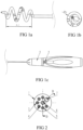
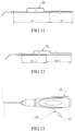
- An initial diameter of the spiral shape of the electrode support is ⁇ D, and an initial length is A-1 (referring to FIG. 1a and FIG. 1b ), and preferably, ⁇ D should be greater than a diameter of a target lumen.
- a control handle 8 is disposed at a rear end of the catheter body (referring to FIG. 1c ).
- the electrode support may be integrally manufactured with the catheter body, and the electrode support is a part of a spiral shape at the front end of the catheter body.
- the electrode support may be manufactured independently, and then is integrally connected to the catheter body.
- the electrode support of the spiral shape includes an outer tube 1 and multiple electrodes 2 disposed on the outer tube 1.
- the electrode 2 may be a block electrode or an annular electrode embedded on an outer circumference of the outer tube 1, and an upper surface of the electrode 2 may be flush with an outer surface of the outer tube 1 or is slightly higher than an outer surface of the outer tube 1, or an upper surface of the electrode 2 may be lower than an outer surface of the outer tube 1.
- a lumen used to accommodate a support wall-attachment adjusting wire 6 is disposed in the electrode support and the catheter body.
- Support wall-attachment adjusting wires 6 are disposed in corresponding lumens in the electrode support and the catheter body (referring to FIG. 2 ).
- the support wall-attachment adjusting wires 6 may slide forward and backward in the corresponding lumens in the electrode support and the catheter body, and the lumen used to accommodate the support wall-attachment adjusting wire 6 may be a central hole in the electrode support or the catheter body, or may be one of multiple lumens distributed in the periphery of the center. As shown in FIG.
- a head end of the support wall-attachment adjusting wire 6 penetrates through the electrode support, then is limited at the outside of the electrode support, and can move, relative to a far end of the electrode support, towards a direction that is far away from the catheter body.
- a developing head 63 is disposed at a head end of the support wall-attachment adjusting wire 6.
- a tail end of the support wall-attachment adjusting wire 6 penetrates through the central hole in the catheter body and is fixed on the control handle 8.
- the control handle 8 is used to control the support wall-attachment adjusting wire 6 to move forward and backward.
- a button control component 9 is disposed on the control handle 8.
- the tail end of the support wall-attachment adjusting wire 6 penetrates through the central hole in the catheter body and then is fixed on the button control component 9.
- the support wall-attachment adjusting wire 6 is controlled to move forward and backward by changing a location of the button control component 9 on the control handle 8.
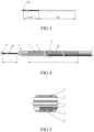
- the support wall-attachment adjusting wire 6 includes two parts: a flexible section 61 that is far away from the control handle 8 (close to the head end) and a rigid section 62 that is close to the control handle 8 (close to the tail end).
- a length of the flexible section 61 is not less than a length of the outer tube 1 of the electrode support.
- the length of the flexible section 61 may be less than the length of the outer tube 1 of the electrode support.
- the diameter of the spiral shape of the electrode support may be changed by changing, by using the control handle 8, an area in which the support wall-attachment adjusting wire 6 coincides with the electrode support.
- the support wall-attachment adjusting wire 6 moves forward to make the rigid section 62 of the support wall-attachment adjusting wire 6 be in the electrode support and the flexible section 61 of the support wall-attachment adjusting wire 6 be at the outside of electrode support, under the effect of the rigid section 62 of the support wall-attachment adjusting wire 6, the diameter of the spiral shape of the electrode support is reduced, a length is increased, and the spiral shape tends to be a straight-line shape. In an ideal case, the electrode support may present a straight-line shape shown in FIG. 4 .
- the support wall-attachment adjusting wire 6 retracts to make the flexible section 61 of the support wall-attachment adjusting wire 6 enter the electrode support, the electrode support is gradually bent with entering by the flexible section.
- the electrode support restores to the spiral shape until the rigid section 62 is not in the electrode support and only the flexible section 61 is in the electrode support (referring to FIG. 6a ).
- a diameter ⁇ C thereof is equal to or is approximate to a diameter of a target lumen (referring to FIG. 6b ).
- the length A-2 of the spiral shape of the electrode support is greater than the initial length A-1. That is, in the radio-frequency ablation catheter, the support wall-attachment adjusting wire 6 is controlled to move forward, so that the rigid section 62 of the support wall-attachment adjusting wire 6 coincides with the outer tube 1 of the electrode support, to reduce the diameter of the spiral shape of the electrode support.
- the electrode support is suitable for entering a guiding catheter/a sheath or a target lumen.
- the support wall-attachment adjusting wire 6 is pulled backward, so that the flexible section 62 of the support wall-attachment adjusting wire 6 coincides with the outer tube 1 of the electrode support, to make the electrode support restore to the spiral shape, thereby implementing wall attachment.
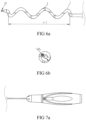
- a location of the button control component 9 on the control handle 8 may be shown in FIG. 7a and FIG. 7b .
- the button control component 9 moves to a location at the left side, the flexible section 61 is exposed, and the rigid section 62 coincides with the outer tube 1 of the electrode support.
- the button control component 9 moves to a location at the right side, the flexible section 61 of the support wall-attachment adjusting wire 6 coincides with the outer tube of the electrode support.
- a wall attachment status of the electrode 2 may be further adjusted slightly by further pulling the support wall-attachment adjusting wire 6, so that the electrode 2 is in close contact with a vessel wall, thereby improving a wall-attachment state of the electrode 2.
- the support wall-attachment adjusting wire 6 is disposed in the electrode support. After the flexible section 61 of the support wall-attachment adjusting wire 6 coincides with the outer tube of the electrode support, the support wall-attachment adjusting wire 6 is pulled again, and a range of motion of the support wall-attachment adjusting wire 6 is relatively small. Therefore, the support wall-attachment adjusting wire 6 is only used to slightly adjust the shape of the electrode support.
- a radio-frequency ablation catheter whose diameter ⁇ D of a spiral shape is greater than or is approximate to a diameter of a target lumen is recommended.
- the radio-frequency ablation catheter achieves a good wall attachment effect for a target lumen whose diameter is less than or equal to the initial diameter of the spiral shape.
- a diameter of a human renal artery vessel is within a range from 2 mm to 12 mm, to ensure that the radio-frequency ablation catheter has good adaptability to both large and small vessels, selection of a radio-frequency ablation catheter whose ⁇ D is greater than 12mm is recommended for use.
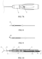
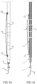
- the present invention further provides a radio-frequency ablation catheter with a support wall-attachment adjusting wire 6 having a bifurcation (referring to FIG. 10 , FIG. 11, and FIG. 12 ).
- the initial diameter ⁇ D of the spiral shape of the electrode support may be less than a diameter of a target lumen.
- the support wall-attachment adjusting wire 6 has a bifurcation that extends backward from the flexible section 61, that is, a bifurcated adjusting wire 66 in FIG. 10 , FIG. 11, and FIG. 12 .
- a head end of the bifurcated adjusting wire 66 is fixed at the head end of the support wall-attachment adjusting wire 6, or a head end of the bifurcated adjusting wire 66 is fixed at particular part of the flexible section 61, or the bifurcated adjusting wire 66 is a thin filament that is bifurcated from the flexible section 61 to the outside.
- a rear end of the bifurcated adjusting wire 66 penetrates out of a hole 11 provided on the outer tube 1 of the electrode support, penetrates into a hole 15 provided on the outer tube of the electrode support or a hole provided on the catheter body, then extends to the outside of the catheter with the support wall-attachment adjusting wire 6 side by side along a lumen in the catheter body, enters the interior of the control handle 8, and is fixed on a second control component on the control handle 8 (or an independently disposed second control component).
- the bifurcation that is, the bifurcated adjusting wire 66
- the support wall-attachment adjusting wire 6 is pulled to increase the diameter of the spiral shape of the electrode support, so that the electrode support adapts to a vessel of a relatively large diameter.
- the outer tube 1 of the electrode support may be a single-lumen tube or a multi-lumen tube, and the outer tube 1 may be made of polymer materials or metal materials, for example, materials such as stainless steel or memory alloy.
- the outer tube 1 may be processed by using straight tube materials or bar materials, or may be made into a tube of a special shape by using an A section. As shown in FIG. 2 and FIG.
- thermocouple wire 4 when the outer tube 1 uses a multi-lumen tube, in addition to the central hole, multiple lumens are further disposed in the outer tube 1 of the electrode support, one group of radio-frequency lines 3 and thermocouple wires 4 is disposed in each of some lumens, the thermocouple wire 4 is covered by a thermocouple wire head end insulation layer 5 to be separated from the radio-frequency line 3 and the electrode 2, head ends of each group of radio-frequency lines 3 and thermocouple wires 4 are disposed in a single electrode, a head end of the radio-frequency line 3 is closely soldered with the electrode 2, the head end of thermocouple wire 4 is soldered, and the head end of thermocouple wire 4 and the electrode 2 are disposed in an insulation manner.
- a spiral shaped wire 7 is further disposed in one lumen in the outer tube 1.
- the spiral shaped wire 7 is fixed on the A section in a spiral deformation area, and is used to support the spiral shape of the electrode support.
- the electrode support may be directly shaped to the spiral shape, so that the spiral shaped wire 7 can be omitted.
- the outer tube is manufactured by using memory alloy, disposition of the spiral shaped wire 7 can be omitted.
- the electrode 2 is fixed on the outer tube 1, and an outer surface of the electrode 2 may be lower than or may be not lower than the outer surface of the outer tube 1.
- the multiple electrodes 2 are evenly distributed or unevenly distributed on the spiral shape of the electrode support around a circumferential direction.
- the multiple electrodes may be distributed on the electrode support in one circle, more than one circle, or less than one circle.
- An inner surface of the electrode 2 is closely soldered with the radio-frequency line 3. Head ends of the thermocouple wires 4 are soldered together, the thermocouple wire head end insulation layer 5 is covered at a location at which the head end of the thermocouple wire 4 is soldered for insulation, and the head end of the thermocouple wire 4 is disposed in the electrode 2.
- the thermocouple wire head end insulation layer 5 may be a heat shrinkable tube or another casing.
- a first type of support wall-attachment adjusting wire 6 provided in the present invention includes two parts: a flexible section 61 that is close to a head end and a rigid section 62.
- a developing head 63 may be disposed at a head end of the support wall-attachment adjusting wire 6, and is used to develop and image a target lumen.
- Each of two types of support wall-attachment adjusting wires shown in FIG. 8 and FIG. 9 includes a flexible section 61 and a rigid section 62, and a straight-head flexible guide wire 64 or a curved-head flexible guide wire 65 is further disposed at a front end of the flexible section 61 of the support wall-attachment adjusting wire 6, so that the support wall-attachment adjusting wire 6 can directly enter a vessel by replacing a guiding catheter/a sheath, thereby simplifying operations in a surgery. Because a guiding catheter/a sheath is omitted, a diameter of the catheter that enters the vessel can be reduced greatly, which is convenient for the catheter to move.
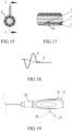
- Each of three types of support wall-attachment adjusting wires shown in FIG. 10 to FIG. 12 includes a bifurcated adjusting wire 66, and structures of the three types of bifurcated adjusting wires 66 are slightly different. Specifically, in a fourth type of support wall-attachment adjusting wire 6 shown in FIG. 10 , a head end of the bifurcated adjusting wire 66 is fixed at a head end of the support wall-attachment adjusting wire 6, and then extends backward with the flexible section 61.
- a rear end of the bifurcated adjusting wire 66 penetrates out of the hole 11 provided on the outer tube 1 of the electrode support, penetrates into a corresponding lumen from the another hole 15 provided on the electrode support or the catheter body, then extends to the outside of the catheter with the support wall-attachment adjusting wire 6 side by side along a lumen in the catheter body, and is fixed on the second control component on the control handle 8.
- the head end of the bifurcated adjusting wire 66 is fixed at a particular part of the flexible section 61, or the bifurcated adjusting wire 66 is a thin filament that is bifurcated from the flexible section 61. Then, the rear end of the bifurcated adjusting wire 66 penetrates out of the hole provided on the outer tube 1 of the electrode support, penetrates into the another hole provided on the electrode support or the catheter body, then extends to the outside of the catheter with the support wall-attachment adjusting wire 6 side by side along a lumen in the catheter body, and is fixed on the second control component on the control handle.
- a manner in which the bifurcated adjusting wire is disposed is similar to that in a structure of the fourth type of support wall-attachment adjusting wire.
- a difference is that the flexible section uses a spring structure.
- the bifurcated adjusting wire 66 is a thin filament that is bifurcated from a particular part of a spring 61-1, and the head end of the bifurcated adjusting wire 66 is fixed on the spring.
- the rear end of the bifurcated adjusting wire 66 penetrates out of the hole provided on the outer tube 1 of the electrode support, penetrates into the another hole provided on the electrode support or the catheter body, then extends to the outside of the catheter with the rigid section 62-1 of the support wall-attachment adjusting wire 6 side by side along a lumen in the catheter body, enters the control handle 8, and is fixed on the second control component on the control handle.
- the bifurcated adjusting wire 66 is pulled by using the second control component, to increase the diameter of the electrode support, so that the electrode can perform wall attachment.
- a manner in which the second control component is disposed on the control handle 8 may be the same as a manner in which the button control component 9 is disposed.
- the second control component may also be independently disposed relative to the control handle 8, as in the embodiment shown in FIG. 13 .
- the end 67 of the support wall-attachment adjusting wire 6 is fixed on the button control component 9.
- a location of the button control component 9 on the control handle 8 can be changed by pushing the button control component 9, so as to change a form of the electrode support.
- the bifurcated adjusting wire 66 extends out of an opening provided on another side surface of the control handle 8, and the second control component 10 is fixed at the end 68 of the bifurcated adjusting wire 66.
- the diameter of the spiral shape of the electrode support can be further changed by pulling the second control component 10 at the outside of the control handle 8.
- the flexible section 61 of the support wall-attachment adjusting wire 6 in FIG. 10 has a same structure as the flexible sections in the first three types of support wall-attachment adjusting wires shown in FIG. 3 , FIG. 8, and FIG. 9 , and the flexible section 61 is constructed by using a thin filament or a flexible tube.
- the flexible section 61 may be made of a thin filament whose diameter is less than that of the rigid section.
- the flexible section 61 and the rigid section 62 may be integrally molded by using a same material or may be assembled by using two thin filaments of different diameters (for example, assembled by using a soldering process).
- the flexible section 61 may also be construed by using a flexible tube.
- the flexible section 61-1 uses a spring structure.
- the electrode support can restore to the spiral shape, and the flexible section 61-1 deforms accordingly.
- the radio-frequency ablation catheter having a spiral structure that is provided in the first embodiment is described above.
- the support wall-attachment adjusting wire in the radio-frequency ablation catheter having a spiral structure is improved by referring to the structure of the guide wire, but specific functions of the two are different.
- the flexible section is used to initiatively adapt to a shape of a vessel. A direction of the guide wire is changed, so that the guide wire successfully reaches a target lumen.
- the rigid section is used to support the guide wire.
- the form of the electrode support is changed by controlling the electrode support to coincide with different areas of the support wall-attachment adjusting wire 6, so that a difficulty of entering a guiding catheter/a sheath by the radio-frequency ablation catheter can be reduced, the structure is simple, and it is easy for an operation.
- the support wall-attachment adjusting wire 6 moves forward to make the rigid section coincide with the spiral shape electrode support 2, under the effect of the rigid section of the support wall-attachment adjusting wire 6, the diameter of the spiral shape of the electrode support is reduced, the length is increased, and the spiral shape tends to be a straight-line shape, so that it is convenient for entering a guiding catheter/a sheath, and it is also convenient for the entire radio-frequency ablation catheter to move in a target lumen.
- the support wall-attachment adjusting wire 6 withdraws to make the flexible section coincide with the spiral shape electrode support, the electrode support of the spiral shape restores to the spiral shape, and wall attachment can be performed.
- the wall-attachment state of the electrode can be further improved by continuously pulling the support wall-attachment adjusting wire backward.
- the straight-head flexible guide wire or the curved-head flexible guide wire is additionally disposed at the front end of the support wall-attachment adjusting wire, and the support wall-attachment adjusting wire can further directly enter a vessel by replacing a guiding catheter/a sheath, thereby simplifying operations in a surgery.
- a support wall-attachment adjusting wire disposed in a particular lumen in the electrode support is used to adjust the diameter of the spiral shape of the electrode support.
- a wall-attachment adjusting wire that penetrates through or is wound around the electrode support may be disposed in the radio-frequency ablation catheter having a spiral structure, to adjust the increased diameter of the electrode support, so that adaptability of the electrode support to target lumens of different diameters is relatively good.
- a radio-frequency ablation catheter having a spiral structure that is provided in the present invention includes an elongated catheter body.
- An electrode support of a spiral shape is disposed at a front end of the catheter body, and a control handle 20 is disposed at a rear end of the catheter body (referring to FIG. 19 ).
- the electrode support may be integrally manufactured with the catheter body, and the electrode support is shaped to be a part of a spiral shape at the front end of the catheter body.
- the electrode support may also be manufactured independently, and then is integrally connected to the catheter body.
- the electrode support of the spiral shape includes an outer tube 1 and one or more electrodes 2 disposed on the outer tube 1.
- the electrode 2 may be a block electrode or an annular electrode embedded on an outer circumference of the outer tube, and an upper surface of the electrode 2 may be flush with an outer surface of the outer tube 1 or is slightly higher than an outer surface of the outer tube 1, or an upper surface of the electrode 2 may be lower than an outer surface of the outer tube 1.
- the multiple electrodes 2 are evenly distributed or unevenly distributed on the spiral shape of the electrode support around a circumferential direction.
- the multiple electrodes may be distributed on the electrode support in one circle, more than one circle, or less than one circle.
- the outer tube 1 of the electrode support may be a single-lumen tube or a multi-lumen tube, and the outer tube 1 may be made of polymer materials or metal materials, for example, materials such as stainless steel or memory alloy.
- the outer tube 1 may be processed by using straight tube materials or bar materials, or may be made into a tube of a special shape by using an A section. As shown in FIG. 15 and FIG.
- thermocouple wires 4 when the outer tube 1 uses a multi-lumen tube, in addition to a central lumen, multiple lumens are disposed in the outer tube 1 of the electrode support, one group of radio-frequency lines 3 and thermocouple wires 4 is disposed in each of some lumens, head ends of each group of radio-frequency lines 3 and thermocouple wires 4 are disposed in a single electrode 2, a head end of the radio-frequency line 3 is closely fixed with the electrode 2, for example, connected by using a soldering process, a conductive adhesive adhesion process, or the like, head ends of two thermocouple wires 4 are soldered, are covered by a thermocouple wire head end insulation layer 5, and then the head ends of two thermocouple wires 4 and the radio-frequency line 3 and the electrode 2 are disposed in an insulation manner.
- a spiral shaped wire 6 is further disposed in one lumen in the outer tube 1.
- the spiral shaped wire 6 is fixed on a section in a spiral deformation area, and is used to support the spiral shape of the electrode support.
- the electrode support may be directly shaped to the spiral shape, so that the spiral shaped wire 6 can be omitted.
- the outer tube is manufactured by using memory alloy or polymer materials, disposition of the spiral shaped wire 6 can be omitted.
- a support wire 7 is disposed in a central lumen in the catheter body and the electrode support, the support wire 7 may be movably disposed in the central lumen, or may be fixed in the central lumen, or the support wire 7 may be disposed in another lumen in the catheter body and the electrode support.
- a developing head may be disposed at a head end of the support wire 7, and is used to perform instant imaging on the interior of a target lumen.
- a flexible guide wire 9 may be disposed at a front end of the support wire 7.
- the flexible guide wire 9 may be a straight-head flexible guide wire or may be a curved-head flexible guide wire shown in the figure, so that the radio-frequency ablation catheter can directly enter a vessel without a guiding catheter/a sheath, thereby simplifying operations in a surgery.
- a lumen used to accommodate a wall-attachment adjusting wire 8 is further disposed the catheter body.
- a rear section of the wall-attachment adjusting wire 8 is slidably disposed in one lumen in the catheter body, and a rear end 80 of the wall-attachment adjusting wire 8 penetrates out of the catheter body and then penetrates into the control handle 20, and then penetrates out of the control handle 20 and is connected to a control component 22 on a peripheral device (referring to FIG. 19 ).
- the wall-attachment adjusting wire 8 may move forward and backward in the lumen in the catheter body.
- the lumen used to accommodate the wall-attachment adjusting wire 8 may be the central lumen, or may be one of multiple eccentric lumens distributed in the periphery of the central lumen. As shown in FIG. 14 , a front section of the wall-attachment adjusting wire 8 penetrates out of a hole 12 that is close to a rear end of the electrode support to be at the outside of the electrode support and is exposed outside the electrode support; and a front end of the he wall-attachment adjusting wire 8 returns to the interior of the electrode support from a hole 11 that is close to a front end of the electrode support and is fixed.
- a location at which the front end of the wall-attachment adjusting wire 8 is fixed may be different.
- the front end of the wall-attachment adjusting wire 8 may be fixed at the front end of the electrode support, or may be fixed at the front end of the support wire 7, or may be fixed on the spiral shaped wire 6, or may penetrate through a corresponding lumen in the electrode support and the catheter body and returns to the rear end of the catheter body, and is fixed on the control component 22 with the rear end of the wall-attachment adjusting wire 8.
- the front end of the wall-attachment adjusting wire 8 returns to the interior of the electrode support from the hole 11 that is close to the front end of the electrode support, and then returns to the rear end of the catheter body with the rear end of the wall-attachment adjusting wire 8 through a lumen in the electrode support and the catheter body. Then, the front end and the rear end of the wall-attachment adjusting wire 8 may be fixed together on a same control component 22 shown in FIG. 19 , or for the front end and the rear end of the wall-attachment adjusting wire 8, one end is fixed on a housing of the control handle 20, and the other end is fixed on the control component 22. A diameter of a spiral section of the electrode support may be changed by pulling the control component 22.
- the front end of the wall-attachment adjusting wire 8 may also be simply fixed at the front end of the electrode support, or is fixed at the front end of the support wire 7 or a particular part that is of the support wire 7 and that is located in the electrode support, or is fixed at a particular part of the spiral shaped wire 6, or is fixed in a lumen in the electrode support, as long as the front end can be fixed. Therefore, when the wall-attachment adjusting wire 8 is pulled from the rear end, under the effect of the wall-attachment adjusting wire 8, the electrode support retracts and deforms, the diameter of the spiral shape of the electrode support is increased, and an axial distance between multiple spiral shapes is reduced.
- the wall-attachment adjusting wire 8 and the support wire 7/the spiral shaped wire 6 may be manufactured by using a same material.
- the wall-attachment adjusting wire 8 is a thin filament that is bifurcated from the support wire 7/the spiral shaped wire 6 backward.
- the front end of the wall-attachment adjusting wire 8 is fixed with the front end of the spiral shaped wire 6.
- the spiral shaped wire 6 and the wall-attachment adjusting wire 8 may be manufactured by using a same thin filament, and the wall-attachment adjusting wire 8 and the spiral shaped wire 6 are respectively bifurcations of two thin filaments that are bifurcated from the front ends thereof backward.
- a bifurcation corresponding to the spiral shaped wire 6 is fixed in a particular lumen in the electrode support, and a rear section of a bifurcation corresponding to the wall-attachment adjusting wire 8 may slide in a lumen in the electrode support and/or the catheter body.
- the wall-attachment adjusting wire 8 and the spiral shaped wire 6 are manufactured by using different materials (for example, the spiral shaped wire 6 uses a tube material, and the wall-attachment adjusting wire 8 uses a thin filament), the front end/the front section of the wall-attachment adjusting wire 8 and the spiral shaped wire 6 may be assembled together through soldering, riveting, adhesion, or the like.
- a button control component 21 is further disposed on the control handle 20.
- the end 70 of the support wire 7 penetrates out of the catheter body and then enters the control handle 20, and is fixed on the button control component 21.
- the control component used to connect to the end of the support wire 7 may be further disposed at the outside of the control handle 20 as the control component 22.
- the control component used to connect to the wall-attachment adjusting wire 8 may be also disposed on the control handle 20 as the button control component 21.
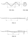
- FIG. 20A to FIG. 23B are schematic diagrams of usage states of the radio-frequency ablation catheter having a spiral structure in lumens of different diameters according to the second embodiment provided in the present invention.
- a radio-frequency ablation catheter for which an initial diameter ⁇ B of an electrode support of a spiral shape is 10 mm, an axial distance between the first and the last electrodes is A is used as an example.
- a shape of the electrode support is approximate to a straight-line shape, as shown in FIG. 21 .
- the diameter ⁇ B-3 of the spiral shape of the electrode support is limited by the diameter of the vessel to be approximately 4 mm.
- the electrode is in close contact with a vessel wall, and the axial distance (A-3) between the first and the last electrodes is greater than A (referring to FIG. 22 ). As shown in FIG. 23A and FIG.
- the radio-frequency ablation catheter extends into a vessel of ⁇ 12 mm from a sheath
- the electrode support naturally expands, because the initial diameter ⁇ B of the electrode support is less than a diameter of a target lumen, the electrode 2 cannot perform wall attachment.
- the diameter of the spiral shape of the electrode support may be increased to ⁇ B-4 by pulling the wall-attachment adjusting wire 8 backward, which is equal to the diameter of the target lumen, and under the effect of the wall-attachment adjusting wire 8, the multiple electrodes 2 are in close contact with a vessel wall.
- the axial distance between the first and the last electrodes is reduced to A-4, and the axial distance between multiple electrodes is reduced, but because the diameter of the target lumen is relatively large, mutual impact between ablation effects of the multiple electrodes may be avoided, thereby avoiding excessive ablation.
- the axial distance between the multiple electrodes 2 that are evenly distributed on the spiral shape of the electrode support is reduced, and a spiral distance is not changed.
- the electrode support whose ⁇ B is 10 mm is used as an example for description.
- the initial diameter of the spiral shape of the electrode support is another value (such as 6 mm or 8 mm)
- the multiple electrodes may be all in a good wall attachment state.
- the electrode support enters a target lumen whose diameter is greater than the initial diameter of the spiral shape, as shown in FIG. 23A and FIG. 23B , the multiple electrodes can also be all in close contact with a vessel wall by pulling the wall-attachment adjusting wire, and are in a good wall-attachment state.
- a radio-frequency ablation catheter shown in FIG. 24 has a structure similar to that of the radio-frequency ablation catheter in the second embodiment, and for a retraction state of the radio-frequency ablation catheter, refer to FIG. 25 .
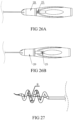
- FIG. 26A and FIG. 26B are respectively schematic diagrams of usage states of a control handle 20 of the radio-frequency ablation catheter in different states.
- a spiral shaped wire 6 is disposed in an electrode support, and a support wire 7 are disposed in a catheter body and the electrode support.
- a part that is of the support wire 7 and that corresponds to the electrode support is exposed outside the electrode support.
- a part that is of the support wire 7 and that corresponds to the catheter body is disposed in a particular lumen in the catheter body, and a rear end of the support wire 7 penetrates out of the catheter body and then is fixed on a control component 25 disposed on a control handle 20.
- the support wire 7 is pulled to change a spiral shape of the electrode support, and the support wire 7 also has a function of a wall-attachment adjusting wire 8.
- a rear section of the wall-attachment adjusting wire 8 is slidably disposed in a particular lumen in the catheter body, and a rear end of the wall-attachment adjusting wire 8 is connected to the control handle 20.
- a front section of the wall-attachment adjusting wire 8 penetrates out of the electrode support from a hole 12 and then is exposed outside the electrode support. After the front end of the wall-attachment adjusting wire 8 returns to the interior of the electrode support from a hole 11, the front end of the wall-attachment adjusting wire 8 penetrates out of a front end of the electrode support and is fixed or limited at the outside.
- the wall-attachment adjusting wire 8 is also a support wire of the catheter body.
- a developing head and/or a flexible guide wire 9 may be disposed at the front end of the wall-attachment adjusting wire 8.
- only one control component 25 connected to the support wire 7 may be disposed on the control handle 20.
- the control component 25 is used to adjust a telescopic state of the electrode support.
- the control component 25 is pushed backward from a location shown in FIG. 26A to a location shown in FIG. 26B , and the support wire 7 may be pulled backward, that is, the wall-attachment adjusting wire 8 is pulled backward, so that the diameter of the spiral shape of the electrode support is increased.
- a radio-frequency ablation catheter shown in FIG. 27 has a structure similar to that of the radio-frequency ablation catheter in the second embodiment.
- FIG. 28 shows a structure of a support wire 7 in the radio-frequency ablation catheter in the fourth embodiment.
- a structure of a wall-attachment adjusting wire 8 is the same as that in the second embodiment.
- a rear section of the wall-attachment adjusting wire 8 is slidably disposed in a particular lumen in a catheter body, and a rear end of the wall-attachment adjusting wire 8 is connected to a control component 22 disposed on a control handle 20 or penetrates out of a control handle 20 and then is connected to a control component 22 on a peripheral device.
- a front section of the wall-attachment adjusting wire 8 penetrates out of an electrode support from a hole 12 and then is exposed outside the electrode support.
- the front end of the wall-attachment adjusting wire 8 may be fixed at a front end of the electrode support or may be fixed at a front end of the support wire 7, or may penetrate through corresponding a lumen in the electrode support and the catheter body and return to a rear end of the catheter body, and is fixed on a housing of the control handle 20 or the control component 22 with the rear end of the wall-attachment adjusting wire 8.
- a diameter of a spiral section of the electrode support may be changed by pulling the control component 22.
- a spiral shaped wire is not independently disposed.
- a part that is of a front portion of the support wire 7 and that corresponds to the electrode support is shaped to a spiral shape, to form a spiral shaped section 76.
- the support wire 7 is fixed in a particular lumen in the electrode support and the catheter body, so that a corresponding part of the electrode support may have a spiral shape.
- the wall-attachment adjusting wire 8 and the support wire 7 may be both disposed in a same lumen in the catheter body, or may be independently disposed in a single lumen in the catheter body respectively.
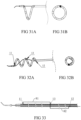
- a radio-frequency ablation catheter shown in FIG. 29 has a structure similar to that of the radio-frequency ablation catheter in the second embodiment.
- FIG. 30 shows structures of a support wire 7 and a wall-attachment adjusting wire 8 in the radio-frequency ablation catheter in the fifth embodiment, where the support wire 7, the wall-attachment adjusting wire 8, and a spiral shaped wire 6 are integrally disposed.
- the support wire 7 is disposed in a catheter body and an electrode support, and a spiral shaped wire is not independently disposed in the electrode support.
- a part that is a front portion of the support wire 7 and that corresponds to the electrode support is shaped to a spiral shape, to form a spiral shaped section 76.
- the wall-attachment adjusting wire 8 and the support wire 7 are integrally disposed.
- a front end of the wall-attachment adjusting wire 8 is fixed on the support wire 7, or the wall-attachment adjusting wire 8 is a thin filament that is bifurcated from the support wire 7 to the outside.
- a front section of the wall-attachment adjusting wire 8 penetrates out of the electrode support from a hole 11 and then is exposed outside the electrode support, and returns to the interior of the electrode support/the catheter body from a hole 12. Then, a rear section of the wall-attachment adjusting wire 8 slidably penetrates through a particular lumen in the catheter body and returns to a rear end of the catheter body, and is fixed on a control component 22. A diameter of a spiral section of the electrode support may be changed by pulling the control component 22.
- the rear section of the wall-attachment adjusting wire 8 and the support wire 7 may be both disposed in a particular lumen in the catheter body, or may be independently disposed in another lumen in the catheter body.
- FIG. 31A and FIG. 31B are schematic structural diagrams of a radio-frequency ablation catheter according to the sixth embodiment.
- the wall-attachment adjusting wire 8 is disposed in an eccentric lumen in the catheter body, a part that is of the wall-attachment adjusting wire 8 and that is exposed outside the electrode support is still located near a central location of the spiral shape of the electrode support.
- the wall-attachment adjusting wire 8 is pulled backward, the electrode support retracts axially, and the wall-attachment adjusting wire 8 penetrates through the central location of the spiral shape.
- the spiral shape of the electrode support is pulled to be approximate to a straight line, the part that is of the wall-attachment adjusting wire 8 and that is exposed outside the electrode support is almost parallel to the outer tube 1 of the electrode support.
- a wall-attachment adjusting wire 8 is not disposed near a central location of an electrode support of a spiral shape, but is disposed, in an eccentric manner, at a location on an outer circumference of the spiral shape.
- FIG. 31A and FIG. 31B when the wall-attachment adjusting wire 8 is disposed, in an eccentric manner, at a location on the outer circumference of the spiral shape of the electrode support, a part that is of the wall-attachment adjusting wire 8 and that is exposed outside the electrode support does not penetrates through the interior of the spiral shape, but is wound around an outer side of the spiral shape.
- one circle of spiral section or more than one circle of spiral section located between the holes 11 and 12 in the electrode support retracts and deforms, and a new spiral shape is obtained, so as to increase an existing diameter of the spiral shape, and increase the diameter.
- the diameter of the retracted spiral shape can be greatly increased.
- the electrode support can adapt to a vessel whose diameter is greater than a diameter of a single spiral section of the electrode support. Because a range of a diameter of a human vessel is fixed, an initial diameter of the spiral shape of the electrode support in the radio-frequency ablation catheter can be reduced, so that it is convenient for the radio-frequency ablation catheter to enter a vessel and move in the vessel.
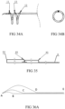
- FIG. 32A to FIG. 34B are schematic structural diagrams of a radio-frequency ablation catheter according to the seventh embodiment of the present invention.
- a front end and a rear end of the wall-attachment adjusting wire 8 both penetrate out of a rear end of a catheter body and are fixed on a control handle 20 or are externally disposed on corresponding control components outside an control handle 20.
- the part that is of the wall-attachment adjusting wire 8 and that is exposed outside the electrode support is loose.
- a particular point of the wall-attachment adjusting wire 8 that is exposed outside the electrode support is fixed on a particular spiral section of the electrode support, and the point may be directly fixed on an outer tube or may be fixed in a hole in an outer tube. To maintain a smooth outer wall of the electrode support and prevent a fixing point from scratching a target lumen, disposition of the fixing point in the hole in outer tube 1 is recommended.
- FIG. 33 there is a fixing point 13 between the wall-attachment adjusting wire 8 and a middle portion of the electrode support.
- a front section 81 of the wall-attachment adjusting wire 8 is wound forward around the outside of the electrode support from the fixing point 13, returns to the interior of the electrode support from a hole 11 that is close to a front end of the electrode support, and returns to the interior of the control handle 20 through a lumen in the electrode support and the catheter body.
- a rear section 82 of the wall-attachment adjusting wire 8 is wound backward around the outside of the electrode support from the fixing point 13, returns to the interior of the electrode support from a hole 12 that is close to a rear end of the electrode support, and returns to the interior of the control handle 20 through a lumen in the electrode support and the catheter body.
- the front section 81 and the rear section 82 of the wall-attachment adjusting wire 8 may return to the control handle 20 through a same lumen in the electrode support and the catheter body, or may respectively return to the control handle 20 through different lumens, as shown in FIG. 33 .
- One control component may be disposed on the control handle 20 and is used to fix the end of the front section 81 of the wall-attachment adjusting wire 8 and the end of the rear section 82 of the wall-attachment adjusting wire 8.
- two control components may be disposed and are used to respectively fix the end of the front section 81 of the wall-attachment adjusting wire 8 and the end of the rear section 82 of the wall-attachment adjusting wire 8, so as to respectively control the front section 81 and the rear section 82 of the wall-attachment adjusting wire 8.
- the front section 81 of the wall-attachment adjusting wire 8 is used to control to increase diameters of one or more circles of spiral sections that are of the electrode support and that are located between the hole 11 and the fixing point 13.
- the rear section 82 of the wall-attachment adjusting wire 8 is used to control to increase diameters of one or more circles of spiral sections that are of the electrode support and that are located between the hole 12 and the fixing point 13. As shown in FIG. 34A and FIG.
- the front section 81 and the rear section 82 of the wall-attachment adjusting wire may be respectively controlled by two single control components correspondingly connected to the front section 81 and the rear section 82, so as to independently adjust a diameter of a different part on the electrode support; or may be controlled together by a same control component, so as to control increase of an overall diameter of multiple spiral sections of the electrode support.
- the front section 81 and the rear section 82 of the wall-attachment adjusting wire 8 may be used to respectively control diameter increase of one or more circles of spiral sections that are of the electrode support and that are located between the hole 12 and the fixing point 13, and located between the hole 11 and the fixing point 13. Therefore, an increased diameter is equal to or even greater than the initial diameter shown in FIG. 32B , so that a better wall attachment effect can be obtained, and a target lumen whose diameter is changed within a larger range can be considered.
- a wall-attachment adjusting wire 8 disposed in a radio-frequency ablation catheter is formed by multiple strands of wires.
- a front end of each strand of wire is fixed on an electrode support; and a rear end is wound around a spiral section of the electrode support from the outside and then enters the interior of the electrode support or a catheter body, and then penetrates out of the end of the catheter body through a lumen in the catheter body and is fixed on a corresponding control component disposed on a control handle 20, or a rear end penetrates through a control handle 20 and then is fixed on a corresponding control component on a peripheral device.
- the multiple strands of wires are respectively used to independently control diameters of different spiral sections of the electrode support.
- the wall-attachment adjusting wire 8 is formed by two strands of wires 84 and 85. Front ends of the two strands of wires 84 and 85 are fixed together at a particular point on the electrode support, to form a fixing point 83. Rear ends of the two strands of wires 84 and 85 are respectively wound around different spiral sections of the electrode support, enter the interior of the electrode support or the catheter body, return to the rear end through lumens in the electrode support and the catheter body, and are fixed on corresponding control components on the control handle 20.
- a structure of the wall-attachment adjusting wire 8 having two strands of wires is basically the same as the structure in the seventh embodiment, which can be both used to respectively control diameter increase of spiral sections of a front section and a rear section of the electrode support.
- the structure in the seventh embodiment may be directly understood as a case in which the wall-attachment adjusting wire 8 in the eighth embodiment uses two strands of wires.
- a front end of each strand of wire is fixed on the electrode support, a part that is close to the front end (that is, close to the fixing point) is exposed outside the electrode support, a rear end enters the interior of the electrode support from holes provided at different locations on the electrode support, returns to the control handle 20 through a same lumen or different lumens in the electrode support and the catheter body, and is fixed on a corresponding control component.
- Fixing points of the multiple strands of wires on the electrode support may be the same, may be different, or may be not exactly the same.
- every two strands of wires may have a common fixing point on the electrode support, and for settings of structures of two strands of wires, refer to the structure shown in FIG. 35 .
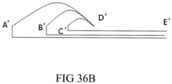
- the fixing point of the multiple strands of wires on the electrode support are the same, as shown in FIG. 36A , front ends of different wires may be fixed at the front end A of the electrode support. Then, rear ends of the strands of wires respectively enter the interior of electrode support from different holes B, C, and D and more holes on the electrode support, and penetrate out of the end of the catheter body through the electrode support and the catheter body.
- each of the multiple strands of wires is fixed on a corresponding control component.
- front ends of different wires may be fixed on a side D' at a rear portion of the electrode support.
- rear ends of the wires respectively enter the interior of the electrode support from different holes A', B', and C' and more holes that are located on at a front portion of the electrode support, and penetrate out of the end of catheter body through the electrode support and the catheter body.
- the end E' of each of the multiple strands of wires is fixed on a corresponding control component disposed on the control handle 20 or a corresponding control component on a peripheral device.
- Each strand of wire enters the interior of the electrode support from a different location on the electrode support, so that a single wire may be pulled to control a change of a diameter of a spiral section between a fixing point located at the front end and a location at which the wire enters the electrode support.
- the foregoing multiple strands of wires may also be fixed on a same control component on the control handle 20, so as to adjust an overall diameter of the electrode support.
- corresponding spiral sections of the electrode support may be expanded section by section according to a requirement, that is, only a spiral section requiring radio frequency is expanded, so as to increase flexibility of adjusting diameters of different spiral sections of the electrode support, and reduce a difficulty of adjusting wall attachment of the radio-frequency ablation catheter.
- a wall-attachment adjusting wire is disposed in a radio-frequency ablation catheter having a spiral structure, and a diameter of a spiral shape of an electrode support can be changed by pulling the wall-attachment adjusting wire backward, so as to change a wall-attachment state of an electrode, so that the radio-frequency ablation catheter adapts to vessels of different diameters.
- the wall-attachment adjusting wire may also use a multi-strand structure, so as to respectively control different spiral sections of the radio-frequency ablation catheter, and reduce a difficulty of diameter adjustment.
- the radio-frequency ablation catheter and the radio-frequency ablation device that are provided in the present invention may be applied to nerve ablation of vessels or tracheas at different parts and vessels or tracheas of multiple different diameters.
- the radio-frequency ablation catheter and the radio-frequency ablation device are applied to nerve ablation in a renal artery to treat a patient with resistant hypertension, are applied to nerve ablation in a celiac artery to treat a patient with diabetes, for another example, are applied to vagus branch ablation in a trachea/a bronchus to treat an asthmatic patient, and are applied to vagus branch ablation in dodecadactylon to treat a patient with duodenal ulcer.
- the radio-frequency ablation catheter and the radio-frequency ablation device may be further applied to nerve ablation in other vessels or tracheas such as a pelvis or a pulmonary artery.
- the radio-frequency ablation catheter provided in the present invention is not limited to the foregoing listed applications in clinic treatment, and may be further applied to nerve ablation at other parts.
- the radio-frequency ablation catheter having a spiral structure that is provided in the present invention is described above, and the present invention further provides a radio-frequency ablation device including the radio-frequency ablation catheter.
- the radio-frequency ablation device further includes a radio-frequency ablation host connected to the radio-frequency ablation catheter.
- a support wall-attachment adjusting wire (and a bifurcated adjusting wire thereof) or a wall-attachment adjusting wire in an electrode support penetrates through a catheter body and then is connected to a corresponding control handle.
- a shape of the electrode support can be changed by pulling the support wall-attachment adjusting wire by the control handle, so that it is convenient for entering a target lumen, and a wall attachment state in the target lumen is good.
- the shape of the electrode support can be changed by pulling wall-attachment adjusting wire by the control handle, so that wall-attachment states of the electrode support in target lumens of different diameters are good.
- a radio-frequency line and a thermocouple wire in the electrode support are respectively connected to corresponding circuits in the radio-frequency ablation host through the catheter body, so that the radio-frequency ablation host implements radio frequency control and temperature monitoring on multiple electrodes.
- radio-frequency ablation catheter having a spiral structure and the device thereof that are provided in the present invention are described in detail above.
- any obvious modification made to the present invention without departing from the scope of appended claims shall fall within the protection scope of the present invention.
Landscapes
- Health & Medical Sciences (AREA)
- Surgery (AREA)
- Life Sciences & Earth Sciences (AREA)
- Engineering & Computer Science (AREA)
- Heart & Thoracic Surgery (AREA)
- Medical Informatics (AREA)
- Otolaryngology (AREA)
- Plasma & Fusion (AREA)
- Physics & Mathematics (AREA)
- Biomedical Technology (AREA)
- Veterinary Medicine (AREA)
- Nuclear Medicine, Radiotherapy & Molecular Imaging (AREA)
- Molecular Biology (AREA)
- Animal Behavior & Ethology (AREA)
- General Health & Medical Sciences (AREA)
- Public Health (AREA)
- Cardiology (AREA)
- Surgical Instruments (AREA)
- Media Introduction/Drainage Providing Device (AREA)
- Measurement And Recording Of Electrical Phenomena And Electrical Characteristics Of The Living Body (AREA)
Claims (12)
- Funkfrequenzablationskatheter mit Spiralstruktur, umfassend einen länglichen Katheterkörper, worin ein Elektrodenträger einer Spiralform an einem vorderen Ende des Katheterkörpers angeordnet ist, mehrere Elektroden (2) auf dem Elektrodenträger angeordnet sind, und ein Steuerhandgriff (8) an einem hinteren Ende des Katheterkörpers angeordnet ist, worinein verschiebbarer Stützwandbefestigungs-Einstellungsdraht (6) in einem Lumen im Elektrodenträger und im Katheterkörper angeordnet ist, und der Stützwandbefestigungs-Einstellungsdraht (6) aus einem flexiblen Querschnitt (61), der vom Steuerhandgriff (8) fern liegt, und aus einem starren Querschnitt (62), der dem Steuerhandgriff (8) nahe liegt, besteht;ein Schwanzende des Stützwandbefestigungs-Einstellungsdrahts (6) durch den Katheterkörper durchdringt und am Steuerhandgriff (8) befestigt ist; und der Steuerhandgriff (8) verwendet wird, um den Stützwandbefestigungs-Einstellungsdraht (6) zu steuern, damit er sich vorwärts und rückwärts bewegt;wenn der Stützwandbefestigungs-Einstellungsdraht (6) vorwärts bewegt wird, um zu veranlassen, dass der starre Querschnitt (62) sich innerhalb des Elektrodenträgers befindet und der flexible Querschnitt (61) sich außerhalb des Elektrodenträgers befindet, unter der Einwirkung des starren Querschnitts (62) des Stützwandbefestigungs-Einstellungsdrahts (6), ein Durchmesser der Spiralform des Elektrodenträgers reduziert wird, eine Länge erhöht wird und die Spiralform dazu neigt, eine geradlinige Form zu sein; undwenn der Stützwandbefestigungs-Einstellungsdraht (6) zurückgezogen wird, um zu veranlassen, dass der flexible Querschnitt (61) sich innerhalb des Elektrodenträgers befindet, der Elektrodenträger zur Spiralform zurückgeführt wird.
- Funkfrequenzablationskatheter mit Spiralstruktur nach Anspruch 1, worin
ein Kopfende des Stützwandbefestigungs-Einstellungsdrahts (6) durch den Elektrodenträger durchdringt, dann auf das Äußere des Elektrodenträgers begrenzt ist, und sich zu einer Richtung hin bewegen kann, die vom Katheter und vom Elektrodenträger weit ist. - Funkfrequenzablationskatheter mit Spiralstruktur nach Anspruch 1, worin
ein Knopfsteuerbauteil (9), das mit dem Schwanzende des Stützwandbefestigungs-Einstellungsdrahts (6) fixiert ist, am Steuerhandgriff (8) angeordnet ist, und der Stützwandbefestigungs-Einstellungsdraht (6) gesteuert wird, um sich zu bewegen, indem eine Stellung des Knopfsteuerbauteils (9) am Steuerhandgriff (8) geändert wird. - Funkfrequenzablationskatheter mit Spiralstruktur nach Anspruch 1, worin
ein Entwicklungskopf (63) am Kopfende des Stützwandbefestigungs-Einstellungsdrahts (6) angeordnet ist. - Funkfrequenzablationskatheter mit Spiralstruktur nach Anspruch 1, worin
der Stützwandbefestigungs-Einstellungsdraht (6) einen gegabelten Einstellungsdraht (66) aufweist, der sich nach hinten erstreckt; ein Kopfende des gegabelten Einstellungsdrahts (66) am Kopfende des Stützwandbefestigungs-Einstellungsdrahts (6) fixiert ist, oder ein Kopfende des gegabelten Einstellungsdrahts (66) an einem besonderen Teil des flexiblen Querschnitts (61) fixiert ist, oder der gegabelte Einstellungsdraht (66) ein dünner Faden ist, der vom flexiblen Querschnitt (61) zum Äußeren hin gegabelt ist; und ein hinteres Ende des gegabelten Einstellungsdrahts (6) aus einem Loch (11) heraus durchdringt, das an einem äußeren Rohr (1) am Elektrodenträger vorgesehen ist, in ein Loch (15) eindringt, das am Elektrodenträger oder am Katheterkörper vorgesehen ist, sich dann zum Äußeren des Katheters mit dem starren Querschnitt (62) des Stützwandbefestigungs-Einstellungsdrahts (6) hin Seite an Seite entlang eines Lumens im Katheterkörper erstreckt, in das Innere des Steuerhandgriffs (8) eintritt, und an einem zweiten Steuerbauteil (10) fixiert ist. - Funkfrequenzablationskatheter mit Spiralstruktur nach Anspruch 1, worin
eine Länge des flexiblen Querschnitts (61) nicht kleiner ist als eine Länge des äußeren Rohres (1) des Elektrodenträgers. - Funkfrequenzablationskatheter mit Spiralstruktur nach Anspruch 1, worin
ein geradköpfiger flexibler Führungsdraht (64) oder ein krummköpfiger flexibler Führungsdraht (65) an einem vorderen Ende des flexiblen Querschnitts (61) angeordnet ist. - Funkfrequenzablationskatheter mit Spiralstruktur nach Anspruch 1, worin
der flexible Querschnitt (61) aus einem dünnen Faden hergestellt ist, dessen Durchmesser kleiner ist als derjenige des starren Querschnitts (62); und der flexible Querschnitt (61) und der starre Querschnitt (62) einstückig geformt sind oder durch Verwendung von zwei dünnen Fäden mit verschiedenen Durchmessern zusammengesetzt sind. - Funkfrequenzablationskatheter mit Spiralstruktur nach Anspruch 1, worin
der flexible Querschnitt (62) eine Federstruktur (61-1) oder eine flexible Rohrstruktur benutzt. - Funkfrequenzablationskatheter mit Spiralstruktur nach Anspruch 1, worin
der Elektrodenträger ein äußeres Rohr (1) umfasst, mehrere Elektroden (2) an einem äußeren Umfang des äußeren Rohres (1) eingebettet sind, mehrere Lumina im äußeren Rohr (1) eingebettet sind, eine Gruppe von Thermoelementdrähten (4) und Funkfrequenzleitungen (3) in jedem von einigen Lumina angeordnet ist, eine Gruppe von Funkfrequenzleitungen (3) und Thermoelementdrähten (4) in jeder Elektrode (2) angeordnet ist, die Funkfrequenzleitung (3) mit der Elektrode (2) verbunden ist, und der Thermoelementdraht (4) und die Elektrode (2) in einer isolierten Weise angeordnet sind. - Funkfrequenzablationskatheter mit Spiralstruktur nach Anspruch 1, worin
ein spiralförmiger Draht (7) im Elektrodenträger angeordnet ist. - Funkfrequenzablationsvorrichtung, umfassend den Funkfrequenzablationskatheter nach einem der Ansprüche 1 bis 11 und einen Funkfrequenzablationshost, der mit dem Funkfrequenzablationskatheter verbunden ist.
Priority Applications (1)
| Application Number | Priority Date | Filing Date | Title |
|---|---|---|---|
| EP18162451.1A EP3360497B1 (de) | 2015-02-03 | 2016-02-03 | Hochfrequenzablationskatheter mit spiralstruktur und vorrichtung dafür |
Applications Claiming Priority (7)
| Application Number | Priority Date | Filing Date | Title |
|---|---|---|---|
| CN201510057095.5A CN104605930A (zh) | 2014-12-29 | 2015-02-03 | 一种螺旋结构的射频消融导管及其设备 |
| CN201510129947.7A CN104688334A (zh) | 2015-03-23 | 2015-03-23 | 具有贴壁调节丝的螺旋型射频消融导管及其设备 |
| CN201520433569.7U CN204734547U (zh) | 2015-03-23 | 2015-06-19 | 具有贴壁调节丝的螺旋型射频消融导管及其设备 |
| CN201520434410.7U CN204971568U (zh) | 2015-06-19 | 2015-06-19 | 一种螺旋结构的射频消融导管及其设备 |
| CN201510350172.6A CN104939918B (zh) | 2015-03-23 | 2015-06-19 | 具有贴壁调节丝的螺旋型射频消融导管及其设备 |
| CN201510349237.5A CN105193497B (zh) | 2014-12-29 | 2015-06-19 | 一种螺旋结构的射频消融导管及其设备 |
| PCT/CN2016/073378 WO2016124138A1 (zh) | 2015-02-03 | 2016-02-03 | 一种螺旋结构的射频消融导管及其设备 |
Related Child Applications (2)
| Application Number | Title | Priority Date | Filing Date |
|---|---|---|---|
| EP18162451.1A Division-Into EP3360497B1 (de) | 2015-02-03 | 2016-02-03 | Hochfrequenzablationskatheter mit spiralstruktur und vorrichtung dafür |
| EP18162451.1A Division EP3360497B1 (de) | 2015-02-03 | 2016-02-03 | Hochfrequenzablationskatheter mit spiralstruktur und vorrichtung dafür |
Publications (4)
| Publication Number | Publication Date |
|---|---|
| EP3254635A1 EP3254635A1 (de) | 2017-12-13 |
| EP3254635A4 EP3254635A4 (de) | 2018-07-25 |
| EP3254635C0 EP3254635C0 (de) | 2023-08-30 |
| EP3254635B1 true EP3254635B1 (de) | 2023-08-30 |
Family
ID=56563470
Family Applications (2)
| Application Number | Title | Priority Date | Filing Date |
|---|---|---|---|
| EP18162451.1A Active EP3360497B1 (de) | 2015-02-03 | 2016-02-03 | Hochfrequenzablationskatheter mit spiralstruktur und vorrichtung dafür |
| EP16746133.4A Active EP3254635B1 (de) | 2015-02-03 | 2016-02-03 | Hochfrequenzablationskatheter mit spiralstruktur und ausrüstung dafür |
Family Applications Before (1)
| Application Number | Title | Priority Date | Filing Date |
|---|---|---|---|
| EP18162451.1A Active EP3360497B1 (de) | 2015-02-03 | 2016-02-03 | Hochfrequenzablationskatheter mit spiralstruktur und vorrichtung dafür |
Country Status (5)
| Country | Link |
|---|---|
| US (1) | US10646272B2 (de) |
| EP (2) | EP3360497B1 (de) |
| JP (2) | JP6716607B2 (de) |
| ES (2) | ES2979139T3 (de) |
| WO (1) | WO2016124138A1 (de) |
Families Citing this family (16)
| Publication number | Priority date | Publication date | Assignee | Title |
|---|---|---|---|---|
| CA2856732A1 (en) | 2011-12-09 | 2013-06-13 | Metavention, Inc. | Therapeutic neuromodulation of the hepatic system |
| US20150111918A1 (en) | 2012-03-08 | 2015-04-23 | Medtronic Ardian Luxembourg S.a.r.l | Immune system neuromodulation and associated systems and methods |
| CA2913346A1 (en) | 2013-06-05 | 2014-12-11 | Metavention, Inc. | Modulation of targeted nerve fibers |
| EP3226795B1 (de) | 2014-12-03 | 2020-08-26 | Metavention, Inc. | Systeme zur modulation von nerven oder anderem gewebe |
| WO2016124138A1 (zh) * | 2015-02-03 | 2016-08-11 | 上海魅丽纬叶医疗科技有限公司 | 一种螺旋结构的射频消融导管及其设备 |
| US10524859B2 (en) | 2016-06-07 | 2020-01-07 | Metavention, Inc. | Therapeutic tissue modulation devices and methods |
| US12575878B2 (en) | 2019-05-07 | 2026-03-17 | CRC EP, Inc. | Mapping and ablation catheter with multiple loop segments |
| CN111012477B (zh) * | 2019-12-25 | 2025-01-24 | 美安创新医疗科技无锡有限公司 | 一种具有机械支撑系统的射频消融导管 |
| US11712295B2 (en) | 2019-12-30 | 2023-08-01 | Biosense Webster (Israel) Ltd. | Multi-purpose sensing and radiofrequency (RF) ablation spiral electrode for catheter |
| CN115363689A (zh) * | 2021-05-21 | 2022-11-22 | 上海微创心通医疗科技有限公司 | 一种医用导管及医用装置 |
| CN113384319B (zh) * | 2021-06-02 | 2023-04-25 | 上海腾复医疗科技有限公司 | 一种导管 |
| CN113633373B (zh) * | 2021-08-02 | 2024-12-06 | 上海安通医疗科技有限公司 | 一种经桡动脉穿刺消融导管 |
| CN114271929B (zh) * | 2021-12-26 | 2023-04-07 | 上海安通医疗科技有限公司 | 一种适用于桡动脉的自控制消融导管 |
| CN114271928B (zh) * | 2021-12-26 | 2023-07-28 | 上海安通医疗科技有限公司 | 一种可用于桡动脉的组合式消融导管 |
| CN114767256A (zh) * | 2022-01-27 | 2022-07-22 | 苏州心岭迈德医疗科技有限公司 | 一种电极间距变化的消融导管及设备 |
| CN117547347B (zh) * | 2024-01-11 | 2024-07-05 | 乐普(北京)医疗器械股份有限公司 | 一种射频消融装置 |
Family Cites Families (25)
| Publication number | Priority date | Publication date | Assignee | Title |
|---|---|---|---|---|
| US5921924A (en) * | 1993-12-03 | 1999-07-13 | Avitall; Boaz | Mapping and ablation catheter system utilizing multiple control elements |
| US5702438A (en) * | 1995-06-08 | 1997-12-30 | Avitall; Boaz | Expandable recording and ablation catheter system |
| US6332880B1 (en) * | 1996-12-19 | 2001-12-25 | Ep Technologies, Inc. | Loop structures for supporting multiple electrode elements |
| EP1108441A3 (de) * | 1997-10-30 | 2001-07-04 | E.P. Technologies, Inc. | Distale einheit mit Zugdrähten für einen Katheter |
| US6613046B1 (en) * | 1999-11-22 | 2003-09-02 | Scimed Life Systems, Inc. | Loop structures for supporting diagnostic and therapeutic elements in contact with body tissue |
| JP4558251B2 (ja) * | 1999-11-22 | 2010-10-06 | ボストン サイエンティフィック リミテッド | 身体組織と接触させて診断要素および治療要素を支持するためのループ構造体 |
| CN101309651B (zh) * | 2005-06-20 | 2011-12-07 | 麦德托尼克消融前沿有限公司 | 消融导管 |
| US20090264770A1 (en) * | 2008-04-17 | 2009-10-22 | Omnisonics Medical Technologies, Inc. | Medical Systems and Related Methods |
| CN201469401U (zh) | 2009-08-21 | 2010-05-19 | 刘小青 | 螺旋状环肾动脉肾交感神经射频消融电极导管 |
| US9387035B2 (en) * | 2009-08-25 | 2016-07-12 | Medtronic Ablation Frontiers Llc | Bi-modal catheter steering mechanism |
| JP2013544133A (ja) * | 2010-10-25 | 2013-12-12 | メドトロニック アーディアン ルクセンブルク ソシエテ ア レスポンサビリテ リミテ | 腎ニューロモジュレーションのためのマルチ電極アレイを有するカテーテル装置ならびに関連のシステムおよび方法 |
| US9220433B2 (en) * | 2011-06-30 | 2015-12-29 | Biosense Webster (Israel), Ltd. | Catheter with variable arcuate distal section |
| CN102488552B (zh) * | 2011-12-15 | 2015-04-15 | 四川锦江电子科技有限公司 | 可操控螺旋形电生理导管 |
| US9717555B2 (en) * | 2012-05-14 | 2017-08-01 | Biosense Webster (Israel), Ltd. | Catheter with helical end section for vessel ablation |
| CN103830001B (zh) * | 2012-11-23 | 2016-12-21 | 四川锦江电子科技有限公司 | 可控弯螺旋消融导管 |
| US20160256216A1 (en) * | 2013-03-11 | 2016-09-08 | Medtronic Ardian Luxembourg S.A.R.L. | Catheter apparatuses for pulmonary artery neuromodulation |
| US9848948B2 (en) * | 2013-03-15 | 2017-12-26 | Biosense Webster (Israel) Ltd. | Catheter adapted for use with guide wire for accessing vessels |
| US9179974B2 (en) * | 2013-03-15 | 2015-11-10 | Medtronic Ardian Luxembourg S.A.R.L. | Helical push wire electrode |
| CN104095679A (zh) * | 2013-04-12 | 2014-10-15 | 上海微创电生理医疗科技有限公司 | 多电极消融导管 |
| CN203280485U (zh) | 2013-04-12 | 2013-11-13 | 上海微创电生理医疗科技有限公司 | 多电极消融导管 |
| EP2986229A4 (de) * | 2013-04-16 | 2016-09-28 | Transmed7 Llc | Verfahren, vorrichtungen und therapeutische plattform für automatisierte und auswählbare weichgeweberesektion |
| CN104605930A (zh) * | 2014-12-29 | 2015-05-13 | 上海魅丽纬叶医疗科技有限公司 | 一种螺旋结构的射频消融导管及其设备 |
| WO2016124138A1 (zh) * | 2015-02-03 | 2016-08-11 | 上海魅丽纬叶医疗科技有限公司 | 一种螺旋结构的射频消融导管及其设备 |
| CN204971568U (zh) * | 2015-06-19 | 2016-01-20 | 上海魅丽纬叶医疗科技有限公司 | 一种螺旋结构的射频消融导管及其设备 |
| CN104688334A (zh) * | 2015-03-23 | 2015-06-10 | 上海魅丽纬叶医疗科技有限公司 | 具有贴壁调节丝的螺旋型射频消融导管及其设备 |
-
2016
- 2016-02-03 WO PCT/CN2016/073378 patent/WO2016124138A1/zh not_active Ceased
- 2016-02-03 ES ES18162451T patent/ES2979139T3/es active Active
- 2016-02-03 US US15/548,672 patent/US10646272B2/en active Active
- 2016-02-03 ES ES16746133T patent/ES2955930T3/es active Active
- 2016-02-03 JP JP2017558612A patent/JP6716607B2/ja active Active
- 2016-02-03 EP EP18162451.1A patent/EP3360497B1/de active Active
- 2016-02-03 EP EP16746133.4A patent/EP3254635B1/de active Active
-
2020
- 2020-04-14 JP JP2020072220A patent/JP6987920B2/ja active Active
Also Published As
| Publication number | Publication date |
|---|---|
| ES2955930T3 (es) | 2023-12-11 |
| US20170354462A1 (en) | 2017-12-14 |
| EP3254635A4 (de) | 2018-07-25 |
| EP3360497A1 (de) | 2018-08-15 |
| JP2020116423A (ja) | 2020-08-06 |
| EP3254635A1 (de) | 2017-12-13 |
| ES2979139T3 (es) | 2024-09-24 |
| EP3254635C0 (de) | 2023-08-30 |
| EP3360497C0 (de) | 2024-05-22 |
| JP2018503490A (ja) | 2018-02-08 |
| JP6987920B2 (ja) | 2022-01-05 |
| WO2016124138A1 (zh) | 2016-08-11 |
| US10646272B2 (en) | 2020-05-12 |
| JP6716607B2 (ja) | 2020-07-01 |
| EP3360497B1 (de) | 2024-05-22 |
Similar Documents
| Publication | Publication Date | Title |
|---|---|---|
| EP3254635B1 (de) | Hochfrequenzablationskatheter mit spiralstruktur und ausrüstung dafür | |
| CN107569283B (zh) | 具有贴壁调节丝的螺旋型射频消融导管及其设备 | |
| CN205913392U (zh) | 具有瓣状支架结构的射频消融导管及其设备 | |
| US11090464B2 (en) | Rotationally torquable endovascular device with actuatable working end | |
| EP2656870B1 (de) | Führungsdraht | |
| CN105193497B (zh) | 一种螺旋结构的射频消融导管及其设备 | |
| WO2016019761A1 (zh) | 具有网管状支架结构的射频消融导管及其设备 | |
| EP3295885B1 (de) | Gewellter hochfrequenz-ablationskatheter mit wandfixierungsanpassungsdrähten und vorrichtung dafür | |
| CN107072714A (zh) | 用于将射频和/或微波频率能量输送到电外科器械的电缆 | |
| EP3030133A1 (de) | Gekrümmte spitze aus einem durchgehenden verbundstoff zur kanülierung | |
| CN113749834B (zh) | 一种支架递送系统 | |
| EP3295883B1 (de) | Gewellter radiofrequenzablationskatheter und vorrichtung dafür | |
| US10898682B2 (en) | Microtube guide | |
| CN204971568U (zh) | 一种螺旋结构的射频消融导管及其设备 | |
| CN105125281B (zh) | 一种波纹型射频消融导管及其设备 | |
| CN205019160U (zh) | 一种波纹型射频消融导管及其设备 | |
| CN114271928A (zh) | 一种可用于桡动脉的组合式消融导管 | |
| WO2017205355A1 (en) | Microtube guide |
Legal Events
| Date | Code | Title | Description |
|---|---|---|---|
| STAA | Information on the status of an ep patent application or granted ep patent |
Free format text: STATUS: THE INTERNATIONAL PUBLICATION HAS BEEN MADE |
|
| PUAI | Public reference made under article 153(3) epc to a published international application that has entered the european phase |
Free format text: ORIGINAL CODE: 0009012 |
|
| STAA | Information on the status of an ep patent application or granted ep patent |
Free format text: STATUS: REQUEST FOR EXAMINATION WAS MADE |
|
| 17P | Request for examination filed |
Effective date: 20170830 |
|
| AK | Designated contracting states |
Kind code of ref document: A1 Designated state(s): AL AT BE BG CH CY CZ DE DK EE ES FI FR GB GR HR HU IE IS IT LI LT LU LV MC MK MT NL NO PL PT RO RS SE SI SK SM TR |
|
| AX | Request for extension of the european patent |
Extension state: BA ME |
|
| DAV | Request for validation of the european patent (deleted) | ||
| DAX | Request for extension of the european patent (deleted) | ||
| A4 | Supplementary search report drawn up and despatched |
Effective date: 20180621 |
|
| RIC1 | Information provided on ipc code assigned before grant |
Ipc: A61B 18/00 20060101ALI20180615BHEP Ipc: A61B 17/00 20060101ALI20180615BHEP Ipc: A61B 18/14 20060101ALI20180615BHEP Ipc: A61B 18/12 20060101AFI20180615BHEP |
|
| STAA | Information on the status of an ep patent application or granted ep patent |
Free format text: STATUS: EXAMINATION IS IN PROGRESS |
|
| 17Q | First examination report despatched |
Effective date: 20221025 |
|
| GRAP | Despatch of communication of intention to grant a patent |
Free format text: ORIGINAL CODE: EPIDOSNIGR1 |
|
| STAA | Information on the status of an ep patent application or granted ep patent |
Free format text: STATUS: GRANT OF PATENT IS INTENDED |
|
| INTG | Intention to grant announced |
Effective date: 20230320 |
|
| GRAS | Grant fee paid |
Free format text: ORIGINAL CODE: EPIDOSNIGR3 |
|
| GRAA | (expected) grant |
Free format text: ORIGINAL CODE: 0009210 |
|
| STAA | Information on the status of an ep patent application or granted ep patent |
Free format text: STATUS: THE PATENT HAS BEEN GRANTED |
|
| AK | Designated contracting states |
Kind code of ref document: B1 Designated state(s): AL AT BE BG CH CY CZ DE DK EE ES FI FR GB GR HR HU IE IS IT LI LT LU LV MC MK MT NL NO PL PT RO RS SE SI SK SM TR |
|
| REG | Reference to a national code |
Ref country code: GB Ref legal event code: FG4D |
|
| REG | Reference to a national code |
Ref country code: CH Ref legal event code: EP |
|
| REG | Reference to a national code |
Ref country code: DE Ref legal event code: R096 Ref document number: 602016082310 Country of ref document: DE |
|
| REG | Reference to a national code |
Ref country code: IE Ref legal event code: FG4D |
|
| U01 | Request for unitary effect filed |
Effective date: 20230926 |
|
| U07 | Unitary effect registered |
Designated state(s): AT BE BG DE DK EE FI FR IT LT LU LV MT NL PT SE SI Effective date: 20231002 |
|
| REG | Reference to a national code |
Ref country code: ES Ref legal event code: FG2A Ref document number: 2955930 Country of ref document: ES Kind code of ref document: T3 Effective date: 20231211 |
|
| PG25 | Lapsed in a contracting state [announced via postgrant information from national office to epo] |
Ref country code: GR Free format text: LAPSE BECAUSE OF FAILURE TO SUBMIT A TRANSLATION OF THE DESCRIPTION OR TO PAY THE FEE WITHIN THE PRESCRIBED TIME-LIMIT Effective date: 20231201 |
|
| PG25 | Lapsed in a contracting state [announced via postgrant information from national office to epo] |
Ref country code: IS Free format text: LAPSE BECAUSE OF FAILURE TO SUBMIT A TRANSLATION OF THE DESCRIPTION OR TO PAY THE FEE WITHIN THE PRESCRIBED TIME-LIMIT Effective date: 20231230 |
|
| PG25 | Lapsed in a contracting state [announced via postgrant information from national office to epo] |
Ref country code: RS Free format text: LAPSE BECAUSE OF FAILURE TO SUBMIT A TRANSLATION OF THE DESCRIPTION OR TO PAY THE FEE WITHIN THE PRESCRIBED TIME-LIMIT Effective date: 20230830 Ref country code: NO Free format text: LAPSE BECAUSE OF FAILURE TO SUBMIT A TRANSLATION OF THE DESCRIPTION OR TO PAY THE FEE WITHIN THE PRESCRIBED TIME-LIMIT Effective date: 20231130 Ref country code: IS Free format text: LAPSE BECAUSE OF FAILURE TO SUBMIT A TRANSLATION OF THE DESCRIPTION OR TO PAY THE FEE WITHIN THE PRESCRIBED TIME-LIMIT Effective date: 20231230 Ref country code: HR Free format text: LAPSE BECAUSE OF FAILURE TO SUBMIT A TRANSLATION OF THE DESCRIPTION OR TO PAY THE FEE WITHIN THE PRESCRIBED TIME-LIMIT Effective date: 20230830 Ref country code: GR Free format text: LAPSE BECAUSE OF FAILURE TO SUBMIT A TRANSLATION OF THE DESCRIPTION OR TO PAY THE FEE WITHIN THE PRESCRIBED TIME-LIMIT Effective date: 20231201 |
|
| PG25 | Lapsed in a contracting state [announced via postgrant information from national office to epo] |
Ref country code: PL Free format text: LAPSE BECAUSE OF FAILURE TO SUBMIT A TRANSLATION OF THE DESCRIPTION OR TO PAY THE FEE WITHIN THE PRESCRIBED TIME-LIMIT Effective date: 20230830 |
|
| U20 | Renewal fee for the european patent with unitary effect paid |
Year of fee payment: 9 Effective date: 20240227 |
|
| PG25 | Lapsed in a contracting state [announced via postgrant information from national office to epo] |
Ref country code: SM Free format text: LAPSE BECAUSE OF FAILURE TO SUBMIT A TRANSLATION OF THE DESCRIPTION OR TO PAY THE FEE WITHIN THE PRESCRIBED TIME-LIMIT Effective date: 20230830 Ref country code: RO Free format text: LAPSE BECAUSE OF FAILURE TO SUBMIT A TRANSLATION OF THE DESCRIPTION OR TO PAY THE FEE WITHIN THE PRESCRIBED TIME-LIMIT Effective date: 20230830 Ref country code: CZ Free format text: LAPSE BECAUSE OF FAILURE TO SUBMIT A TRANSLATION OF THE DESCRIPTION OR TO PAY THE FEE WITHIN THE PRESCRIBED TIME-LIMIT Effective date: 20230830 Ref country code: SK Free format text: LAPSE BECAUSE OF FAILURE TO SUBMIT A TRANSLATION OF THE DESCRIPTION OR TO PAY THE FEE WITHIN THE PRESCRIBED TIME-LIMIT Effective date: 20230830 |
|
| REG | Reference to a national code |
Ref country code: DE Ref legal event code: R097 Ref document number: 602016082310 Country of ref document: DE |
|
| PLBE | No opposition filed within time limit |
Free format text: ORIGINAL CODE: 0009261 |
|
| STAA | Information on the status of an ep patent application or granted ep patent |
Free format text: STATUS: NO OPPOSITION FILED WITHIN TIME LIMIT |
|
| 26N | No opposition filed |
Effective date: 20240603 |
|
| PG25 | Lapsed in a contracting state [announced via postgrant information from national office to epo] |
Ref country code: MC Free format text: LAPSE BECAUSE OF FAILURE TO SUBMIT A TRANSLATION OF THE DESCRIPTION OR TO PAY THE FEE WITHIN THE PRESCRIBED TIME-LIMIT Effective date: 20230830 |
|
| U20 | Renewal fee for the european patent with unitary effect paid |
Year of fee payment: 10 Effective date: 20250221 |
|
| PG25 | Lapsed in a contracting state [announced via postgrant information from national office to epo] |
Ref country code: CY Free format text: LAPSE BECAUSE OF FAILURE TO SUBMIT A TRANSLATION OF THE DESCRIPTION OR TO PAY THE FEE WITHIN THE PRESCRIBED TIME-LIMIT; INVALID AB INITIO Effective date: 20160203 |
|
| PG25 | Lapsed in a contracting state [announced via postgrant information from national office to epo] |
Ref country code: HU Free format text: LAPSE BECAUSE OF FAILURE TO SUBMIT A TRANSLATION OF THE DESCRIPTION OR TO PAY THE FEE WITHIN THE PRESCRIBED TIME-LIMIT; INVALID AB INITIO Effective date: 20160203 |
|
| PG25 | Lapsed in a contracting state [announced via postgrant information from national office to epo] |
Ref country code: TR Free format text: LAPSE BECAUSE OF FAILURE TO SUBMIT A TRANSLATION OF THE DESCRIPTION OR TO PAY THE FEE WITHIN THE PRESCRIBED TIME-LIMIT Effective date: 20230830 |
|
| U20 | Renewal fee for the european patent with unitary effect paid |
Year of fee payment: 11 Effective date: 20251203 |
|
| PGFP | Annual fee paid to national office [announced via postgrant information from national office to epo] |
Ref country code: GB Payment date: 20251203 Year of fee payment: 11 |
|
| PGFP | Annual fee paid to national office [announced via postgrant information from national office to epo] |
Ref country code: IE Payment date: 20251203 Year of fee payment: 11 |
|
| REG | Reference to a national code |
Ref country code: CH Ref legal event code: U11 Free format text: ST27 STATUS EVENT CODE: U-0-0-U10-U11 (AS PROVIDED BY THE NATIONAL OFFICE) Effective date: 20260301 |
|
| PGFP | Annual fee paid to national office [announced via postgrant information from national office to epo] |
Ref country code: ES Payment date: 20260327 Year of fee payment: 11 |
|
| PGFP | Annual fee paid to national office [announced via postgrant information from national office to epo] |
Ref country code: CH Payment date: 20260301 Year of fee payment: 11 |