EP3252804B1 - Einheit zur elektrostatischen entladung - Google Patents
Einheit zur elektrostatischen entladung Download PDFInfo
- Publication number
- EP3252804B1 EP3252804B1 EP16172947.0A EP16172947A EP3252804B1 EP 3252804 B1 EP3252804 B1 EP 3252804B1 EP 16172947 A EP16172947 A EP 16172947A EP 3252804 B1 EP3252804 B1 EP 3252804B1
- Authority
- EP
- European Patent Office
- Prior art keywords
- electrostatic discharge
- discharge unit
- transport
- transport roller
- rolling
- Prior art date
- Legal status (The legal status is an assumption and is not a legal conclusion. Google has not performed a legal analysis and makes no representation as to the accuracy of the status listed.)
- Active
Links
Images




Classifications
-
- H—ELECTRICITY
- H10—SEMICONDUCTOR DEVICES; ELECTRIC SOLID-STATE DEVICES NOT OTHERWISE PROVIDED FOR
- H10P—GENERIC PROCESSES OR APPARATUS FOR THE MANUFACTURE OR TREATMENT OF DEVICES COVERED BY CLASS H10
- H10P72/00—Handling or holding of wafers, substrates or devices during manufacture or treatment thereof
- H10P72/30—Handling or holding of wafers, substrates or devices during manufacture or treatment thereof for conveying, e.g. between different workstations
- H10P72/32—Handling or holding of wafers, substrates or devices during manufacture or treatment thereof for conveying, e.g. between different workstations between different workstations
- H10P72/3202—Mechanical details, e.g. rollers or belts
-
- H—ELECTRICITY
- H10—SEMICONDUCTOR DEVICES; ELECTRIC SOLID-STATE DEVICES NOT OTHERWISE PROVIDED FOR
- H10P—GENERIC PROCESSES OR APPARATUS FOR THE MANUFACTURE OR TREATMENT OF DEVICES COVERED BY CLASS H10
- H10P72/00—Handling or holding of wafers, substrates or devices during manufacture or treatment thereof
- H10P72/04—Apparatus for manufacture or treatment
- H10P72/0431—Apparatus for thermal treatment
- H10P72/0434—Apparatus for thermal treatment mainly by convection
-
- H—ELECTRICITY
- H10—SEMICONDUCTOR DEVICES; ELECTRIC SOLID-STATE DEVICES NOT OTHERWISE PROVIDED FOR
- H10P—GENERIC PROCESSES OR APPARATUS FOR THE MANUFACTURE OR TREATMENT OF DEVICES COVERED BY CLASS H10
- H10P72/00—Handling or holding of wafers, substrates or devices during manufacture or treatment thereof
- H10P72/30—Handling or holding of wafers, substrates or devices during manufacture or treatment thereof for conveying, e.g. between different workstations
- H10P72/32—Handling or holding of wafers, substrates or devices during manufacture or treatment thereof for conveying, e.g. between different workstations between different workstations
- H10P72/3212—Handling or holding of wafers, substrates or devices during manufacture or treatment thereof for conveying, e.g. between different workstations between different workstations the substrates to be conveyed not being semiconductor wafers or large planar substrates, e.g. chips or lead frames
-
- H—ELECTRICITY
- H10—SEMICONDUCTOR DEVICES; ELECTRIC SOLID-STATE DEVICES NOT OTHERWISE PROVIDED FOR
- H10P—GENERIC PROCESSES OR APPARATUS FOR THE MANUFACTURE OR TREATMENT OF DEVICES COVERED BY CLASS H10
- H10P72/00—Handling or holding of wafers, substrates or devices during manufacture or treatment thereof
- H10P72/30—Handling or holding of wafers, substrates or devices during manufacture or treatment thereof for conveying, e.g. between different workstations
- H10P72/33—Handling or holding of wafers, substrates or devices during manufacture or treatment thereof for conveying, e.g. between different workstations into and out of processing chamber
- H10P72/3306—Horizontal transfer of a single workpiece
-
- H—ELECTRICITY
- H10—SEMICONDUCTOR DEVICES; ELECTRIC SOLID-STATE DEVICES NOT OTHERWISE PROVIDED FOR
- H10P—GENERIC PROCESSES OR APPARATUS FOR THE MANUFACTURE OR TREATMENT OF DEVICES COVERED BY CLASS H10
- H10P72/00—Handling or holding of wafers, substrates or devices during manufacture or treatment thereof
- H10P72/30—Handling or holding of wafers, substrates or devices during manufacture or treatment thereof for conveying, e.g. between different workstations
- H10P72/33—Handling or holding of wafers, substrates or devices during manufacture or treatment thereof for conveying, e.g. between different workstations into and out of processing chamber
- H10P72/3311—Horizontal transfer of a batch of workpieces
-
- H—ELECTRICITY
- H10—SEMICONDUCTOR DEVICES; ELECTRIC SOLID-STATE DEVICES NOT OTHERWISE PROVIDED FOR
- H10P—GENERIC PROCESSES OR APPARATUS FOR THE MANUFACTURE OR TREATMENT OF DEVICES COVERED BY CLASS H10
- H10P72/00—Handling or holding of wafers, substrates or devices during manufacture or treatment thereof
- H10P72/30—Handling or holding of wafers, substrates or devices during manufacture or treatment thereof for conveying, e.g. between different workstations
- H10P72/33—Handling or holding of wafers, substrates or devices during manufacture or treatment thereof for conveying, e.g. between different workstations into and out of processing chamber
- H10P72/3314—Continuous loading and unloading into and out of a processing chamber, e.g. transporting belts within processing chambers
Definitions
- the present invention refers to a type of electrostatic discharge unit being especially useful for transporting a substrate horizontally. Furthermore, the present invention refers to a method providing an efficient electrical discharge for substrates being transported along a horizontal path.
- WO 2011/092131 A1 discloses the usage of glass for such transport rollers.
- Such transport rollers provide many benefits like a very high chemical stability and a highly accurate production accuracy.
- US 2007/153153 discloses a transfer system configured for transporting a substrate, and designed to be able to remove electrostatic charges appearing on the surface of said substrate during transport.
- the treatment devices and transport systems currently in use represent a significant asset value.
- the acquisition costs typically amortize over the years or maybe even decades.
- long down-times based on greater types of reconstruction also represent a significant loss for the producer, if such reconstructions are possible at all.
- it would be highly preferred providing a simple and flexible upgrade system of such treatment devices and transport systems.
- the present invention refers to an electrostatic discharge unit containing at least one electrostatic discharge subunit, wherein the at least one electrostatic discharge subunit contains at least one transport roller system and at least one discharge path, wherein each transport roller system independently from each other contains one transport roller and at least one element selected from the group consisting of mountings containing a rolling-element bearing and propulsion elements, the transport rollers are selected from metal transport rollers or polymer coated metal transport rollers, and wherein the electrostatic discharge subunit is adapted to conduct the charge from the surface of the transport roller through the rolling-element bearing, the propulsion element or both to the discharge path.
- Such electrostatic discharge units are easily introduced into existing treatments devices and transport systems. Furthermore, such units are easily combined with other elements to provide a construction kit for new treatment devices. Surprisingly, these units are easily introduced into treatment devices and still provide an improved possibility of discharging the substrate despite the limited contact surfaces in the rolling-element bearing and the propulsion elements.
- the present invention refers to an electrostatic discharge unit containing at least 2, preferably at least 3, more preferred at least 5, electrostatic discharge subunits, wherein each electrostatic discharge subunit independently from each other contains 1, 2, 3, 4, 5 or 6 transport roller systems and at least one discharge path, each transport roller system contains one transport roller and at least one element selected from the group consisting of mountings and propulsion elements, the transport rollers are selected from metal transport rollers like stainless steel transport rollers or polymer coated metal transport rollers like polymer coated stainless steel transport rollers, and wherein the electrostatic discharge subunits are adapted to conduct the charge from the surface of the transport roller through the mounting, the propulsion element or both to the discharge path.
- Such electrostatic discharge units provide the possibility to construct submodules providing efficient and reliable electrostatic discharge while being easily exchanged according to the specific needs.
- These submodules provide an excellent balance of good and reliable discharging and a simply construction being easily integrated into an existing or future treatment and/or transport devices.
- the present invention refers to a module of a treatment device containing a horizontal transport system for transporting a substrate, wherein the horizontal transport system contains at least one inventive electrostatic discharge unit.
- the present invention refers to a treatment device containing at least one inventive electrical discharge unit or at least one inventive module.
- the present invention refers to a method for electrical discharging a substrate, wherein the substrate is transported using at least one inventive electrical discharge unit or at least one inventive module.
- the present invention refers to the use of at least one inventive electrical discharge unit or at least one inventive module for electrical discharging a substrate.
- the present invention refers to an electrostatic discharge unit as disclosed above containing at least one electrostatic discharge subunit, wherein the at least one electrostatic discharge subunit contains at least one transport roller system and at least one discharge path, wherein each transport roller system independently from each other contains one transport roller and at least one element selected from the group consisting of mountings containing a rolling-element bearing and propulsion elements, the transport rollers are selected from metal transport rollers or polymer coated metal transport rollers, and wherein the charge is conducted from the surface of the transport roller through the rolling-element bearing, the propulsion element or both to the discharge path.
- the rolling-elements bearing, the propulsion elements or both contain an organic polymer
- the electrostatic discharge subunit is adapted to conduct the charge from the surface of the transport roller through the organic polymer of the rolling-element bearing, the organic polymer of the propulsion elements or both to the discharge path. It is especially preferred that the rolling-element bearing contains such organic polymer conducting the charge from the transport roller to the discharge path.
- the inventive electrostatic discharge unit contains at least 2, preferably at least 3, more preferred at least 5 electrostatic discharge subunits each independently from each other containing 1, 2, 3, 4, 5 or 6 transport roller systems.
- the present invention refers to an electrostatic discharge unit containing at least 2, preferably at least 3, even more preferred at least 5, electrostatic discharge subunits, wherein each electrostatic discharge subunit independently from each other contains 1, 2, 3, 4, 5 or 6 transport roller systems and at least one discharge path, each transport roller system contains one transport roller and at least one element selected from the group consisting of mountings and propulsion elements, the transport rollers are selected from metal transport rollers or polymer coated metal transport rollers, and wherein the electrostatic discharge subunits are adapted to conduct the charge from the surface of the transport roller through the mounting, the propulsion element or both to the discharge path.
- the inventive rolling-element bearing, the propulsion elements or both contain an organic polymer, and the charge is conducted from the surface of the transport roller through the organic polymer of the rolling-element bearing, the organic polymer of the propulsion elements or both to the discharge path.
- the rolling-element bearing contains such organic polymer conducting the charge.
- the embodiments disclosed herein are based on a device for treating substrate, wherein the substrate is transported in a horizontal transport plane.
- Directions and positions referring to the substrate and elements of the devices described herein are based on the direction of transporting said substrate unless specified otherwise.
- the above referenced front and end of the electrostatic discharge unit refer to the elements of the corresponding unit where the substrate enters the unit (front) and exits the unit (end).
- the horizontal transport system for transporting a substrate is based on transport rollers being arranged parallel to each other in direction of the transportation route.
- electrostatic discharge unit refers to a device for electrically discharging a substrate coming into contact with it.
- electrostatic discharge units can be used in a great number of applications, however, they proved especially useful in horizontal transport devices.
- Such horizontal transport devices can be, for example, used in treatment devices allowing an electroless chemical and/or galvanic treatment of substrates.
- Such treatment can be, for example, used for the deposition of metals like as copper, tin, gold, silver or alloys thereof.
- Corresponding treatments represent very complex procedures including a great number of different steps including many pretreatment and post treatment steps arranged before, after and between the actual depositions and modification steps of the deposit. Examples of such pretreatment and post treatment steps are rinsing, drying and etching.
- transport roller refers to rollers coming into contact or possibly coming into contact with the substrate to be treated.
- this term refers to rollers below and above the transport plane coming into contact with the substrate typically being used for forwarding said substrate.
- transport plane refers to the plane containing the lower surface of the substrate as it is transported. It has to be understood that said transport plane might not be a perfect geometric plane as there might be some height differences along the path of transportation resulting in a corrugation of said transport plane.
- the average electrical resistance of each transport roller system of the electrostatic discharge subunits lies within the range from 10 4 and 10 10 Ohm, preferably 10 5 to 5 ⁇ 10 9 Ohm, even more preferred within the range of from 10 5 to 10 8 Ohm.
- the term "average electrical resistance of the transport roller system” refers to the average resistance between the surface of the transport roller adapted to contact the substrate and the outer contact point of the mounting or the propulsion element towards the discharge path. If the transport rollers system contains a mounting and a propulsion element being directly connected to a grounding, it is referred to the element providing the lower average resistance provides the aforementioned electrical resistance.
- the electrical resistance of the propulsion element is measured analogue to the electrical resistance referring to the mounting.
- the outer contact point of the propulsion element might be, for example, located directly at the transport roller or more distant.
- the outer contact point of the propulsion element is specified being located at the point along the travel path of the charges from the transport roller, wherein the following path towards the grounding is not related to the propulsion of the transport rollers.
- said further path provides a resistance of less than 10 4 Ohm.
- the propulsion element might be a conductive driving belt, wherein at some point a sliding contact conducts the charges through some cable towards the grounding.
- the propulsion element can be a row of gear wheels being mechanically coupled with a single gear wheel being rotated by a drive axle, wherein said drive axle is contacted by such sliding contact.
- the contact point of the sliding contact is the outer contact point.
- gear wheel mechanism as propulsion element proved to be especially useful for a broad range of treatments.
- the gear wheels preferably contain an electrical conductive coating or are made of an electrical conductive material like a conductive organic polymer, metal, mixtures thereof or combinations thereof, preferably they are made of an electrical conductive material like a conductive organic polymer, metal, mixtures thereof or combinations thereof.
- a combination of multiple gear wheels made from a conductive organic polymer and metal for example, provides the benefit that a kit of gear wheels can be provided enabling to easily adapt the resulting electrical resistance based on exchanging single gear wheels according to the present needs.
- Possible metals for such gear wheels are, for example, steel like stainless steel, titanium and aluminum.
- the electrical resistance of the mounting, the propulsion element or both, preferably of the mounting, being adapted to conduct the charges towards the grounding lies within the range from 10 3 to 10 9 Ohm, more preferred within the range of 10 4 to 5 ⁇ 10 9 Ohm, even more preferred within the range of 5 ⁇ 10 4 to 5 ⁇ 10 8 Ohm.
- the electrical resistance is preferably measured between the contact point of the transport roller and the bearing and the outer contact point of the mounting or the contact point of the transport roller and the propulsion element and the outer contact point of the propulsion element in direction of the discharge path. If the transport rollers system contains a mounting and a propulsion element being directly connected to a grounding, it is preferably referred to the element providing the lower average resistance.
- the mounting contains at least an inner part and an outer part, wherein the inner part and the outer part are made from different materials.
- the outer part is made from a metal like steel aluminium or titanium, an alloy like steel or hastelloy, a conductive polymer or sintered carbon, more preferred a metal or an alloy, even more preferred an alloy.
- An especially preferred metal is titanium.
- An especially preferred alloy is steel.
- Said inner part preferably contains the bearing like a rolling-element bearing or plain bearing, more preferred consists of such bearing. Rolling-element bearings typically proved to be especially useful for such inner part.
- At least 3 electrostatic discharge subunits of the inventive electrostatic discharge unit independently from each other contain at least 2, preferably at least 3, even more preferred at least 4, transport roller systems.
- the number of transport roller systems is at least 1.3 times, preferably at least 1.5 times, even more preferred at least 1.9 times, the number of discharge paths, based on the total number of transport roller systems and discharge paths in the electrostatic discharge unit.
- the average electrical resistance of the electrostatic discharge subunits contained in the electrostatic discharge unit is between 5 ⁇ 10 3 and 5 ⁇ 10 8 Ohm, preferably is between 10 4 and 7 . 107 Ohm, more preferred is between 10 5 and 2 ⁇ 10 7 Ohm, per metre length of the transport rollers, based on the average resistances of the transport roller systems.
- said ranges of electrical resistance apply to all transport rollers of the electrostatic discharge subunits contained in the electrostatic discharge unit.
- the total length of the transport roller is used to calculate said ratio.
- electrostatic discharge subunit of the electrostatic discharge unit each provide at least 4, preferably at least 3, transport rollers above the transport plane.
- electrostatic discharge subunits containing at least 4, preferably at least 3, transport rollers above the transport plane are located at the front and at the end of the electrostatic discharge unit.
- the electrostatic discharge unit contains at least 4, preferably at least 6, even more preferred at least 8 inventive electrostatic discharge subunits. It appears that the usage of a higher number of electrostatic discharge subunits allows realizing longer transportation paths still providing an efficient and reliable discharging. Such embodiments are, for example, especially useful, if a substrate has to be dried and the drying process requires a longer transportation path to be completed.
- electrostatic discharge subunits of the inventive electrostatic discharge unit are separated by one transport roller not being part of an electrostatic discharge subunit being located between the transport rollers below the transport plane of the electrostatic discharge subunits.
- electrostatic discharge subunits of the inventive electrostatic discharge unit are not separated by transport rollers being not part of an electrostatic discharge subunit. It has been noted that according to many to most embodiments of the present invention it is beneficial to provide an essentially continuous row of inventive transport rollers. Although, the inventive electrical discharge units still provide a benefit in other embodiments the inventive effect is typically greatly increased using such aforementioned essentially continuous arrangement of inventive electrostatic discharge subunits.
- the transport rollers below the transport plane are not in contact with a liquid bad.
- the transport rollers might come into contact with a liquid, for example, based on fluid being introduced by wet substrates coming into contact with said rollers.
- the beneficial results seem to typically decrease, if the transport rollers below the transport plane are in contact with a bath.
- the mountings of at least one electrostatic discharge subunit are connected to a conductive rail, conductive frame or combinations thereof and said conductive rail, conductive frame or combinations thereof is grounded.
- said conductive rail and conductive frame is made of metal.
- Said conductive rail and conductive frame typically provides no essential electrical resistance.
- their greatest electrical resistance between a mounting of the electrostatic discharge subunit and the grounding is preferably less than 1 Ohm, preferably less than 0.1 Ohm, even more preferred less than 0.01 Ohm.
- the mountings of most, more preferred at least 90 %, even more preferred all, inventive electrostatic discharge subunits are connected according to the above described way. It has been noted that such arrangement surprisingly provides a very easy and reliable possibility of grouping otherwise isolated transport roller systems providing high mechanical stability as well as good performance.
- conductive rail refers to a conductive element being located on at least one side of the mounting and being no conductive frame.
- a metal bar or board can be used for such purpose.
- Using such elements as part of the discharge path requires less material to be used compared to conductive frames and still provides a reliable discharge.
- using conductive rails provide simple and efficient constructions with many possibilities of movement.
- conductive frame refers to a conductive element being located around a mounting.
- conductive frames can be made by bending or welding metal bars or boards.
- the bearing of the mounting is made from a self-lubricating organic polymer.
- Such systems proved to be especially beneficial for typical embodiments, as they typically allow avoiding the use of lubricants reducing the risk of contamination of the treatment area.
- Said bearing of the mounting and the corresponding part of the transport roller can be, for example, in direct contact with each other like in a plain bearing or separated by another part of the bearing and rolling element like in a rolling-element bearing.
- organic polymer and “organic polymeric coating” refer to organic polymeric materials and coatings made therefrom used in the art.
- Said organic polymer can contain fillers, lubricants, plasticizer and further typical additives known in the art. Such additives often influence the properties of the organic polymer and, for example, influence the conductivity of the resulting material.
- the mountings preferably contain plain bearings, rolling-element bearings or mixtures thereof.
- the rolling-element bearing proved to be especially useful, as they typically provided a greater lifetime and less abrasion being very beneficial for many applications.
- An especially preferred type of rolling-element bearing is the ball bearing.
- the material of the rolling-elements or balls of said rolling-element bearings or ball bearings can be selected from those known in the art providing the required conductivity for conducting the charges from the transport rollers to the discharge paths.
- materials to be used are metals and electrically conductive polymers, preferably metals like steel or tungsten carbide, more preferred steel.
- Such rolling-elements or balls are readily available and provide good characteristics to be used in such mounting. According to further embodiments it is especially preferred that the charges are conducted through the rolling element of the rolling-element bearing towards the grounding.
- inventive transport roller systems might only contain 1 mounting, wherein the other side can, for example, be a gear wheel being coupled to other gear wheels providing the rotation of the transport roller.
- the transport roller can provide 2 mountings and a gear wheel mechanism providing the rotation of the transport roller.
- the organic polymeric coating of the polymer coated metal rollers is an organic polymer with low or essentially no electrical conductivity, preferably with an resistivity of at least 10 3 Ohm ⁇ m, more preferred at least 10 6 Ohm ⁇ m, even more preferred at least 10 8 Ohm ⁇ m.
- the organic polymeric coating of the polymer coated metal, preferably stainless steel, rollers contain less than 10 wt.-% additives like fillers and plasticizers based on the total weight of the organic polymeric coating.
- additives possibly leech out from the organic polymer resulting in problems for specific types of treatments or high amounts of, for example, fillers result in an increased abrasion leading to contamination and changes of the electrical resistance of said transport rollers.
- the organic polymeric coating of the polymer coated metal, preferably stainless steel, rollers contain at least 90 wt.-%, more preferred at least 95 wt.-%, even more preferred at least 99 wt.-%, of the organic polymer, based on the total weight of the organic polymeric coating. It has been noted that using essentially pure polymers with greatly reduced amounts of additives provided a more reliable system to be used in different types of treatments using a broad range of chemicals. If mixtures or combinations of organic polymers are used the total amount of these organic polymers is used for calculation.
- At least 90 wt.-%, preferably at least 95 wt.-%, even more preferred at least 99 wt.-%, of the organic polymer is selected from the group consisting of EPDM, NBR, CR, fluoropolymer elastomers, mixtures thereof or combinations thereof, preferably EPDM, NBR, fluoropolymer elastomers, mixtures thereof or combinations thereof, more preferred EPDM, based on the total amount of organic polymer. It is especially preferred that at least the organic polymer coated onto the transport roller is selected that way. It has to be noted that the total amount of organic polymer refers to the organic polymers used therein and does not include additives like fillers or plasticizers that might be contained therein.
- At least one, preferably most, more preferred at least 75 %, even more preferred at least 90 %, even more preferred all, of the mountings of the electrostatic discharge subunits of the electrostatic discharge unit are connected to a conductive rail, conductive frame or combinations thereof and said conductive rail, conductive frame or combinations thereof is grounded.
- said conductive rail, conductive frame and combinations thereof are made of metal.
- the conductive rail, conductive frame and combinations thereof typically essentially provide no electrical resistance.
- the greatest electrical resistance between a mounting of the electrostatic discharge subunit and the grounding is less than 1 Ohm, preferably less than 0.1 Ohm, even more preferred less than 0.01 Ohm.
- each transport roller system is in the range from 10 4 to 10 10 Ohm, preferably in the range from 5 ⁇ 10 4 to 10 9 Ohm, even more preferred in the range from 10 5 to 10 8 Ohm.
- the overall electrical resistance is typically beneficially adjusted in such range to provide an improved electrical discharge for typical application.
- the thickness of the organic polymeric coating of the polymer coated metal, preferably stainless steel, transport rollers in the area adapted to contact the substrate is at most 7 mm, more preferred at most 6.2 mm, even more preferred at most 5.3 mm. It has been noted that for polymeric coatings providing, for example, a low conductivity being beneficially used according to the present invention should provide a high degree of uniform coating. In such cases, even single spots providing a too thick coating seem to decrease the benefit obtained with the present invention.
- the highest thickness of the organic polymeric coating of the polymer coated metal, preferably stainless steel, transport rollers adapted to contact the substrate is at most 150 %, more preferred at most 130 %, even more preferred at most 120 %, of the average thickness of the coating.
- the lowest thickness of the organic polymeric coating of the polymer coated metal, preferably stainless steel, transport rollers adapted to contact the substrate is at least 50 %, more preferred at least 60 %, of the average thickness of the organic polymeric coating.
- the average thickness of the organic polymeric coating adapted to contact the substrate of the polymer coated metal, preferably stainless steel, transport rollers is at least 0.7 mm, more preferred at least 0.8 mm, even more preferred at least 1 mm.
- Preferably said thickness refers to the whole polymer coating of the polymer coated transport rollers.
- At least one gas supply element is located around the transport rollers.
- the gas is directly or indirectly directed onto the substrate.
- the term "around" the transport rollers according to the present invention refers to an arrangement of said gas supply elements, wherein those elements are arranged above, below or beside the transport rollers. Also a combination of multiple arrangements might be used.
- a rotation of the outer part of the mountings conducting the charges towards the discharge path is reduced or prevented.
- Such embodiments typically provide a higher reliability of discharging the substrate.
- the prevention of the rotation is accomplished, for example, by choosing a corresponding form of the outer side of the mounting or fixing the outer element of the mounting by means of, for example, screws or bolts.
- an outer form of the mounting can be chosen providing at least one corner or a bulge, wherein said corner or bulge comes into contact with fixed element of the module preventing a further rotation of said mounting.
- a conductive rail, conductive frame or combinations thereof can be used as fixed element.
- it is preferred that 90%, more preferred 95%, even more preferred all, of the mountings of the electrical discharge subunits being directly connected to a grounding provide such reduced possibility of rotation.
- the outer forms of corresponding mountings can be selected, for example, from cuboids or cubes. However, also asymmetric forms can be used. For example, a cylinder with elliptical or circular base might be used, wherein on at least one side of the cylinder a part of the curved surface area is cut off resulting in a plane surface at this side providing two edges at the sides of the plane surfaces adjoining the remaining curvature of the side of the cylinder.
- Such structure can be easily produced from readily available mountings and can easily be adapted to the requirements of specific treatment devices rendering it especially useful for upgrading existing treatment devices.
- the present invention refers to a module of a treatment device containing a horizontal transport system for transporting a substrate, wherein the horizontal transport system contains at least one inventive electrostatic discharge unit.
- more than 50 %, more preferred more than 70 %, even more preferred more than 90 %, of the transport rollers of the module are part of an inventive electrostatic discharge unit. It has been noted that providing a higher ratio of the inventive transport rollers resulted in a significant decrease of damages occurring on substrates being especially sensitive towards electrostatic damages.
- the aforementioned specified localization of the mountings also refers to mountings not being directly connected to a grounding is typically less pronounced. However, typically it is still preferred that the aforementioned localizations also refer to mountings not being directly connected to a grounding. Preferably, the same localization is used for all mountings of the inventive transport roller systems. It has surprisingly been noted that the typically increased lifetime and identical maintenance interval in case of using such structure typically surpasses the additional requirements and costs resulting therefrom.
- the module contains only 2, preferably only 1 inventive electrostatic discharge unit. It has been noted that typically it is preferable to use a specific type of such electrostatic discharge unit based on the specific requirements of the corresponding module. Including a greater variety is possible, however, in most cases does not result in a benefit compensating the increased complexity.
- the present invention refers to a treatment device containing at least 1, preferably at least 2, even more preferred at least 3, of the inventive electrical discharge units and/or at least 1, preferably at least 2, inventive modules.
- Such treatment device is, for example, selected from devices used for electroless chemical treatment, galvanic treatment or combinations thereof.
- Such treatment devices are, for example, used in the manufacture of printed circuit boards continuously providing new demands regarding the substrates and their handling.
- the present invention refers to a method for electrical discharging a substrate, wherein the substrate is transported using at least one inventive electrical discharge unit or at least one inventive module.
- the substrate is transported while being in a dry state. It has been noted that the inventive method is especially beneficially applied to substrates being in a dry state resulting is a very significant decrease of the number of damaged treated substrates occurring during processing said substrates.
- the substrate includes a guiding element located on at least one, preferably at least two, sides of the substrate, covering less than 10 % of the surface of the substrate.
- Said guiding element can be, for example, in the form of plates or rods being attached to at least one side of the substrate.
- Said attachment to the substrate can be, for example, based on a hook mechanism, clamping mechanism or gluing or taping the substrate to the guiding element.
- the present invention refers to a use of at least one inventive electrical discharge unit or at least one inventive module for electrical discharging a substrate.
- the present invention refers to a use of at least one inventive electrical discharge unit or at least one inventive module for the production of a printed circuit board, a printed circuit foil, a semiconductor wafer, a solar cell or a photoelectric cell.
- the present invention preferably refers to an electrostatic discharge unit containing at least one electrostatic discharge subunit, wherein the at least one electrostatic discharge subunit contains at least one transport roller system and at least one discharge path, wherein each transport roller system independently from each other contains one transport roller and at least one element selected from the group consisting of mountings containing a rolling-element bearing and propulsion elements, wherein the transport rollers are selected from metal transport rollers or polymer coated metal transport rollers, and wherein the electrostatic discharge subunit is adapted to conduct the charge from the surface of the transport roller through the rolling-element bearing, the propulsion element or both to the discharge path.
- the present invention preferably refers to the electrostatic discharge unit according to aspect 1, wherein the rolling-element bearing, the propulsion elements or both contain an organic polymer, and wherein the charge is conducted from the surface of the transport roller through the organic polymer of the rolling-element bearing, the organic polymer of the propulsion elements or both to the discharge path.
- the present invention preferably refers to the electrostatic discharge unit according to any of aspects 1 to 2, wherein the electrostatic discharge unit contains at least 3, preferably at least 4, more preferred at least 5 electrostatic discharge subunits each independently from each other containing 1, 2, 3, 4, 5 or 6 transport roller systems.
- the present invention preferably refers to an electrostatic discharge unit containing at least 2, preferably at least 3, even more preferred at least 5, electrostatic discharge subunits, wherein each electrostatic discharge subunit independently from each other contains 1, 2, 3, 4, 5 or 6 transport roller systems and at least one discharge path, wherein each transport roller system contains one transport roller and at least one element selected from the group consisting of mountings and propulsion elements, wherein the transport rollers are selected from metal transport rollers or polymer coated metal transport rollers, and wherein the electrostatic discharge subunits are adapted to conduct the charge from the surface of the transport roller through the mounting, the propulsion element or both to the discharge path.
- the present invention preferably refers to the electrostatic discharge unit according to aspect 4, wherein the mounting contains a rolling-element bearing.
- the present invention preferably refers to the electrostatic discharge unit according to any of aspects 1 to 5, wherein the mounting, the propulsion elements or both, preferably the mounting, contains an organic polymer, and wherein electrostatic discharge subunits are adapted to conduct the charge from the surface of the transport roller through the organic polymer of the mounting, the organic polymer of the propulsion elements or both to the discharge path.
- the present invention preferably refers to the electrostatic discharge unit according to any of aspects 1 to 6, wherein the electrical resistance of the mounting, the propulsion element or both, preferably of the mounting, being adapted to conduct the charges towards the grounding lies within the range from 10 3 to 10 9 Ohm, more preferred within the range of 10 4 to 5 ⁇ 10 9 Ohm, even more preferred within the range of 5 ⁇ 10 4 to 5 ⁇ 10 8 Ohm.
- the present invention preferably refers to the electrostatic discharge unit according to any of aspects 1 to 7, wherein at least one, preferably most, more preferred at least 75 %, even more preferred at least 90 %, even more preferred all, of the mountings of the electrostatic discharge subunits of the electrostatic discharge unit is connected to a conductive rail, conductive frame or combinations thereof and wherein said conductive rail, conductive frame or combinations thereof is grounded.
- the present invention preferably refers to the electrostatic discharge unit according to any of aspects 1 to 8, wherein the organic polymer of the rolling-element bearing is a self-lubricating organic polymer.
- the present invention preferably refers to the electrostatic discharge unit according to any of aspects 1 to 9, wherein the rolling elements of the rolling-element bearing are made of metal, preferably steel.
- the rolling elements of the rolling-element bearing are made of metal, preferably steel.
- steel balls can be used if the rolling-element bearing is a ball bearing.
- the present invention preferably refers to the electrostatic discharge unit according to any of aspects 1 to 10, wherein the organic polymeric coating of the polymer coated metal, preferably stainless steel, rollers is an organic polymer with low or essentially no electrical conductivity, preferably with an resistivity of at least 10 3 Ohm ⁇ m, more preferred at least 10 6 Ohm ⁇ m, even more preferred at least 10 8 Ohm ⁇ m.
- the present invention preferably refers to the electrostatic discharge unit according to any of aspects 1 to 11, wherein mountings of the transport roller systems not being directly connected to a grounding are made from the same or a different material than the mounting on the opposing side being directly connected to a grounding.
- materials to be used are organic polymeric materials, metals like steel or aluminum or ceramic materials, preferably organic polymeric materials or metals, even more preferred organic polymeric materials.
- the present invention preferably refers to the electrostatic discharge unit according to any of aspects 1 to 12, wherein the rolling-element bearing is a ball bearing.
- the present invention preferably refers to the electrostatic discharge unit according to any of aspects 1 to 13, wherein the mountings of at least one electrostatic discharge subunit are connected to a conductive rail, conductive frame or combinations thereof and wherein said conductive rail, conductive frame or combinations thereof is grounded.
- the present invention preferably refers to the electrostatic discharge unit according to any of aspects 1 to 14, wherein average electrical resistance of the electrostatic discharge subunits contained in the electrostatic discharge unit is between 5 . 10 3 and 5 . 10 8 Ohm per metre length of the transport rollers, based on the average resistances of the transport roller systems.
- the present invention preferably refers to the electrostatic discharge unit according to any of aspects 1 to 15, wherein the mounting contains at least an inner part and an outer part, wherein the inner part and the outer part are made from different materials.
- the present invention preferably refers to the electrostatic discharge unit according to any of aspects 1 to 16, wherein at least 3 electrostatic discharge subunits independently from each other provide at most 4, preferably at most 3, transport rollers below the transport plane.
- the present invention preferably refers to the electrostatic discharge unit according to any of aspects 1 to 17, wherein at least 3 electrostatic discharge subunits independently from each other contain at least 2, preferably at least 3, even more preferred at least 4, transport roller systems.
- the present invention preferably refers to the electrostatic discharge unit according to any of aspects 1 to 18, wherein the number of transport roller systems is at least 1.3 times, preferably at least 1.5 times, even more preferred at least 1.9 times, the number of discharge paths.
- the present invention preferably refers to the electrostatic discharge unit according to any of aspects 1 to 21, wherein at least 3 electrostatic discharge subunits are located next to each other, and wherein at most one transport roller not being part of an electrostatic discharge subunit is located between the transport rollers below the transport plane of the electrostatic discharge subunits.
- the present invention preferably refers to the electrostatic discharge unit according to any of aspects 1 to 20, wherein the organic polymeric coating of the polymer coated metal, preferably stainless steel, rollers contain less than 10 wt.-% additives like fillers and plasticizers, based on the total weight of the organic polymeric coating.
- the present invention preferably refers to the electrostatic discharge unit according to any of aspects 1 to 21, wherein the organic polymeric coating of the polymer coated metal, preferably stainless steel, rollers contain at least 90 wt.-%, more preferred at least 95 wt.-%, even more preferred at least 99 wt.-%, of the organic polymer, based on the total weight of the organic polymeric coating
- the present invention preferably refers to the electrostatic discharge unit according to any of aspects 1 to 22, wherein at least 90 wt.-%, preferably at least 95 wt.-%, even more preferred at least 99 wt.-%, of the organic polymer is selected from the group consisting of EPDM, NBR, CR, VITON, mixtures thereof or combinations thereof, based on the total amount of organic polymeric polymer.
- the present invention preferably refers to the electrostatic discharge unit according to any of aspects 1 to 23, wherein each discharge path is connected to at most 3, preferably at most 2, transport rollers being aligned next to each other in the transportation direction.
- the present invention preferably refers to the electrostatic discharge unit according to any of aspects 1 to 24, wherein the average thickness of the organic polymeric coating of the polymer coated metal, preferably stainless steel, transport rollers adapted to contact the substrate is less than 5 mm.
- the present invention preferably refers to the electrostatic discharge unit according to any of aspects 1 to 25, wherein the average thickness of the organic polymeric coating of the polymer coated metal, preferably stainless steel, transport rollers adapted to contact the substrate is at least 1 mm.
- the present invention preferably refers to the electrostatic discharge unit according to any of aspects 1 to 26, wherein the metal, preferably stainless steel, transport rollers or polymer coated metal, preferably stainless steel, transport rollers are pipes.
- the present invention preferably refers to the electrostatic discharge unit according to any of aspects 1 to 27, wherein at least one gas supply element is located around the transport rollers.
- the present invention preferably refers to the electrostatic discharge unit according to any of aspects 1 to 28, wherein the at least one gas supply element contains an end part and at least 90 % of the surface of the inside of the last 30 cm of said end part are made from an electrical conductive material and said surface on the inside of the end part is grounded.
- the present invention preferably refers to the electrostatic discharge unit according to any of aspects 1 to 29, wherein at least 90 %, preferably at least 95 %, more preferred at least 99 %, even more preferred 100 %, of the inside of the at least one gas supply element from the base of the gas supply element to its outlet is made from an electrical conductive material, the base of the gas supply element is grounded and
- the present invention preferably refers to a module of a treatment device containing a horizontal transport system for transporting a substrate, wherein the horizontal transport system contains at least one electrostatic discharge unit according to any of aspects 1 to 30.
- the present invention preferably refers to the module according to aspect 31, wherein the horizontal transport system for transporting a substrate is based on transport rollers being arranged parallel to each other in direction of the transportation route.
- the present invention preferably refers to the module according to any of aspects 31 to 32, wherein the module contains only 2, preferably only 1, electrostatic discharge units according to any of aspects 1 to 30.
- the present invention preferably refers to the module according to any of aspects 31 to 33, wherein more than 50 %, more preferred more than 70 %, even more preferred more than 90 %, of the transport rollers are part of a electrostatic discharge unit according to any of aspects 1 to 30.
- the present invention preferably refers to the module according to any of aspects 31 to 34, wherein the transport rollers are not in contact with a liquid during operating said module.
- the present invention preferably refers to a treatment device containing at least one electrical discharge unit according to any of aspects 1 to 30 or at least one module according to any of aspects 31 to 35.
- the present invention preferably refers to a method for electrical discharging a substrate, wherein the substrate is transported using at least one electrical discharge unit according to any of aspects 1 to 30 or at least one module according to any of aspects 31 to 35.
- the present invention preferably refers to the method according to aspect 37, wherein the substrate is transported while being in a dry state.
- the present invention preferably refers to the method according to any of aspects 37 to 38, wherein the substrate includes a guiding element located on at least one, preferably at least two, sides of the substrate, covering less than 10 % of the surface of the substrate.
- the present invention preferably refers to a use of at least one electrical discharge unit according to any of aspects 1 to 30 or at least one module according to any of aspects 31 to 35 for electrical discharging a substrate.
- the present invention preferably refers to a use of at least one electrical discharge unit according to any of aspects 1 to 30 or at least one module according to any of aspects 31 to 35 for the production of a printed circuit board, a printed circuit foil, a semiconductor wafer, a solar cell or a photoelectric cell.
- Figure 1 shows a schematic drawing of a rolling-element bearing containing an inner bearing (5) and outer bearing (6) of the inner part of the rolling-element bearing surrounding the axis (2) of the transport roller.
- an outer part (7) is arranged around this inner part of the rolling-element bearing (23) around this inner part of the rolling-element bearing (23).
- the grounding (4) is attached to the outer part (7) of the rolling element bearing (23).
- Figure 2 shows a schematic drawing of a rolling-element bearing (23) containing inner bearing (5), outer bearing (6), outer part (7) and grounding (4) surrounding the axis (2) of the transport roller. H the grounding (4) is attached to the inner part of the rolling-element bearing (23).
- Figure 3 shows a schematic drawing of a rolling-element bearing (23) similar to figure 1 and 2 containing inner bearing (5), outer bearing (6), outer part (7) and grounding (4) surrounding the axis (2) of the transport roller.
- the grounding (4) is connected to a conductive element (8).
- Said conductive element (8) connects the outer part (7) to the grounding (4) through the outer layer (9), wherein said outer layer (9) surrounds the inner part and outer part (7) of the rolling-element bearing (23).
- Figure 4 shows a schematic drawing of a ball bearing (24) surrounding the axis (2) of a transport roller (1). Similar to the rolling-element bearing from, for example, Figure 1 it contains an inner bearing (5) and outer bearing (6) of the inner part of the bearing surrounding the balls (25). Furthermore, it contains an outer part (7) of the ball bearing (24) surrounding said inner part (14).
- the connection to the grounding is not explicitly disclosed, but can be, for example, carried out accordingly as disclosed for the rolling-element bearing from Figure 1 to 3 .
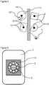
- FIG. 5 shows a schematic drawing of different types of mountings (13) surroundings the axis (2) of multiple transport rollers.
- the rotation of the mounting is reduced or prevented by means of fixation or choosing a specific outer form of said mountings (13).
- On the top left the mounting provides a round form. Rotation of said mounting (13) is prevented by a fixation (12).
- Said mounting (13) is connected to the conductive rail (11) using a cable (10), which in turn is connected to the grounding (4).
- the other three mountings (13) bottom left, bottom right and top right
- a conductive path is established allowing the charges to be conducted from the axis (2) to the conductive rail (11).
- Figure 6 shows a schematic drawing of a cross section of a rolling-element bearing providing an inner part (14) containing rolling elements (3) and outer part (7).
- the inner part (14) is surrounding the axis (2) of a transport roller.
- Figure 7 shows a schematic drawing of a side view of the rolling-element bearing of Figure 6 containing rolling elements (3), inner bearing (5) and outer bearing (6) of the inner part (14), and outer part (7) surrounding the axis (2) of the transport roller.
- rolling elements (3) are shown by means of discontinuous lines.
- Figure 8 exemplarily shows a schematic drawing of a rolling-element bearing containing rolling elements (3), inner part (14) and outer part (7) surrounding the axis (2) of a transport roller.
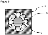
- Figure 9 shows the schematic drawing of another embodiment of the mounting similar to the mounting of Figure 6 showing the rolling elements (3) and the inner part (14) surrounding the axis (2) of the transport roller.
- the mounting provides no outer part.
- Figure 10 shows a schematic drawing of an electrostatic discharge unit containing multiple transport rollers (1), a substrate (15) and a gas supply element (16).
- the substrate is transported between the transport rollers (1) being arranged below and above the transport plane.
- the transport rollers (1) are arranged only below the substrate (15), wherein the gas supply element (16) directs a gas stream onto the surface of said substrate (15).
- FIG 11 shows a schematic drawing of an inventive module (20) containing transport roller systems (18) for transporting the substrate (15) through said module (20).
- transport roller systems (18) for transporting the substrate (15) through said module (20).
- the transport roller systems (18) are reduced to a circle representing the mounting (13) on the front side and the transport roller (1) behind it.
- the substrate (15) is transported between the transport rollers (1) being arranged above and below the transport plane, wherein the charges accumulating on their surfaces are conducted from the mounting (13) of the corresponding transport rollers system (18) to a conductive rail (11), a conductive frame (17) or a combination of a conductive rail and conductive frame (19) to the grounding (4).
- Figure 12 shows a schematic drawing of a module (20) like shown in Figure 11 viewed from the opposing side.
- gear wheels (22) are shown used to rotate the transport rollers (1).
- Said gear wheels are moved either directly or indirectly be a propulsion element (21) as shown in Figure 12 .
- Such propulsion element (21) generalized by a gear wheel without filling in Figure 12 introduces a movement into the row of gear wheels (22) which on the other hand rotate the transport rollers (1) transporting the substrate (15).
- the gear wheels (22) below and above the transport plane contain separate propulsion elements (21), however, the propulsion of all gear wheels (22) might also result from a single propulsion element (21).
- Figure 13 shows schematic drawing of an exemplary module (20) as shown in Figures 11 and 12 viewed from the top. For sake of simplification only one transport roller (1) has been labelled.
- the substrate (15) is moved through the module (20), wherein Figure 13 shows said substrate (15) being partially covered by some transport rollers (1).
- a gas supply element (16) Arranged next to the substrate (15) is a gas supply element (16) for directing a gas stream onto the surface of the substrate (15).
Landscapes
- Elimination Of Static Electricity (AREA)
- Rollers For Roller Conveyors For Transfer (AREA)
- Container, Conveyance, Adherence, Positioning, Of Wafer (AREA)
Claims (13)
- Elektrostatische Entladungseinheit, die mindestens eine elektrostatische Entladungsuntereinheit enthält,
wobei die mindestens eine elektrostatische Entladungsuntereinheit mindestens ein Transportwalzensystem (18) und mindestens eine Entladungsstrecke enthält,
wobei jedes Transportwalzensystem (18) unabhängig voneinander eine Transportwalze (1) und mindestens eine ein Wälzlager (23) enthaltende Halterung (13) enthält,
wobei die Transportwalzen (1) aus Metalltransportwalzen (1) oder polymerbeschichteten Metalltransportwalzen (1) ausgewählt sind,
und wobei die elektrostatische Entladungsuntereinheit angepasst ist, die Ladung von der Oberfläche der Transportwalze (1) durch das Wälzlager zur Entladungsstrecke zu leiten; wobei der elektrische Widerstand der Halterung, die angepasst ist, die Ladungen zur Erdung zu leiten, im Bereich von 103 bis 109 Ohm liegt; und wobei das Wälzlager ein Kugellager ist. - Elektrostatische Entladungseinheit nach Anspruch 1, wobei das Wälzlager (23) ein organisches Polymer enthält, und
wobei die elektrostatische Entladungseinheit angepasst ist, die Ladung von der Oberfläche der Transportwalze (1) durch das organische Polymer des Wälzlagers (23) zu der Entladungsstrecke zu leiten. - Elektrostatische Entladungseinheit nach einem der Ansprüche 1 bis 2, wobei die elektrostatische Entladungseinheit mindestens 3 elektrostatische Entladungsuntereinheiten enthält, die jeweils unabhängig voneinander 1, 2, 3, 4, 5 oder 6 Transportwalzensysteme (18) enthalten.
- Elektrostatische Entladungseinheit nach einem der Ansprüche 1 bis 3, wobei mindestens eine der Halterungen (13) der elektrostatischen Entladungsuntereinheiten der elektrostatischen Entladungseinheit mit einer leitenden Schiene (11), einem leitenden Rahmen (17) oder Kombinationen davon verbunden ist und wobei die leitende Schiene (11), der leitende Rahmen (17) oder Kombinationen davon geerdet sind.
- Elektrostatische Entladungseinheit nach Anspruch 4, wobei die leitende Schiene (11), der leitende Rahmen (17) oder Kombinationen davon aus Metall hergestellt sind.
- Elektrostatische Entladungseinheit nach einem der Ansprüche 2 bis 5, wobei das organische Polymer des Wälzlagers (23) ein selbstschmierendes organisches Polymer ist
- Elektrostatische Entladungseinheit nach einem der Ansprüche 1 bis 6, wobei die Anzahl der Transportwalzensysteme (18) mindestens das 1,3-Fache der Anzahl der Entladungsstrecken beträgt.
- Elektrostatische Entladungseinheit nach einem der Ansprüche 1 bis 7, wobei mindestens 3 elektrostatische Entladungsuntereinheiten nebeneinander angeordnet sind, wobei höchstens eine Transportwalze (1), die kein Bestandteil einer elektrostatischen Entladungsuntereinheit ist, zwischen den Transportwalzen (1) unter der Transportebene der elektrostatischen Entladungsuntereinheiten angeordnet ist.
- Elektrostatische Entladungseinheit nach einem der Ansprüche 1 bis 8, wobei die durchschnittliche Dicke der organischen Polymerbeschichtung der polymerbeschichteten Metalltransportwalzen (1), die zum Kontakt mit dem Substrat angepasst sind, weniger als 5 mm beträgt.
- Elektrostatische Entladungseinheit nach einem der Ansprüche 1 bis 9, wobei sich mindestens ein Gasversorgungselement (16) um die Transportwalzen (1) herum befindet.
- Modul (20) einer Behandlungsvorrichtung, das ein horizontales Transportsystem zum Transportieren eines Substrats (15) enthält, wobei das horizontale Transportsystem mindestens eine elektrostatische Entladungseinheit nach einem der Ansprüche 1 bis 10 enthält.
- Verfahren zum elektrischen Entladen eines Substrats (15), wobei das Substrat (15) mit mindestens einer elektrischen Entladeeinheit nach einem der Ansprüche 1 bis 10 oder mindestens einem Modul (20) nach Anspruch 11 transportiert wird.
- Verwendung mindestens einer elektrischen Entladungseinheit nach einem der Ansprüche 1 bis 10 oder mindestens eines Moduls (20) nach Anspruch 11 zur Herstellung einer gedruckten Leiterplatte, einer gedruckten Schaltungsfolie, eines Halbleiterwafers, einer Solarzelle oder einer photoelektrischen Zelle.
Priority Applications (6)
| Application Number | Priority Date | Filing Date | Title |
|---|---|---|---|
| EP16172947.0A EP3252804B1 (de) | 2016-06-03 | 2016-06-03 | Einheit zur elektrostatischen entladung |
| PCT/EP2017/062103 WO2017207300A1 (en) | 2016-06-03 | 2017-05-19 | Electrostatic discharge unit |
| JP2018562542A JP6952723B2 (ja) | 2016-06-03 | 2017-05-19 | 静電気放電ユニット |
| KR1020187035650A KR102339204B1 (ko) | 2016-06-03 | 2017-05-19 | 정전기 방전 유닛 |
| CN201780032971.6A CN109196633B (zh) | 2016-06-03 | 2017-05-19 | 静电放电单元 |
| TW106118205A TWI639545B (zh) | 2016-06-03 | 2017-06-02 | 靜電放電單元,包含其之處理裝置之模組,使用其使基板放電之方法及其用途 |
Applications Claiming Priority (1)
| Application Number | Priority Date | Filing Date | Title |
|---|---|---|---|
| EP16172947.0A EP3252804B1 (de) | 2016-06-03 | 2016-06-03 | Einheit zur elektrostatischen entladung |
Publications (2)
| Publication Number | Publication Date |
|---|---|
| EP3252804A1 EP3252804A1 (de) | 2017-12-06 |
| EP3252804B1 true EP3252804B1 (de) | 2021-05-19 |
Family
ID=56368762
Family Applications (1)
| Application Number | Title | Priority Date | Filing Date |
|---|---|---|---|
| EP16172947.0A Active EP3252804B1 (de) | 2016-06-03 | 2016-06-03 | Einheit zur elektrostatischen entladung |
Country Status (6)
| Country | Link |
|---|---|
| EP (1) | EP3252804B1 (de) |
| JP (1) | JP6952723B2 (de) |
| KR (1) | KR102339204B1 (de) |
| CN (1) | CN109196633B (de) |
| TW (1) | TWI639545B (de) |
| WO (1) | WO2017207300A1 (de) |
Families Citing this family (2)
| Publication number | Priority date | Publication date | Assignee | Title |
|---|---|---|---|---|
| JP7102778B2 (ja) * | 2018-02-27 | 2022-07-20 | セイコーエプソン株式会社 | 時計用ムーブメントおよび時計 |
| JP7130982B2 (ja) | 2018-02-27 | 2022-09-06 | セイコーエプソン株式会社 | 時計用ムーブメントおよび時計 |
Family Cites Families (14)
| Publication number | Priority date | Publication date | Assignee | Title |
|---|---|---|---|---|
| JPH0982486A (ja) * | 1995-09-07 | 1997-03-28 | Fuji Photo Film Co Ltd | ウエブの除電装置 |
| JP2002193579A (ja) * | 2000-12-26 | 2002-07-10 | Hitachi Building Systems Co Ltd | 乗客コンベア移動手摺のガイドローラ |
| JP4512441B2 (ja) * | 2004-07-30 | 2010-07-28 | 株式会社日本設計工業 | 基板の搬送装置 |
| TW200708204A (en) * | 2005-08-11 | 2007-02-16 | Chunghwa Picture Tubes Ltd | Method for eliminating electrostatic discharge |
| KR101231841B1 (ko) * | 2005-12-29 | 2013-02-08 | 엘지디스플레이 주식회사 | 반송계 |
| JP2007255712A (ja) * | 2006-03-21 | 2007-10-04 | Roller Bearing Co Of America Inc | ライナー及び表面処理面を有するチタン球面滑り軸受け |
| CN100508156C (zh) * | 2006-04-28 | 2009-07-01 | 友达光电股份有限公司 | 一种用于消除静电的系统 |
| JP2010024042A (ja) * | 2008-07-24 | 2010-02-04 | Shibaura Mechatronics Corp | 基板の搬送装置及び処理装置 |
| KR20100037375A (ko) * | 2008-10-01 | 2010-04-09 | 김경환 | 가로등 접지저항 측정 시스템 |
| JP5418505B2 (ja) * | 2009-02-03 | 2014-02-19 | コニカミノルタ株式会社 | 有機エレクトロニクス素子及びその製造方法 |
| DE102010000211A1 (de) | 2010-01-26 | 2011-07-28 | Atotech Deutschland GmbH, 90537 | Vorrichtung zum Transport von plattenförmigen Substraten in einer Anlage zur chemischen und/oder elektrochemischen Behandlung |
| KR101870162B1 (ko) * | 2011-10-07 | 2018-06-26 | 엘지디스플레이 주식회사 | 기판 이송 장치 및 그를 이용한 박막증착 장치 |
| KR20150016756A (ko) * | 2013-08-05 | 2015-02-13 | 삼성디스플레이 주식회사 | 기판 이송 장치 |
| KR101401025B1 (ko) * | 2013-12-23 | 2014-05-30 | (주)누리시스템 | 기판 이송용 회전롤러의 접지장치 |
-
2016
- 2016-06-03 EP EP16172947.0A patent/EP3252804B1/de active Active
-
2017
- 2017-05-19 KR KR1020187035650A patent/KR102339204B1/ko active Active
- 2017-05-19 JP JP2018562542A patent/JP6952723B2/ja active Active
- 2017-05-19 CN CN201780032971.6A patent/CN109196633B/zh active Active
- 2017-05-19 WO PCT/EP2017/062103 patent/WO2017207300A1/en not_active Ceased
- 2017-06-02 TW TW106118205A patent/TWI639545B/zh active
Also Published As
| Publication number | Publication date |
|---|---|
| TWI639545B (zh) | 2018-11-01 |
| CN109196633A (zh) | 2019-01-11 |
| JP6952723B2 (ja) | 2021-10-20 |
| TW201802015A (zh) | 2018-01-16 |
| KR20190015297A (ko) | 2019-02-13 |
| WO2017207300A1 (en) | 2017-12-07 |
| EP3252804A1 (de) | 2017-12-06 |
| KR102339204B1 (ko) | 2021-12-14 |
| CN109196633B (zh) | 2022-03-25 |
| JP2019519891A (ja) | 2019-07-11 |
Similar Documents
| Publication | Publication Date | Title |
|---|---|---|
| EP3252804A1 (de) | Einheit zum elektrostatischen entladung | |
| CN101275267B (zh) | 改良厚度均匀性的电镀装置与电镀方法 | |
| US20090134034A1 (en) | Prevention of substrate edge plating in a fountain plating process | |
| CN101165870A (zh) | 用于处理扁平、易碎基体的装置 | |
| TWI414642B (zh) | Apparatus and method for making electrical contact with a flat article in a continuous processing device | |
| JP2009534525A (ja) | 電解コーティング装置及び電解コーティング方法 | |
| US20240247396A1 (en) | Leakage determination method and plating apparatus | |
| WO2003106740A1 (ja) | めっき被膜付きフィルムの製造方法、めっき用 陰極ロール、ならびに、回路基板の製造方法 | |
| CN103290460A (zh) | 与阳极夹一起使用的导电带以及阳极夹 | |
| US20240218552A1 (en) | Plating apparatus and contact cleaning method | |
| JP5080157B2 (ja) | 平坦な壊れやすい基板を処理するための装置 | |
| WO2014001151A1 (en) | Continuous reel-to-reel arrangement | |
| US11097913B2 (en) | Transport roller | |
| JP2012528058A (ja) | 物品を搬送する搬送ローラ | |
| KR102010679B1 (ko) | 갈바닉 금속 디포지션을 위한 수평 갈바닉 도금 프로세싱 라인의 갈바닉 도금 디바이스 및 그것의 사용 | |
| CN116020692B (zh) | 硅片钝化系统及硅片钝化系统的工作方法 | |
| CN219891352U (zh) | 一种漆包线在线高压绝缘检测机构 | |
| TW200525051A (en) | Method and apparatus for carrying and treating flat material without contact by continuous equipment | |
| CN110760922A (zh) | 退锡液、去除基材上的含锡层的方法和回收锡的方法 | |
| KR101740208B1 (ko) | 대형 기판의 수평 습식 화학 처리를 위한 장치의 처리 모듈 | |
| CN212161781U (zh) | 一种真空吸盘及硅片运送装置 | |
| JP2019519891A5 (de) | ||
| CN220643331U (zh) | 电镀装置 | |
| CN218339407U (zh) | 一种顺酐高精空气过滤装置 | |
| JP2010519413A (ja) | 液体で帯状の基材を処理する装置 |
Legal Events
| Date | Code | Title | Description |
|---|---|---|---|
| PUAI | Public reference made under article 153(3) epc to a published international application that has entered the european phase |
Free format text: ORIGINAL CODE: 0009012 |
|
| STAA | Information on the status of an ep patent application or granted ep patent |
Free format text: STATUS: THE APPLICATION HAS BEEN PUBLISHED |
|
| AK | Designated contracting states |
Kind code of ref document: A1 Designated state(s): AL AT BE BG CH CY CZ DE DK EE ES FI FR GB GR HR HU IE IS IT LI LT LU LV MC MK MT NL NO PL PT RO RS SE SI SK SM TR |
|
| AX | Request for extension of the european patent |
Extension state: BA ME |
|
| STAA | Information on the status of an ep patent application or granted ep patent |
Free format text: STATUS: REQUEST FOR EXAMINATION WAS MADE |
|
| 17P | Request for examination filed |
Effective date: 20180606 |
|
| RBV | Designated contracting states (corrected) |
Designated state(s): AL AT BE BG CH CY CZ DE DK EE ES FI FR GB GR HR HU IE IS IT LI LT LU LV MC MK MT NL NO PL PT RO RS SE SI SK SM TR |
|
| GRAP | Despatch of communication of intention to grant a patent |
Free format text: ORIGINAL CODE: EPIDOSNIGR1 |
|
| STAA | Information on the status of an ep patent application or granted ep patent |
Free format text: STATUS: GRANT OF PATENT IS INTENDED |
|
| INTG | Intention to grant announced |
Effective date: 20210312 |
|
| GRAS | Grant fee paid |
Free format text: ORIGINAL CODE: EPIDOSNIGR3 |
|
| GRAA | (expected) grant |
Free format text: ORIGINAL CODE: 0009210 |
|
| STAA | Information on the status of an ep patent application or granted ep patent |
Free format text: STATUS: THE PATENT HAS BEEN GRANTED |
|
| AK | Designated contracting states |
Kind code of ref document: B1 Designated state(s): AL AT BE BG CH CY CZ DE DK EE ES FI FR GB GR HR HU IE IS IT LI LT LU LV MC MK MT NL NO PL PT RO RS SE SI SK SM TR |
|
| REG | Reference to a national code |
Ref country code: GB Ref legal event code: FG4D |
|
| REG | Reference to a national code |
Ref country code: CH Ref legal event code: EP |
|
| REG | Reference to a national code |
Ref country code: DE Ref legal event code: R096 Ref document number: 602016057949 Country of ref document: DE |
|
| REG | Reference to a national code |
Ref country code: AT Ref legal event code: REF Ref document number: 1394817 Country of ref document: AT Kind code of ref document: T Effective date: 20210615 |
|
| REG | Reference to a national code |
Ref country code: IE Ref legal event code: FG4D |
|
| REG | Reference to a national code |
Ref country code: LT Ref legal event code: MG9D |
|
| REG | Reference to a national code |
Ref country code: NL Ref legal event code: MP Effective date: 20210519 |
|
| PG25 | Lapsed in a contracting state [announced via postgrant information from national office to epo] |
Ref country code: HR Free format text: LAPSE BECAUSE OF FAILURE TO SUBMIT A TRANSLATION OF THE DESCRIPTION OR TO PAY THE FEE WITHIN THE PRESCRIBED TIME-LIMIT Effective date: 20210519 Ref country code: BG Free format text: LAPSE BECAUSE OF FAILURE TO SUBMIT A TRANSLATION OF THE DESCRIPTION OR TO PAY THE FEE WITHIN THE PRESCRIBED TIME-LIMIT Effective date: 20210819 Ref country code: LT Free format text: LAPSE BECAUSE OF FAILURE TO SUBMIT A TRANSLATION OF THE DESCRIPTION OR TO PAY THE FEE WITHIN THE PRESCRIBED TIME-LIMIT Effective date: 20210519 Ref country code: FI Free format text: LAPSE BECAUSE OF FAILURE TO SUBMIT A TRANSLATION OF THE DESCRIPTION OR TO PAY THE FEE WITHIN THE PRESCRIBED TIME-LIMIT Effective date: 20210519 |
|
| PG25 | Lapsed in a contracting state [announced via postgrant information from national office to epo] |
Ref country code: RS Free format text: LAPSE BECAUSE OF FAILURE TO SUBMIT A TRANSLATION OF THE DESCRIPTION OR TO PAY THE FEE WITHIN THE PRESCRIBED TIME-LIMIT Effective date: 20210519 Ref country code: SE Free format text: LAPSE BECAUSE OF FAILURE TO SUBMIT A TRANSLATION OF THE DESCRIPTION OR TO PAY THE FEE WITHIN THE PRESCRIBED TIME-LIMIT Effective date: 20210519 Ref country code: PL Free format text: LAPSE BECAUSE OF FAILURE TO SUBMIT A TRANSLATION OF THE DESCRIPTION OR TO PAY THE FEE WITHIN THE PRESCRIBED TIME-LIMIT Effective date: 20210519 Ref country code: NO Free format text: LAPSE BECAUSE OF FAILURE TO SUBMIT A TRANSLATION OF THE DESCRIPTION OR TO PAY THE FEE WITHIN THE PRESCRIBED TIME-LIMIT Effective date: 20210819 Ref country code: PT Free format text: LAPSE BECAUSE OF FAILURE TO SUBMIT A TRANSLATION OF THE DESCRIPTION OR TO PAY THE FEE WITHIN THE PRESCRIBED TIME-LIMIT Effective date: 20210920 Ref country code: LV Free format text: LAPSE BECAUSE OF FAILURE TO SUBMIT A TRANSLATION OF THE DESCRIPTION OR TO PAY THE FEE WITHIN THE PRESCRIBED TIME-LIMIT Effective date: 20210519 Ref country code: IS Free format text: LAPSE BECAUSE OF FAILURE TO SUBMIT A TRANSLATION OF THE DESCRIPTION OR TO PAY THE FEE WITHIN THE PRESCRIBED TIME-LIMIT Effective date: 20210919 Ref country code: GR Free format text: LAPSE BECAUSE OF FAILURE TO SUBMIT A TRANSLATION OF THE DESCRIPTION OR TO PAY THE FEE WITHIN THE PRESCRIBED TIME-LIMIT Effective date: 20210820 |
|
| PG25 | Lapsed in a contracting state [announced via postgrant information from national office to epo] |
Ref country code: NL Free format text: LAPSE BECAUSE OF FAILURE TO SUBMIT A TRANSLATION OF THE DESCRIPTION OR TO PAY THE FEE WITHIN THE PRESCRIBED TIME-LIMIT Effective date: 20210519 |
|
| PG25 | Lapsed in a contracting state [announced via postgrant information from national office to epo] |
Ref country code: EE Free format text: LAPSE BECAUSE OF FAILURE TO SUBMIT A TRANSLATION OF THE DESCRIPTION OR TO PAY THE FEE WITHIN THE PRESCRIBED TIME-LIMIT Effective date: 20210519 Ref country code: CZ Free format text: LAPSE BECAUSE OF FAILURE TO SUBMIT A TRANSLATION OF THE DESCRIPTION OR TO PAY THE FEE WITHIN THE PRESCRIBED TIME-LIMIT Effective date: 20210519 Ref country code: DK Free format text: LAPSE BECAUSE OF FAILURE TO SUBMIT A TRANSLATION OF THE DESCRIPTION OR TO PAY THE FEE WITHIN THE PRESCRIBED TIME-LIMIT Effective date: 20210519 Ref country code: SM Free format text: LAPSE BECAUSE OF FAILURE TO SUBMIT A TRANSLATION OF THE DESCRIPTION OR TO PAY THE FEE WITHIN THE PRESCRIBED TIME-LIMIT Effective date: 20210519 Ref country code: SK Free format text: LAPSE BECAUSE OF FAILURE TO SUBMIT A TRANSLATION OF THE DESCRIPTION OR TO PAY THE FEE WITHIN THE PRESCRIBED TIME-LIMIT Effective date: 20210519 Ref country code: RO Free format text: LAPSE BECAUSE OF FAILURE TO SUBMIT A TRANSLATION OF THE DESCRIPTION OR TO PAY THE FEE WITHIN THE PRESCRIBED TIME-LIMIT Effective date: 20210519 Ref country code: ES Free format text: LAPSE BECAUSE OF FAILURE TO SUBMIT A TRANSLATION OF THE DESCRIPTION OR TO PAY THE FEE WITHIN THE PRESCRIBED TIME-LIMIT Effective date: 20210519 |
|
| REG | Reference to a national code |
Ref country code: CH Ref legal event code: PL |
|
| REG | Reference to a national code |
Ref country code: DE Ref legal event code: R097 Ref document number: 602016057949 Country of ref document: DE |
|
| RAP4 | Party data changed (patent owner data changed or rights of a patent transferred) |
Owner name: ATOTECH DEUTSCHLAND GMBH & CO. KG |
|
| REG | Reference to a national code |
Ref country code: BE Ref legal event code: MM Effective date: 20210630 |
|
| PLBE | No opposition filed within time limit |
Free format text: ORIGINAL CODE: 0009261 |
|
| STAA | Information on the status of an ep patent application or granted ep patent |
Free format text: STATUS: NO OPPOSITION FILED WITHIN TIME LIMIT |
|
| PG25 | Lapsed in a contracting state [announced via postgrant information from national office to epo] |
Ref country code: MC Free format text: LAPSE BECAUSE OF FAILURE TO SUBMIT A TRANSLATION OF THE DESCRIPTION OR TO PAY THE FEE WITHIN THE PRESCRIBED TIME-LIMIT Effective date: 20210519 Ref country code: LU Free format text: LAPSE BECAUSE OF NON-PAYMENT OF DUE FEES Effective date: 20210603 |
|
| 26N | No opposition filed |
Effective date: 20220222 |
|
| GBPC | Gb: european patent ceased through non-payment of renewal fee |
Effective date: 20210819 |
|
| PG25 | Lapsed in a contracting state [announced via postgrant information from national office to epo] |
Ref country code: LI Free format text: LAPSE BECAUSE OF NON-PAYMENT OF DUE FEES Effective date: 20210630 Ref country code: IE Free format text: LAPSE BECAUSE OF NON-PAYMENT OF DUE FEES Effective date: 20210603 Ref country code: CH Free format text: LAPSE BECAUSE OF NON-PAYMENT OF DUE FEES Effective date: 20210630 |
|
| PG25 | Lapsed in a contracting state [announced via postgrant information from national office to epo] |
Ref country code: IS Free format text: LAPSE BECAUSE OF FAILURE TO SUBMIT A TRANSLATION OF THE DESCRIPTION OR TO PAY THE FEE WITHIN THE PRESCRIBED TIME-LIMIT Effective date: 20210919 Ref country code: FR Free format text: LAPSE BECAUSE OF NON-PAYMENT OF DUE FEES Effective date: 20210719 Ref country code: AL Free format text: LAPSE BECAUSE OF FAILURE TO SUBMIT A TRANSLATION OF THE DESCRIPTION OR TO PAY THE FEE WITHIN THE PRESCRIBED TIME-LIMIT Effective date: 20210519 |
|
| PG25 | Lapsed in a contracting state [announced via postgrant information from national office to epo] |
Ref country code: IT Free format text: LAPSE BECAUSE OF FAILURE TO SUBMIT A TRANSLATION OF THE DESCRIPTION OR TO PAY THE FEE WITHIN THE PRESCRIBED TIME-LIMIT Effective date: 20210519 Ref country code: GB Free format text: LAPSE BECAUSE OF NON-PAYMENT OF DUE FEES Effective date: 20210819 Ref country code: BE Free format text: LAPSE BECAUSE OF NON-PAYMENT OF DUE FEES Effective date: 20210630 |
|
| REG | Reference to a national code |
Ref country code: AT Ref legal event code: UEP Ref document number: 1394817 Country of ref document: AT Kind code of ref document: T Effective date: 20210519 |
|
| PG25 | Lapsed in a contracting state [announced via postgrant information from national office to epo] |
Ref country code: HU Free format text: LAPSE BECAUSE OF FAILURE TO SUBMIT A TRANSLATION OF THE DESCRIPTION OR TO PAY THE FEE WITHIN THE PRESCRIBED TIME-LIMIT; INVALID AB INITIO Effective date: 20160603 |
|
| PG25 | Lapsed in a contracting state [announced via postgrant information from national office to epo] |
Ref country code: CY Free format text: LAPSE BECAUSE OF FAILURE TO SUBMIT A TRANSLATION OF THE DESCRIPTION OR TO PAY THE FEE WITHIN THE PRESCRIBED TIME-LIMIT Effective date: 20210519 |
|
| PG25 | Lapsed in a contracting state [announced via postgrant information from national office to epo] |
Ref country code: MK Free format text: LAPSE BECAUSE OF FAILURE TO SUBMIT A TRANSLATION OF THE DESCRIPTION OR TO PAY THE FEE WITHIN THE PRESCRIBED TIME-LIMIT Effective date: 20210519 |
|
| PG25 | Lapsed in a contracting state [announced via postgrant information from national office to epo] |
Ref country code: TR Free format text: LAPSE BECAUSE OF FAILURE TO SUBMIT A TRANSLATION OF THE DESCRIPTION OR TO PAY THE FEE WITHIN THE PRESCRIBED TIME-LIMIT Effective date: 20210519 |
|
| PG25 | Lapsed in a contracting state [announced via postgrant information from national office to epo] |
Ref country code: MT Free format text: LAPSE BECAUSE OF FAILURE TO SUBMIT A TRANSLATION OF THE DESCRIPTION OR TO PAY THE FEE WITHIN THE PRESCRIBED TIME-LIMIT Effective date: 20210519 |
|
| PGFP | Annual fee paid to national office [announced via postgrant information from national office to epo] |
Ref country code: DE Payment date: 20250626 Year of fee payment: 10 |
|
| PGFP | Annual fee paid to national office [announced via postgrant information from national office to epo] |
Ref country code: AT Payment date: 20250617 Year of fee payment: 10 |
|
| REG | Reference to a national code |
Ref country code: DE Ref legal event code: R079 Ref document number: 602016057949 Country of ref document: DE Free format text: PREVIOUS MAIN CLASS: H01L0021670000 Ipc: H10P0072000000 |