EP3248569A1 - Porte-fil dentaire - Google Patents
Porte-fil dentaire Download PDFInfo
- Publication number
- EP3248569A1 EP3248569A1 EP17175963.2A EP17175963A EP3248569A1 EP 3248569 A1 EP3248569 A1 EP 3248569A1 EP 17175963 A EP17175963 A EP 17175963A EP 3248569 A1 EP3248569 A1 EP 3248569A1
- Authority
- EP
- European Patent Office
- Prior art keywords
- holder
- handle body
- toothpick
- flosser
- fins
- Prior art date
- Legal status (The legal status is an assumption and is not a legal conclusion. Google has not performed a legal analysis and makes no representation as to the accuracy of the status listed.)
- Granted
Links
- 238000004140 cleaning Methods 0.000 claims abstract description 255
- 244000153158 Ammi visnaga Species 0.000 claims description 142
- 235000010585 Ammi visnaga Nutrition 0.000 claims description 136
- 238000001746 injection moulding Methods 0.000 claims description 120
- 239000000463 material Substances 0.000 claims description 100
- 230000001681 protective effect Effects 0.000 claims description 11
- 230000004224 protection Effects 0.000 claims description 7
- 230000003993 interaction Effects 0.000 claims description 2
- 238000013016 damping Methods 0.000 description 68
- 239000000835 fiber Substances 0.000 description 55
- 241000628997 Flos Species 0.000 description 41
- 229920003023 plastic Polymers 0.000 description 41
- 239000004033 plastic Substances 0.000 description 41
- 238000004519 manufacturing process Methods 0.000 description 36
- 239000013543 active substance Substances 0.000 description 35
- 238000005498 polishing Methods 0.000 description 34
- 238000002347 injection Methods 0.000 description 33
- 239000007924 injection Substances 0.000 description 33
- 238000000465 moulding Methods 0.000 description 29
- 238000000034 method Methods 0.000 description 27
- 238000004873 anchoring Methods 0.000 description 24
- -1 Tricolsan Chemical compound 0.000 description 19
- 230000008569 process Effects 0.000 description 19
- 241000446313 Lamella Species 0.000 description 17
- 238000001816 cooling Methods 0.000 description 17
- 238000005516 engineering process Methods 0.000 description 16
- 241001290722 Odontonema Species 0.000 description 14
- 229920002647 polyamide Polymers 0.000 description 14
- 229920000573 polyethylene Polymers 0.000 description 13
- 239000007787 solid Substances 0.000 description 13
- 230000007704 transition Effects 0.000 description 13
- 239000004952 Polyamide Substances 0.000 description 12
- 229920001971 elastomer Polymers 0.000 description 12
- 238000012546 transfer Methods 0.000 description 12
- 239000000806 elastomer Substances 0.000 description 11
- 239000004698 Polyethylene Substances 0.000 description 10
- 230000000694 effects Effects 0.000 description 10
- 238000001125 extrusion Methods 0.000 description 10
- 239000007779 soft material Substances 0.000 description 10
- 230000009975 flexible effect Effects 0.000 description 9
- 239000011248 coating agent Substances 0.000 description 8
- 238000000576 coating method Methods 0.000 description 8
- 238000005520 cutting process Methods 0.000 description 8
- 238000004080 punching Methods 0.000 description 8
- 239000012528 membrane Substances 0.000 description 7
- 230000036961 partial effect Effects 0.000 description 7
- DNIAPMSPPWPWGF-UHFFFAOYSA-N Propylene glycol Chemical compound CC(O)CO DNIAPMSPPWPWGF-UHFFFAOYSA-N 0.000 description 6
- 238000004026 adhesive bonding Methods 0.000 description 6
- KRKNYBCHXYNGOX-UHFFFAOYSA-N citric acid Chemical compound OC(=O)CC(O)(C(O)=O)CC(O)=O KRKNYBCHXYNGOX-UHFFFAOYSA-N 0.000 description 6
- 210000003811 finger Anatomy 0.000 description 6
- 229920001155 polypropylene Polymers 0.000 description 6
- PEDCQBHIVMGVHV-UHFFFAOYSA-N Glycerine Chemical compound OCC(O)CO PEDCQBHIVMGVHV-UHFFFAOYSA-N 0.000 description 5
- 238000004061 bleaching Methods 0.000 description 5
- 229920000728 polyester Polymers 0.000 description 5
- 238000012545 processing Methods 0.000 description 5
- PUZPDOWCWNUUKD-UHFFFAOYSA-M sodium fluoride Chemical compound [F-].[Na+] PUZPDOWCWNUUKD-UHFFFAOYSA-M 0.000 description 5
- 239000000126 substance Substances 0.000 description 5
- NBIIXXVUZAFLBC-UHFFFAOYSA-N Phosphoric acid Chemical compound OP(O)(O)=O NBIIXXVUZAFLBC-UHFFFAOYSA-N 0.000 description 4
- CDBYLPFSWZWCQE-UHFFFAOYSA-L Sodium Carbonate Chemical compound [Na+].[Na+].[O-]C([O-])=O CDBYLPFSWZWCQE-UHFFFAOYSA-L 0.000 description 4
- PPBRXRYQALVLMV-UHFFFAOYSA-N Styrene Chemical compound C=CC1=CC=CC=C1 PPBRXRYQALVLMV-UHFFFAOYSA-N 0.000 description 4
- 239000004480 active ingredient Substances 0.000 description 4
- 230000008901 benefit Effects 0.000 description 4
- 229920002678 cellulose Polymers 0.000 description 4
- 239000001913 cellulose Substances 0.000 description 4
- 230000008859 change Effects 0.000 description 4
- 229920001903 high density polyethylene Polymers 0.000 description 4
- 229920003229 poly(methyl methacrylate) Polymers 0.000 description 4
- 229920000642 polymer Polymers 0.000 description 4
- 229920006324 polyoxymethylene Polymers 0.000 description 4
- 229920001343 polytetrafluoroethylene Polymers 0.000 description 4
- 239000004810 polytetrafluoroethylene Substances 0.000 description 4
- 229920002635 polyurethane Polymers 0.000 description 4
- 239000004814 polyurethane Substances 0.000 description 4
- BWHMMNNQKKPAPP-UHFFFAOYSA-L potassium carbonate Chemical compound [K+].[K+].[O-]C([O-])=O BWHMMNNQKKPAPP-UHFFFAOYSA-L 0.000 description 4
- 238000002360 preparation method Methods 0.000 description 4
- CVHZOJJKTDOEJC-UHFFFAOYSA-N saccharin Chemical compound C1=CC=C2C(=O)NS(=O)(=O)C2=C1 CVHZOJJKTDOEJC-UHFFFAOYSA-N 0.000 description 4
- 238000007493 shaping process Methods 0.000 description 4
- 238000005507 spraying Methods 0.000 description 4
- 239000004753 textile Substances 0.000 description 4
- 210000003813 thumb Anatomy 0.000 description 4
- 239000000606 toothpaste Substances 0.000 description 4
- 238000003466 welding Methods 0.000 description 4
- 229920000623 Cellulose acetate phthalate Polymers 0.000 description 3
- DQEFEBPAPFSJLV-UHFFFAOYSA-N Cellulose propionate Chemical compound CCC(=O)OCC1OC(OC(=O)CC)C(OC(=O)CC)C(OC(=O)CC)C1OC1C(OC(=O)CC)C(OC(=O)CC)C(OC(=O)CC)C(COC(=O)CC)O1 DQEFEBPAPFSJLV-UHFFFAOYSA-N 0.000 description 3
- MHAJPDPJQMAIIY-UHFFFAOYSA-N Hydrogen peroxide Chemical compound OO MHAJPDPJQMAIIY-UHFFFAOYSA-N 0.000 description 3
- GWEVSGVZZGPLCZ-UHFFFAOYSA-N Titan oxide Chemical compound O=[Ti]=O GWEVSGVZZGPLCZ-UHFFFAOYSA-N 0.000 description 3
- 230000001070 adhesive effect Effects 0.000 description 3
- 230000000844 anti-bacterial effect Effects 0.000 description 3
- 229920002301 cellulose acetate Polymers 0.000 description 3
- 229940081734 cellulose acetate phthalate Drugs 0.000 description 3
- 229920001727 cellulose butyrate Polymers 0.000 description 3
- 229920006218 cellulose propionate Polymers 0.000 description 3
- 239000003795 chemical substances by application Substances 0.000 description 3
- CVSVTCORWBXHQV-UHFFFAOYSA-N creatine Chemical compound NC(=[NH2+])N(C)CC([O-])=O CVSVTCORWBXHQV-UHFFFAOYSA-N 0.000 description 3
- 238000013461 design Methods 0.000 description 3
- 238000011161 development Methods 0.000 description 3
- 230000018109 developmental process Effects 0.000 description 3
- 238000005538 encapsulation Methods 0.000 description 3
- 230000003628 erosive effect Effects 0.000 description 3
- 239000011888 foil Substances 0.000 description 3
- 229920001684 low density polyethylene Polymers 0.000 description 3
- 239000004702 low-density polyethylene Substances 0.000 description 3
- 230000035515 penetration Effects 0.000 description 3
- 229920000139 polyethylene terephthalate Polymers 0.000 description 3
- 239000005020 polyethylene terephthalate Substances 0.000 description 3
- 230000002829 reductive effect Effects 0.000 description 3
- 235000013024 sodium fluoride Nutrition 0.000 description 3
- 239000011115 styrene butadiene Substances 0.000 description 3
- 229920001169 thermoplastic Polymers 0.000 description 3
- 239000004416 thermosoftening plastic Substances 0.000 description 3
- 229940034610 toothpaste Drugs 0.000 description 3
- JDCCCHBBXRQRGU-UHFFFAOYSA-N 5-phenylpenta-2,4-dienenitrile Chemical compound N#CC=CC=CC1=CC=CC=C1 JDCCCHBBXRQRGU-UHFFFAOYSA-N 0.000 description 2
- 0 CCC1C(CC)C(C*)CC1 Chemical compound CCC1C(CC)C(C*)CC1 0.000 description 2
- 229920002134 Carboxymethyl cellulose Polymers 0.000 description 2
- FBPFZTCFMRRESA-FSIIMWSLSA-N D-Glucitol Natural products OC[C@H](O)[C@H](O)[C@@H](O)[C@H](O)CO FBPFZTCFMRRESA-FSIIMWSLSA-N 0.000 description 2
- WQZGKKKJIJFFOK-GASJEMHNSA-N Glucose Natural products OC[C@H]1OC(O)[C@H](O)[C@@H](O)[C@@H]1O WQZGKKKJIJFFOK-GASJEMHNSA-N 0.000 description 2
- FYYHWMGAXLPEAU-UHFFFAOYSA-N Magnesium Chemical compound [Mg] FYYHWMGAXLPEAU-UHFFFAOYSA-N 0.000 description 2
- 229920002774 Maltodextrin Polymers 0.000 description 2
- 239000005913 Maltodextrin Substances 0.000 description 2
- 239000004743 Polypropylene Substances 0.000 description 2
- UIIMBOGNXHQVGW-DEQYMQKBSA-M Sodium bicarbonate-14C Chemical compound [Na+].O[14C]([O-])=O UIIMBOGNXHQVGW-DEQYMQKBSA-M 0.000 description 2
- DBMJMQXJHONAFJ-UHFFFAOYSA-M Sodium laurylsulphate Chemical compound [Na+].CCCCCCCCCCCCOS([O-])(=O)=O DBMJMQXJHONAFJ-UHFFFAOYSA-M 0.000 description 2
- 239000002174 Styrene-butadiene Substances 0.000 description 2
- 208000027418 Wounds and injury Diseases 0.000 description 2
- 239000004676 acrylonitrile butadiene styrene Substances 0.000 description 2
- 230000009471 action Effects 0.000 description 2
- PNEYBMLMFCGWSK-UHFFFAOYSA-N aluminium oxide Inorganic materials [O-2].[O-2].[O-2].[Al+3].[Al+3] PNEYBMLMFCGWSK-UHFFFAOYSA-N 0.000 description 2
- 229910000147 aluminium phosphate Inorganic materials 0.000 description 2
- 239000011324 bead Substances 0.000 description 2
- 238000005452 bending Methods 0.000 description 2
- 229920000704 biodegradable plastic Polymers 0.000 description 2
- MTAZNLWOLGHBHU-UHFFFAOYSA-N butadiene-styrene rubber Chemical compound C=CC=C.C=CC1=CC=CC=C1 MTAZNLWOLGHBHU-UHFFFAOYSA-N 0.000 description 2
- 239000001768 carboxy methyl cellulose Substances 0.000 description 2
- 235000010948 carboxy methyl cellulose Nutrition 0.000 description 2
- 239000012876 carrier material Substances 0.000 description 2
- 239000012459 cleaning agent Substances 0.000 description 2
- 229920001577 copolymer Polymers 0.000 description 2
- 230000006378 damage Effects 0.000 description 2
- 230000003247 decreasing effect Effects 0.000 description 2
- 230000001419 dependent effect Effects 0.000 description 2
- LRCFXGAMWKDGLA-UHFFFAOYSA-N dioxosilane;hydrate Chemical compound O.O=[Si]=O LRCFXGAMWKDGLA-UHFFFAOYSA-N 0.000 description 2
- 238000007598 dipping method Methods 0.000 description 2
- BNIILDVGGAEEIG-UHFFFAOYSA-L disodium hydrogen phosphate Chemical compound [Na+].[Na+].OP([O-])([O-])=O BNIILDVGGAEEIG-UHFFFAOYSA-L 0.000 description 2
- 235000019800 disodium phosphate Nutrition 0.000 description 2
- 239000013013 elastic material Substances 0.000 description 2
- 239000004744 fabric Substances 0.000 description 2
- 238000005562 fading Methods 0.000 description 2
- 230000002349 favourable effect Effects 0.000 description 2
- 238000011049 filling Methods 0.000 description 2
- 239000000796 flavoring agent Substances 0.000 description 2
- 235000019634 flavors Nutrition 0.000 description 2
- 230000009969 flowable effect Effects 0.000 description 2
- 230000006870 function Effects 0.000 description 2
- 230000014509 gene expression Effects 0.000 description 2
- 239000008103 glucose Substances 0.000 description 2
- 235000011187 glycerol Nutrition 0.000 description 2
- 238000005470 impregnation Methods 0.000 description 2
- 208000014674 injury Diseases 0.000 description 2
- 239000007788 liquid Substances 0.000 description 2
- 239000011777 magnesium Substances 0.000 description 2
- 229910052749 magnesium Inorganic materials 0.000 description 2
- 229940035034 maltodextrin Drugs 0.000 description 2
- 230000007246 mechanism Effects 0.000 description 2
- 238000002844 melting Methods 0.000 description 2
- 230000008018 melting Effects 0.000 description 2
- 239000002324 mouth wash Substances 0.000 description 2
- 229940051866 mouthwash Drugs 0.000 description 2
- 238000004806 packaging method and process Methods 0.000 description 2
- 229920001123 polycyclohexylenedimethylene terephthalate Polymers 0.000 description 2
- 229920000098 polyolefin Polymers 0.000 description 2
- 229920002223 polystyrene Polymers 0.000 description 2
- 229920000915 polyvinyl chloride Polymers 0.000 description 2
- 229910000027 potassium carbonate Inorganic materials 0.000 description 2
- 238000003825 pressing Methods 0.000 description 2
- 239000000047 product Substances 0.000 description 2
- 235000013772 propylene glycol Nutrition 0.000 description 2
- 229940081974 saccharin Drugs 0.000 description 2
- 235000019204 saccharin Nutrition 0.000 description 2
- 239000000901 saccharin and its Na,K and Ca salt Substances 0.000 description 2
- 229960004029 silicic acid Drugs 0.000 description 2
- WXMKPNITSTVMEF-UHFFFAOYSA-M sodium benzoate Chemical compound [Na+].[O-]C(=O)C1=CC=CC=C1 WXMKPNITSTVMEF-UHFFFAOYSA-M 0.000 description 2
- 235000010234 sodium benzoate Nutrition 0.000 description 2
- 239000004299 sodium benzoate Substances 0.000 description 2
- 229910000029 sodium carbonate Inorganic materials 0.000 description 2
- FQENQNTWSFEDLI-UHFFFAOYSA-J sodium diphosphate Chemical compound [Na+].[Na+].[Na+].[Na+].[O-]P([O-])(=O)OP([O-])([O-])=O FQENQNTWSFEDLI-UHFFFAOYSA-J 0.000 description 2
- 239000011775 sodium fluoride Substances 0.000 description 2
- GCLGEJMYGQKIIW-UHFFFAOYSA-H sodium hexametaphosphate Chemical compound [Na]OP1(=O)OP(=O)(O[Na])OP(=O)(O[Na])OP(=O)(O[Na])OP(=O)(O[Na])OP(=O)(O[Na])O1 GCLGEJMYGQKIIW-UHFFFAOYSA-H 0.000 description 2
- 235000019982 sodium hexametaphosphate Nutrition 0.000 description 2
- 235000019333 sodium laurylsulphate Nutrition 0.000 description 2
- RYYKJJJTJZKILX-UHFFFAOYSA-M sodium octadecanoate Chemical compound [Na+].CCCCCCCCCCCCCCCCCC([O-])=O RYYKJJJTJZKILX-UHFFFAOYSA-M 0.000 description 2
- 229960001922 sodium perborate Drugs 0.000 description 2
- 239000001488 sodium phosphate Substances 0.000 description 2
- YKLJGMBLPUQQOI-UHFFFAOYSA-M sodium;oxidooxy(oxo)borane Chemical compound [Na+].[O-]OB=O YKLJGMBLPUQQOI-UHFFFAOYSA-M 0.000 description 2
- 239000000600 sorbitol Substances 0.000 description 2
- 239000007921 spray Substances 0.000 description 2
- 229920000638 styrene acrylonitrile Polymers 0.000 description 2
- 229920003048 styrene butadiene rubber Polymers 0.000 description 2
- 235000019818 tetrasodium diphosphate Nutrition 0.000 description 2
- 239000001577 tetrasodium phosphonato phosphate Substances 0.000 description 2
- 229920002725 thermoplastic elastomer Polymers 0.000 description 2
- 235000010215 titanium dioxide Nutrition 0.000 description 2
- RYFMWSXOAZQYPI-UHFFFAOYSA-K trisodium phosphate Chemical compound [Na+].[Na+].[Na+].[O-]P([O-])([O-])=O RYFMWSXOAZQYPI-UHFFFAOYSA-K 0.000 description 2
- 235000019801 trisodium phosphate Nutrition 0.000 description 2
- 239000001993 wax Substances 0.000 description 2
- 230000003313 weakening effect Effects 0.000 description 2
- 230000002087 whitening effect Effects 0.000 description 2
- XGRSAFKZAGGXJV-UHFFFAOYSA-N 3-azaniumyl-3-cyclohexylpropanoate Chemical compound OC(=O)CC(N)C1CCCCC1 XGRSAFKZAGGXJV-UHFFFAOYSA-N 0.000 description 1
- DDFHBQSCUXNBSA-UHFFFAOYSA-N 5-(5-carboxythiophen-2-yl)thiophene-2-carboxylic acid Chemical compound S1C(C(=O)O)=CC=C1C1=CC=C(C(O)=O)S1 DDFHBQSCUXNBSA-UHFFFAOYSA-N 0.000 description 1
- 244000215068 Acacia senegal Species 0.000 description 1
- 241000894006 Bacteria Species 0.000 description 1
- KWIUHFFTVRNATP-UHFFFAOYSA-N Betaine Natural products C[N+](C)(C)CC([O-])=O KWIUHFFTVRNATP-UHFFFAOYSA-N 0.000 description 1
- 229920002799 BoPET Polymers 0.000 description 1
- 206010006326 Breath odour Diseases 0.000 description 1
- 241001236093 Bulbophyllum maximum Species 0.000 description 1
- GHXZTYHSJHQHIJ-UHFFFAOYSA-N Chlorhexidine Chemical compound C=1C=C(Cl)C=CC=1NC(N)=NC(N)=NCCCCCCN=C(N)N=C(N)NC1=CC=C(Cl)C=C1 GHXZTYHSJHQHIJ-UHFFFAOYSA-N 0.000 description 1
- KRHYYFGTRYWZRS-UHFFFAOYSA-M Fluoride anion Chemical compound [F-] KRHYYFGTRYWZRS-UHFFFAOYSA-M 0.000 description 1
- 229920000084 Gum arabic Polymers 0.000 description 1
- 235000006679 Mentha X verticillata Nutrition 0.000 description 1
- 235000002899 Mentha suaveolens Nutrition 0.000 description 1
- 235000001636 Mentha x rotundifolia Nutrition 0.000 description 1
- KWIUHFFTVRNATP-UHFFFAOYSA-O N,N,N-trimethylglycinium Chemical compound C[N+](C)(C)CC(O)=O KWIUHFFTVRNATP-UHFFFAOYSA-O 0.000 description 1
- 229930040373 Paraformaldehyde Natural products 0.000 description 1
- 235000014676 Phragmites communis Nutrition 0.000 description 1
- 229920003171 Poly (ethylene oxide) Polymers 0.000 description 1
- 239000004793 Polystyrene Substances 0.000 description 1
- 239000004372 Polyvinyl alcohol Substances 0.000 description 1
- 229920002472 Starch Polymers 0.000 description 1
- 229920007962 Styrene Methyl Methacrylate Polymers 0.000 description 1
- QAOWNCQODCNURD-UHFFFAOYSA-L Sulfate Chemical compound [O-]S([O-])(=O)=O QAOWNCQODCNURD-UHFFFAOYSA-L 0.000 description 1
- 239000004433 Thermoplastic polyurethane Substances 0.000 description 1
- 229920004482 WACKER® Polymers 0.000 description 1
- HCHKCACWOHOZIP-UHFFFAOYSA-N Zinc Chemical compound [Zn] HCHKCACWOHOZIP-UHFFFAOYSA-N 0.000 description 1
- 239000000205 acacia gum Substances 0.000 description 1
- 235000010489 acacia gum Nutrition 0.000 description 1
- 239000002253 acid Substances 0.000 description 1
- 206010000496 acne Diseases 0.000 description 1
- XECAHXYUAAWDEL-UHFFFAOYSA-N acrylonitrile butadiene styrene Chemical compound C=CC=C.C=CC#N.C=CC1=CC=CC=C1 XECAHXYUAAWDEL-UHFFFAOYSA-N 0.000 description 1
- 229920000122 acrylonitrile butadiene styrene Polymers 0.000 description 1
- 239000011149 active material Substances 0.000 description 1
- 239000000654 additive Substances 0.000 description 1
- 235000013871 bee wax Nutrition 0.000 description 1
- 239000012166 beeswax Substances 0.000 description 1
- 229960003237 betaine Drugs 0.000 description 1
- 238000007664 blowing Methods 0.000 description 1
- 230000001680 brushing effect Effects 0.000 description 1
- FACXGONDLDSNOE-UHFFFAOYSA-N buta-1,3-diene;styrene Chemical compound C=CC=C.C=CC1=CC=CC=C1.C=CC1=CC=CC=C1 FACXGONDLDSNOE-UHFFFAOYSA-N 0.000 description 1
- 238000005266 casting Methods 0.000 description 1
- 230000015556 catabolic process Effects 0.000 description 1
- 238000006243 chemical reaction Methods 0.000 description 1
- 229960003260 chlorhexidine Drugs 0.000 description 1
- 230000000295 complement effect Effects 0.000 description 1
- 239000002131 composite material Substances 0.000 description 1
- 150000001875 compounds Chemical class 0.000 description 1
- 238000000748 compression moulding Methods 0.000 description 1
- 229960003624 creatine Drugs 0.000 description 1
- 239000006046 creatine Substances 0.000 description 1
- 230000007423 decrease Effects 0.000 description 1
- 238000006731 degradation reaction Methods 0.000 description 1
- 208000002925 dental caries Diseases 0.000 description 1
- 230000000249 desinfective effect Effects 0.000 description 1
- 239000003599 detergent Substances 0.000 description 1
- 229910000397 disodium phosphate Inorganic materials 0.000 description 1
- 238000004049 embossing Methods 0.000 description 1
- 238000005530 etching Methods 0.000 description 1
- 229940091249 fluoride supplement Drugs 0.000 description 1
- 238000000227 grinding Methods 0.000 description 1
- 238000010438 heat treatment Methods 0.000 description 1
- 239000004700 high-density polyethylene Substances 0.000 description 1
- 230000010354 integration Effects 0.000 description 1
- 238000005304 joining Methods 0.000 description 1
- 230000000670 limiting effect Effects 0.000 description 1
- 230000013011 mating Effects 0.000 description 1
- 239000011159 matrix material Substances 0.000 description 1
- ADFPJHOAARPYLP-UHFFFAOYSA-N methyl 2-methylprop-2-enoate;styrene Chemical compound COC(=O)C(C)=C.C=CC1=CC=CC=C1 ADFPJHOAARPYLP-UHFFFAOYSA-N 0.000 description 1
- 239000000203 mixture Substances 0.000 description 1
- 239000002991 molded plastic Substances 0.000 description 1
- 210000000214 mouth Anatomy 0.000 description 1
- 238000005457 optimization Methods 0.000 description 1
- SOQBVABWOPYFQZ-UHFFFAOYSA-N oxygen(2-);titanium(4+) Chemical class [O-2].[O-2].[Ti+4] SOQBVABWOPYFQZ-UHFFFAOYSA-N 0.000 description 1
- 235000011837 pasties Nutrition 0.000 description 1
- 230000000149 penetrating effect Effects 0.000 description 1
- 239000002985 plastic film Substances 0.000 description 1
- 229920006255 plastic film Polymers 0.000 description 1
- 229920001707 polybutylene terephthalate Polymers 0.000 description 1
- 239000004417 polycarbonate Substances 0.000 description 1
- 229920000515 polycarbonate Polymers 0.000 description 1
- 239000004926 polymethyl methacrylate Substances 0.000 description 1
- 229920006124 polyolefin elastomer Polymers 0.000 description 1
- 229920002451 polyvinyl alcohol Polymers 0.000 description 1
- 235000019422 polyvinyl alcohol Nutrition 0.000 description 1
- 239000004800 polyvinyl chloride Substances 0.000 description 1
- 238000007639 printing Methods 0.000 description 1
- 239000002994 raw material Substances 0.000 description 1
- 230000009467 reduction Effects 0.000 description 1
- 230000003014 reinforcing effect Effects 0.000 description 1
- 239000005060 rubber Substances 0.000 description 1
- 238000005488 sandblasting Methods 0.000 description 1
- 238000007790 scraping Methods 0.000 description 1
- BFDWBSRJQZPEEB-UHFFFAOYSA-L sodium fluorophosphate Chemical class [Na+].[Na+].[O-]P([O-])(F)=O BFDWBSRJQZPEEB-UHFFFAOYSA-L 0.000 description 1
- 229960004711 sodium monofluorophosphate Drugs 0.000 description 1
- 238000010186 staining Methods 0.000 description 1
- 239000008107 starch Substances 0.000 description 1
- 235000019698 starch Nutrition 0.000 description 1
- 238000010025 steaming Methods 0.000 description 1
- 239000011145 styrene acrylonitrile resin Substances 0.000 description 1
- 229920000468 styrene butadiene styrene block copolymer Polymers 0.000 description 1
- 239000013589 supplement Substances 0.000 description 1
- 229920002397 thermoplastic olefin Polymers 0.000 description 1
- 229920006345 thermoplastic polyamide Polymers 0.000 description 1
- 229920006346 thermoplastic polyester elastomer Polymers 0.000 description 1
- 229920002803 thermoplastic polyurethane Polymers 0.000 description 1
- 230000008719 thickening Effects 0.000 description 1
- 239000004408 titanium dioxide Substances 0.000 description 1
- 238000012876 topography Methods 0.000 description 1
- 229910000406 trisodium phosphate Inorganic materials 0.000 description 1
- 238000009732 tufting Methods 0.000 description 1
- 238000011144 upstream manufacturing Methods 0.000 description 1
- 229920006186 water-soluble synthetic resin Polymers 0.000 description 1
- 239000012866 water-soluble synthetic resin Substances 0.000 description 1
- 239000013585 weight reducing agent Substances 0.000 description 1
- 238000004804 winding Methods 0.000 description 1
- NWONKYPBYAMBJT-UHFFFAOYSA-L zinc sulfate Chemical class [Zn+2].[O-]S([O-])(=O)=O NWONKYPBYAMBJT-UHFFFAOYSA-L 0.000 description 1
Images


Classifications
-
- A—HUMAN NECESSITIES
- A61—MEDICAL OR VETERINARY SCIENCE; HYGIENE
- A61C—DENTISTRY; APPARATUS OR METHODS FOR ORAL OR DENTAL HYGIENE
- A61C15/00—Devices for cleaning between the teeth
- A61C15/04—Dental floss; Floss holders
- A61C15/046—Flossing tools
-
- A—HUMAN NECESSITIES
- A61—MEDICAL OR VETERINARY SCIENCE; HYGIENE
- A61C—DENTISTRY; APPARATUS OR METHODS FOR ORAL OR DENTAL HYGIENE
- A61C15/00—Devices for cleaning between the teeth
- A61C15/02—Toothpicks
Definitions
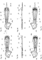
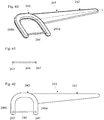
- the invention relates to the field of oral hygiene. It relates to a tooth cleaning device, in particular a finned with a handle body, a connected to the handle body holder with a first and second support arm and with a first and second support arm attached and extending between the two holder arms tooth space cleaning element.
- Flossers are small holders for fixing dental floss for interdental care. In particular, flossing should facilitate the use of dental floss. Flossers are usually offered as a ready-to-use disposable product. Flossers are also known as flossettes or toothed violins.
- the WO 2012 116451 A1 also describes a flosser with a handle and a holder for a dental floss, which are interconnected.
- the holder has two legs, between which the floss is stretched.
- a toothpick is integrated in the handle, which can be angled away by bending over a hinge from the handle body.
- the pre-produced floss is connected to the holder arms of the holder in the manufacturing process.
- the floss is enclosed during an injection molding at its end portions of the holder arms forming plastic compound.
- the finser should be as simple to produce as possible with as little material as possible.
- the Flosser should also be reliable in its application.
- the holder, or its holder arms can be arranged so that the interdental cleaning element extends at a right angle to the handle body. Furthermore, the holder, or its holder arms relative to the handle body also be arranged such that the interdental cleaning element extends at an angle of less than 90 ° and 0 ° or greater relative to the handle body.
- the interdental cleaning element is in particular a longitudinal body, which is insertable into a tooth space.
- the interdental cleaning element connects two holder arms with each other and is in particular stretched between them.
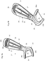
- the holder can form an arc section, via which the holder arms are connected to one another.
- the handle body is connected via the arcuate portion with the holder.
- the holder arms can also lead into the handle body and partially form this.
- the holder arms may include, for example, a gap in the handle body.
- the holder arms can also be connected to each other in the handle body via connecting webs. Furthermore, a connecting web can limit the grip body from the actual holder.
- the Flosser may have a flexible, resilient portion in a transition portion between the holder arms and handle body, which z. B. yields when the interdental cleaning element is performed with too much pressure.
- the transition portion may be formed resiliently.
- the transition section may in particular be a neck section between holder arms and handle body.
- the flexible design of the transition section can be achieved by the material and / or the geometry.
- the transition section may consist of an elastic material or contain this, z. B. a rubber-elastic plastic. Furthermore, the transition section also included a spring element. This can, for example, be integrated into the flosser as an insert by injection molding.
- transition portion relative to the handle body may have a smaller cross-sectional size, or contain constrictions or grooves.
- the transition section may be designed such that it is yielding or elastic in the longitudinal and / or transverse direction of the float. Furthermore, the transition portion may also be resilient with respect to a rotation about the longitudinal axis of the finned.
- the length of the holder arms of the holder may be e.g. 10 to 25 mm, in particular 14 to 20 mm.
- the width of the holder arms may, for. B. 1 to 3 mm, preferably 1.5 to 2.3 mm.
- the depth of the holder arms can z. B. 1.5 to 2.3 mm.
- the holder arms can have a roundish cross-section, for example circular or oval, or a polygonal cross-section, such as, for example, square or rectangular with rounded corners.
- the cross-sectional geometry and the cross-sectional size of the holder arms may be formed constant or change along their longitudinal extent.
- the holder arms can be z toward its free end. B. rejuvenate.
- cross-sectional geometry and / or the cross-sectional size of the two holder arms may be the same or different.
- the holder may be connected via an integrated hinge with the handle body and be bendable or pivotable via the hinge relative to the handle body from a passive position into a functional position.
- the holder and handle body can be arranged in the passive position of the holder in a common plane.
- the holder is swiveled out of the plane into the functional position via the hinge.
- the hinge can be an integrated film hinge.
- a film hinge has advantages in the production. So this is less expensive. Furthermore, the ergonomics in the application is better.
- Other functional elements such as tongue cleaner, polishing element, mirror, interdental brush, stand, stand or toothpick, can also be moved via a film hinge in a different position. The said functional elements can in particular be pivoted or unfolded via the film hinge.
- connecting means as described below, be provided, by means of which the holder can be locked in its passive and / or functional position releasably or permanently on the handle body.
- a first and on the handle body a second connecting means may be arranged on the holder, via which the connection is made on the holder.
- the connecting means are designed in particular for forming a friction and / or positive connection.
- the connecting means can, for. B. be designed for producing a snap or locking connection and corresponding Latching or snap means included. Accordingly, the connection can be realized detachably or permanently.
- the flosser is preferably made of plastic or contains plastic.
- the finsman can z. B. be made in a single or multi-stage injection molding.
- Individual elements of the flosser in particular functional elements, such as tongue cleaners, or its cleaning elements, interdental cleaning elements, polishing elements, mirrors, interdental brush, or toothpicks, may consist of a different material or contain a different material than other elements of the flosser, such as holders, holder arms or handle.
- the basic elements of the fins namely the holder, the holder arms and the handle body are made in more than one injection molding and more than one material.
- the flosser may contain one or more hard components as well as one or more soft components.
- the soft component may, for. B. be a rubber elastic plastic material.
- the Flosser is integrally formed with its functional elements.
- the functional elements as well as any hinges, predetermined breaking points and connecting means of the float can be produced integrally with the flosser in an injection molding process.
- the flosser can be produced in a so-called co-injection process.
- co-injection process at least two material components, eg. As a hard and a soft component, injected through a common or different injection points simultaneously or sequentially in a common horrkavtician.
- the second component can penetrate the first component or envelop it.
- a first material component are injected into the mold cavity, the mold cavity is partially filled with the first material component.
- the injected first material component is then cooled in the mold cavity, wherein at least one flowable core is maintained.
- a second material component is injected into the same mold cavity of the injection molding tool by the same hot-runner nozzle, wherein the tool cavity is further filled or completely filled with the second material component.
- the still flowable core of the previously sprayed into the mold cavity first material component for. B. in the region of the holder arms or the handle body, displaced in the material flow direction, wherein the, in particular on the cavity wall, at least partially solidified first material component at least partially surrounds the inflowing second material component.
- core-back technology also called composite injection molding
- the different materials are sprayed one after the other. After the cavity is filled by a first component, a change in the cavity is generated. The already filled cavity area is opened or expanded to a still unfilled cavity area. The rest of the filling of the component is done by another sprue with a second component. Both the same component and different components can be used.
- a prerequisite for the core-back process is a molding geometry which allows the cavity for the second component to be released by appropriate means and for the two components to adhere to one another.
- interdental cleaning element is not injection molded, then this can also be previously inserted into the mold and cut before ejecting the fins.
- a tooth space cleaning element are inserted into the mold, and then, in particular in a co-injection Vefahren, a first component, in particular a soft material, are injected. In a further step, a second component, in particular a hard material, is injected. Then the flosser is removed from the mold.
- the holder arms may consist of a hard material or contain this.
- the hard material fixes the interdental cleaning element.
- the handle body may consist of a soft material or contain these, for. B. as a layer outside.
- the various material components form during manufacture, for example, a material and / or positive connection. However, it may be provided in certain applications, as explained below, that the material components do not connect to each other.
- a connecting section of a flexible, in particular elastic material component is arranged between the holder and the handle body, so that the holder and the handle body can be moved relative to one another.
- a connecting section of a flexible, in particular elastic material component for example a soft component
- it can also be provided to dimension the hard component more slenderly and / or to cover it with a soft component in order to achieve said elasticity.
- the flosser can be designed so that it can be separated for use in two or more than two parts. This happens, for example, by kinking or tearing of the parts along a predetermined breaking point.
- the predetermined breaking point can be a weakening zone.
- the Flosser can be flat and contain a flat grip body.
- Flat means that the height of the float or the grip body is much smaller than the length and width of the float or grip body.
- the holder can z. B. with its holder arms lie in a plane with the handle body.
- functional elements may also lie in a plane with the handle body, at least in their passive position.
- the finsman can also be designed as a solid.
- Solid means that the width and height of the same lie in a similar range.
- the solid can be designed as a solid body or as a hollow body.
- a trained as a hollow body volume body can have openings through the body wall to the outside.
- Parts of the fins, in particular the handle body, z. B. contain (reinforcing) ribs, which allow to produce a stable, yet lightweight volume body with the least possible cost of materials.
- the finslicer can contain, for example, a plurality of surface segments which can be folded against one another, in particular in the grip body.
- the folding of the elements happens, for example, along the desired bending points, which z. B. form film hinges.
- the elements or the surface segments can be connected to one another on a case-by-case basis via connecting means, as described in connection with the toothpick.
- the connecting means engage in each other, but also in each other movable, for example, be guided.
- the body can be shaped both flat and voluminous.
- Functional elements of a float can be side by side or one above the other z. B. be arranged in the handle body. Certain parts of the functional elements can have several functions.
- elements of the tongue cleaner, z. B. one or more lamellae or one or more knobs, a connecting means for a form and / or frictional connection between a functional element, such as toothpick or interdental brush, and the handle body form.
- the functional element on the tongue cleaner, which z. B. is provided in the handle body, placed.
- the two functional elements are superimposed.
- the connecting elements can be in the range of another functionality, for example in the functionality or on the backside of the said functionality.
- the interdental cleaning element is integrally formed according to an embodiment variant together with the two holder arms of the finned.
- Holder arms and interdental cleaning element are in particular made integral.
- holder arms and interdental cleaning element can be produced integrally in one or more injection molding or Spritzgiess Marinen. In this way, can be dispensed with a supply and process integration of dental floss, which significantly reduces the manufacturing cost and accordingly the manufacturing cost.
- the holder or the holder arms and the interdental cleaning element can be produced in a single injection molding step, wherein holder or Holder arms and interdental cleaning element consist of the same or different materials.
- the holder or the holder arms and the interdental cleaning element can also be produced in two or more injection molding steps, wherein holder or holder arms and interdental cleaning element z. B. consist of different materials.
- the holder or the holder arms and the interdental cleaning element can be produced in a two-stage injection molding process, in particular in a co-injection process described above.
- a first material component can be injected into the mold cavity in a first injection molding step, which forms the holder or the holder arms and the grip body.
- the second material component is injected, which forms the interdental cleaning element. This happens especially before the first material component is completely solidified.
- the second material component in particular flows through the first material component and thus fills still free part of the cavity which forms the interdental cleaning element.
- the two material components can be injected into the mold cavity via a common injection point (co-injection process).
- the injection point can lie in the holder arms.
- the second material component when spraying the second material component, a part of the first material component can be displaced in the holder arm or arms. That is, the second material component, which forms the interdental cleaning element, breaks through in the region of the holder arms.
- the interdental cleaning element is already inserted into the cavity for the first injection molding step.
- a soft component is then introduced into the cavity.
- a hard component is introduced. Appropriate timing in the method is intended to ensure that the interdental cleaning element is anchored in the hard component.
- the finser has a surface made of a soft component for a good grip.
- the holder arms and the interdental cleaning element enter into a material closure with each other.
- the material of the holder arms and the interdental cleaning element can be coordinated with each other for the purpose of forming an optimal material connection, so that the interdental cleaning element is not torn off during use of the holder arm or torn out of it.
- the interdental cleaning element in a first step, can be manufactured.
- the holder or the holder arms and optionally also the handle body is produced by molding the finisher part from the first injection molding step.
- the separately prepared interdental cleaning member may be, for example, a foil, e.g. B. plastic.
- the film may be a two- or multi-component film.
- the film may be or include a PET film.
- the film can be structured and z. B. have a surface topography.
- the separately prepared interdental cleaning member may also be a dental floss. It is possible that the first step is the actual production of a conventionally known dental floss, which z. B. is provided with nodes at the ends.
- the interdental cleaning element in particular a fiber body, together with laterally arranged from the interdental cleaning element connecting elements is produced integrally in an injection molding.
- the flosser with handle body and holder arms is preferably also produced in an injection molding process and in particular in one piece.
- Holder arms and connecting elements contain connection interfaces, which allow the interdental cleaning element by means of a positive and / or frictional connection, for.
- B. a click or snap connection to connect via the connecting elements with the holder arms.
- a material connection such as gluing or welding, as well as a material closure by encapsulation of the interface is also possible.
- the interdental cleaning member may be made of a soft component or a combination of soft and hard component.
- the interdental cleaning element can, for. B. by means of "core-back technology" are produced.
- the interdental cleaning element is at least partially formed as a fiber body.
- the interdental cleaning element can also be formed continuously between the two holder arms as a fiber body.
- the outer diameter of the fiber body can be 0.08 to 0.3 mm, preferably 0.1 mm to 0.25 mm, when it is produced by injection molding.
- the diameter of fiber bodies of conventionally known dental flosses corresponds to the diameter of common dental flosses.
- the cross section of the fiber body can be round, such as circular or oval, or even polygonal, such as rectangular or triangular. Several cross-sectional shapes can be combined to form a cross-section.
- the cross section can be designed both symmetrically and asymmetrically.
- the outer contour of the cross section is preferably closed.
- the cross-section can change over the length of the fiber body and form a cross-sectional profile.
- the cross section may be larger at the ends than in the middle section.
- the cross-section may also have a wavy increasing and decreasing cross-sectional profile over the length.
- a different cross-sectional profiling brings with it a correspondingly variable longitudinal profiling, which in turn can be wave-shaped, rectilinear or else cross-section-dependent.
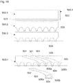
- the interdental cleaning element can contain radially projecting cleaning elements, such as bristles, nubs or lamellae, from a central base body or fiber body.
- the cleaning elements can, for. B. annular, over the full circumference, ie 360 ° (degrees) or over one or more sub-circumferences of the body can be arranged.
- the lamellae can surround the base body as a lamellar ring or spirally.
- the interdental cleaning element or its central body can be equipped with a special surface.
- the surface can be embodied, for example, as a texture such as corrugation, erosion structure, alternately smooth / polished surface, roughened surface or else in a combination of the abovementioned possibilities.
- the exit point of the interdental cleaning element from the holder arms is a key point.
- This transition is preferably not sharp-edged and provided with generous transition radii. Furthermore, a funnel-shaped constriction is possible away from the holder arms.
- the cleaning elements may be arranged in sections or over the entire longitudinal extent of the interdental cleaning element between the two holder arms. It can also be provided between the two holder arms sections cleaning elements and sections a fiber body be. For example, cleaning elements may be provided only in a central region of the interdental cleaning element.
- the cleaning elements may be formed integrally with the main body or fiber body.
- holder arms, cleaning elements and base body can be integrally manufactured in an injection molding process.
- the interdental cleaning element may also be formed as a separate component, which in the manufacturing process, for. B. by injection molding, or a mechanical assembly step is connected to the holder arms.
- the interdental cleaning element may also be a fiber body in the form of a toothed thread, which consists of one or a plurality of fibers, for. B. consists of plastic fibers.
- Such interdental cleaning elements for interdental cleaning are also known as dental floss.
- the fiber body can be integrated with its end portions in an injection molding in the holder arms.
- anchoring elements which are, for example, spherical or cylindrical, may be provided in the end sections of the dental floss.
- the anchoring elements can be injection-molded onto the fiber body in an injection molding process.
- the anchoring elements can also be in the fiber body, in particular in the floss, introduced nodes.
- connecting elements laterally to the interdental cleaning element, for. B. to a fiber body, such as dental floss, are attached.
- These can be z. B. be injection molded in an injection molding.
- the connecting elements and the holder arms of the float have connection interfaces for producing a positive and / or non-positive connection or material connection on.
- the interdental cleaning element can now be connected to the holder arms in a mechanical assembly step via the connecting elements by means of a positive and / or non-positive connection or fabric connection.
- the interdental cleaning element in particular the fiber body, may be biased or unstressed between the holder arms. Regardless of the type of fibrous body, e.g. When designing (shaping) the fins, make sure that the holder arms exert a (tensile) tension on the fiber body after the plastic material has solidified and the resulting shrinkage has occurred.
- connection points between the holder arms and the interdental cleaning element are preferably arranged at the outermost end of the holder arm.
- the interdental cleaning member and the end points of the holder arms may preferably lie in line, particularly in the case where the interdental cleaning member is injection-molded.
- the holder arms do not form end portions extending beyond the interdental cleaning element.
- a distance may also be formed between the outermost end or between the free end of the holder arm and the connection point.
- connection point to the holder arm is preferably on the median plane passing through the holder arms.
- tooth space cleaning elements in particular fiber bodies, arranged at a distance from one another can be provided.
- the interdental cleaning elements each form along the holder arms spaced connection points to the holder arms.
- the interdental cleaning elements can be arranged parallel to each other.
- the interdental cleaning elements can be arranged crossing each other.
- the interdental cleaning elements may be arranged at an angle to each other.
- the distance between the interdental cleaning elements or between their connection points can be 0.5 to 3 mm, preferably 1 to 2 mm.
- the plurality of interdental cleaning members may be arranged in a line along the holder arms.
- the plurality of interdental cleaning elements may be arranged in a plane.
- the interdental cleaning elements in particular when three or more of them are provided, can be arranged laterally offset from one another and consequently not in a common plane, viewed transversely to the holder arms. Accordingly, the connection points on the holder arm are not in line.
- the interdental cleaning elements may be the same or different.
- a first, outer interdental cleaning element may be formed as a film of a PTFE and a second, inner interdental cleaning element as a bulk dental floss.
- the first interdental cleaning element facilitates facilitated penetration into the interdental space. Both interdental cleaning elements together serve to clean the interdental space.
- the tooth space cleaning element produced by injection molding may consist of hard and / or soft material or of a mixture of hard and soft material. Furthermore, a use of material is possible, which is used for the production of sprayed bristles.
- the distance between the holder arms or the length of the interdental cleaning element is between 10 and 25 mm, preferably between 12 and 18 mm.
- the holder contains at least one damping element. This may be of particular importance when the holder and in particular the holder arms are made of a hard component. As explained below, the damping element serves to reduce impacts on gums and teeth by the finser during its use.
- the damping element preferably has elastic properties.
- the elastic properties may be due to the material and / or by the shaping.
- the damping element may consist of a soft component or contain these. This is especially true when the elastic properties of the damping element are due to the material.
- the damping element may be formed as a solid body, in particular if the elastic properties are caused by the material.
- the damping element may consist of or contain a hard component. This is especially true when the elastic properties of the damping element are due to the shaping.
- Elastic properties through the shaping are achieved, for example, by an embodiment of the damping element as a hollow body, or by a concertina-like configuration.
- a hollow body contains, for example, elastic walls.
- the damping element can also be designed as an elongate element of comparatively small diameter.
- the damping element can, for. B. be designed as a bow.
- the damping element can be shaped as a self-contained, semi-open or open geometry.
- the damping element may be formed integrally with the arms or the bow portion. Damping element and arms or arc section can be made integrally in an injection molding process. The production of the float with damping element can, for. B. done in a multi-component injection molding.
- the damping element can be injection-molded onto the holder, for example in a multi-stage injection molding process in a separate injection molding step.
- a damping element is arranged between the two arms and in the direction of the grip body at a distance from the interdental cleaning element.
- the damping element points with its damping portion to the interdental cleaning element.
- the damping element can be arranged in particular in the arc section, which connects the holder arms together or form this arc section.
- the damping element serves as protection against injury by the made of a hard component elements of the fins in the jerky penetration of the interdental cleaning element in the interdental space or as protection for deep penetration of the interdental cleaning element in the interdental space respectively. in the gums.
- the damping element can be used for tooth space cleaning element z.
- the damping element may also be formed as an elastically deformable arc, which is arranged in the arc section and extending between the holder arms.
- the bow can z. B. be designed flat.
- the damping material may also consist of a hard component.
- the bow is preferably convex. It is also possible that the damping element is wave-shaped, perforated, lamellar, etc. is formed.
- the damping element can also be arranged on a connecting web connecting the arms with one another in the transition to the handle body or form this.
- the damping element is arranged on the inside and / or outside of the holder arm.
- the damping element can be from the arc section to the connection points of the interdental cleaning element extend to the holder arms.
- On the inside means that the damping element is directed to the interdental cleaning element.
- the damping element dampens in particular impacts of the flosser against the teeth and gums, as they can occur when the float is moved back and forth.
- the interdental cleaning element preferably leads through the damping element at its point of connection to the holder arm.
- the damping element is arranged around the junction of the interdental cleaning element.
- the interdental cleaning element can also be connected to the damping element, in particular it can be integrally connected.
- the diameter of the damping element can, for. B. 1 to 6 mm, preferably 2 to 4 mm.
- the diameter preferably decreases starting from the holder arm in the direction of the opposite holder arm.
- the length of the damping element in the direction of the interdental cleaning element is, for example. 1 to 4 mm, preferably 2 to 3 mm.
- the damping element may be arranged, for example rotationally symmetrical about the interdental cleaning element.
- the damping element may also have a shape adapted to the tooth geometry.
- the damping element may be formed as a hollow body or as a solid body, in particular a concertina-like shape is possible.
- the damping element may be fixed to the respective holder arm, for example molded, glued or mechanically latched. Furthermore, the damping element also loose, that can be arranged to be movable in the longitudinal direction of the interdental cleaning element.
- the damping element is arranged on the end portion of the holder arms.
- the damping element can, for. B. can be arranged like a cap over the end portion.
- the end portion may be coated with a soft component.
- the length of the coating in the direction of the holder arms may, for. B. 1 to 5 mm, preferably 1 to 3.5 mm.
- the layer thickness can z. B. 0.1 to 1.5 mm, in particular 0.3 to 1 mm.
- the damping element is arcuate along the inner arc formed by the arcuate portion and the holder arms, i. arranged along the bow portion and the holder arms.
- the damping element may further extend around the end portions of the holder arms to the outside thereof and cover the end surfaces of the holder arms.
- the damping element is designed in particular as a kind of lip.
- the damping element is fastened on the arc section and the holder arms, in particular fastened continuously.
- the damping element along the inner arc is formed as an exposed, lip-like element.
- the damping element z. B. only with its end portions on the outside of the holder arms in the region of their end portions to be attached to this.
- damping element z. B. is fixed selectively or in sections on the inner bow and is formed sections lying freely.
- Damping elements according to the first, second, third, fourth and fifth aspects can be combined with one another as desired.
- the flosser may further include a tensioning element for tensioning the interdental cleaning element, in particular the fiber body.
- the tensioning element may be a finger rest on one of the holder arms. The clamping of the interdental cleaning element takes place by applying pressure to the finger rest by a finger.
- the holder arm which is used for clamping, preferably contains an elastic zone so that it is elastically bendable for tensioning the interdental cleaning element. This can be z. B. a taper in the holder arm or an arm portion of one or with a soft component.
- the clamping element is preferably arranged on the holder arm, which is arranged on the handle body side.
- the finser in the handle body contains at least one or more further functional elements for oral hygiene.
- the one or more other functional elements are preferably integrally formed with the handle body.
- the one or more other functional elements are produced with the handle body in particular integrally in an injection molding process. Accordingly, it may consist of the same material component as the handle.
- the further functional element can with respect to the handle body of another material component, such. B. soft component, exist or contain.
- the functional element is made of the same material component as the handle body, but is introduced in a separate injection molding step. In this way, for example, a different color can be realized, or other additives of the material component can be mixed.
- the further functional element can be bent away from the handle body via an integrated between the handle body and the functional element hinge and angled from this. Furthermore, it is also possible for the hinge to be arranged in the grip body and for a part of the grip body to be pivoted away via the hinge, as a result of which the functional element is exposed from the grip body.
- the hinge may be, for example, a living hinge.
- the swivel angle can be arbitrary and is determined by the geometric conditions.
- the swivel angle may in particular also include 30, 60, 90, 120, 150 and 180 degrees.
- the further functional element may include a first connecting means.
- a second connecting means is preferably arranged on the handle body.
- the connecting means are designed to form a releasable or non-detachable connection between the functional element and the handle body in the swung-out state of the functional element, when this is in the functional position.
- connecting means is disclosed, for example, below in connection with the toothpick.
- the connecting means are applicable to various functional elements such as toothpick, tongue cleaner, polishing element, mirror, interdental brush etc.
- a hinge may also be provided a predetermined breaking point, via which the functional element can be broken away from the handle body and used as a separated part.
- a connecting element can be provided on the grip body, which allows the functional element which has been broken off by the grip body to be mounted or fastened thereto again. This can be done for example via a positive connection, such as latching connection.
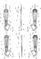
- the further functional element may be, for example, a toothpick.
- the toothpick can be fixedly attached to the finned or, as already described, be foldable out of the finner or be detachable from the finslicer.
- the toothpick has a cleaning tip at its free end.
- the Flosser may include a cap to cover the cleaning tip or the toothpick.
- the cap can be plugged onto the toothpick or the cleaning tip.
- the cap can be made by injection molding.
- the cap may be made of a different plastic material than the toothpick.
- the cover may in particular be made of a material that does not connect to the material of the toothpick.
- the production of the cap can thus be done in the same injection molding as the toothpick.
- the cap itself may form a functional element.
- This functional element may be a brush, such as a twisted brush or a small toothbrush.
- the toothpick serves as a basic structure for the functional element.
- the toothpick is in particular not pivotally mounted according to this embodiment variant.
- the cross-sectional shape of the toothpick may be round, such as circular or oval, or polygonal, such as rectangular or triangular.
- the toothpick may be formed flat, with two opposing surface sides and two opposite narrow side edges.
- the cross section of the toothpick may be decreasing from the exit point to the cleaning tip and running into a point.
- the cross section can be formed consistently over the length and taper in an end portion to a point.
- the surface of the toothpick may be smooth or rough.
- the surface may contain a texture and z. B. be corrugated or another roughness pattern, such as erosion structure included.
- the toothpick may also contain protruding elements, for example in the form of geometric figures such as crosses or lines.
- the toothpick can be rectilinear or curved, z. B. sickle-shaped.
- Straight line means that the cleaning tip lies in the longitudinal axis of the toothpick.
- the toothpick can be pivoted away from a pivoting position between a handle body and toothpick hinge from a passive position into a functional position of the handle body and in particular from its plane and angled from this.
- a hinge may also be provided a predetermined breaking point, over which the toothpick can be broken away from the handle body.
- the toothpick may be in the passive position in the plane of the handle body.
- the toothpick or generally the functional elements can be pivoted in different directions.
- the toothpick may be placed over the interdental cleaning member or on the opposite side of the interdental cleaning member.
- the toothpick preferably forms side edges which converge towards one another in a point. Further, the toothpick may form an upper and lower base between the side edges.
- the base surfaces of the toothpick are arranged, for example, parallel to the plane of the handle body.
- At least the tip of the toothpick and preferably the whole toothpick in the passive position along the side edges at least partially, preferably completely surrounded by the handle body.
- the handle body or parts thereof form a protection for the toothpick, in particular for the cleaning tip from.
- the toothpick and in particular the tip of the toothpick is in the swung-out state, i. in the functional position, preferably pivoted away from the plane of the handle body and stands in particular from this.
- the cleaning tip of the toothpick points away from the grip body.
- the toothpick can still lie in the functional position in the plane of the handle body or form an angle to this.
- the handle body may form, for example, a gap.
- the handle body may include first and second arms that enclose the gap.
- the arms are connected together in the end portion of the handle body remote from the holder.
- the arms can also be the continuation of the holder arms.
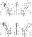
- the toothpick can be arranged in its passive position and connected via the hinge or the predetermined breaking point with the handle body.
- the hinge or the predetermined breaking point may be arranged at the end portion of the handle body, which is remote from the holder, or on one of the arms or on a connecting web between the two arms.
- the connecting web can be arranged, for example, towards the holder.
- the toothpick may also be arranged laterally on the grip body, so that one side edge of the toothpick is directed toward the grip body and the other side edge of the toothpick forms a section of the outer contour of the grip body.
- a second connecting means may be arranged at the toothpick.
- the connecting means are designed to form a releasable or non-releasable connection between the toothpick and the handle body in the swung-out state of the toothpick when it is in the functional position. By the connection described the toothpick is kept in functional position.
- the connecting means are designed in particular for forming a friction and / or positive connection.
- the connecting means can, for. B. be designed for producing a snap or locking connection and contain corresponding locking or snap means.
- one connecting means may comprise a recess or aperture, such as a blind or through hole, and the other connecting means may be an increase, e.g. B. contain a knob or pin.
- the toothpick is pivoted out, the elevation reaches positively when the functional position is reached in the depression or in the breakthrough.
- the connection is z. B. made by a click effect.
- the toothpick can also be broken away from the handle body via a predetermined breaking point and reassembled with the handle body via the said connection means in the functional position.
- Nub and depression or breakthrough can be cylindrical.
- the nub may have a rounded end.
- the nub may also be designed as a hemisphere.
- the nub may be conical. That is, the diameter at the free end is smaller than the diameter at the neck.
- the nub may also be conical only to the end portion.
- the height of the conical end portion is z. B. maximum 50% of the total height.
- the depression or breakthrough may have a diameter of 0.5 to 2 mm, preferably 0.8 to 1.5 mm.
- the nub may have a diameter of 0.5 to 2 mm, preferably from 0.8 to 1.5 mm.
- the nub may have a height of 0.8 to 3 mm, preferably 1.2 to 1.8 mm.
- recess and nub preferably passes through a clamping or detent.
- the clamping is generated by an excess, which means that the two elements "overlap".
- the overlap is from 0.005 to 0.2 mm, preferably from 0.01 to 0.06 mm.
- a detent can be achieved by geometric undercuts and corresponding protrusions on the counter element.
- the hinge or the predetermined breaking point is arranged in the grip body and one or more parts of the grip body, below guard parts, can be swung away or broken away via the hinge or the predetermined fractions, whereby the toothpick is exposed.
- the named protections protect the toothpick in its passive position.
- the protection can be fixed in the functional position by one or more connecting means, but it can also be equipped without fixing. The same applies to the toothpick which is bent into the functional position.
- the protective parts themselves may contain a functional element, such as tongue cleaners.
- the handle body may be at least partially formed at least two layers.
- the one layer forms a functional element such as a toothpick, which can be swung in the described manner via a hinge from the handle body or can be broken away from the handle body via a predetermined breaking point.
- a protective cap Over the toothpick, in particular over the cleaning tip, a protective cap can be arranged, which is removable for use.
- the protective cap is preferably placed over a form and / or frictional connection.
- the protective cap may be made of a soft component with, for example, elastic properties, which clamps on the toothpick.
- the protective cap can also be made of a hard component.
- the protective cap is preferably sprayed in a multi-component injection molding process, wherein the plastics of the protective cap and the toothpick or its surface are preferably not connecting.
- the toothpick can be further provided with a soft surface, the core is made of hard material and the surface of soft material. Hard and soft materials have a material shortage in this case.
- the various zones (toothpick, tongue cleaner, damping element, gripping surfaces, bristle body, polishing body, etc.) made of soft material on the fins in the same manufacturing step by means of an injection point created.
- the Flosser can contain a tongue cleaner as another functional element.
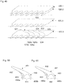
- the tongue cleaner may, for example, contain one or more identical or differently designed cleaning elements.
- the tongue cleaner or its cleaning elements can be arranged in the grip body, in particular in its end portion which is remote from the holder.
- the receiving element can, for. B. be a spring arm, which brings in use a certain elasticity with it.
- the elasticity can be realized in this case, for example, by bodies on the spring arms, which are realized as material weakenings.
- the receiving element can, for. B. on a hinge, in particular film hinge, from the handle body of a passive position in a functional position be pivotable.
- the receiving element may also be break-away from the handle body via a predetermined breaking point.
- the spring arms are preferably U-shaped contours that are closed. A realization of spring arms that are not closed, is possible, but such a configuration for oral hygiene is not optimal due to the injury potential sting by.
- the said spring arms make it possible, for example, to realize different cleaning elements on different spring arms and thus to realize a tong spring constructed with tongue arms.
- Such a structure would be possible, for example, by a plurality of U-shaped spring arms which lie in one another.
- the cross section of the individual spring arm can vary over the length, for example, from the spring arm profile to the doctor edge profile.
- the tongue cleaner or its cleaning element can also be arranged on the holder or on its holder arms, on the curved portion, on the toothpick or on another functional element.
- the tongue cleaner or its protruding cleaning elements may be arranged on the outside of the holder arm.
- the cleaning elements can z. B. be arranged in a row next to each other on the holder arm.
- the tongue cleaning takes place in a direction of movement transverse to the longitudinal direction of the fins.
- the cleaning elements can be arranged and aligned so that the cleaning movement can be performed transversely to the longitudinal axis of the handle body or in the longitudinal axis of the handle body.
- the cleaning element may, for. B. be a lamella.
- the lamella can z. B. in the longitudinal axis of the handle body, be arranged transversely thereto or at an angle to the longitudinal axis.
- the lamella may comprise an end edge.
- the slat is z. B. flexible, ie designed compliant.
- the lamella can in particular elastic Have properties.
- the blade or the spring arm described above can be made of a soft component or a combination of soft and hard component.
- the lamella may have a width of 0.25 to 1.2 mm, preferably of 0.6 to 0.9 mm.
- the lamella can have a height of 0.4 to 3 mm, preferably 1 to 2 mm.
- the lamella can have a length of 0.5 to 2.5 cm, preferably 1.5 to 2 cm.
- the tongue cleaner may contain several slats, which z. B. are arranged one behind the other in series. Furthermore, the lamellae can also form a lamellar field. The lamellae may be of the same or different geometry and / or material. This allows soft and hard blades to alternate.
- a single lamella offset from the rest of the reed cleaner is also referred to as the doctoring edge.
- Scraper edges are made of hard material or a combination of hard material and soft material, preferably hard material.
- the cleaning element may also be a nub.
- the knob is a hump-like, conical or spherical elevation on a surface to understand.
- the knob is z. B. flexible, ie designed compliant.
- the nub may in particular have elastic properties.
- the nub may be made of a soft component, a hard component or a combination of soft and hard component.
- the knob can z.
- the nub may have a diameter of 0.25 to 1.2 mm, preferably from 0.6 to 0.9 mm.
- the nub may have a height of 0.25 to 0.6 mm, preferably 0.3 to 0.45 mm.
- the tongue cleaner may contain several nubs, which z. B. are arranged one behind the other in a row or side by side in a row. Furthermore, the nubs can also form a nubble field.
- Knobs and / or fins and / or scraper edges can be produced integrally with the fins or with the handle body in an injection molding process, in particular in a multi-component injection molding process.
- the cleaning element may also comprise a bristle body.
- the bristle body contains a plurality of bristles.
- the bristles may be injection molded integrally with the finser, i. be injected.
- the diameter of a single bristle is z. B. 0.25 to 1.2 mm, preferably 0.6 to 0.9 mm.
- the length of a single bristle is z. B. 1.5 to 4 mm, preferably 2 to 3 mm.
- the bristle may also be formed as a hollow body.
- the cross-sectional contour should be injection-moldable.
- the single bristle may include an end cap. This can be square or round.
- the bristle body may contain individual rows of bristles.
- the bristle body may also contain a bristle field.
- cleaning elements such as lamellae, bristle bodies and nubs are also possible. This allows nubs and lamellae to alternate. Furthermore, lamellae and bristle bodies can alternate.
- the Flosser may contain a polishing element as another functional element.
- the polishing element is used to polish the tooth surfaces, e.g. to get rid of deposits.
- the polishing surface preferably consists of a soft component.
- the polishing element may be a solid z. B. from a soft component.
- the polishing element may also have a base body, for. B. from a hard component, and applied to the body polishing piece, z. B. from a soft component. Further, it is possible to design the polishing element as a spherically shaped membrane of a soft component, wherein the membrane is fixed to a frame made of a hard component.
- the soft component preferably has elastic properties.
- the polishing part may also be formed as a membrane of a soft component, wherein the membrane is fixed to a frame made of a hard component which forms part of the base body.
- the membrane is preferably elastic.
- the polishing element may be disposed in the end portion of the handle body which is remote from the holder.
- the polishing element may form a polishing surface which is raised relative to the handle body.
- the polishing element may be formed, for example, hump-like.
- the polishing element may have a diameter of 3 to 15 mm, preferably 4 to 8 mm.
- the polishing element may have a height of 1 to 5 mm, preferably 2 to 3 mm.
- a polishing member formed as a membrane may have a thickness of 0.3 to 1.2 mm, preferably 0.5 to 0.8 mm.
- the finsman may contain a mirror as another functional element. Like the toothpick, the mirror can be folded out via a hinge or separated from the fins via a predetermined breaking point. For this purpose, reference is made to the relevant disclosure.
- the mirror can be integrated into the flosser as an insert by injection molding.
- the finslicer can contain as a further functional element a small toothbrush, in particular a disposable toothbrush, with a bristle field.
- the bristles are injected in particular by injection molding.
- the Klein leopardbürste can be hinged over a hinge, such as film hinge.
- the Klein leopardbürste can, for. B. via a predetermined breaking point, be separated from the fins.
- the Flosser can contain as an additional functional element an interdental brush.
- the interdental brush can be attached to the handle body and, for example, analogously to the toothpick, be pivotable or foldable via a hinge from a passive position into a functional position out of the handle body.
- the interdental brush can also be break-away from the handle body via a predetermined breaking point.
- the handle body or parts thereof can form a protection for the interdental brush in the passive position analogous to the toothpick.
- the interdental brush can also be integrated into the interdental cleaning element arranged between the holder arms and held by them.
- the interdental cleaning element as described above contains bristles.
- the interdental brush contains a plurality of bristles.
- the bristles or the interdental brush can be sprayed in an injection molding process and be an integral part of the fins.
- the interdental brush can also be arranged as a so-called single tuft and attached by a Beborstungsvon (tufting) on the flosser.
- the interdental brush can also be a screwed-in brush.
- the interdental brush can be a basic body, such.
- the bristles can be aligned in the plane of the base body.
- the Flosser may contain a suction cup as another functional element.
- the suction cup may be attached to the handle body.
- the suction cup is used to attach the fins on a surface. So the finslucker can be hung on a bathroom mirror by means of a suction cup or placed safely on a surface.
- the finslicer can contain as a further functional element a foot or a support element for supporting the fins on a surface.
- the foot or the support element may be attached to the handle body.
- the foot can be folded out, z. B about a movie hinge.
- the foot can also be separated from the fins, z. B. over a predetermined breaking point, and to exercise its function via a positive connection, z. B. connector, be attached to the fins.
- the support element may, for. B. be designed as a stand.
- the stand can z. B. be rattling.
- the stand can z. B. form a tripod with the fins.
- the stand can be folded over a film hinge analogous to the toothpick. Reference is made to the description.
- the foot or the support allows you to set up the flosser to dry.
- the suction cup or the foot or a support element can be produced integrally in an injection molding process, in particular in a multi-component injection molding process, together with the finisher or the handle body.
- the flosser may contain one or more functional elements for dispensing at least one active substance.
- the at least one active substance forms z. B. together with a suitable carrier material, the functional element.
- the functional element can be, for example, an active body, in particular a sphere (bead).
- the active body can be a solid.
- the Wirkkugel can z. As a mouthwash or a tooth cleaning substance.
- the active substance may, in particular together with a carrier material, be in granular, powdery, liquid, pasty or gelatinous form.
- the active substance of the functional element may, for example, be water-soluble.
- the active substance may be used for cleaning, disinfecting, flavoring and / or perfuming in connection with oral hygiene. Furthermore, the active substance can serve to indicate a cleaning success. Furthermore, the active substance can also be used for bleaching the teeth (bleaching).
- the cleaning substance in cooperation with conventional cleaning agents, in particular toothpastes, act as a two-component system.
- active substances When the active substances come together, a chemical or physical reaction occurs.
- This system is particularly intended for active substances, which can not be integrated together into a cleaning agent, such as toothpaste, as otherwise they would react directly with one another.
- the functional element may contain one or more different active substances.
- the functional element may contain a plurality of active substances which are released successively in the course of time and thus develop different phases of action.
- the functional element may be an active body in the form of a solid, which comprises a plurality of shells or layers, each with different active substances, wherein over time a shell or layer is degraded after the other.
- the active body may contain a shell and a liquid or powdery or granular core, which is released after degradation of the shell.
- the functional element is arranged with its delivery area for active substances, in particular in the vicinity of cleaning elements, such as bristles and / or soft elastic elements, which cause the active substances to develop their optimal effect in cooperation with mechanical movements of the cleaning element.
- cleaning elements such as bristles and / or soft elastic elements
- cleaning elements can be designed so that the functional element for active substances is part of the cleaning element.
- the active body is z. B. attached to the fins.
- the active body can, for. B. in a recess in the fins, z. B. be arranged in a recess in the holder arm.
- the functional element in particular active body, can be arranged directly on a tongue cleaner, on a polishing element, on a toothpick, on an interdental brush, on a small toothbrush, on the holder arms, on the tooth space cleaning element, on the damping element or on the grip body.
- the small toothbrush may contain a body of action, in particular a sphere (bead), with a detergent active substance.
- the active substance z. B. have an antibacterial effect in the brush head of an interdental brush or a Kleinfahnbürste.
- the functional element can also be used as a coating, for. B. by spraying, dipping, brushing, steaming, etc. be appropriate.
- the functional element can be mounted in an injection molding process.
- the functional element can also by gluing, z. B. as a label, be appropriate.
- the functional element can also be mounted or mounted in a Deutschenfangung.
- the functional element can also be attached by a form-locking connection, such as a riveted connection
- Active material-containing materials often go with other plastics no material connection, so that in these cases a mechanical connection is necessary in particular by positive locking.
- the active substance may be, for example, a mouthwash, toothpaste or a tooth cleaning extract.
- the functional element with active substance may be attached to a tongue cleaner or a polishing element, on one of the cleaning or polishing effective side opposite side.
- the finslicer can contain a sensor element as a further functional element.
- the sensor element may be attached to the handle body.
- the sensor element may be designed to detect certain parameters, such as bad breath, pH or bacteria.
- the sensor element can be attached as a sensor strip on the fins.
- the grip body can form special grip surfaces, in particular grip recesses. These are characterized by a special structuring or texture of the surface (roughness pattern) and / or by a special choice of material (adhesive properties).
- the gripping surface may contain grooves, lamellas or nubs.
- logos / logo submerged or submerged in the body can be incorporated, which of course also serve the better grip.
- the material may have good adhesive properties.
- adhesive properties are z. B. with the use of a soft component or a achieved rubbery material.
- the grip body may contain a thumb grip.
- the surface of the thumb grip, ie the gripping surfaces can be formed as described above and z. B. from a soft component or contain these.
- the cleaning elements such as knobs and fins, grip surfaces for the fingers, especially the thumb form.
- the tongue cleaner can also serve as a thumb grip.
- the handle body may also have for the purpose of saving material and weight optimization breakthroughs and depressions.
- the flosser may further include means for tensioning the interdental cleaning member. These means, which are described below with reference to two embodiments, can be implemented on any fins.
- the interdental cleaning element in particular a dental floss, often loses a prestress introduced before and during the injection molding step.
- the means for clamping should now counteract in particular the loss of the bias by the material shrinkage.
- At least one holder arm or both holder arms contain at least two different materials, in particular plastic materials.
- the at least two materials are characterized in particular by a different shrinkage behavior during cooling. As a result, a bimetallic principle similar effect is achieved.
- the materials are now arranged in the at least one holder arm such that upon cooling of the finisher following the injection molding process, the bias of the interdental cleaning element during cooling is maintained or less pronounced, or the tension is even increased.
- the at least one holder arm is constructed, for example, in a multi-layered manner transversely to its longitudinal direction.
- a plastic material may be arranged with a higher shrinkage and on the inside of the holder arm, a plastic material with a lower shrinkage compared between the two plastic materials.
- the at least one support arm can be bent during cooling, in particular outwards, and thus tension the interdental cleaning element.
- the at least two plastic components in the holder arm can be connected to one another via a fabric or positive connection.
- the finser contains a tension element.
- the tension element can, for. B. a rib or web, in particular connecting rib or connecting web, be.
- the tension element is in particular connected to a holder arm.
- the tension element can be designed and arranged on the finser such that it exerts a tension on the holder arm acting on the outside, away from the interdental cleaning element, upon cooling by the fading. This tension causes the bias of the interdental cleaning element during the cooling is maintained or less pronounced degraded, or the voltage is even increased.
- the tension member may even cause it to flex the holder arm outwardly away from the interdental cleaning member during cooling, thus increasing the tension of the interdental cleaning member.
- the tension element is mounted in particular on the outside of the holder arm.
- the tension element in particular connects the outside of the holder arm with the handle body or a neck portion.
- the tension element spans a bend or arc formed by the holder arm and the grip body.
- the tension element can be arranged on the inner holder arm of an angled formed finned, facing the handle body.
- the tension element is in particular likewise made of plastic and is produced by means of injection molding.
- the tension element is in particular produced together with the finser in an injection molding process.
- the pulling element may be made of the same plastic as the holder arm or the handle body.
- Another embodiment of a float is characterized by the special nature of its manufacture.
- a sheet-like component made of plastic or plastic is produced.
- the planar component may be plate-like.
- the planar component is in particular a two-dimensional extrusion profile made of plastic.
- the component is formed in particular band-shaped.
- the component is in particular a longitudinal component.
- the component contains in particular a longitudinal groove. This can be subsequently introduced into the component.
- the longitudinal groove may also be coextruded in the extrusion profile.
- recesses are introduced into the component side by side and at a distance from each other on the one longitudinal side of the component, which recesses are open towards the longitudinal side.
- the recesses can z. B. be introduced by punching.
- the recesses are in particular arcuate.
- the recesses are each identical in particular.
- finger-shaped projections Between two recesses arise finger-shaped projections. These form the later holder arms.
- the recesses form between the finger-shaped projections a gap, which is spanned by the later introduced interdental cleaning element.
- the longitudinal groove is arranged after this step in the form of L Lucassnutabroughen in the finger-shaped projections.
- the longitudinal groove is no longer continuous but interrupted.
- the interdental cleaning element in particular a fiber body or tooth filament, is inserted into the longitudinal groove sections in the finger-shaped projections and locked in this.
- the locking can be done by latching, clamping, gluing, welding or pressing.
- a film hinge may be provided, to which a pivoting section adjoins the longitudinal side.
- the pivoting portion forms in particular a later end portion of the finger-shaped projection.
- the interdental cleaning element is now inserted in the region of the pivot portion and clamped by pivoting the pivot portion.
- the interdental cleaning element can alternatively also be welded or glued.
- a fourth step individual fins are separated along a predetermined parting line from the prepared component, z. B. by punching.
- the dividing line leads through the finger-shaped projections and subdivides these into a respective holder arm of two adjacent fins.
- the severed finisher includes a pair of holder arms, a tooth space cleaning member extending therebetween, and a handle body.
- the present embodiment is characterized by a favorable and extremely efficient manufacturing process, which is ideal for mass production.
- the fins produced in this way have an optimal tension of the interdental cleaning element, since in comparison to injection molding, the bias voltage is not reduced by fading effects, this is because the processing of the extruded component is preferably carried out in the cold state.
- Another embodiment of a float is also characterized by the special nature of its manufacture.
- two flat components made of plastic, or containing plastic are produced.
- the components may be foils or plates.
- the components may be extrusion components.
- recesses are introduced into the components on one longitudinal side of the two flat components side by side and at a distance from one another, which are open towards the longitudinal side.
- the recesses can z. B. be introduced by punching.
- the recesses are z. B. arcuate.
- the recesses are each identical in particular.
- finger-shaped projections Between each two arcuate recesses arise finger-shaped projections. These form the later holder arms. The recesses form between the finger-shaped projections a gap, which is spanned by the later introduced interdental cleaning element.
- a third step the two components are brought together and connected areally.
- the recesses or finger-shaped projections in the two components are aligned with each other, i. in register.
- the tooth space cleaning element is inserted in the region of the end portions of the finger-shaped projections between the two components and connected to the two components.
- the connection of the two components and according to the attachment of the interdental cleaning element can be done by gluing or welding.
- connection of the two components can either over the entire area, i. over the entire identical area of the components, or only partially, i. over part of the total identical area.
- a fourth step individual fins are separated along a predetermined parting line from the prepared component, z. B. by punching.
- the dividing line leads through the finger-shaped Anformung and subdivided into a respective holder arm of two adjacent fins.
- the separate flosser contains two holder arms, a toothed thread running between them and a handle body.
- a three-dimensional structure with elevations and depressions in the component, by a deep-drawing process or an embossing process, especially in the later handle body of the finned be introduced.
- the three-dimensional structures can improve the feel and increase the stability of the float.
- the three-dimensional structures may be incorporated into one or both of the components prior to joining the components.
- the three-dimensional structures can also be introduced into one or both of the components after the connection.
- the introduction of three-dimensional structures in the area of the thread holder can serve to improve the thread holder.
- haptic labels on the surface, which give the surface more structure and thus improve the ergonomics and the grip.
- the present embodiment is characterized by a favorable and extremely efficient manufacturing process, which is ideal for mass production.
- the fins produced in this way have an optimal tension of the interdental cleaning element, since in this case the pre-stress is not reduced by shrinkage effects compared to injection molding.
- Another aftertreatment option relates to the interdental cleaning element. Certain properties that the interdental cleaning element should have can have negative effects on the manufacturing process. Therefore, it is possible to provide the interdental cleaning element only in a post-treatment with these properties. Possibilities here are in particular the subsequent application of substances for changing the sliding properties or of flavorings or active ingredients.
- the interdental cleaning element may be made of polyamide (PA), in particular PA6, PA6.6, PA6.10, PA6.12, polytetrafluoroethylene (PTFE), polyethylene (PE) or polyester.
- PA polyamide
- PTFE polytetrafluoroethylene
- PE polyethylene
- the interdental cleaning element may be coated or uncoated.
- the interdental cleaning element may be waxed or unwaxed. Examples of waxes are beeswax (Cera Alba), Cera Microcristallina or Vinapas® from Wacker Chemie AG.
- the interdental cleaning element can also be impregnated or have a further coating.
- the impregnation or coating can serve to spread the taste (eg mint).
- the impregnation or coating may also include an active ingredient, such as fluoride (sodium fluoride or ammonium fluoride) or chlorhexidine.
- the finisher may have an overall length of 6 to 11 cm, preferably 7 to 9 cm.
- the flosser may have a total width of 2 to 4 cm, preferably 2.5 to 3.5 cm.
- the flosser may have a height of 1 to 3 mm, preferably 1.5 to 2.3 mm.
- the information on height concerns only the handle body but not the functional elements arranged thereon, whose mass may differ.
- the height to length ratio can be 1:11 to 3:11, preferably 3:18 to 2.3: 7.
- the hard component used is preferably a polypropylene (PP) having an E-modulus of 1000-2400 N / mm 2 , preferably from 1300 to 1800 N / mm 2 .
- the soft component used is preferably a TPE-S.
- the Shore A hardness of the soft component is preferably below 90 Shore A, preferably below 40 Shore A.
- thermoplastics polyethylene (PE) and polyurethane (PU) can be used as hard or soft components.
- the hard and soft components used are preferably processed by injection molding and preferably form a material closure.
- bristle elements have z. B. a Shore D hardness of 0 to 100, preferably 30 - 80th
- the material components may be biodegradable.
- the material components may in particular be biodegradable plastics.
- material components which are water-soluble can be used to produce the float.
- the material components may also be edible.
- the material components can z.
- hydrocoloids starch, gum arabic, polyvinyl alcohol or Polyox® or consist thereof.
- the material component may also contain or consist of Polyox®.
- Polyox® is sold by Dow Chemical. It is a water-soluble synthetic resin based on polyethylene oxide polymers. Polyox® has thermoplastic properties and can therefore be processed in a variety of ways, eg. Casting, injection molding, extrusion, etc.
- Polyox® is also suitable for forming a matrix or a carrier (active body) for an active substance.
- the preparation of the tooth cleaning device is preferably carried out in one or more steps in one or more injection molding tools.
- the production takes place in particular in one or more manufacturing steps, which are integrated in particular in a common process flow.
- the interdental cleaning element is also injection molded in an injection molding process, this can be done by means of an injection compression molding process.
- the tool cavity is only after the injection of the Plastic mass completely closed, or the cavity is further restricted in the closed state, ie reduced.
- the material is thus pressed under pressure into the cavity.
- fine structures can be better introduced into the interdental cleaning element.
- the precision of the intrinsically filigree interdental cleaning element is higher.
- the tool cavity may be treated in the region of the tooth-cavity cleaning element to be injection-molded in a special way, and z.
- Erosion structures or etch structures i.e., the tool cavity is acid treated on certain surface portions. Such structures increase the roughness of the tool cavity and can therefore give the interdental cleaning element a special surface texture.
- interdental cleaning element such as fiber body or toothed thread
- the interdental cleaning element not produced by injection molding, so this is inserted in particular as an insert into the mold.
- one tool mold can contain several cavities for one finner each.
- the interdental cleaning element is now stretched in one piece over several cavities.
- the interdental cleaning element can be stretched on the movable mold part or on the fixed mold part. After inserting the interdental cleaning element, the mold is closed and the flosser is injection molded.
- the interdental cleaning element is separated from the tool mold directly before or during the ejection of the fins, so that the individual fins are no longer connected to one another via the interdental cleaning element.
- the interdental cleaning element is in particular cut before the fins are expelled from the cavity. Since the fins are precisely positioned in the cavity, a precise cut can be made, which would not be so easy after ejecting the fins.
- the cutting can be done by means of a cutting tool.
- anchoring elements can be attached or created on the interdental cleaning element, which effect the anchoring of the interdental cleaning element in the subsequently injection-molded holder arms.
- a thickening can be formed by local Ansengen or fusing desselbigen which acts as an anchoring element.
- the Ansengen or melting can be done by a flame or a heated stamp.
- the Ansengen or melting can be done before injection molding when the interdental cleaning element is clamped in the mold.
- the interdental cleaning element of a PTFE floss so there is the problem that the good sliding properties for optimum support in the holder arm are a hindrance.
- the good sliding properties are advantageous for the application of the interdental cleaning element in the interdental spaces.
- the interdental cleaning element regardless of its material or geometric nature in the anchoring areas with through holes, such as perforation, be provided.
- the through-holes cause the molded plastic material of the holder arm to penetrate the through-holes, thus establishing anchoring.
- a loop, windings or a button can be placed in the anchoring areas. These also cause an anchoring of the interdental cleaning element.
- the surface can be roughened in the anchoring areas of the interdental cleaning element. This can be done for example by etching or sandblasting.
- the interdental cleaning element may also be a volume dental floss.
- This is characterized by a fiber body, which builds up or swells in use and is so voluminous.
- the floss can now be swelled or swollen in the anchoring areas.
- the subsequently injected plastic component of the holder arms produces an optimal anchoring in the inflated or swollen area.
- the floss is also traversed by the injected plastic component in this case.
- the tooth cleaning devices can be produced by means of various injection molding technologies.
- a first injection molding technology is the "core-back" multi-component, in particular two-component, injection molding technology, which is already described above.
- a multi-component, in particular two-component injection molding can also be carried out by means of a so-called sliding injection molding tool.
- a first component is cast in a first working cavity in a first mold cavity of the injection molding tool.
- the molding is then removed from the mold and transferred.
- a second component is poured in a second tool cavity of a second working region of the injection molding tool.
- the transfer is done by means of a transfer device.
- the transfer device forms a partial cavity of the first tool cavity.
- the laterally displaced Operakavtician is supplemented after the folding with a fixed cavity part to a second mold cavity.
- the second component is injected in particular into the fixed cavity part.
- the interdental cleaning element is designed separately, it is clamped in the tool mold at the first tool cavity in the first working region before the first injection molding step.
- the interdental cleaning element is cut by a cutting tool prior to folding for the purpose of carrying out the second injection molding step.
- a multi-component, in particular two-component injection molding can also be carried out by means of a so-called rotary plate injection molding tool.
- a so-called rotary plate injection molding tool According to this injection molding process, resulting moldings in movable tool parts, which are arranged on a turntable of the injection molding tool, are guided by rotation of the turntable to different spray stations for spraying a plurality of materials.
- the movable tool parts form tool cavities from, which combine to perform a Spritzgiess suitses with the mold cavities on the fixed tool parts of the spray stations to a closed cavity.
- An inserted tooth space cleaning element is inserted in particular on the fixed part of the mold of the injection mold.
- the molded article or the finished finisher is held in particular by the moving part of the mold.
- Such a turntable tool is for example in the patent publication EP-A-0 671 251 described.
- EP-A-0 671 251 for further details on this injection molding technology reference is made to this patent publication.
- plastic parts are injection-molded in several injection molding stations.
- the folding of the plastic parts or moldings by means of a Umlegroboters, which forms rotor blades. Cavities are formed on the rotor blades.
- the moldings are held in the cavities on the rotor blades and brought in this way to the next processing step. For this purpose, the rotor blades are rotated about a rotor axis.
- An essential advantage of this tool technology is that it is achieved by the arrangement of the rotor blades and the release of certain cavities that finished plastic parts can be removed while the injection molding process is running.
- a multi-component, in particular two-component injection molding process can also be carried out by means of a so-called index plate injection molding tool.
- the index plate injection molding tool is characterized by a fixed tool plate, which z. B. nozzle side, and a movable tool plate, which contain mutually facing and each other to closed Spritzgiesskavmaschineen complementary tool cavities.
- the movable tool plate is for opening and closing of the injection mold linearly to the stationary tool plate and away from it movable.
- the movable tool plate contains a relative to this movable index plate.
- the index plate can be retracted in a linear movement out of the plane of the tool plate and then retracted into it. In the extended state, the index plate is rotatable about an axis of rotation.
- the index plate forms with moving partial cavities, which serve inter alia for holding and transporting the moldings from a first injection station to a downstream injection station.
- the partial cavities supplement the tool cavities in the movable tool plate.
- the moldings, which are held in the partial cavities of the index plate can now be transferred by extending the index plate from the movable die plate and rotating the index plate around the axis of rotation to various injection and / or processing stations in the tool plate.
- the injection mold contains a feed channel system with an injection nozzle opening into the cavity formed by the cavities, in particular a hot runner system with at least one hot runner nozzle.
- Such an index plate tool is, for example, in the patent publications DE-A-10 2006 037954 and DE-C-4127621 described. For more details on this injection molding technology refer to these patent publications.
- a multicomponent, in particular two-component injection molding process can also be carried out by means of a so-called dice injection molding tool.
- This injection molding process is characterized in comparison to the above-mentioned method thereby, this has four, arranged in several levels work areas. In each of the work areas, different process steps are exercised. These method steps may be: inserting a tooth space cleaning element into the tool mold, first injection molding step, second injection molding step, cutting the interdental cleaning element, cooling the molding, ejecting the molding.
- the levels of the work areas are in particular vertically oriented.
- the level corresponds, for example, to a mold parting plane.
- tool cavities are formed accordingly.
- the cube injection mold includes a central tool body with four work areas, two of which are opposite each other and parallel to each other.
- the planes of adjacent work areas are each arranged at a right angle to each other.
- the central tool body can be cubic.
- the central tool body can be rotatable about a, in particular vertical, axis of rotation.
- the planes of the processing areas are arranged correspondingly around this axis of rotation.
- the central tool body also forms the transfer device for transferring the moldings between the individual workstations or work areas.
- the injection molding tool may include a transfer device with molded part holders, which can be moved in and out of the central tool body in a linear manner.
- the mold part holders hold the moldings or moldings in order to transfer between two work areas.
- the extended mold part holders are for the purpose of moving the mold parts about an axis of rotation, in particular about a vertical axis of rotation rotatable.
- the injection mold further contains linearly displaceable to the work areas on the central tool body tool body. If an injection molding step is carried out in a work area, the linearly displaceable tool body assigned to it also has cavities which combine with the tool cavities in the working area of the central tool body to form closed injection molding cavities.
- the interdental cleaning element is inserted and the first plastic component is injected.
- a second plastic component can be injected by encapsulating or penetrating the first plastic component.
- the finished finisher can be removed from the injection molding device.
- the individual moldings are in particular moved by means of a movably arranged transfer device of the injection molding tool from one to the next work area.
- the work areas one and three, as well as two and four run in particular simultaneously.
- Such a cube tool is for example in the patent publications WO-A-2007 082394 (Cube injection molding tool not rotatable) and EP-B-1 628 819 (Rotatable cube injection mold) described.
- WO-A-2007 082394 Cube injection molding tool not rotatable
- EP-B-1 628 819 Rotary cube injection mold
- interdental cleaning element in particular a toothed thread
- this is done in particular in the first working area, i. in the first step, before injecting the first component.
- the two moldings can be placed in a second working area, i. in a second step, assembled or merged. In this step, a cooling can also be done.
- the injection molding in particular encapsulation of a second component can take place.
- the second injection molding step can produce the interfacial connection between the interdental cleaning element and the molding.
- the flosser In a fourth work area, ie in the fourth step, the flosser can be demolded.
- the interdental cleaning element in particular a toothed thread, in the first working area, i. in the first step, before injecting the first component into the tool mold.
- two molded parts can then be sprayed with a first component, wherein the one molded part contains the interdental cleaning element.
- the two moldings can be placed in a second working area, i. in a second step, assembled or merged. In this step, a cooling can also be done.
- the injection molding in particular encapsulation of a second component can take place.
- the second injection molding step can produce the material connection between the two moldings.
- the flosser In a fourth work area, i. in the fourth step the flosser can be demolded.
- the injection molding technologies described above are characterized in that the moldings are transferred between different work areas. To transfer the moldings they must be held by a diverter with a holding mechanism.
- the transfer device or its holding mechanism itself can form a part of a tool cavity.
- the transfer device can be designed so that the molding, which forms the later fins, is held when folding in the region of the holder arms.
- the molding can also be a retaining notch, z. B. in the handle body included.
- a retaining notch is particularly useful with an indexing tool or a dicing tool.
- a first component in a first step, is injection-molded in a first working area.
- a second component is injection-molded in a second step after transfer of the molding in a second work area. This overmolds a tooth space cleaning element previously inserted in the tool mold in the second working area, such as, for example, toothed thread.
- the interdental cleaning element is cut and the individual fins are ejected.
- the second component can overmold the first component in the region of the holder arms and thus fix the interdental cleaning element, in particular a toothed thread, better.
- the additional fixation can be achieved, for example, by a shrinkage effect which occurs on cooling.
- the tooth cleaning device requires to obtain the functionality after the injection molding process preferably no further manufacturing steps more. Any further manufacturing steps are essentially only for packaging.
- the finished tooth cleaning device ejected from the injection mold and in-line, that is integrated into the continuous manufacturing process, fed to a packaging device.
- the individual process steps can be coupled directly. That the fins are directly packed after their completion (inline production).
- the embodiment according to Figure 1 to 4 shows a finisher 1 made of a hard component.
- the embodiments according to FIGS. 5 to 8 . 9 to 12 and 13 to 16 each show a Flosser containing both a hard and a soft component.
- the soft component is designed on both sides of the float 1.
- the stated soft components can also be substituted by hard components.
- FIGS. 9 to 12 and FIGS. 13 to 16 includes a handle body 2, 22, 42, 62 and a via a neck portion 5, 25, 45, 65 with the handle body 2, 22, 42, 62 connected to the holder 3, 23, 43, 63.
- the handle body 2, 22, 42, 62 is flat. That is, its length and width are much greater than its height.
- the holder 3, 23, 43, 63 includes first and second holder arms 6a, 6b; 26a, 26b; 46a, 46b; 66a, 66b, which are interconnected via an arc section.
- the dental floss 4, 24, 44, 64 is connected via connecting points with the holder arms 6a, 6b; 26a, 26b; 46a, 46b; 66a, 66b connected.
- the holder arms 6a, 6b; 26a, 26b; 46a, 46b; 66a, 66b are angled relative to the longitudinal axis L of the handle body 2, 22, 42, 62. In the neck portion 5, 25, 45, 65 grip surfaces are formed for the fingers.
- the handle body 2, 22, 42, 62 forms two arm sections which enclose a closed intermediate space 13, 33, 53, 73.
- a toothpick 7, 27, 47, 67 is arranged in its passive position.
- the toothpick 7, 27, 47, 67 is located in the passive position in the plane of the handle body 2, 22, 42, 62 and is aligned in the longitudinal axis L.
- the toothpick 7, 27, 47, 67 forms a cleaning tip, which is directed in the passive position to the holder 3, 23, 43, 63 out.
- the toothpick 7, 27, 47, 67 is connected with its, the cleaning tip remote end via a film hinge 12, 32, 52, 72 with the handle body 2, 22, 42, 62.
- the toothpick 7, 27, 47, 67 forms two opposite base surfaces and two laterally arranged narrow side edges.
- the side edges including the cleaning tip are bordered by the arm portions of the handle body 2, 22, 42, 62 laterally.
- the pivoting movement of the toothpick 7, 27, 47, 67 extends along the longitudinal axis L of the handle body 2, 22, 42, 62 to its the holder 3, 23, 43, 63 opposite end portion. Accordingly, the axis of rotation of the film hinge 12, 32, 52, 72 is arranged perpendicular to the longitudinal axis L.
- the toothpick 7, 27, 47, 67 lies with its bases both in the passive position and in the functional position in the plane of the handle body 2, 22, 42, 62.
- the pivot angle is corresponding to 180 °.
- the toothpick 7, 27, 47, 67 is placed in its operative position over the end portion of the handle body.
- an opening 9, 29, 49, 69 is arranged on the base of the toothpick 7, 27, 47, 67.
- the film hinge 12, 32, 52, 72 is located at half the distance between the knob 10, 30, 50, 70 and the opening, so that when pivoting the toothpick 7, 27, 47, 67 in its functional position about the hinge 12, 32nd , 52, 72 the nub 10, 30, 50, 70 and the opening 9, 29, 49, 69 coincide when reaching the functional position or lie one above the other.
- the nub 10, 30, 50, 70 engages positively in the opening 9, 29, 49, 69 of the toothpick 7, 27, 47, 67 a.
- the resulting positive connection keeps the toothpick 7, 27, 47, 67 in its functional position.
- the handle body 2, 22, 42, 62 forms in said end portion of a groove-like depression, which in the longitudinal axis L of the handle body 2, 22, 42, 62 is oriented.
- the nub 10, 30, 50, 70 is arranged in the groove-like depression.
- the toothpick 7, 27, 47, 67 is pivoted into its functional position, it is positioned in the groove-like depression.
- the width and height of the groove-like recess is designed so that the toothpick 7, 27, 47, 67 fits flush or approximately flush in the groove-like depression and the toothpick portion overlapping with the handle body is at least partially sunk in the groove-like depression.
- nubs 10, 30, 50, 70 and aperture 9, 29, 49, 69 can also be reversed.
- the knob on the toothpick and the opening or a corresponding depression in the handle body may be arranged.
- the arrangement of the knob 10, 30, 50, 70 in the recess in the handle body has the advantages that it is arranged somewhat protected and substantially does not protrude from the body.
- the handle body 2, 22, 42, 62 also forms in its the holder 3, 23, 43, 63 opposite end portion disposed between the film hinge 12, 32, 52, 72 and the free end opening 11, 31, 51, 71 from ,
- a tongue cleaner 8, 28, 48, 68 is further arranged.
- the tongue cleaner 8, 28, 48, 68 is disposed between the film hinge 12, 32, 52, 72 and the free end.
- the tongue cleaner 8, 28, 48, 68 is disposed on that side of the end portion opposite to the side which abuts the toothpick 7, 27, 47, 67 in its operative position.
- the toothpick 7, 27, 47, 67 is disposed above the tongue cleaner 8, 28, 48, 68.
- the elements are, viewed in cross-section, directly above one another.
- the nub 10, 30, 50, 70 may be configured on an element of the tongue cleaner 8, 28, 48, 68, for example on the back of the scraper edge 8b, 28b, 48c, 68c.
- the scraper edge 8b, 28b, 48c, 68c is preferably made entirely of hard material in cross section.
- the side of the scraper edge 8b, 28b, 48c, 68c containing the nubs 10, 30, 50, 70 is made of hard material.
- the actual scraper edge 8b, 28b, 48c, 68c can in individual cases in cross section completely made of soft material or a hard material core with soft material coating.
- the tongue cleaner 8 according to the embodiment according to Figure 1 to 4 contains cleaning elements in the form of nubs 8a, which are arranged in a nubbed field and the scraper edge 8b.
- the dimpled field is arranged between the film hinge 12 and the opening 11 on the handle body 2.
- a scraper edge 8b is arranged at the free end.
- the design of nubs in the area of the handle also brings the advantage that they serve as an anti-slip element for the use of the float and the tooth cleaning device can be held securely in use with your fingers.
- the tongue cleaner 28 contains cleaning elements in the form of along the longitudinal axis L successively arranged lamellae 28a and a scraper edge 28b.
- the lamellae 28a are aligned transversely to the longitudinal axis L of the handle body 22.
- the fins 28 a are arranged above the opening 31.
- a scraper edge 28b is arranged at the free end.
- the tongue cleaner 28 thus consists of a combination of lamellae 28a and scraper edge 28b.
- a crescent-shaped damping element 35 is arranged in the arc section of the holder 23 between the two holder arms 26a, 26b.
- the damping element 35 consists of a soft component.
- the tongue cleaner 48 contains cleaning elements in the form of nubs 48a, which are arranged in a nubbed field, combined with a soft-elastic blade 48b and a scraper edge 48c.
- the further cleaning element in the form of a lamella 48b is arranged, which extends transversely to the longitudinal axis L of the grip body 42 and limits the dimpled field to this side.
- the knobs 48a and the lamella 48b are arranged above the aperture 51 and made of a hard or soft component, preferably a soft component.
- a scraper edge 48c is arranged at the free end.
- the tongue cleaner 68 includes cleaning elements in the form of nubs 68a, fins 68b and a scraper edge 68c.
- the nubs 68a are arranged in a nubbed field.
- the Slats 68b are arranged one behind the other along the longitudinal axis L of the handle body 62 and extend transversely to the longitudinal axis L.
- the slats 68b are arranged in the said end portion between the film hinge 72 and the knob field above the aperture 71.
- the knobs 68a are arranged in the end section between the free end and the louvers 68b or between the scraping edge 68c and the louvers 68b.
- the scraper edge 68c is at the free end of the body.
- the fins 81, 101 according to the embodiments according to FIGS. 17 to 20 and FIGS. 21 to 24 includes a handle body 82, 102 and a connected via a neck portion 85, 105 with the handle body 82, 102 holder 83, 103.
- the handle body 82, 102 is formed flat. That is, its length and width are much greater than its height.
- the holder 83, 103 includes first and second holder arms 86a, 86b; 106a, 106b. Between the two holder arms 86a, 86b; 106a, 106b, a dental floss 84, 104 extends. The dental floss 84, 104 is connected to the holder arms 86a, 86b; 106a, 106b connected. The holder arms 86a, 86b; 106a, 106b are angled relative to the longitudinal axis L of the grip body 82, 102.
- the grip body 82, 102 forms a laterally arranged recess 93, 113.
- a toothpick 87, 107 is arranged in its passive position.
- the toothpick 87, 107 forms two opposite base surfaces and two laterally arranged narrow side edges.
- the one exposed side edge of the toothpick 87, 107 forms a portion of the outer contour of the handle body 82, 102 from.
- the toothpick 87, 107 is in the passive position in the plane of the handle body 82, 102 and is aligned substantially in the longitudinal axis L.
- the toothpick 87, 107 forms a cleaning tip, which in the passive position to the holder 83, 103 out is directed.
- the toothpick 87, 107 is connected with its, the cleaning tip remote end via a film hinge 92, 112 with the handle body 82, 102.
- the pivotal movement of the toothpick 87, 107 extends along the longitudinal axis L of the handle body 82, 102 to its the holder 83, 103 opposite end portion. Accordingly, the axis of rotation of the film hinge 92, 112 is arranged transversely to the longitudinal axis L.
- the toothpick 87, 107 is located both in the passive position and in the functional position in the plane of the handle body 82, 102.
- the pivot angle is corresponding to 180 °.
- the toothpick 87, 107 is placed over the end portion of the handle body 82, 102 in its operative position.
- nub 89, 109 On the base of the toothpick 87, 107 a nub 89, 109 is arranged. On the handle body 82, 102 a with the nub 89, 109 corresponding aperture 90, 110 is arranged.
- the film hinge 92, 112 is located halfway between the nub 89, 109 and the opening 90, 110, so that when pivoting the toothpick 87, 107 in its operative position about the film hinge 92, 112, the nub 89, 109 and the opening 90th , 110 on reaching the functional position meet or lie one above the other.
- the nub 89, 109 of the toothpick 87, 107 engages positively in the opening 90, 110 of the handle body 82, 102 a. The resulting connection holds the toothpick 87, 107 in its operative position.
- nub 89, 109 and aperture 90, 110 may also be reversed.
- the knob may be disposed on the handle body and the aperture or a corresponding recess on the toothpick.
- an arcuate lamella or scraper edge 94, 114 around the rounded end contour of the end portion of the handle body 82, 102 is arranged.
- the sipe or scraper edge 94, 114 is located on that side of the end portion opposite to the side which abuts the toothpick 87, 107 in its operative position.
- the lamella or scraper edge 94, 114 forms a tongue cleaner, which is supplemented with a second lamella 116.
- a gripping surface 88 is arranged, which is formed by a Noppenfeld.
- the gripping surface 88 is disposed on that side of the end portion which abuts the toothpick 87, 107 in its operative position.
- the damping element 95 is disc-shaped and has a convex contour toward the dental floss 84.
- the damping element 95 is preferably formed from a soft component.
- the damping element 115 is formed as an arc, which has a convex curvature toward the dental floss 104.
- the sheet is inherently flexible and is preferably formed from a soft component.
- the embodiment according to FIGS. 21 to 24 also includes a second blade 116, which is also disposed in the end portion on the side of the first blade or scraper edge 114.
- the second lamella 116 is arranged offset in the longitudinal axis L with respect to the first lamella or scraper edge 114 to the holder 103.
- the second louver 116 is via an opening 111 in the end portion guided.
- nubs of the dimpled field on the second blade 116 are arranged. These nubs form a row of nubs.
- the fins 121 according to the embodiment of the Figures 25a, 25b, 26a, 26b, 27a and 27b includes a handle body 122 and connected to the handle body 122 holder 123.
- the handle body 122 is formed flat. That is, its length and width are much greater than its height.
- the holder 123 includes first and second holder arms 126a, 126b.
- a dental floss 124 extends between the two holder arms 126a, 126b.
- the dental floss 124 is connected to the holder arms 126a, 126b via connection points.
- the holder arms 126a, 126b are curved with respect to the longitudinal axis L of the handle body 122.
- the grip body 122 forms two arm sections, which enclose a closed gap 133.
- the arm portions correspond to the extension of the holder arms 126a, 126b.
- the arm portions together with the holder arms 126a, 126b form a crescent-shaped curvature.
- the transition from the holder 123 to the handle body 122 is formed by a connecting web 135, which connects the two holder arms 126a, 126b with each other and limits the gap 133 to the holder 123 out.
- the arm portions converge at the end of the handle body 122 remote from the holder 123 in an end portion.
- a toothpick 127 is arranged in its passive position.
- the toothpick 127 lies in the passive position in the plane of the handle body 122 and is aligned in the longitudinal axis L.
- the toothpick 127 forms a cleaning tip which is directed away from the holder 123 toward the end portion of the handle body 122.
- the toothpick 127 is with its, the cleaning tip remote end via a film hinge 132 with the Connecting web 135 connected.
- the toothpick 127 forms two opposite base surfaces and two laterally arranged narrow side edges.
- the side edges including the cleaning tip are bordered by the arm portions of the handle body 122.
- the pivotal movement of the toothpick 127 extends substantially along the longitudinal axis L of the handle body 122 towards the holder 123.
- the cleaning tip is thereby pivoted to the holder 123 out.
- the axis of rotation of the film hinge 132 is arranged at an angle to the longitudinal axis L of the handle body 122.
- the toothpick 127 is in both the passive position and in the functional position in the plane of the handle body 122.
- the pivot angle is corresponding to 180 °.
- the toothpick 127 is placed over the connecting web 135 in its functional position. As a result, the toothpick lies in its functional position over the dental floss 124.
- the handle body 122 further includes a polishing member 128 in its end portion opposite the holder 123.
- the polishing member 128 includes a hump-like polishing member 128b mounted on a body 128a, which is made of, for example, a soft component.
- the main body 128a is part of the grip body 122 or part of its end portion.
- the polishing element 128 is configured as a membrane and is supported by a base body 128a only in the edge regions. The polishing element 128 is so very flexible and adaptable with respect to the surface.
- the flosser 141 according to the embodiments according to FIGS. 28 and 29 includes a handle body 142 and a connected via a neck portion 145 with the handle body 142 holder 143.
- Holder 143 and neck portion 145 are formed as surface components.
- Surface component means in this description that length and width are substantially greater than the height of the component.
- the handle body 142 includes an elongated volume body 153 having a bulbous center portion and two projectile tapered end portions.
- the solid is designed as a hollow body, which has round openings 151 through the body wall.
- the openings 151 form corresponding passages to the cavity.
- the present embodiment of the volume body 153 serves inter alia, the weight reduction and the material savings.
- the holder 143 is connected to the volume body 153 via the neck portion 145.
- the holder 143 includes first and second holder arms 146b, 146b interconnected by an arcuate portion. Between the two holder arms 146a, 146b extends a tooth space cleaning element 144 in the form of a fiber body. The fiber body is connected via connecting points with the holder arms 146a, 146b. The holder arms 146a, 146b are angled relative to the longitudinal axis L of the handle body 142.
- a toothpick 147 is further arranged in the handle body 142 .
- the toothpick 147 is connected via a film hinge 152 with the support member 154.
- the toothpick 147 forms two opposite base surfaces and two laterally arranged narrow side edges.
- the toothpick 147 lies in the passive position in the plane of the handle body 142 and is aligned in the longitudinal axis L.
- the one exposed side edge of the toothpick 147 forms a portion of the outer contour of the grip body 142 in the passive position of the toothpick 147.
- the toothpick 147 forms a Cleaning tip, which is directed in the passive position to the holder 143 out.
- the second side edge of the toothpick 147 adjoins the volume body 153.
- the toothpick 147 is pivoted for use from the longitudinal axis L of the handle body 142 in a functional position.
- the pivotal movement of the toothpick 147 extends along the longitudinal axis L of the handle body 142 to its the holder 143 opposite end portion. Accordingly, the axis of rotation of the film hinge 152 is arranged transversely to the longitudinal axis L.
- the Flosser 161 according to FIGS. 30 and 31 includes a handle body 162 and a connected via a neck portion 165 with the handle body 162 holder 163.
- the finisher 161 is formed as a surface component.
- the handle body 162 includes two arm portions 167a, 167b which are arcuately connected to each other in the end portion of the handle body 162 remote from the holder 163. Toward the neck portion 165, the arm portions 167a, 167b combine to form a loop-like structure.
- the holder 163 includes first and second support arms 166b, 166b which are interconnected by an arc portion. Between the two holder arms 166a, 166b extends a tooth space cleaning element 164 in the form of a fiber body. The fiber body 164 is connected via connecting points with the holder arms 166a, 166b. The holder arms 166a, 166b are angled relative to the longitudinal axis L of the handle body 162.
- the arm portions 167a, 167b of the handle body 162 converge in the neck portion 165 in a sort of knot.
- the arm portions 167a, 167b are optically continued on the other side of the neck portion 165 in the holder 163 as holder arms 166a, 166b.
- the finisher according to FIGS. 30 and 31 leans from the functional principle to those in FIGS. 32 and 33 at.
- a handle body 162 By parts of the handle body 162 connected with film hinges 168a, 168b, a handle body 162 can be bent, which no longer flat, but comes as a volume shape. If the two arm portions 167a, 167b pressed against each other, the film hinges 168a, 168b are actuated and the two arm portions are bent out of the plane, so that an angle between the handle and the holder 163 sets. This is not shown, but in principle FIG. 33 seen.
- the Flosser 161 is made flat and deformed by the user if needed.
- the Flosser 181 according to FIGS. 32 and 33 includes a handle body 182 and a connected via a connecting portion 185 with the handle body 182 holder 183.
- the finisher 181 is formed as a surface component.
- the finisher 181 includes a plurality of surface segments 191a, 191b, 192a, 192b, which are connected to each other via folding hinges 193, which are formed as film hinges.
- the surface segments 191a, 191b, 192a, 192b, lie in the passive position together with the likewise sheet-shaped holder 183 in a plane.
- the handle body 182 includes two surface segments in the form of a first and second folding arm 192a, 192b, which are foldable against each other via a folding hinge 193 along the longitudinal axis L of the handle body 182.
- the holder 183 includes first and second holder arms 186b, 186b which are interconnected by an arc portion. Between the two holder arms 186a, 186b extends a tooth space cleaning element 184 in Shape of a fiber body. The fiber body 184 is connected via connecting points with the holder arms 186a, 186b.
- a connecting portion 185 Between the holder 183 and the handle body 182 is a connecting portion 185.
- This comprises two triangular surface segments 191a, 191b, which are connected via folding hinges 193 on the one hand with the folding arms 192a, 192a and on the other hand with the arc portion of the holder arms 186a, 186b.
- the triangular surface segments 191a, 191b converge towards each other in the point.
- the grip body 182 can be transferred from the passive position to a functional position in which the finned 181 is transferred out of the plane into a three-dimensional shape.
- the folding arms 192a, 192b are bent downwards.
- the holder 183 is also bent downward over the triangular-shaped surface segments 191a, 191b with its holder arms 186a, 186b and assumes its functional position.
- the finisher 201 according to the embodiments according to FIGS. 34 to 37 includes a handle body 202 and a connected via a connecting portion 205 with the handle body 202 holder 203.
- the finisher 201 is formed as a surface component.
- the finisher 201 includes a holder 203 to which arm portions 211a, 211b of a handle body 202 are articulated via a connecting portion 205.
- the arm portions 211a, 211b are hinged via film hinges on the connecting portion 205 pivotally.
- the sheet-like arm portions 211a, 211b are in the passive position together with the likewise planar-shaped holder 203 in a plane.
- the two arm portions 211a, 211b are in this position in a common axis, which corresponds to the longitudinal axis A1, A2 of the arm portions 211a, 211b (see FIGS. 34a to 34c . 36a ).
- the connecting portion 205 is disposed between the arm portions 211a, 211b.
- a connecting pin 212 is disposed in a first arm portion 211a.
- a receiving slot 213 is arranged in the second arm portion 211b, which runs parallel to the longitudinal axis A2 of the arm portion 211b.
- the holder 203 includes first and second holder arms 206b, 206b which are connected to each other via an arcuate portion.
- the arch portion is an integral part of the connecting portion 205.
- Between the two holder arms 206a, 206b extends a tooth space cleaning element 204 in the form of a fiber body.
- the fiber body 204 is connected via connecting points with the holder arms 206a, 206b.
- the first arm section 211 a is pivoted towards the second arm section 211 b or vice versa.
- the connecting pin 212 hits the receiving slot 213 and snaps into it.
- the arm portions 211a, 211b are still aligned parallel to each other at this step (see FIG FIGS. 35a to 35c and 36b ).
- the connecting pin 212 slides in the receiving slot 213 toward the slot outside.
- the two arm portions 211a, 211b together with the connecting portion 205 in plan view form a triangular arrangement (see FIGS. 36c and 37a to 37c ).
- the Flosser 201 is in its functional position.
- FIG. 35 Another functional position will be in FIG. 35 shown.
- the finned 201 may also assume this position of use shown in the latched situation.
- the connecting pin 212 can be moved in the receiving slot 213. So look at the positions shown next FIGS. 34 and 35 also positions lying between these figures can be realized.
- the Flosser 221 according to FIGS. 38 and 39 includes an elongated handle body 222 and connected to the handle body 222 holder 223. Holder 223 and handle body 222 are formed as surface components.
- the holder 223 includes first and second holder arms 226b, 226b which are interconnected by an arc portion.
- the holder arms 226a, 226b are angled relative to the longitudinal axis L of the handle body 222.
- the fiber body 224 is laterally connected to a connecting portion 227, respectively.
- the two connecting portions 227 each contain a connecting pin 228.
- the connecting portions 227 are connected via the connecting pin 228 with the respective holder arm 226a, 226b.
- the connecting pin 228 of the connecting portion 227 engages positively in a corresponding recess 229 at the front end of the respective holder arm 226a, 226b.
- the connecting portion 227 forms a continuation of the holder arm 226a, 226b ( Figure 39a ).
- Fiber body 224, connecting portions 227 and the connecting pins 228 are preferably made in one piece.
- the holder 223 and the handle body 222 are preferably also integrally formed.
- an injection molding process is suitable for the production.
- the preparation can be done in a one- or multi-component process.
- the said assembly components may consist of one or more plastic components.
- the Flosser 241 according to FIGS. 40 to 42 includes an elongate handle body 242 and a holder 243 connected to the holder 243. Holder 243 and handle body 242 are formed as surface components.
- the holder 243 includes first and second support arms 246a, 246b which are interconnected by an arc portion.
- the holder arms 246a, 246b are angled relative to the longitudinal axis L of the handle body 242.
- a tooth space cleaning element 244 in the form of a fiber body ( FIG. 40 ).
- the fiber body 244 is laterally connected to an anchoring element 247, respectively.
- the anchoring element 247 is spherical.
- the fiber body 244 is produced separately together with the anchoring element 247, for example in an upstream injection molding step ( FIG. 41 ).
- the previously separately produced fiber body 244 is inserted with the anchoring elements 247 in a mold.
- the handle body and the holder are injected in an injection molding process.
- the holder arms 246a, 246b are in this case injected around the anchoring elements 247.
- the anchoring elements 247 are thereby anchored in the holder arms 246a 246b ( Figure 42 ).
- Fiber body 244 and anchoring elements 247 are preferably made in one piece.
- the holder 243 and the handle body 242 are preferably also integrally formed.
- an injection molding process is suitable for the production.
- the preparation can be done in a one- or multi-component process.
- the said assembly components may consist of one or more plastic components.
- FIGS. 43 to 47 show various embodiments of interdental cleaning elements.
- the interdental cleaning element 304 according to FIGS. 43a and 43b contains annularly arranged around a fiber body nubs 305 on. In the longitudinal direction of the fiber body, a plurality of such annular knob arrangements are spaced apart.
- the interdental cleaning element 324 according to FIGS. 44a and 44b contains individual, annularly formed around the fiber body fins 325. In the longitudinal direction of the fiber body a plurality of such individual fins 325 are arranged at a distance from each other.
- the interdental cleaning element 344 according to FIGS. 45a and 45b has bristles 345 arranged annularly around the fiber body. In the longitudinal direction of the fiber body, a plurality of such annular bristle arrangements are arranged at a distance from one another.
- the interdental cleaning element 364 according to FIGS. 46a and 46b is merely formed of a fiber body and contains no functional elements.
- the interdental cleaning element 384 according to FIGS. 47a and 47b contains a combination of bristles 385 according to the embodiment according to FIG. 45 and nubs 386 according to the embodiment according to FIG. 43 , Thus, a plurality of annular bristle arrangements and annular knob arrangements are alternately provided on the fiber body.
- the interdental cleaning elements are preferably formed integrally with their functional elements.
- an injection molding process is suitable for the production.
- the preparation can be done in a one- or multi-component process.
- the interdental cleaning elements with functional elements can consist of one or more plastic components.
- steps for producing a further embodiment of a float 501 include in a first step, the production of a sheet-like extrusion component 500.1 made of plastic.
- the extrusion profile 500.1 is strip-shaped and contains a coextruded longitudinal groove 503.
- arc-shaped recesses are punched out on one longitudinal side of the extrusion profile 500.2 next to each other and at a distance from each other. Between each two arcuate recesses arise finger-shaped projections, which form the later holder arms 506a, 506b.
- the longitudinal groove 503 is now arranged in the form of L jossnutabroughen in the finger-shaped projections.
- the toothed thread 504 is inserted into the longitudinal groove 503 of the extrusion profile 500.3 and locked in this, z. B. by locking, gluing, etc.
- a fourth step individual finishers 501 are punched out along the parting line 505 from the prepared extrusion profile 500.4.
- the dividing line 505 leads through the finger-shaped projection and subdivides these into a respective holder arm 506a, 506b of two adjacent finishers 501.
- the dividing line 505 corresponds to the contour of the punching knife during punching.
- the punched-out finisher 501 contains two holder arms 506a, 506b, a toothed thread 504 running between them and a handle body 502.
- steps for producing a further embodiment of a float 521 include in a first step, the production of two plastic films.
- the two film sections 520.1, 520.2 are brought together and connected in a planar manner.
- the recesses in the two film sections 520.1, 520.2 are aligned with each other, i. in register.
- the toothed thread 524 is inserted in the region of the end sections of the finger-shaped projections between the two film sections 520.1, 520.2 and connected to the two film sections 520.1, 520.2.
- the connection of the two film sections 520.1, 520.2 and correspondingly the attachment of the toothed thread can be done by gluing or welding.
- individual fins 521 are punched out along the parting line 525 from the prepared extrusion profile 520.3.
- the dividing line 525 leads through the finger-shaped projection and subdivides these into a respective holder arm 526a, 526b of two adjacent fins 521.
- the punched-out finisher 521 contains two holder arms 526a, 526b, a toothed thread 524 running between them and a handle body 522.
- fins 451, 481 include a handle body 452, 482 and a holder 453, 483, which is arranged opposite the handle body 452, 482 angled.
- the holder 453, 483 includes first and second holder arms 456a, 456b; 486a, 486b, between which a toothed thread 454, 484 is stretched
- the finned 451, 481 includes a traction element 455, 485 in the form of a traction rib.
- the tension element 455, 485 is arranged with one end on the inner, the handle body 452, 482 facing the holder arm 456a, 486a of opposite the handle body 452, 482 angled holder 453, 483.
- the traction element 455, 485 is attached to the other end of the handle body 452, 482.
- the tension member 455, 485 spans the bend formed by the bracket arm 456a, 486a and the handle body 452, 482.
- the tension member 455, 485 is injection molded together with the fins 451, 481.
- the Flosser 401, 431 according to the embodiments according to FIGS. 52 and 53 includes a handle body 402, 432 and one connected to the handle body 402, 432 Holder 403, 433.
- the holder 403, 433 includes first and second holder arms 406a, 406b; 436a, 436b, which are interconnected via an arc section.
- the holder arms 406a, 406b; 436a, 436b extends a dental floss 404, 434.
- the holder arms 404, 434 are angled relative to a longitudinal axis of the handle body 402, 432.
- the holder 403, 433 further includes a damping element 405, 435th
- the damping element 405 according to the embodiment according to FIG. 52 is arcuately arranged along the inner arc formed by the arcuate portion and the holder arms 406a, 406b.
- the damping element is mounted on the bow portion and the holder arms 406a, 406b.
- the damper member 405 further extends around the end portions of the holder arms 406a, 406b toward the outside thereof and covers the end faces of the holder arms 406a, 406b.
- the damping element 405 is formed as a kind of lip.
- the damping element 435 according to the embodiment according to FIG. 53 is also arcuately arranged along the inner arc formed by the arcuate portion and the holder arms 436a, 436b, that is, along the arcuate portion and the holder arms 436a, 436b. Further, the cushioning member 435 also extends around the end portions of the holder arms 436a, 436b toward the outside thereof and covers the end surfaces of the holder arms 436a, 436b.
- the damping element 435 along the inner arc as an exposed, lip-like element is formed, which is fastened only with its end portions on the outside of the holder arms 436a, 436b in the region of their end portions of these.
- the damping element 405, 435 according to the FIGS. 52 and 53 consists for example of a soft component of the type mentioned above.
- the damping element 405, 435 is sprayed in particular in a separate injection molding step.
- the floss penetrates or is at least partially surrounded by the damping element 405, 435.
- a further tongue cleaner is arranged. This is in the form of arranged in a row next to each other on the holder arm 126a nubs 137.
Landscapes
- Health & Medical Sciences (AREA)
- Dentistry (AREA)
- Epidemiology (AREA)
- Life Sciences & Earth Sciences (AREA)
- Animal Behavior & Ethology (AREA)
- General Health & Medical Sciences (AREA)
- Public Health (AREA)
- Veterinary Medicine (AREA)
- Brushes (AREA)
Applications Claiming Priority (3)
| Application Number | Priority Date | Filing Date | Title |
|---|---|---|---|
| EP13405046 | 2013-04-16 | ||
| PCT/CH2014/000046 WO2014169398A1 (fr) | 2013-04-16 | 2014-04-10 | Porte-fil dentaire |
| EP14718503.7A EP2986248B1 (fr) | 2013-04-16 | 2014-04-10 | Porte-fil dentaire |
Related Parent Applications (2)
| Application Number | Title | Priority Date | Filing Date |
|---|---|---|---|
| EP14718503.7A Division EP2986248B1 (fr) | 2013-04-16 | 2014-04-10 | Porte-fil dentaire |
| EP14718503.7A Division-Into EP2986248B1 (fr) | 2013-04-16 | 2014-04-10 | Porte-fil dentaire |
Publications (2)
| Publication Number | Publication Date |
|---|---|
| EP3248569A1 true EP3248569A1 (fr) | 2017-11-29 |
| EP3248569B1 EP3248569B1 (fr) | 2021-07-21 |
Family
ID=48182871
Family Applications (2)
| Application Number | Title | Priority Date | Filing Date |
|---|---|---|---|
| EP17175963.2A Active EP3248569B1 (fr) | 2013-04-16 | 2014-04-10 | Porte-fil dentaire |
| EP14718503.7A Active EP2986248B1 (fr) | 2013-04-16 | 2014-04-10 | Porte-fil dentaire |
Family Applications After (1)
| Application Number | Title | Priority Date | Filing Date |
|---|---|---|---|
| EP14718503.7A Active EP2986248B1 (fr) | 2013-04-16 | 2014-04-10 | Porte-fil dentaire |
Country Status (4)
| Country | Link |
|---|---|
| US (2) | US10869740B2 (fr) |
| EP (2) | EP3248569B1 (fr) |
| ES (1) | ES2698248T3 (fr) |
| WO (1) | WO2014169398A1 (fr) |
Families Citing this family (17)
| Publication number | Priority date | Publication date | Assignee | Title |
|---|---|---|---|---|
| EP3928659B1 (fr) | 2015-05-04 | 2023-07-26 | Trisa Holding AG | Appareil électrique de soins corporels |
| EP3117797B1 (fr) * | 2015-07-15 | 2017-11-01 | M+C Schiffer GmbH | Support de fil dentaire avec cure-dent |
| USD777377S1 (en) * | 2016-01-06 | 2017-01-24 | Jason Dudley | Combination dental floss and pick |
| EP3219226A1 (fr) * | 2016-03-15 | 2017-09-20 | Trisa Holding AG | Dispositif de poignee pour hygiene buccale |
| JP6792397B2 (ja) * | 2016-09-30 | 2020-11-25 | 小林製薬株式会社 | 歯間清掃具の製造方法 |
| USD828959S1 (en) | 2017-03-29 | 2018-09-18 | Dentek Oral Care, Inc. | 3-in-1 floss pick |
| USD857995S1 (en) | 2017-05-26 | 2019-08-27 | Personal Care Products, LLC | Dental device |
| EP3512458A4 (fr) | 2017-09-19 | 2020-06-24 | World Wide Daily Holdings Company Limited | Outil de nettoyage dentaire doté d'une protection de poignée |
| US11123166B2 (en) * | 2018-08-13 | 2021-09-21 | Clint Massey | Dual head dental floss pick |
| US11559381B2 (en) * | 2018-11-15 | 2023-01-24 | Sacks Holdings, Inc. | Gripping element floss |
| US11963834B2 (en) * | 2019-08-20 | 2024-04-23 | Meng Xu | Dental flosser with means for adjusting floss tension |
| EP4048195A4 (fr) * | 2019-10-23 | 2023-11-22 | Nopo Kids Dentistry | Appareil d'utilisation de soie dentaire |
| USD925920S1 (en) * | 2020-02-03 | 2021-07-27 | Zongyuan Li | Dental floss brush |
| EP3964166A1 (fr) | 2020-09-03 | 2022-03-09 | Trisa Holding AG | Produit de soins du corps |
| US20220241057A1 (en) * | 2021-02-03 | 2022-08-04 | Terry Joldersma | Dental apparatus and method of using the same |
| US11844661B2 (en) * | 2021-03-12 | 2023-12-19 | Kurt G. Vest | Flosser |
| EP4238450A1 (fr) | 2022-03-01 | 2023-09-06 | Trisa Holding AG | Produit de soins corporels |
Citations (3)
| Publication number | Priority date | Publication date | Assignee | Title |
|---|---|---|---|---|
| FR552552A (fr) * | 1922-06-06 | 1923-05-03 | Cure-dents | |
| CN201558187U (zh) * | 2009-07-17 | 2010-08-25 | 上海庭好家庭生活用品有限公司 | 牙线牙签 |
| US20120111348A1 (en) * | 2010-11-04 | 2012-05-10 | Walter Prokopchuk | Floss pick |
Family Cites Families (24)
| Publication number | Priority date | Publication date | Assignee | Title |
|---|---|---|---|---|
| GB8708049D0 (en) * | 1987-04-03 | 1987-05-07 | Neale A D | Dental treatment |
| DE4127621C3 (de) | 1991-08-21 | 2000-06-15 | Zahoransky Anton Gmbh & Co | Werkzeug zum Mehrkomponentenspritzgießen von Kunststoff-Bürstenkörpern |
| US5829458A (en) * | 1993-08-30 | 1998-11-03 | Placontrol, Inc. | Dental flosser and method of manufacturing same |
| EP0671251A1 (fr) | 1994-03-08 | 1995-09-13 | FOBOHA GmbH | Procédé de moulage par injection et dispositif pour la mise en oeuvre du procédé |
| US5569278A (en) * | 1995-04-03 | 1996-10-29 | Persad; Diane C. | Arcuate tongue scraper |
| US5916228A (en) * | 1997-09-29 | 1999-06-29 | Ripich; Robert J. | Tongue scraper |
| US6003525A (en) * | 1998-03-14 | 1999-12-21 | Katz; Harry S. | Elastomer floss and related flossing devices |
| DE10030246C5 (de) | 2000-06-20 | 2006-04-27 | Braun Formenbau Gmbh | Werkzeug zum Mehrkomponentenspritzgießen von Kunststoff-Zahnbürstenkörpern für Zahnbürsten |
| US6440149B1 (en) * | 2001-04-23 | 2002-08-27 | Dasan Potti | Tongue and tooth cleaning device |
| US20040040572A1 (en) * | 2002-04-08 | 2004-03-04 | Chodorow Ingram S. | Tongue scraper/dental flosser |
| DE502004011611D1 (de) | 2003-05-22 | 2010-10-14 | Foboha Gmbh Formenbau | Verfahren und vorrichtung zum herstellen von mehrteiligen gegenständen |
| DE10335223A1 (de) | 2003-07-30 | 2005-03-03 | Zahoransky Formenbau Gmbh | Verfahren und Vorrichtung zum Herstellen von Mehrkomponenten-Spritzlingen |
| DE202004002402U1 (de) | 2004-02-18 | 2004-06-03 | Zahoransky Formenbau Gmbh | Maschine zum Herstellen von Spritzlingen |
| DE102005029365B4 (de) | 2005-06-24 | 2014-01-16 | Zahoransky Formenbau Gmbh | Verfahren und Vorrichtung zum Herstellen von Bürsten |
| US20070100360A1 (en) * | 2005-11-02 | 2007-05-03 | Susanna Lee | Combined dental floss and tongue scraper |
| CN101370635B (zh) | 2006-01-23 | 2013-04-17 | 弗伯哈制造有限公司 | 用于多成分注塑模制的传送系统 |
| DE102006037954A1 (de) | 2006-08-12 | 2008-02-14 | Zahoransky Formenbau Gmbh | Spritzgießwerkzeug |
| US20080149134A1 (en) * | 2006-12-22 | 2008-06-26 | Ranir, Llc | Dental floss holder |
| US7997287B2 (en) * | 2007-02-06 | 2011-08-16 | Dentek Oral Care, Inc. | Dental flosser with tongue cleaner |
| US20110132392A1 (en) * | 2008-06-25 | 2011-06-09 | Jackson Lynn Crisp | Oral Hygienic Facility |
| WO2010076907A1 (fr) * | 2009-01-05 | 2010-07-08 | Kim Tae Jin | Brosse interdentaire de type en serpentin |
| US8069865B1 (en) * | 2009-04-13 | 2011-12-06 | Winter Lynn A | Disposable dental flosser |
| DE102011011323A1 (de) * | 2011-02-16 | 2012-08-16 | Interbros Gmbh | Mund- oder Zahnreinigungsgerät |
| TWI413512B (zh) | 2011-08-23 | 2013-11-01 | Liang Wan Jhih | 牙線棒結構 |
-
2014
- 2014-04-10 ES ES14718503T patent/ES2698248T3/es active Active
- 2014-04-10 EP EP17175963.2A patent/EP3248569B1/fr active Active
- 2014-04-10 WO PCT/CH2014/000046 patent/WO2014169398A1/fr active Application Filing
- 2014-04-10 US US14/785,177 patent/US10869740B2/en active Active
- 2014-04-10 EP EP14718503.7A patent/EP2986248B1/fr active Active
-
2020
- 2020-11-17 US US17/099,835 patent/US20210093427A1/en not_active Abandoned
Patent Citations (3)
| Publication number | Priority date | Publication date | Assignee | Title |
|---|---|---|---|---|
| FR552552A (fr) * | 1922-06-06 | 1923-05-03 | Cure-dents | |
| CN201558187U (zh) * | 2009-07-17 | 2010-08-25 | 上海庭好家庭生活用品有限公司 | 牙线牙签 |
| US20120111348A1 (en) * | 2010-11-04 | 2012-05-10 | Walter Prokopchuk | Floss pick |
Also Published As
| Publication number | Publication date |
|---|---|
| WO2014169398A1 (fr) | 2014-10-23 |
| EP2986248B1 (fr) | 2018-05-02 |
| EP2986248A1 (fr) | 2016-02-24 |
| US10869740B2 (en) | 2020-12-22 |
| US20160067021A1 (en) | 2016-03-10 |
| EP3248569B1 (fr) | 2021-07-21 |
| US20210093427A1 (en) | 2021-04-01 |
| ES2698248T3 (es) | 2019-02-01 |
Similar Documents
| Publication | Publication Date | Title |
|---|---|---|
| EP2986248B1 (fr) | Porte-fil dentaire | |
| EP3445205B1 (fr) | Produit de type brosse | |
| EP3729997B1 (fr) | Procede de fabrication d'une brosse interdentaire | |
| EP3291763B1 (fr) | Appareil électrique pour le soin corporel | |
| EP1924167B1 (fr) | Poignee de brosse, notamment de brosse a dents | |
| EP1621105B1 (fr) | Brosse à dents avec cavités | |
| EP2114196B1 (fr) | Brosse à dents | |
| EP3370567A1 (fr) | Brosse de soin corporel, pourvue de soies fabriquées par moulage par injection | |
| EP3000351A1 (fr) | Procede de fabrication d'une brosse a dents et brosse a dents | |
| WO1996027308A1 (fr) | Articles de brosserie tels que brosses, pinceaux ou similaires | |
| EP3684221A1 (fr) | Dispositif applicateur | |
| EP3865088B1 (fr) | Dispositif de brosse enfichable | |
| EP3833219B1 (fr) | Moyen d'hygiène buccale, en particulier brosse à dents | |
| EP3598920A1 (fr) | Étiquetage / impression d'éléments d'application et / ou de nettoyage | |
| WO2023232822A1 (fr) | Produit d'hygiène bucco-dentaire | |
| EP3257398B1 (fr) | Produit d'hygiène buccale |
Legal Events
| Date | Code | Title | Description |
|---|---|---|---|
| PUAI | Public reference made under article 153(3) epc to a published international application that has entered the european phase |
Free format text: ORIGINAL CODE: 0009012 |
|
| STAA | Information on the status of an ep patent application or granted ep patent |
Free format text: STATUS: THE APPLICATION HAS BEEN PUBLISHED |
|
| AC | Divisional application: reference to earlier application |
Ref document number: 2986248 Country of ref document: EP Kind code of ref document: P |
|
| AK | Designated contracting states |
Kind code of ref document: A1 Designated state(s): AL AT BE BG CH CY CZ DE DK EE ES FI FR GB GR HR HU IE IS IT LI LT LU LV MC MK MT NL NO PL PT RO RS SE SI SK SM TR |
|
| STAA | Information on the status of an ep patent application or granted ep patent |
Free format text: STATUS: REQUEST FOR EXAMINATION WAS MADE |
|
| 17P | Request for examination filed |
Effective date: 20180525 |
|
| RBV | Designated contracting states (corrected) |
Designated state(s): AL AT BE BG CH CY CZ DE DK EE ES FI FR GB GR HR HU IE IS IT LI LT LU LV MC MK MT NL NO PL PT RO RS SE SI SK SM TR |
|
| STAA | Information on the status of an ep patent application or granted ep patent |
Free format text: STATUS: EXAMINATION IS IN PROGRESS |
|
| 17Q | First examination report despatched |
Effective date: 20180820 |
|
| GRAP | Despatch of communication of intention to grant a patent |
Free format text: ORIGINAL CODE: EPIDOSNIGR1 |
|
| STAA | Information on the status of an ep patent application or granted ep patent |
Free format text: STATUS: GRANT OF PATENT IS INTENDED |
|
| INTG | Intention to grant announced |
Effective date: 20201216 |
|
| GRAJ | Information related to disapproval of communication of intention to grant by the applicant or resumption of examination proceedings by the epo deleted |
Free format text: ORIGINAL CODE: EPIDOSDIGR1 |
|
| STAA | Information on the status of an ep patent application or granted ep patent |
Free format text: STATUS: EXAMINATION IS IN PROGRESS |
|
| GRAP | Despatch of communication of intention to grant a patent |
Free format text: ORIGINAL CODE: EPIDOSNIGR1 |
|
| STAA | Information on the status of an ep patent application or granted ep patent |
Free format text: STATUS: GRANT OF PATENT IS INTENDED |
|
| INTC | Intention to grant announced (deleted) | ||
| INTG | Intention to grant announced |
Effective date: 20210514 |
|
| GRAS | Grant fee paid |
Free format text: ORIGINAL CODE: EPIDOSNIGR3 |
|
| GRAA | (expected) grant |
Free format text: ORIGINAL CODE: 0009210 |
|
| STAA | Information on the status of an ep patent application or granted ep patent |
Free format text: STATUS: THE PATENT HAS BEEN GRANTED |
|
| AC | Divisional application: reference to earlier application |
Ref document number: 2986248 Country of ref document: EP Kind code of ref document: P |
|
| AK | Designated contracting states |
Kind code of ref document: B1 Designated state(s): AL AT BE BG CH CY CZ DE DK EE ES FI FR GB GR HR HU IE IS IT LI LT LU LV MC MK MT NL NO PL PT RO RS SE SI SK SM TR |
|
| REG | Reference to a national code |
Ref country code: GB Ref legal event code: FG4D Free format text: NOT ENGLISH |
|
| REG | Reference to a national code |
Ref country code: CH Ref legal event code: EP |
|
| REG | Reference to a national code |
Ref country code: DE Ref legal event code: R096 Ref document number: 502014015766 Country of ref document: DE |
|
| REG | Reference to a national code |
Ref country code: AT Ref legal event code: REF Ref document number: 1411892 Country of ref document: AT Kind code of ref document: T Effective date: 20210815 |
|
| REG | Reference to a national code |
Ref country code: IE Ref legal event code: FG4D Free format text: LANGUAGE OF EP DOCUMENT: GERMAN |
|
| REG | Reference to a national code |
Ref country code: LT Ref legal event code: MG9D |
|
| REG | Reference to a national code |
Ref country code: NL Ref legal event code: MP Effective date: 20210721 |
|
| PG25 | Lapsed in a contracting state [announced via postgrant information from national office to epo] |
Ref country code: SE Free format text: LAPSE BECAUSE OF FAILURE TO SUBMIT A TRANSLATION OF THE DESCRIPTION OR TO PAY THE FEE WITHIN THE PRESCRIBED TIME-LIMIT Effective date: 20210721 Ref country code: RS Free format text: LAPSE BECAUSE OF FAILURE TO SUBMIT A TRANSLATION OF THE DESCRIPTION OR TO PAY THE FEE WITHIN THE PRESCRIBED TIME-LIMIT Effective date: 20210721 Ref country code: NO Free format text: LAPSE BECAUSE OF FAILURE TO SUBMIT A TRANSLATION OF THE DESCRIPTION OR TO PAY THE FEE WITHIN THE PRESCRIBED TIME-LIMIT Effective date: 20211021 Ref country code: NL Free format text: LAPSE BECAUSE OF FAILURE TO SUBMIT A TRANSLATION OF THE DESCRIPTION OR TO PAY THE FEE WITHIN THE PRESCRIBED TIME-LIMIT Effective date: 20210721 Ref country code: PT Free format text: LAPSE BECAUSE OF FAILURE TO SUBMIT A TRANSLATION OF THE DESCRIPTION OR TO PAY THE FEE WITHIN THE PRESCRIBED TIME-LIMIT Effective date: 20211122 Ref country code: HR Free format text: LAPSE BECAUSE OF FAILURE TO SUBMIT A TRANSLATION OF THE DESCRIPTION OR TO PAY THE FEE WITHIN THE PRESCRIBED TIME-LIMIT Effective date: 20210721 Ref country code: ES Free format text: LAPSE BECAUSE OF FAILURE TO SUBMIT A TRANSLATION OF THE DESCRIPTION OR TO PAY THE FEE WITHIN THE PRESCRIBED TIME-LIMIT Effective date: 20210721 Ref country code: FI Free format text: LAPSE BECAUSE OF FAILURE TO SUBMIT A TRANSLATION OF THE DESCRIPTION OR TO PAY THE FEE WITHIN THE PRESCRIBED TIME-LIMIT Effective date: 20210721 Ref country code: BG Free format text: LAPSE BECAUSE OF FAILURE TO SUBMIT A TRANSLATION OF THE DESCRIPTION OR TO PAY THE FEE WITHIN THE PRESCRIBED TIME-LIMIT Effective date: 20211021 Ref country code: LT Free format text: LAPSE BECAUSE OF FAILURE TO SUBMIT A TRANSLATION OF THE DESCRIPTION OR TO PAY THE FEE WITHIN THE PRESCRIBED TIME-LIMIT Effective date: 20210721 |
|
| PG25 | Lapsed in a contracting state [announced via postgrant information from national office to epo] |
Ref country code: PL Free format text: LAPSE BECAUSE OF FAILURE TO SUBMIT A TRANSLATION OF THE DESCRIPTION OR TO PAY THE FEE WITHIN THE PRESCRIBED TIME-LIMIT Effective date: 20210721 Ref country code: LV Free format text: LAPSE BECAUSE OF FAILURE TO SUBMIT A TRANSLATION OF THE DESCRIPTION OR TO PAY THE FEE WITHIN THE PRESCRIBED TIME-LIMIT Effective date: 20210721 Ref country code: GR Free format text: LAPSE BECAUSE OF FAILURE TO SUBMIT A TRANSLATION OF THE DESCRIPTION OR TO PAY THE FEE WITHIN THE PRESCRIBED TIME-LIMIT Effective date: 20211022 |
|
| REG | Reference to a national code |
Ref country code: DE Ref legal event code: R097 Ref document number: 502014015766 Country of ref document: DE |
|
| PG25 | Lapsed in a contracting state [announced via postgrant information from national office to epo] |
Ref country code: DK Free format text: LAPSE BECAUSE OF FAILURE TO SUBMIT A TRANSLATION OF THE DESCRIPTION OR TO PAY THE FEE WITHIN THE PRESCRIBED TIME-LIMIT Effective date: 20210721 |
|
| PLBE | No opposition filed within time limit |
Free format text: ORIGINAL CODE: 0009261 |
|
| STAA | Information on the status of an ep patent application or granted ep patent |
Free format text: STATUS: NO OPPOSITION FILED WITHIN TIME LIMIT |
|
| PG25 | Lapsed in a contracting state [announced via postgrant information from national office to epo] |
Ref country code: SM Free format text: LAPSE BECAUSE OF FAILURE TO SUBMIT A TRANSLATION OF THE DESCRIPTION OR TO PAY THE FEE WITHIN THE PRESCRIBED TIME-LIMIT Effective date: 20210721 Ref country code: SK Free format text: LAPSE BECAUSE OF FAILURE TO SUBMIT A TRANSLATION OF THE DESCRIPTION OR TO PAY THE FEE WITHIN THE PRESCRIBED TIME-LIMIT Effective date: 20210721 Ref country code: RO Free format text: LAPSE BECAUSE OF FAILURE TO SUBMIT A TRANSLATION OF THE DESCRIPTION OR TO PAY THE FEE WITHIN THE PRESCRIBED TIME-LIMIT Effective date: 20210721 Ref country code: EE Free format text: LAPSE BECAUSE OF FAILURE TO SUBMIT A TRANSLATION OF THE DESCRIPTION OR TO PAY THE FEE WITHIN THE PRESCRIBED TIME-LIMIT Effective date: 20210721 Ref country code: CZ Free format text: LAPSE BECAUSE OF FAILURE TO SUBMIT A TRANSLATION OF THE DESCRIPTION OR TO PAY THE FEE WITHIN THE PRESCRIBED TIME-LIMIT Effective date: 20210721 Ref country code: AL Free format text: LAPSE BECAUSE OF FAILURE TO SUBMIT A TRANSLATION OF THE DESCRIPTION OR TO PAY THE FEE WITHIN THE PRESCRIBED TIME-LIMIT Effective date: 20210721 |
|
| 26N | No opposition filed |
Effective date: 20220422 |
|
| PG25 | Lapsed in a contracting state [announced via postgrant information from national office to epo] |
Ref country code: IT Free format text: LAPSE BECAUSE OF FAILURE TO SUBMIT A TRANSLATION OF THE DESCRIPTION OR TO PAY THE FEE WITHIN THE PRESCRIBED TIME-LIMIT Effective date: 20210721 |
|
| GBPC | Gb: european patent ceased through non-payment of renewal fee |
Effective date: 20220410 |
|
| REG | Reference to a national code |
Ref country code: BE Ref legal event code: MM Effective date: 20220430 |
|
| PG25 | Lapsed in a contracting state [announced via postgrant information from national office to epo] |
Ref country code: MC Free format text: LAPSE BECAUSE OF FAILURE TO SUBMIT A TRANSLATION OF THE DESCRIPTION OR TO PAY THE FEE WITHIN THE PRESCRIBED TIME-LIMIT Effective date: 20210721 Ref country code: LU Free format text: LAPSE BECAUSE OF NON-PAYMENT OF DUE FEES Effective date: 20220410 Ref country code: GB Free format text: LAPSE BECAUSE OF NON-PAYMENT OF DUE FEES Effective date: 20220410 |
|
| PG25 | Lapsed in a contracting state [announced via postgrant information from national office to epo] |
Ref country code: BE Free format text: LAPSE BECAUSE OF NON-PAYMENT OF DUE FEES Effective date: 20220430 |
|
| PG25 | Lapsed in a contracting state [announced via postgrant information from national office to epo] |
Ref country code: IE Free format text: LAPSE BECAUSE OF NON-PAYMENT OF DUE FEES Effective date: 20220410 |
|
| REG | Reference to a national code |
Ref country code: AT Ref legal event code: MM01 Ref document number: 1411892 Country of ref document: AT Kind code of ref document: T Effective date: 20220410 |
|
| P01 | Opt-out of the competence of the unified patent court (upc) registered |
Effective date: 20230529 |
|
| PG25 | Lapsed in a contracting state [announced via postgrant information from national office to epo] |
Ref country code: AT Free format text: LAPSE BECAUSE OF NON-PAYMENT OF DUE FEES Effective date: 20220410 |
|
| PGFP | Annual fee paid to national office [announced via postgrant information from national office to epo] |
Ref country code: FR Payment date: 20230424 Year of fee payment: 10 Ref country code: DE Payment date: 20220620 Year of fee payment: 10 Ref country code: CH Payment date: 20230502 Year of fee payment: 10 |
|
| PG25 | Lapsed in a contracting state [announced via postgrant information from national office to epo] |
Ref country code: HU Free format text: LAPSE BECAUSE OF FAILURE TO SUBMIT A TRANSLATION OF THE DESCRIPTION OR TO PAY THE FEE WITHIN THE PRESCRIBED TIME-LIMIT; INVALID AB INITIO Effective date: 20140410 |
|
| PG25 | Lapsed in a contracting state [announced via postgrant information from national office to epo] |
Ref country code: MK Free format text: LAPSE BECAUSE OF FAILURE TO SUBMIT A TRANSLATION OF THE DESCRIPTION OR TO PAY THE FEE WITHIN THE PRESCRIBED TIME-LIMIT Effective date: 20210721 Ref country code: CY Free format text: LAPSE BECAUSE OF FAILURE TO SUBMIT A TRANSLATION OF THE DESCRIPTION OR TO PAY THE FEE WITHIN THE PRESCRIBED TIME-LIMIT Effective date: 20210721 |