EP3248380B1 - Display apparatus and method for controlling a screen of display apparatus - Google Patents
Display apparatus and method for controlling a screen of display apparatus Download PDFInfo
- Publication number
- EP3248380B1 EP3248380B1 EP16830766.8A EP16830766A EP3248380B1 EP 3248380 B1 EP3248380 B1 EP 3248380B1 EP 16830766 A EP16830766 A EP 16830766A EP 3248380 B1 EP3248380 B1 EP 3248380B1
- Authority
- EP
- European Patent Office
- Prior art keywords
- display apparatus
- power
- display
- controller
- control
- Prior art date
- Legal status (The legal status is an assumption and is not a legal conclusion. Google has not performed a legal analysis and makes no representation as to the accuracy of the status listed.)
- Active
Links
- 238000000034 method Methods 0.000 title claims description 33
- 230000033001 locomotion Effects 0.000 claims description 100
- 230000004044 response Effects 0.000 claims description 45
- 230000003287 optical effect Effects 0.000 claims description 37
- 238000003860 storage Methods 0.000 description 42
- 230000006870 function Effects 0.000 description 39
- 238000001514 detection method Methods 0.000 description 20
- 230000008859 change Effects 0.000 description 19
- 238000004891 communication Methods 0.000 description 17
- 230000001133 acceleration Effects 0.000 description 8
- 230000007423 decrease Effects 0.000 description 4
- 238000010586 diagram Methods 0.000 description 4
- 230000000694 effects Effects 0.000 description 4
- 230000000007 visual effect Effects 0.000 description 4
- 230000005540 biological transmission Effects 0.000 description 3
- 230000005484 gravity Effects 0.000 description 3
- 230000008569 process Effects 0.000 description 3
- 238000012545 processing Methods 0.000 description 3
- 229920001621 AMOLED Polymers 0.000 description 2
- 230000008921 facial expression Effects 0.000 description 2
- 239000004973 liquid crystal related substance Substances 0.000 description 2
- 239000002096 quantum dot Substances 0.000 description 2
- 230000002829 reductive effect Effects 0.000 description 2
- 238000000060 site-specific infrared dichroism spectroscopy Methods 0.000 description 2
- 230000003321 amplification Effects 0.000 description 1
- 238000004458 analytical method Methods 0.000 description 1
- 238000004140 cleaning Methods 0.000 description 1
- 238000010276 construction Methods 0.000 description 1
- 230000003247 decreasing effect Effects 0.000 description 1
- 238000011161 development Methods 0.000 description 1
- 230000009977 dual effect Effects 0.000 description 1
- 238000005286 illumination Methods 0.000 description 1
- 230000000670 limiting effect Effects 0.000 description 1
- 239000011159 matrix material Substances 0.000 description 1
- 238000012986 modification Methods 0.000 description 1
- 230000004048 modification Effects 0.000 description 1
- 238000003199 nucleic acid amplification method Methods 0.000 description 1
- 230000036961 partial effect Effects 0.000 description 1
- 238000002360 preparation method Methods 0.000 description 1
- 238000003825 pressing Methods 0.000 description 1
- 230000002441 reversible effect Effects 0.000 description 1
- 239000007787 solid Substances 0.000 description 1
- 238000000638 solvent extraction Methods 0.000 description 1
- 238000005406 washing Methods 0.000 description 1
Images


Classifications
-
- H—ELECTRICITY
- H04—ELECTRIC COMMUNICATION TECHNIQUE
- H04N—PICTORIAL COMMUNICATION, e.g. TELEVISION
- H04N21/00—Selective content distribution, e.g. interactive television or video on demand [VOD]
- H04N21/40—Client devices specifically adapted for the reception of or interaction with content, e.g. set-top-box [STB]; Operations thereof
- H04N21/43—Processing of content or additional data, e.g. demultiplexing additional data from a digital video stream; Elementary client operations, e.g. monitoring of home network or synchronising decoder's clock; Client middleware
- H04N21/443—OS processes, e.g. booting an STB, implementing a Java virtual machine in an STB or power management in an STB
- H04N21/4432—Powering on the client, e.g. bootstrap loading using setup parameters being stored locally or received from the server
-
- A—HUMAN NECESSITIES
- A63—SPORTS; GAMES; AMUSEMENTS
- A63F—CARD, BOARD, OR ROULETTE GAMES; INDOOR GAMES USING SMALL MOVING PLAYING BODIES; VIDEO GAMES; GAMES NOT OTHERWISE PROVIDED FOR
- A63F13/00—Video games, i.e. games using an electronically generated display having two or more dimensions
- A63F13/20—Input arrangements for video game devices
- A63F13/21—Input arrangements for video game devices characterised by their sensors, purposes or types
- A63F13/213—Input arrangements for video game devices characterised by their sensors, purposes or types comprising photodetecting means, e.g. cameras, photodiodes or infrared cells
-
- A—HUMAN NECESSITIES
- A63—SPORTS; GAMES; AMUSEMENTS
- A63F—CARD, BOARD, OR ROULETTE GAMES; INDOOR GAMES USING SMALL MOVING PLAYING BODIES; VIDEO GAMES; GAMES NOT OTHERWISE PROVIDED FOR
- A63F13/00—Video games, i.e. games using an electronically generated display having two or more dimensions
- A63F13/25—Output arrangements for video game devices
- A63F13/27—Output arrangements for video game devices characterised by a large display in a public venue, e.g. in a movie theatre, stadium or game arena
-
- A—HUMAN NECESSITIES
- A63—SPORTS; GAMES; AMUSEMENTS
- A63F—CARD, BOARD, OR ROULETTE GAMES; INDOOR GAMES USING SMALL MOVING PLAYING BODIES; VIDEO GAMES; GAMES NOT OTHERWISE PROVIDED FOR
- A63F13/00—Video games, i.e. games using an electronically generated display having two or more dimensions
- A63F13/40—Processing input control signals of video game devices, e.g. signals generated by the player or derived from the environment
- A63F13/42—Processing input control signals of video game devices, e.g. signals generated by the player or derived from the environment by mapping the input signals into game commands, e.g. mapping the displacement of a stylus on a touch screen to the steering angle of a virtual vehicle
-
- H—ELECTRICITY
- H04—ELECTRIC COMMUNICATION TECHNIQUE
- H04N—PICTORIAL COMMUNICATION, e.g. TELEVISION
- H04N21/00—Selective content distribution, e.g. interactive television or video on demand [VOD]
- H04N21/40—Client devices specifically adapted for the reception of or interaction with content, e.g. set-top-box [STB]; Operations thereof
- H04N21/41—Structure of client; Structure of client peripherals
- H04N21/422—Input-only peripherals, i.e. input devices connected to specially adapted client devices, e.g. global positioning system [GPS]
- H04N21/42201—Input-only peripherals, i.e. input devices connected to specially adapted client devices, e.g. global positioning system [GPS] biosensors, e.g. heat sensor for presence detection, EEG sensors or any limb activity sensors worn by the user
-
- H—ELECTRICITY
- H04—ELECTRIC COMMUNICATION TECHNIQUE
- H04N—PICTORIAL COMMUNICATION, e.g. TELEVISION
- H04N21/00—Selective content distribution, e.g. interactive television or video on demand [VOD]
- H04N21/40—Client devices specifically adapted for the reception of or interaction with content, e.g. set-top-box [STB]; Operations thereof
- H04N21/41—Structure of client; Structure of client peripherals
- H04N21/422—Input-only peripherals, i.e. input devices connected to specially adapted client devices, e.g. global positioning system [GPS]
- H04N21/42204—User interfaces specially adapted for controlling a client device through a remote control device; Remote control devices therefor
-
- H—ELECTRICITY
- H04—ELECTRIC COMMUNICATION TECHNIQUE
- H04N—PICTORIAL COMMUNICATION, e.g. TELEVISION
- H04N21/00—Selective content distribution, e.g. interactive television or video on demand [VOD]
- H04N21/40—Client devices specifically adapted for the reception of or interaction with content, e.g. set-top-box [STB]; Operations thereof
- H04N21/43—Processing of content or additional data, e.g. demultiplexing additional data from a digital video stream; Elementary client operations, e.g. monitoring of home network or synchronising decoder's clock; Client middleware
- H04N21/442—Monitoring of processes or resources, e.g. detecting the failure of a recording device, monitoring the downstream bandwidth, the number of times a movie has been viewed, the storage space available from the internal hard disk
- H04N21/44213—Monitoring of end-user related data
- H04N21/44218—Detecting physical presence or behaviour of the user, e.g. using sensors to detect if the user is leaving the room or changes his face expression during a TV program
-
- H—ELECTRICITY
- H04—ELECTRIC COMMUNICATION TECHNIQUE
- H04N—PICTORIAL COMMUNICATION, e.g. TELEVISION
- H04N5/00—Details of television systems
- H04N5/63—Generation or supply of power specially adapted for television receivers
-
- H—ELECTRICITY
- H04—ELECTRIC COMMUNICATION TECHNIQUE
- H04N—PICTORIAL COMMUNICATION, e.g. TELEVISION
- H04N21/00—Selective content distribution, e.g. interactive television or video on demand [VOD]
- H04N21/40—Client devices specifically adapted for the reception of or interaction with content, e.g. set-top-box [STB]; Operations thereof
- H04N21/41—Structure of client; Structure of client peripherals
- H04N21/422—Input-only peripherals, i.e. input devices connected to specially adapted client devices, e.g. global positioning system [GPS]
- H04N21/42204—User interfaces specially adapted for controlling a client device through a remote control device; Remote control devices therefor
- H04N21/42206—User interfaces specially adapted for controlling a client device through a remote control device; Remote control devices therefor characterized by hardware details
- H04N21/42222—Additional components integrated in the remote control device, e.g. timer, speaker, sensors for detecting position, direction or movement of the remote control, microphone or battery charging device
Definitions
- Apparatuses and methods consistent with exemplary embodiments relate to a display apparatus and a method of controlling a screen of the display apparatus, more particularly to, a display apparatus using an embedded camera and a remote controller and a method of controlling a screen of the display apparatus.
- a panel key of the display apparatus or a remote controller is widely used.
- functions of a display apparatus have become complex (for example, executing various applications and games, etc.) and diverse, and thus executing contents downloaded from outside, such as a video or internet browsing, is available.
- WO2014/119812A1 discloses a video display device.
- EP2447833A1 discloses a display apparatus and method for controlling the display apparatus.
- US2015109535 discloses a control module of a multimedia device to generate image data required by display module.
- One or more exemplary embodiments provide a display apparatus which is capable of controlling a screen of a display apparatus by using a user detector, a sensor of a remote controller, and a power button and a method for controlling a screen of the display apparatus.
- One or more exemplary embodiments also provide a display apparatus which can shorten a booting time of a display apparatus by using the user detector and the sensor of the remote controller and a method for controlling a screen of the display apparatus.
- One or more exemplary embodiments also provide a display apparatus which can shorten a booting time of a display apparatus by using a user detector, a sensor capable of saving consumption power that corresponds to a booting of the display apparatus by using a user detector, a sensor of a remote controller, and a power button and a method for controlling a screen
- a display apparatus which can shorten a booting time of a display apparatus by using a user detector, a sensor capable of saving consumption power that corresponds to a booting of the display apparatus by using a user detector, a sensor of a remote controller, and a power button and a method for controlling a screen
- an amount of time required for a broadcast signal to be displayed in the display apparatus can be shortened.
- power consumption of the display apparatus can be reduced.
- first, second, etc. may be used to describe diverse components, but the components are not limited by the terms. The terms are only used to distinguish one component from the others. For example, used orders, arrangement orders, or the like of elements that are combined with these ordinal numbers may not be limited by the numbers. If necessary, the ordinal numbers may be respectively replaced and used.
- "selecting a button (or a key)" in the remote controller (200, FIG. 1 ) may be used as a term that indicates a pressing of a button (or a key) or a touch of a button (or a key).
- "user input”, for example, can be used as a term which includes a selection of a button (or key) by a user, a button (or key) press by a user, a button touch by a user, a touch gesture of a user, a user voice, and/or a user motion.
- a "touch (including a touch gesture) at the remote controller 200" can be input by a body of a user or an input pen (for example, a stylus (not shown)) manipulated by the user.
- a "screen of a display apparatus” can be used as a meaning to include a display of the display apparatus.
- a camera which detects a user motion and/or various sensors can be called a user motion detector.
- a camera may include an image sensor (not shown).
- screen off of a display apparatus can be used as the same meaning as a power-off state of the display apparatus.
- a plug of a power cable of the display apparatus is connected to a power consent.
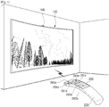
- FIG. 1 is a drawing illustrating an operation between a remote controller and a display apparatus, according to an exemplary embodiment.
- a display apparatus 100 and a remote controller (also referred to herein as a "remote control device") 200 are displayed.
- the display apparatus 100 may detect a user's motion via the use of a camera 145.
- the display apparatus 100 of which a screen is off may detect a user motion by using a camera 145.
- the display apparatus 100 when a user motion is detected, even before a user directly controls the remote controller 200 by holding it, may be in a pre-power on state in advance.
- a remote controller 200 may transmit a control command through infrared or near field communication (for example, Bluetooth) in order to control the display apparatus 100.
- infrared or near field communication for example, Bluetooth
- a user may control (for example, by performing any one or more of power on/off, booting, channel change, volume control, or content reproduction operations) the display apparatus 100 by using a selection of a key (including a button) on the remote controller 200 and by providing a user input (for example, any one or more or voice recognition through a touchpad, microphone, motion recognition through a sensor).
- a user may control (for example, by using any one or more of voice recognition through a touchpad, microphone, motion recognition through a sensor) the display apparatus 100 through a motion recognition by using a camera 145 attached to the display apparatus.
- a user by performing a motion (such as, for example, a gripping or moving) of the remote controller 200, may control a screen of the display apparatus 100.
- a user may control to operate a power off display apparatus 100 (for example, turn off a part of a screen) by gripping or moving the remote controller 200.
- a user may control to operate a power off display apparatus 100 (for example, turn on a part of a screen) by gripping or moving the remote controller 200.
- the display apparatus 100 may turn on a power supply to a screen. In response to a motion of the remote controller 200, the display apparatus 100 may turn on a power supply to a part of a screen. In response to a motion of the remote controller 200, power can be supplied to a part of a screen of the display apparatus 100.
- Items of information that relate to a display apparatus may include an output resolution (for example, high definition (HD), full HD, ultra HD or greater resolution) of the display apparatus 100, whether a screen is curved or flat, a display type (such as, for example, any of LCD (liquid crystal display), OLED (Organic Light Emitting Diodes), AMOLED (active matrix organic light-emitting diode), PDP (Plasma Display Panel), or QD (Quantum Dot)), a length of diagonal of a screen (for example, 66 cm, 80 cm, 101 cm, 152 cm, 189 cm, 200 cm or more), a width/length of the display apparatus 100 (for example, 643.4 mm x 396.5 mm, 934.0 mm x 548.6 mm, 1,670.2 mm x 962.7 mm, 2,004.3 mm x 1,635.9 mm), and/or a width/length ratio (also referred to herein as an "aspect ratio”) of the display apparatus 100 (
- the display apparatus information may indicate information that corresponds to a specification or a manual disclosed in a web page of the display apparatus 100.
- the display apparatus information can be stored in a storage 180 of the display apparatus 100.
- display apparatus information can be downloaded via the communicator 130 from outside of the display apparatus 100 through control of the controller 110 of the display apparatus 100.
- the remote controller 200 includes a key or a button 261 which corresponds to functions and/or operations of the display apparatus 100.
- a key 261 may include a physical button or a touch button.
- the remote controller 200 may include a single function key (for example, 261a, 261b, 261c, 261d, 261e) that corresponds to the functions of the display apparatus 100 and/or a multi function key (not shown).
- a single function key for example, a power button 261a, pointer 261e of the remote controller 200 can be used as a term indicating a key which corresponds to control of one function from among a plurality of functions executed by the display apparatus 100. Most of the keys in the remote controller 200 may be a single function key.
- a multi function key for example, a color key (not shown) of the remote controller 200 can be used as a term indicating a key which corresponds to control of subordinate functions which are variably provided (or set) according to functions executed by the display apparatus 100.
- a color key (not shown) may include a red key (not shown), a green key (not shown), a yellow key (not shown), and a blue key (not shown).
- An arrangement order of a color key (not shown) can be varied, and the number of the color key (not shown) can be added, changed, or deleted in response to a function of the display apparatus 100.
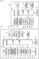
- FIG. 2 is a block diagram illustrating a display apparatus and a remote controller, according to an exemplary embodiment.
- the display apparatus 100 which receives control information from the remote controller 200 can be connected to an external e-device (not shown) with or without a wire by the communicator 130 or inputter/outputter 160.
- the external e-device may include a mobile phone (not shown), smartphone (not shown), a tablet PC (not shown), a PC (not shown), and a server (not shown).
- the display apparatus 100 includes the display 170 and may further include a tuner 120, the communicator 130, and inputter/outputter 160.
- the display apparatus 100 includes the display 170 and may further include a combination of the tuner 120, the communicator 130, and inputter/outputter 160.
- the display apparatus 100 including the display 170 can be electrically connected to a separate e-device (not shown) having a tuner (not shown).
- the display apparatus 100 may be implemented as any of an analog TV, digital TV, 3D-TV, smart TV, LED TV, OLED TV, plasma TV, monitor, a curved TV with fixed curvature, a flexible TV with a screen which is a fixed curvature, a bended TV with a screen which is a fixed curvature, and/or a curvature changeable TV of which curvature of a current screen can be changed by a received user input, but is not limited thereto. This could be easily understood by those of ordinary skill in the art.
- the display apparatus 100 includes tuner 120, the communicator 130, microphone 140, camera 145, optical receiver 150, inputter/outputter 160, the display 170, audio outputter 175, storage 180, and power supplier 190.
- the display apparatus 100 may include a sensor (for example, any of an illumination sensor, a temperature sensor, etc., not shown) which detects an internal state or an external state of the display apparatus 100.
- the controller 110 may include a processor 111, a read-only memory (ROM) (or non-volatile memory 112) where a control program for controlling the display apparatus 100 is stored, and a random-access memory (RAM) (or volatile memory, 113) which stores a signal or data which is input from an outside of the display apparatus 100, or is used as a storage area corresponding to various operations performed by the display apparatus 100.
- ROM read-only memory
- RAM random-access memory
- the controller 110 performs functions to control overall operations of the display apparatus 100, to control signal flow among internal components 120-190 of the display apparatus 100, and to process data.
- the controller 110 controls power provided to internal components 120-180 from the power supplier 190.
- the controller 110 may execute an operating system (OS) stored in the storage 180 and various applications.
- OS operating system
- the processor 111 may include a processor (such as, for example, a graphic processing unit (GPU), not shown) for graphic processing that corresponds to a video or an image.
- the processor 111 can be implemented as a system on chip (SoC) which includes a core (not shown) and a GPU.
- SoC system on chip
- the processor 111 can be implemented as a SoC which includes at least one of the ROM 112 and the RAM 113.
- the processor 111 may include any of a single core, dual core, triple core, quad core, and core which is N times.
- the processor 111 may include a plurality of processors.
- the plurality of processors may include a main processor (not shown) which operates in a pre-power on mode (see FIG. 7 ), a welcome mode ( FIG. 7 ) and/or a normal mode ( FIG. 7 ) which displays a broadcast screen that corresponds to one of the states of the display apparatus 100; and a sub processor (not shown) which operates in a screen off mode ( FIG. 7 ) and/or a pre-power on mode that corresponds to one of the states of another display apparatus 100.
- the pre-power on mode indicates a mode in which a user's motion is detected and a preparation is made for the display apparatus 100 to be activated
- a welcome mode indicates a mode to perform a corresponding operation when a user picks up the remote controller 200.
- the terms such as pre-power on mode and welcome mode can be substituted with different terms.
- a plurality of processors included in the controller 110 may operate or may not operate in response to a state of the display apparatus 100.
- a main processor (not shown) operates in a pre-power on mode, welcome mode and/or normal mode.
- the controller 110 which includes the main processor (not shown) can also operate.
- a sub processor (not shown) operates.
- the controller 110 which includes a sub processor (not shown) can be operated.
- a plurality of processors may include a main processor, a sub processor, and a sensor processor (not shown) which controls a sensor.
- a plurality of processors may include a main processor and a sensor processor (not shown).
- the processor 111, ROM 112, and RAM 113 can be interconnected via an internal bus.
- the controller 110 controls the user detector (e.g., camera 145) which detects a user motion, a display 170, a power supplier 190, and a communicator 130 which receives control information from a remote controller 200 and, in response to the detected user motion and first control information received from the remote controller 200, controls to display a preset screen on a part of the display 170, and in response to second control information received from the remote controller 200, controls to display a content on the display 170.
- the user detector e.g., camera 145
- a display 170 e.g., a display 170
- a power supplier 190 e.g., a power supplier 190
- a communicator 130 which receives control information from a remote controller 200 and, in response to the detected user motion and first control information received from the remote controller 200, controls to display a preset screen on a part of the display 170, and in response to second control information received from the remote controller 200, controls to display a content on the display 170.
- the controller 110 displays an image stored in the display apparatus on a portion of the display 170 at a first mode, and displays content from an external (apparatus) on a whole of the display 70 at a second mode.
- the controller 110 in response to the detected user motion, may control to change a state of the display apparatus from power off mode to a pre-power on mode, and the controller may control the power supplier 190 to supply power to all parts of the display apparatus except for the display 170.
- the controller 110 may control to receive the first control information via one of the communicator 130 and the optical receiver 150.
- the controller 110 in response to receipt of the first control information, may control the power supplier 190 to provide power to the display 170 and to display the preset screen on the display 170.
- the controller 110 may control so that the preset screen is displayed at a part of an area of the display 170 to which power is supplied.
- the controller 110 may control the power supplier 190 to supply power which is different from the power that is supplied to a preset screen to a remainder of an area of the display 170.
- the controller 110 in response to receipt of the first control information, may control the power supplier 190 to supply power to an audio outputter 175, and output auditory feedback to the audio outputter 175.
- the controller 110 may control to receive the second control information via one of the communicator 130 and the optical receiver 150.
- the controller 110 may control the power supplier 190 to continuously provide power to the user detector (e.g., camera 145).
- the user detector e.g., camera 145
- the controller 110 may include a main processor and a sub processor, and the user detector may be controlled by the sub processor.
- controller of the display apparatus 100 includes a processor 111, ROM 112, and RAM 113 of the display apparatus 100.
- the term “controller of the display apparatus 100” may include a main processor (not shown), a sub processor (not shown), ROM 112, and RAM 113 of the display apparatus 100.
- controller 110 could have been variously implemented according to exemplary embodiments may be easily understood by those of ordinary skill in the art.
- a tuner 120 may select a frequency of a channel which the display apparatus 100 wishes to receive, through amplification, mixing, and resonance of a broadcast signal which is received via wire or wirelessly.
- Broadcast signal includes video, audio, and additional data (for example, electronic program guide (EPG)).
- EPG electronic program guide
- the tuner 120 may receive video, audio, and/or data from a frequency band which corresponds to a channel number (for example, cable broadcast channel 605) that corresponds to a user input (for example, control information-channel number input received from the remote controller 200, channel up-down input, etc.).
- a channel number for example, cable broadcast channel 605
- a user input for example, control information-channel number input received from the remote controller 200, channel up-down input, etc.
- the tuner 120 may receive a broadcast signal from any of various sources, such as ground wave broadcasting, cable broadcasting, satellite broadcasting, and Internet broadcasting.
- the tuner 120 may receive a broadcast signal from sources such as analog broadcast or digital broadcast.
- the tuner 120 may be realized as an all-in-one type with the display apparatus 100 or a separate device (for example, a set-top box (not shown), or a tuner (not shown) connected to inputter/outputter 160).
- the communicator 130 may connect the display apparatus 100 with the remote controller 200 or the electronic device (not shown) by control of the controller 110.
- the controller 110 via the communicator 130, may download an application from outside or perform web browsing.
- the communicator 130 may receive control information that corresponds to control of the display apparatus 100 from the remote controller 200 by control of the controller 110.
- the communicator 130 in response to performances and structures of the display apparatus 100, may include any one of wire Ethernet 131, wireless local area network (LAN) communicator 132, and near field communicator 133.
- the communicator 130 may include the combination of Ethernet 131, wireless LAN communicator 132, and local network communicator 133.
- the communicator 130 may receive control information transmitted from the remote controller 200.
- the near field communicator 133 may receive control information transmitted from the remote controller 200 by control of the controller 110.
- a microphone 140 receives user's utterance.
- the microphone 140 may convert received voice to an electrical signal and output the electrical signal to the controller 110.
- User voice for example, may include voice that corresponds to a menu of the display apparatus 100 or control of functions.
- a scope of recognition of the microphone 140 may vary in response to a user's voice volume and an ambient environment (for example, speaker sound, nearby noise).
- the microphone 140 may be realized as an all-in-one type that is integral with the display apparatus 100, or can be separably implemented.
- the separated microphone 140 can be electrically connected to the display apparatus 100 via the communicator 130 or inputter/outputter 160.
- the camera 145 photographs a video (for example, serial frames) which corresponds to a user motion in a camera recognition scope.
- the user motion for example, can include any of a presence of a user (for example, a user appears in the camera recognition scope) a part of the body such as face, facial expression, hands, fist, and fingers or a motion of a part of the body of a user.
- the recognition scope of the camera 145 can be within a distance of between approximately 0.2 meters and 5 meters from the camera 145 to a user.
- the camera 145 may consist of a lens (not shown) and an image sensor (not shown).
- the camera 145 may support an optical zoom function and/or a digital zoom function that use a plurality of lenses and image processing.
- the camera 145 may be located at any one of an upper side, a lower side, a left side, and a right side of the display apparatus 100. In addition, the camera 145 may be located at any one of an upper central area, a lower central area, a lower central area, and a lower left area of the display apparatus 100.
- the camera 145 may photograph a user (or a user motion) in the display apparatus 100 which is powered off (except that a power plug is connected to a power consent) by supply of power of the power supplier 190.
- the camera 145 may convert a video photographed by control of the controller 110 to an electrical signal and output the electrical signal to the controller 110.
- the controller 110 by analyzing a photographed video, recognizes a user motion.
- the controller 110 by using a motion recognition result, may display a menu on the display apparatus 100 or perform a control (for example, channel adjustment or volume adjustment, etc.) that corresponds to the motion recognition result.
- the camera 145 includes a plurality of cameras, in a front surface of the display apparatus 100, by using a second camera (not shown) which is adjacent (for example, space between the first camera (not shown) and a second camera (not shown) is greater than 10 mm and less than 80 mm) to the first camera(not shown), a 3D still image or a 3D motion can be received.
- a second camera which is adjacent (for example, space between the first camera (not shown) and a second camera (not shown) is greater than 10 mm and less than 80 mm) to the first camera(not shown)
- the camera 145 may be implemented as an all-in-one type that is integrated with the display apparatus 100 or may be separated.
- the electronic device (not shown) including the separated camera can be electrically connected to the display apparatus 100 via inputter/outputter 160.
- the optical receiver 150 receives an optical signal (which may include control information) output from the remote controller 200 via a wide window (not shown).
- the optical receiver 150 may receive, from the remote controller 200, an optical signal which corresponds to user input (for example, any of a touch, a press, a touch gesture, voice, or motion). From the received optical signal, control information can be extracted. A received optical signal and/or extracted control information can be transmitted to the controller 110.
- an optical signal which corresponds to user input (for example, any of a touch, a press, a touch gesture, voice, or motion).
- control information can be extracted.
- a received optical signal and/or extracted control information can be transmitted to the controller 110.
- the inputter/outputter 160 by control of the controller 110, receives contents from outside of the display apparatus 100.
- Contents may include any of video content, an image, text, or a web document.
- contents may include video that includes advertisements, an image that includes an advertisement, or web documents that include advertisements.
- the inputter/outputter 160 may include an HDMI input port (High-Definition Multimedia Interface port) 161 that corresponds to receipt of contents, a component input jack 162, a PC input port 163, and a USB input jack 164.
- the inputter/outputter 160 may be added, deleted and/or changed according to performances and structure of the display apparatus 100, and this may be easily understood by those of ordinary skill in the art.
- the display 170 displays video included in a broadcast signal received via the tuner 120 by the control of the controller 110.
- the display 170 may display contents (for example, video) input via the communicator 130 or inputter/outputter 160.
- the display 170 may output contents stored in the storage 180 by the control of the controller 110.
- the display 170 may display a voice user interface (UI) for performing a voice recognition task that corresponds to voice recognition or a motion UI for performing a motion recognition task.
- voice UI may include a voice command guide and the motion UI may include a motion command guide.
- a screen of the display apparatus 100 may be used as a term that includes the display 170 of the display apparatus 100.
- the display 170 may display a welcome screen that corresponds to the first control signal received from the remote controller 200 by the control of the controller 110.
- the display 170 may be separated from the display apparatus 100.
- the display 170, via the inputter/outputter 160 of the display apparatus 100, may be electrically connected to the display apparatus 100.
- An audio outputter 175 outputs audio included in a broadcast signal received via the tuner 120 by the control of the controller 110.
- the audio outputter 175 may output audio (for example, audio that corresponds to voice and sound) input via the communicator 130 or the inputter/outputter 160.
- the audio outputter 175 may output an audio file stored in the storage 180 by the control of the controller 110.
- the audio outputter 175 may include any one of a speaker 176, a headphone output terminal 177, or an S/PDIF output terminal 178. In addition, the audio outputter 175 may include a combination of a speaker 176, a headphone output terminal 177, and/or an S/PDIF output terminal 178.
- the audio outputter 17 may output auditory feedback that corresponds to a display of a welcome screen according to the first control signal received from the remote controller 200 by the control of the controller 110 of the display apparatus 100.
- the storage 180 may store various data, programs, and/or applications to drive and control the display apparatus 100.
- the storage 180 may store an input/output signal and/or data that corresponds to the tuner 120, the communicator 130, the microphone 140, the camera 145, the optical receiver 150, inputter/outputter 160, the display 170, audio outputter 175, and the power supplier 190.
- the storage 180 may store any one or more of a control program for controlling the display apparatus 100 and the controller 110, an application initially provided by a manufacturer or downloaded from outside, a GUI related to an application, an object for providing GUI (for example, image text, icon, button, etc.), user information, documents, database, and/or relevant data.
- a control program for controlling the display apparatus 100 and the controller 110
- an application initially provided by a manufacturer or downloaded from outside a GUI related to an application
- an object for providing GUI for example, image text, icon, button, etc.
- user information for example, image text, icon, button, etc.
- the storage 180 may include any one or more of a broadcast receipt module, a channel control module, a volume control module, a communication control module, a voice recognition module, a motion recognition module, an optical receipt module, a display control module, an audio control module, an external input control module, a power control module, a voice database, and/or a motion database which are not illustrated.
- Not illustrated modules of storage unit and database may be implemented as software which is configured to perform any one or more of a broadcast receipt control function, a channel control function, a volume control function, a communication control function, a voice recognition function, a motion recognition function, an optical receipt control function, a display control function, an audio control function, an external input control function, and/or a power control function of the display apparatus 100.
- the controller 110 by using the software stored in the storage 280, may perform a function of the display apparatus 100.
- the storage 180 may store display apparatus information and/or remote controller information.
- the storage 180 may store video, image, and/or text that corresponds to visual feedback.
- the storage 180 may store sound that corresponds to auditory feedback.
- the storage 180 may store a feedback providing time (for example, 300 ms) of feedback provided to a user.
- the term “storage” can be used to include any of the storage 180, storage (not shown) implemented as ROM 112, RAM 113, SoC (not shown) of the controller 110, memory card (for example, micro SD card, USB memory (not shown)) stored in the display apparatus 100, and/or external storage unit connectable to the USB port 164 (for example, USB memory (not shown)) of the inputter/ outputter 160.
- the storage may include any of non-volatile memory, volatile memory, hard disk drive (HDD), and/or solid state drive (SDD).
- the power supply 190 supplies power input from an external power source to the components 110-190 inside the display apparatus 100 by the control of the controller 110.
- a power supplier 190 by the control of the controller 110, may provide power input from one or two or more batteries (not shown) to internal components 120-190 located inside the display apparatus 100.
- the power supplier 190 may include the first power supplier (not shown) which supplies power to the camera 145 of the display apparatus 100 which is powered off (or only the screen of the display apparatus 100 is powered off, while the power plug is connected to a power consent) and to a sub processor (not shown) or a sensor processor which controls the camera 145 of the display apparatus.
- the power supplier 190 may include a battery (not shown) which provides power to the camera 145 of the display apparatus 100 which is powered off (except that a power plug is connected to a power consent).
- At least one component in response to performances and/or types of the display apparatus 100, at least one component can be added, changed, or deleted (for example, at least one of a box illustrated in dotted lines).
- the respective locations (for example, 120-190) of the components can be changed in response to performances or structure of the display apparatus 100 may be easily understood by those of ordinary skill in the art.
- the remote controller 200 which remotely controls the display apparatus 100 includes a controller 210, a communicator 230, an inputter 260, an optical outputter 250, a display 270, a storage 280, and a power supplier 290.
- the remote controller 200 may include one of the communicator 230 and the optical outputter 250.
- the remote controller 200 may include all of the communicator 230 and the optical outputter 250.
- the remote controller 200 may be used as a term which indicates an electronic device which can control the display apparatus 100.
- the remote controller 200 may include an electronic device which can install (or download from outside) an application (not shown) for controlling the display apparatus 100.
- the electronic device which can install the application (not shown) for control of the display apparatus 100 can include a display (for example, there is only a display panel without a touch screen or a touch panel).
- the electronic device having a display may include any of a cell phone (not shown), smart phone (not shown), tablet PC (not shown), note PC (not shown), other display apparatuses (not shown), and/or home appliances (for example, refrigerator, washing machine, or cleaning machine).
- a user may control the display apparatus 100 by using a function key (for example, a channel key (not shown) in a graphic user interface (GUI, not shown) provided by the application which is running.
- a function key for example, a channel key (not shown) in a graphic user interface (GUI, not shown) provided by the application which is running.
- GUI graphic user interface
- the controller 210 may include a processor 211, ROM (or non-volatile memory) 212 where a control program to control the remote controller 200 is stored, and RAM (or volatile memory) 213 which stores a signal or data input from outside the remote controller 200 or used as a storage area for various jobs executed in the remote controller 200.
- ROM or non-volatile memory
- RAM or volatile memory
- the controller 210 controls overall operations of the remote controller 200 and signal flow among internal components 220-290 of the remote controller 200, and performs a function to process data.
- the controller 210 controls a power supply to internal components 220-290 by using the power supplier 290.
- the controller 210 controls a sensor to detect a motion of the remote controller, a power button to turn on the display apparatus, a communicator connected to the display apparatus, the sensor, and the communicator, and controls to transmit first control information which corresponds to a motion of the detected remote controller and second control information which corresponds to a selection of the power button to the display apparatus via the communicator.
- the controller 210 may control a transmission of at least one of the first control information and the second control information to the display apparatus via the optical outputter 250.
- the controller 210 may provide haptic feedback and auditory feedback in response to at least one of the transmission of the first control signal and the second control signal.
- the term "the controller 210" may include the processor 211 of the remote controller 200, ROM 212, and RAM 213.
- the communicator 230 may transmit the control information (for example, control information that corresponds to power on, or control information that corresponds to a motion of the remote controller) which corresponds to user input (for example, a touch, a press, a gesture, a voice, or a motion) to the display apparatus 100.
- the communicator 230 by the control of the controller 210, may be wirelessly connected to the display apparatus 100.
- the communicator 230 may include at least one of the wireless LAN communicator 231 and near field communicator 232 (for example, one of wireless LAN communicator 231 and near field communicator 232, or both of the wireless LAN communicator 231 and near field communicator 232).
- Wireless LAN 231 can be wirelessly connected to AP by control of the controller 210 at a place where AP is installed.
- the wireless LAN 131 may include wireless fidelity (Wi-Fi).
- the wireless LAN 131 supports wireless LAN (IEEE802.11x) of IEEE.
- the near field communicator 132 may be connected via near field communication between the mobile device 100 and an external device wireless without AP by the control of the controller 110.
- Near field communication for example, may include any of Bluetooth, Bluetooth low energy, infrared data association (IrDA), Ultra Wideband (UWB), or near field communication (NFC).
- the inputter 260 may include a button 261 and/or a touch pad 262 configured to receive an input (for example, a touch or a press) of a user for control of the display apparatus 100.
- the inputter 260 may include the microphone 263 which receives uttered user voice, the sensor 264 for detecting a motion of the remote controller 200, and/or a vibration motor (not shown) providing haptic feedback.
- the inputter 260 may output an electrical signal (for example, an analog signal or a digital signal) that corresponds to a received user input (for example, a touch, a press, a touch gesture, a voice, or a motion) to the controller 210.
- an electrical signal for example, an analog signal or a digital signal
- a received user input for example, a touch, a press, a touch gesture, a voice, or a motion
- a button 261 may include buttons 261a, 261b, 261c, 261d, 261e of FIG. 1 .
- the touch pad 262 may receive a user touch or user's touch gesture. Referring also to FIG. 1 , the touch pad 262 can be implemented as an area where a direction key 262a and an enter key 262b are located. In addition, the touch pad 262 can be located at a front surface of the remote controller 200 where keys 261a to 261e are not located.
- the microphone 263 receives a user's uttered voice.
- the microphone 263 may convert received voice to an electrical signal and output the converted electrical signal to the controller 210.
- the sensor 264 may detect an internal state and/or external state of the remote controller 200.
- a state can be respectively measured by a motion sensor (not shown) which detects a motion of the remote controller 200, a gyro sensor (not shown) which detects a direction by using a rotation inertia of the remote controller 200, an acceleration sensor (not shown) which detects a speed and/or a rate of acceleration of three axes (for example, X-axis, Y-axis, and Z-axis) added to the remote controller 200, or a gravity sensor which detects a direction of gravity.
- the sensor 264 may respectively measure motion acceleration speed or gravity acceleration speed of the remote controller 200.
- the senor 264 may detect a motion (or an acceleration or a speed) of the remote controller 200 caused by a user.
- the controller 210 may generate a control signal that corresponds to a motion of the remote controller 200 and transmit the communicator 230 to the display apparatus 100.
- a vibration motor may convert an electrical signal to a mechanical vibration by the control of the controller 210.
- the vibration motor may include any of a linear vibration motor, a bar-type vibration motor, a coin-type vibration motor, and/or a piezoelectric element.
- the controller 210 of the remote controller 200 can operate a vibration motor (not shown).
- One or more vibration motors(not shown) can be located inside the remote controller 200.
- the vibration motor(not shown) can cause the entire remote controller 200 to vibrate or cause a part of the remote controller 200 to vibrate.
- the vibration motor may output haptic feedback that corresponds to a transmission of control information according to control of the controller 210. Based on control information transmitted by the control of the controller 210, the vibration motor(not shown) can provide various types of haptic feedback (such as, for example, strength of vibration corresponding to various haptic patterns and vibration continuation time stored in the storage 280).
- the optical outputter 250 outputs an optical signal (for example, including control information) that corresponds to user input (for example, a touch, a press, a touch gesture, a voice, or a motion) by the control of the controller 210.
- the outputted optical signal can be received at the optical receiver 150 of the display apparatus 100.
- a remote controller code format used in the remote controller 200 may include one of a manufacturer-exclusive remote controller code format and a commercial remote controller code format.
- the remote controller code format may include a leader code and data word.
- the outputted optical signal can be modulated by carrier wave and outputted. Control information can be stored in the storage 280 or may be generated by the controller 210.
- the remote controller 200 may include IR-LED (infrared-laser emitting diode).
- the remote controller 200 may include one or both of the communicator 230 which can transmit control information to the display apparatus 100 and the optical outputter 250.
- the controller 210 may output control information that corresponds to a user input to the display apparatus 100 via one of the communicator 230 and the optical outputter 250. In addition, the controller 210 may output control information that corresponds to a motion of the remote controller 200 to the display apparatus 100 via one of the communicator 230 and the optical outputter 250.
- the controller 210 may transmit, to the display apparatus 100, control information that corresponds to a user input and/or control information that corresponds to a motion of the remote controller 200 in a prior manner via one of the communicator 230 and the optical outputter 250 (for example, the communicator 230).
- the display 270 may include a display in types of any of an LCD (liquid crystal display), an OLED (Organic Light Emitting Diodes), a PDP (Plasma Display Panel), and/or a VFD (Vacuum fluorescent display).
- LCD liquid crystal display
- OLED Organic Light Emitting Diodes
- PDP Plasma Display Panel
- VFD Vauum fluorescent display
- the display 270 may display a broadcast channel number, a broadcast channel name displayed on the display apparatus 100, and/or a state of the display apparatus (for example, screen off, pre-power mode, welcome mode and/or normal mode).
- a state of the display apparatus for example, screen off, pre-power mode, welcome mode and/or normal mode.
- the display 270 may display a text that indicates "BT connected” or "NFC connected” by control of the controller 210.
- the display 270 may display text, an icon, or a symbol that corresponds to, by the control of the controller 210, "TV on” to indicate a turning on power of the display apparatus 100, “TV off” to indicate a powering off the display apparatus 100, display selected channel numbers “Ch No.”, and/or "Vol value” to indicate an adjusted volume.
- the storage 280 may store various data, programs, and/or applications to drive and control the remote controller 200 by the control of the controller 210.
- the storage 280 may store input or output signals and/or data that corresponds to driving of the communicator 230, optical outputter 250, and power supplier 290.
- the storage 280 may store control information that corresponds to a user input (for example, a touch, a press, a touch gesture, a voice, or a motion) received by the control of the controller 210 and/or control information that corresponds to a motion of the remote controller 200.
- the storage 280 may store information that relates to a remote controller that corresponds to the remote controller 200.
- the remote controller information may include any of a model name, a device identification (ID), a remaining memory amount, object data existence, a Bluetooth version, and/or a Bluetooth profile.
- the storage 280 may store the first control information which corresponds to a motion of the remote controller 200 which is transmitted to the display apparatus 100.
- the first control information may include a group of each of the first control information that corresponds to a motion of the remote controller 200.
- the storage 280 may store the second control information that corresponds to a selection of a power button 261a transmitted to the display apparatus 100.
- the storage 280 may store one or two or more haptic patterns.
- the haptic patterns can be expressed as a wave form.
- the haptic patterns may indicate a vibration time (for example, a unit is 50 ms) of a vibration motor (not shown) in a width axis, and a strength of vibration (for example, a unit is 500 mV) of a vibration motor (not shown) in a length axis.
- the first haptic pattern may be a vibration which gradually increases from 0 V to 800 mV, gradually decreases to 100 mV, and repeatedly increases again.
- a speed increasing section and a speed decreasing section may be symmetrical.
- the second haptic pattern may be a vibration which gradually increases from 0 V to 900 mV, sharply decreases to 500 mV, gradually decreases 200 mV, and increases again.
- the third haptic pattern may be a vibration which gradually increases from 0 V to 950 mV, sharply decreases to 100 mV, and then increases again.
- one pattern from among a plurality of haptic patterns can be stored as a favorite haptic pattern.
- the controller 210 may provide haptic feedback via a vibration motor (not shown) with the favorite haptic pattern being preferentially employed.
- haptic pattern In response to a function or structure of the remote controller 200, that the haptic pattern can be added, changed, or deleted may be easily understood by those of ordinary skill in the art.
- the power supplier 290 provides power to the components 220-290 of the remote controller 200 by the control of the controller 210.
- the power supplier 290 may supply power to the components 210-290 from one or two or more batteries (not shown) located in the remote controller 210.
- a battery can be located at a surface (for example, there is a key 261 or a touch pad 262) of the remote controller 200, or an inner side between the surface and a rear side (not shown).
- the components illustrated in the remote controller 200 of FIGS. 1 and 2 can be added or deleted (for example, at least a box in a dotted line) in response to the performance of the remote controller 200.
- respective positions of the components can be changed in response to a performance or a structure of the remote controller 200 may be easily understood by those of ordinary skill in the art.
- FIG. 3 is a flowchart illustrating a method for controlling a screen of a display apparatus, according to an exemplary embodiment.
- FIG. 4 is a sequence diagram illustrating a method for controlling a screen of a display apparatus, according to an exemplary embodiment.
- FIGS. 5A , 5B , 5C , 5D , and 5E are drawings illustrating a method for controlling a screen of a display apparatus, according to an exemplary embodiment.
- the display apparatus and the remote controller are connected via near field communication, and a screen of the display apparatus is powered off.
- the display apparatus 100 is connected to the remote controller 200 via near field communication (operation 401).
- the display apparatus 100 and the remote controller 200 are connected via near field communication.
- the controller 210 of the remote controller 200 by using a near field communicator (for example, Bluetooth 132), may search the display apparatus 100.
- the controller 210 of the remote controller 200 can query the display apparatus 100 and request a connection (page) for the queried display apparatus 100.
- the storage 280 may store connection information of the display apparatus that corresponds to the display apparatus 100 connected to the remote controller 200 by the control of the controller 210.
- the stored display apparatus connection information may include any of an SSID of an identifier (identification information) of a display apparatus, a MAC address, a model name, a manufacturer, operation information (for example, busy, standby, etc.), capability, version, and/or context information.
- an advertising packet may include an SSID of an identifier (identification information) of a display apparatus, a MAC address, a model name, a manufacturer, operation information (for example, busy, standby, etc.), capability, version, and/or context information.
- the advertising packet transmitted from the display apparatus 100 to the outside is one exemplary embodiment and is not limited thereto. It may be sufficient that the advertising packet includes a part or whole of display apparatus information which includes identification information of the display apparatus 100.
- the remote controller 200 may analyze a part or whole of the received display apparatus information and connect with the display apparatus 100 through near field communication.
- the controller 210 of the remote controller 200 may transmit control information to the display apparatus 100 by using display apparatus connection information.
- a screen of the display apparatus is powered off (operation 402).
- a screen of the display apparatus 100 can be powered off by a user.
- a screen of the display apparatus 100 can be powered off by using the remote controller 200.
- a screen of the display apparatus 100 can be powered off by a operation of a panel key (not shown) positioned in a rear side (for example, a surface of a bottom sash) of the display apparatus 100.
- the display apparatus 100 When a screen of the display apparatus 100 is powered off (or the display apparatus 100 is powered off), the display apparatus 100 is connected to a power consent via a power cable. When a screen of the display apparatus 100 is powered off (or the display apparatus 100 is powered off), power can be provided to a sub processor (not shown).
- the camera 145 of the display apparatus 100 of which screen is power off can be supplied with power by the first power supplier (not shown).
- the camera 145 of the display apparatus 100 for which the screen is powered off by the first power supplier (not shown) and a sub processor (not shown) which controls the camera 145 can be supplied with power continuously.
- a user motion is not detected.
- a screen of the display apparatus 100 is powered off, a connection between the display apparatus 100 and the remote controller 200 through near field communication can be maintained or disconnected.
- a presence of a user can be detected by the camera 145 of the display apparatus 100 (operation 403).
- a user can enter into a recognition scope of the camera 145 of the display apparatus 100.
- the camera 145 may photograph a user motion (i.e., a user's presence (for example, a user makes a presence in a camera recognition scope), a part of a user's body such as a user's face, facial expression, hands, fist, or a motion of a part of a user's body in a frame unit (for example, 15, 30, 60 frames per second, changeable).
- the camera 145 may transmit data that corresponds to a user motion to a sub processor (not shown).
- the camera 145 may photograph a previous frame (for example, a user is not present) and a current frame (for example, a user is present).
- the sub processor (not shown) which controls the camera 145 can analyze each of the photographed frame.
- the sub processor (not shown) may compare and analyze a previous frame (for example, a user is not present) with respect to a current frame (for example, the user is present).
- the sub processor (not shown) may detect a user motion through analysis.
- the display apparatus 100 may include a separate exclusive processor (not shown) which controls the camera 145.
- the exclusive processor may analyze and detect a user motion.
- the sub processor may control other components (for example, a sensor or the first power supplier, etc.) other than the camera 145.
- the camera 145 is used for detecting a user motion (for example, presence of a user, etc.), however, not only the camera 145 but also any of a radio frequency sensor (RF sensor, not shown) which uses the Doppler effect, a pyroelectric infrared sensor (PIR sensor, not shown) which uses infrared rays and/or the microphone 140 can be used, as may be easily understood by those of ordinary skill in the art.
- RF sensor radio frequency sensor
- PIR sensor pyroelectric infrared sensor
- the camera 145 which detects a user motion and various sensors can be referred to as the user detectors.
- the operational mode of the display apparatus is changed to a pre-power on mode.
- the operational mode of the display apparatus 100 can be changed from a screen off to a pre-power on mode (operation 404).
- a sub processor can wake up a main processor (not shown).
- the exclusive processor (not shown) of the camera 145 can wake up the main processor (not shown).
- the controller 110 of the display apparatus 100 can change to a pre-power on mode.
- a state of the display apparatus 100 can be changed to a pre-power on mode after time of 0.3 second to 1 second elapses.
- a screen is continuously powered off (for example, a screen is not woken up).
- the controller 110 may control the power supplier 190 not to supply power to the screen (the display 170).
- the controller 110 in contrast to a normal mode (for example, power consumption is different) where a broadcast channel is displayed on a screen 170, may control the power supplier 190 to supply power.
- the audio outputter 175 may be powered off (for example, it may not be woken up).
- the controller 110 may control the power supplier 190 not to supply power to the audio outputter 175.
- the controller 110 in contrast (for example, power consumption is different) to a normal mode which outputs sound to the audio outputter 190, may control the power supplier 190 to supply power.
- the storage 180 may store user motion detection information by the control of the controller 110.
- the user motion detection information may include any of a user motion detection ID for history management, a user motion detection time, a detected user motion (for example, user authentication through face recognition), and/or a pre-power on mode change time, etc.
- a state of the display apparatus 100 may return to a screen power off mode from a pre-power on mode.
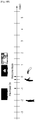
- a control signal that corresponds to a detection of a motion of the remote controller is received through near field communication.
- a motion of a remote controller is detected (operation 405).
- a user may grip and move the remote controller 200 which has been placed on a table.
- a user who is detected by the user detector of the display apparatus 100 may grip and move the remote controller 200 which has been placed on a table.
- a user may move the remote controller 200 from a first position 200a1 to a second position 200a2.
- the controller 210 of the remote controller 200 may detect a motion (or acceleration, speed, etc.) of the remote controller 200.
- a motion of the remote controller 200 is detected by the sensor 264.
- a movement of the remote controller 200 can be periodically detected (for example, movement of the remote controller 200 can be detected by a sensor).
- the sensor 264 in response to a movement of the remote controller 200, may output an analog signal to the controller 210.
- an analog signal output from the sensor 264 can be converted to a digital signal by a converter (not shown).
- the converted digital signal can be output to the controller 210.
- the controller 210 of the remote controller 200 may analyze a signal received from the sensor 264 and determine a movement of the remote controller 200 (for example, a change in a moving distance or acceleration speed, etc.).
- the storage 280 may store an analog signal detected by the controller of the controller 210 or a digital signal converted from the analog signal.
- s stored analog signal or digital signal is referred to as "remote controller motion detection information”.
- Stored remote controller motion detection information may include a remote controller motion ID for history management, an acceleration value of the detected remote controller 200 (for example, 2 axis or 3 axis), a movement detection time of the remote controller 200, and/or a moving distance of the remote controller 200.
- the remote controller motion detection information can be periodically stored, starting from the first position 200a1 of the remote controller 200 to the second position 200a2.
- the remote controller motion detection information may include a group of remote controller motion detection information which is stored in response to resolution of the sensor 264 and/or movement of the remote controller 200 in a detectable time interval.
- the controller 210 may generate first control information by using the stored remote controller motion detection information.
- the controller 210 by using remote controller motion detection information which is periodically stored, may generate the first control information.
- the first control information may be generated from the first position 200a1 to the second position 200a2.
- the controller 210 by using stored remote controller motion detection information, may load or select the first control information stored in the storage 280.
- the first control information may include the control information which can display a welcome screen 171 (see FIG. 5D ) on a screen of the display apparatus 100.
- the controller 210 may transmit the first control information to the display apparatus 100 (operation 406).
- the controller 210 may periodically transmit the first control information to the display apparatus 100 via one of the communicator 230 and the optical outputter 250. In addition, the controller 210 may periodically transmit the first control information which is generated from the first position 200a1 of the remote controller 200 to the second position 200a2.
- a user may move the remote controller 200 for a set time.
- the set time may be 300 ms (changeable upon setting).
- the setting time that corresponds to the first control information may indicate that, for a longer time than a signal frequency from the first leader code of the remote controller code format to a subsequent second leader code (for example, before a continuous code subsequent to the second leader code is output), the remote controller 200 is moved by a user.
- That the setting time may vary according to a model or a manufacturer of the remote controller 200 may be easily understood by those of ordinary skill in the art.
- the controller 210 of the remote controller 200 may transmit the first control information to the display apparatus 100 in a Bluetooth packet (not shown) type.
- Bluetooth (not shown) includes an access code (72 bit) for determining whether a packet is valid, a header (54 bit) and a payload 0-2, 745 bit).
- the access code is used for whether packet is valid or not.
- the header includes a MAC (media access control) address and a packet type.
- the payload includes data to be transmitted, and a size of the payload varies according to a type of packets to be transmitted. Transmitted first control information may be included in a payload of a packet.
- the communicator 130 of the display apparatus 100 may receive the first control information from the remote controller 200 by control of the controller 110.
- the display apparatus 100 may receive the first control information which is output from the remote controller 200 via the communicator 130.
- the display apparatus 100 receives the first control information output from the remote controller 200 via the optical receiver 150.
- the received first control information may be stored in the storage 180 by control of the controller 110.
- a welcome screen which corresponds to a welcome mode is displayed on a screen of the display apparatus.
- a welcome screen 171 which corresponds to a welcome mode is displayed on a screen of the display apparatus 100 (operation 407).
- the controller 110 of the display apparatus 100 in response to receipt of the received control information, may change a state of the display apparatus 100 from a pre-power on mode to a welcome mode.
- the controller 110 of the display apparatus 100 can display a state of the display apparatus 100 on a welcome screen 171 after a time interval of 0.1 second to 0.4 second elapses.
- the controller 110 of the display apparatus 100 may change a pre-power on mode to a welcome mode of the display apparatus 100 before a welcome screen 171 is displayed on the display apparatus 100.
- the controller 110 may control to supply power to a screen (i.e., a display).
- the controller 110 may control the power supplier 190 to supply power to a screen 170 to correspond to a welcome mode which is different from a pre-power on mode (for example, power consumption is different).
- the controller 110 may control to supply power to the audio outputter 175.
- the controller 110 may control the power supplier 190 to supply power to the audio outputter 175 to correspond to a welcome mode which is different from a pre-power on mode (for example, power consumption is different).
- the storage 180 may store the first control information by the control of the controller 110.
- the controller 110 of the display apparatus 100 may display the welcome screen 171 that corresponds to a change of a welcome mode on a screen.
- the welcome screen 171 can be named a preset screen.
- the welcome screen 171 may be a screen which is displayed to correspond to a change in an operational mode from a pre-power on mode to a welcome mode.
- the welcome screen 171 may be displayed as a shape which is set on a part of an area (for example, a central area of a screen) of the display apparatus 100.
- the remainder of the area on the display apparatus 100 may be background (for example, power off background).
- the welcome screen 171 can be displayed by using power which is supplied to a part of an area of a screen of the display apparatus 100 by control of the controller 110.
- the welcome screen 171, which is different (for example, power consumption is different) from contents which are displayed on a screen 170 in a normal mode, may be a screen to which power is supplied to a part of the screen 170.
- power can be supplied in variable amounts by control of the controller 110.
- the controller 110 may control the power supplier 190 so that power is supplied differently at a rest of the area on a screen of the display apparatus 100 until the second control signal is received.
- the rest of the area can be displayed to be black, as power is supplied in variable amounts by control of the controller 110.
- the partitioning of an area of a screen can be one of a left area and a right area when a screen is divided into two by equal division.
- a part of the area of a screen, when a screen is divided into upper and lower parts, can be one of an upper area and a lower area.
- a part of an area of the screen can be at least one of a left area, a central area, and a right area.
- a part of the area of a screen, when a screen is divided into three areas, the area can be at least one of an upper area, a central area, and a lower area.
- a part of an area of a screen can be at least one of, when a screen is divided into four parts, a left quarter area, a central left quarter area, a central right quarter area and a right quarter area.
- the part of the area described above is merely an exemplary embodiment, and that it can be applied to the case where a screen is divided into left and right to five or more parts, or into upper and lower parts to five or more parts (for example, division into 10 parts, 20 parts, etc.) may be easily understood by those of ordinary skill in the art.
- a part of a screen can be divided into a matrix area (m X n, where m and n are natural numbers, for example, any of 2 X 2, 2 X 3, 3 X 3, 3 X 4, 4 X 4, 4 X 5, 5 X 5, such that the arrangement may be changed) may be easily understood by those of ordinary skill in the art.
- the welcome screen 171 can be displayed at a part of an area of a corner of a screen of the display apparatus 100.
- the set shape of the welcome screen 171 may include any of a circle shape, an oval shape, and polygonal shape that includes an image on a surface.
- the set format of the welcome screen may be a 3D format which is displayed by a depth value on a 2D screen.
- the set shape of the welcome screen 171 can be displayed on a part of an area of the aforementioned screen.
- the set format of the welcome screen 171 may be displayed at a part of an area of a corner of the abovementioned screen.
- the welcome screen 171 is displayed as a format which is set on a part of an area of a screen, and additional information 171a can be displayed together with the welcome screen 171.
- additional information 171a may include time, data, weather (for example, see FIG. 5F ), a greeting message (for example, see FIG. 5G ) or set text (for example, today's schedule, contact list).
- time, data for example, see FIG. 5F
- greeting message for example, see FIG. 5G
- set text for example, today's schedule, contact list
- additional information 171a can be displayed together.
- a side of the set format can be a side inside the rectangular shape or a side outside the rectangular shape.
- the controller 110 may provide visual feedback, such as an animation effect, to the welcome screen 171 displayed on a screen.
- the controller 110 in response to the displaying of the welcome screen 171, may provide auditory feedback via the audio outputter 175 to which power is supplied.
- auditory feedback via the audio outputter 175 to which power is supplied.
- visual feedback and auditory feedback can be provided.
- a state of the display apparatus 100 can be changed from a welcome mode to a pre-power on mode.
- a state of the display apparatus 100 can change to a screen power off mode.
- a control signal that corresponds to a power button input is received from the remote controller.
- a power button 261a of the remote controller 200 receives a user input (operation 408).
- a user may select a power button 261a of the remote controller 200.
- a user who is detected by the user detector of the display apparatus 100 can select a power button 261a of the remote controller 200.
- Selection of the power button 261a may include a press of the power button 261a, a touch of the power button 261a, and/or a touch gesture of the power button 261a.
- selection of the power button 261a can include a user voice input through the microphone 263 or a user gesture (for example, gripping the remote controller 200 and drawing a circle) detected by sensor 264.
- the controller 210 of the remote controller 200 can store "power button selection information" that corresponds to the selection of the button 261a at the storage 280.
- the stored power button selection information may include power button selection information ID for history management, and/or power button selection time, and/or the like.
- the controller 210 by using stored power button selection information, may generate the second control information.
- the controller 210 by using the stored power button selection information, may load or select the second control information which is stored at the storage 280.
- the second control information may include control information which may display contents (for example, broadcast channel, video 300) on a screen of the display apparatus 100.
- the controller 210 may transmit the second control information to the display apparatus 100 (operation 409).
- the controller 210 may transmit the second control information periodically to the display apparatus 100 by using one of the communicator 230 and the optical outputter 250.
- the setting time can be 300 ms (changeable upon setting).
- the setting time that corresponds to the second control information may indicate that, for a longer time than a signal frequency from the first leader code of the remote controller code format to a subsequent second leader code (for example, before a continuous code subsequent to the second leader code is output), the power button 261a is selected by a user.
- That the setting time may vary according to a model or a manufacturer of the remote controller 200 may be easily understood by those of ordinary skill in the art.
- the controller 210 of the remote controller 200 may transmit the second control information to the display apparatus 100 in a Bluetooth packet (not shown) type.
- the communicator 130 of the display apparatus 100 may receive the second control information from the remote controller 200.
- the display apparatus 100 may receive the second control information which is output from the remote controller 200 via the communicator 130.
- the display apparatus 100 receives the second control information which is output from the remote controller 200 via the optical receiver 150.
- the received second control information may be stored in the storage 180 by the control of the controller 110.
- a broadcast channel is displayed on a screen of a display apparatus.
- the welcome screen 171 disappears from a screen of the display apparatus 100, and broadcast channel (for example, cable broadcast channel 228-1, 300) is displayed (operation 410).
- broadcast channel for example, cable broadcast channel 228-1, 300
- the welcome screen 171 may disappear and contents can be displayed.
- a video, an image, or a webpage through not only broadcasting but also applications installed on the display apparatus 100 can be included.
- the controller 110 of the display apparatus 100 can change a state of the display apparatus 100 from a welcome mode to a normal mode in response to the received second control information.
- the controller 110 of the display apparatus 100 may display a state of the display apparatus 100 on a broadcast screen 300 when a time interval of 0.05 seconds to 0.3 seconds has elapsed.
- the controller 110 of the display apparatus 100 may change a state of the display apparatus 100 from a welcome mode to a normal mode.
- a respective power consumption amount of the display apparatus 100 may vary based on the operational mode.
- power consumption may vary by partial or whole operation of the display 170.
- the storage 180 may store the second control information by the control of the controller 110.
- the controller 110 in response to contents display on a screen, may provide visual feedback, such as, for example, the animation effect.
- the controller 110 in response to contents display, may provide auditory feedback.
- a method for controlling a screen of the display apparatus may end.
- FIGS. 6A and 6B are drawings illustrating examples of a method for controlling a screen of a display apparatus as a function of time, in accordance with an exemplary embodiment.
- FIG. 7 is a drawing illustrating a power consumption sequence associated with a method for controlling a screen of the display apparatus, according to an exemplary embodiment.
- FIG. 6A illustrates a method for controlling a screen of a normal display apparatus
- FIG. 6B illustrates a method for controlling a screen of a display apparatus according to an exemplary embodiment.
- the controller 210 of the remote controller 200 may transmit a control signal that corresponds to a selection of the power button 261a to the display apparatus 100.
- the display apparatus 100 which receives a control signal may display broadcasting after about 3 seconds, upon completion of a booting process.
- power consumption of a normal display apparatus may increase from 0.3 W or less to about 150W. In particular, the power consumption may steadily increase to 150W without any intermediate levels.
- the controller 110 of the display apparatus 100 can change a state of the display 100 from a screen off mode to a pre-power on mode.
- power consumption can be increased from 0.3 W or less to about 30W.
- a state of the display apparatus 100 can return to a screen off state. Power consumption of the display apparatus 100 can return to 0.3W or less.
- the controller 110 of the display apparatus 100 can change a state of the display apparatus 100 from a pre-power on state to a welcome mode.
- power consumption can change from 30W or less to about 80W.
- a state of the display apparatus 100 may return to the pre-power on mode. In this circumstance, the power consumption of the display apparatus 100 may return from 80W to 30W.
- the controller 110 can change a state of the display apparatus 100 from a welcome mode to a normal mode.
- the corresponding power consumption amount may increase from about 80W to 150W.
- power consumption in a case in which a broadcast signal is displayed on a screen of the display apparatus 100 may be similar.
- the power consumption associated with FIG. 6B may be less that the power consumption associated with FIG. 6A .
- the time required until broadcast display on a screen of the display apparatus 100 may exceed 3 seconds (for example, 5 seconds or less can be spent according to display apparatuses).
- the time required until a broadcast signal is displayed on a screen of the display apparatus 100 may exceed 1.6 seconds (for example, 2 seconds or less may elapse according to display apparatuses).
- drawing (b) corresponds to a shorter broadcast time.
- an amount of time required for a broadcast signal to be displayed in the display apparatus 100 can be shortened.
- power consumption of the display apparatus 100 can be reduced.
- An application execution method of the portable terminal having the bent display of the exemplary embodiments may be realized as a program command which can be executed through various computer means, and be recorded in a transitory or non-transitory computer readable recording medium.
- the recording medium readable via the computer may include anyone or more of a program command, a data file, a data structure, or the like.
- a program command which is recorded on a recordable medium is specially designed and configured for the exemplary embodiments, but may be apparent to a person of ordinary skill in the art of computer software.
- the non-transitory computer readable medium includes any of a hard disc, a floppy disc, a magnetic media such as a magnetic tape, Compact Disc Read Only Memory (CD-ROM), optical media such as Digital Versatile Disc (DVD), magneto-optical media such as a floptical disc, Read Only Memory (ROM), Random Access Memory (RAM), and a flash memory which is specially configured hardware device for storing and executing program commands.
- the program commands include not only machine codes which are made by a compiler, but also high-level language code which can be executed via computer by using an interpreter.
- the aforementioned hardware device is configured to operate as one or more software modules for the operations of the exemplary embodiments, and the reverse is the same.
Landscapes
- Engineering & Computer Science (AREA)
- Multimedia (AREA)
- Signal Processing (AREA)
- Human Computer Interaction (AREA)
- Health & Medical Sciences (AREA)
- General Health & Medical Sciences (AREA)
- Social Psychology (AREA)
- Databases & Information Systems (AREA)
- Computer Networks & Wireless Communication (AREA)
- General Engineering & Computer Science (AREA)
- Software Systems (AREA)
- Chemical & Material Sciences (AREA)
- Analytical Chemistry (AREA)
- Biomedical Technology (AREA)
- Biophysics (AREA)
- Neurosurgery (AREA)
- Life Sciences & Earth Sciences (AREA)
- Controls And Circuits For Display Device (AREA)
- User Interface Of Digital Computer (AREA)
- Selective Calling Equipment (AREA)
Applications Claiming Priority (2)
| Application Number | Priority Date | Filing Date | Title |
|---|---|---|---|
| KR1020150105202A KR102328703B1 (ko) | 2015-07-24 | 2015-07-24 | 디스플레이 장치 및 디스플레이 장치의 화면 제어방법 |
| PCT/KR2016/008013 WO2017018733A1 (en) | 2015-07-24 | 2016-07-22 | Display apparatus and method for controlling a screen of display apparatus |
Publications (3)
| Publication Number | Publication Date |
|---|---|
| EP3248380A1 EP3248380A1 (en) | 2017-11-29 |
| EP3248380A4 EP3248380A4 (en) | 2018-03-28 |
| EP3248380B1 true EP3248380B1 (en) | 2021-03-24 |
Family
ID=57836686
Family Applications (1)
| Application Number | Title | Priority Date | Filing Date |
|---|---|---|---|
| EP16830766.8A Active EP3248380B1 (en) | 2015-07-24 | 2016-07-22 | Display apparatus and method for controlling a screen of display apparatus |
Country Status (5)
| Country | Link |
|---|---|
| US (1) | US10306313B2 (ko) |
| EP (1) | EP3248380B1 (ko) |
| KR (1) | KR102328703B1 (ko) |
| CN (1) | CN107637069B (ko) |
| WO (1) | WO2017018733A1 (ko) |
Families Citing this family (10)
| Publication number | Priority date | Publication date | Assignee | Title |
|---|---|---|---|---|
| KR102379205B1 (ko) * | 2015-10-19 | 2022-03-28 | 삼성전자주식회사 | 디스플레이 장치 및 디스플레이 장치의 제어방법 |
| KR20180050052A (ko) * | 2016-11-04 | 2018-05-14 | 삼성전자주식회사 | 디스플레이 장치 및 그 제어 방법 |
| KR102392087B1 (ko) * | 2017-07-10 | 2022-04-29 | 삼성전자주식회사 | 원격 조정 장치 및 원격 조정 장치의 사용자 음성 수신방법 |
| KR20190058897A (ko) * | 2017-11-22 | 2019-05-30 | 삼성전자주식회사 | 원격 제어 장치 및 이의 제어 방법 |
| CN108024150A (zh) * | 2017-12-12 | 2018-05-11 | 青岛海信电器股份有限公司 | 用于智能电视中快速开机的控制方法及智能电视 |
| CN108449611B (zh) * | 2018-03-27 | 2020-09-29 | 洋浦盒子数码网络科技有限公司 | 媒体传输方法和系统 |
| US20200137356A1 (en) * | 2018-10-26 | 2020-04-30 | Michael T. Buhl, Iii | Pool table image capturing system |
| CN113163140B (zh) * | 2020-01-22 | 2023-05-09 | 海信视像科技股份有限公司 | 显示装置 |
| CN113390336B (zh) * | 2021-05-24 | 2024-03-12 | 武汉海微科技股份有限公司 | 一种基于机器视觉的可调式屏幕贴合对位装置和标定方法 |
| CN113674671A (zh) * | 2021-08-18 | 2021-11-19 | 惠科股份有限公司 | 控制方法、外设控制器以及显示设备 |
Citations (1)
| Publication number | Priority date | Publication date | Assignee | Title |
|---|---|---|---|---|
| US20150109535A1 (en) * | 2013-10-17 | 2015-04-23 | Mstar Semiconductor, Inc. | Control module of multimedia device and method for controlling multimedia device to generate image data required by display module |
Family Cites Families (30)
| Publication number | Priority date | Publication date | Assignee | Title |
|---|---|---|---|---|
| GB0229899D0 (en) | 2002-12-21 | 2003-01-29 | Koninkl Philips Electronics Nv | Power management in set top boxes |
| KR20050091948A (ko) | 2004-03-13 | 2005-09-16 | 주식회사 대우일렉트로닉스 | 디지털 텔레비전 수신기에서 움직임 검출을 이용한 전원제어 방법 |
| JP2006033398A (ja) * | 2004-07-15 | 2006-02-02 | Sharp Corp | 撮影装置 |
| JP2007124210A (ja) | 2005-10-27 | 2007-05-17 | Sharp Corp | 映像表示システム及び映像表示装置 |
| JP2007158621A (ja) | 2005-12-02 | 2007-06-21 | Sony Corp | 機器制御システム、リモートコントロール装置及び映像表示装置 |
| TWI307601B (en) | 2006-01-11 | 2009-03-11 | Avermedia Tech Inc | Power control method for tv module used with portable electronic apparatus |
| JP2007300251A (ja) | 2006-04-28 | 2007-11-15 | Sharp Corp | リモコン装置を用いた電子機器システム |
| JP2008054085A (ja) * | 2006-08-25 | 2008-03-06 | Hitachi Ltd | 放送受信装置及びその起動方法 |
| KR101536750B1 (ko) | 2007-11-08 | 2015-07-15 | 삼성전자주식회사 | 방송수신장치의 상태에 따라 모드를 설정하는 원격제어장치 |
| JP4787894B2 (ja) * | 2009-07-23 | 2011-10-05 | 日精樹脂工業株式会社 | トグル式型締装置の型厚調整方法 |
| KR101595386B1 (ko) | 2009-07-31 | 2016-02-18 | 엘지전자 주식회사 | 출력 장치 및 그 방법 |
| US7873849B2 (en) * | 2009-09-02 | 2011-01-18 | Apple Inc. | Motion sensor data processing using various power management modes |
| US9407887B2 (en) * | 2010-01-27 | 2016-08-02 | Microvision, Inc. | Controlled light source startup in a display |
| US20120154303A1 (en) * | 2010-09-24 | 2012-06-21 | Research In Motion Limited | Method for conserving power on a portable electronic device and a portable electronic device configured for the same |
| KR101829830B1 (ko) | 2010-11-16 | 2018-02-19 | 엘지전자 주식회사 | 영상표시기기에서 부팅 시퀀스 조정 방법 및 그에 따른 영상표시기기 |
| KR20120068253A (ko) | 2010-12-17 | 2012-06-27 | 삼성전자주식회사 | 사용자 인터페이스의 반응 제공 방법 및 장치 |
| KR20120100097A (ko) | 2011-03-03 | 2012-09-12 | 유한회사 셋토퍼 | Iptv용 셋톱박스 전원 자동제어장치 및 그 방법 |
| KR20120122183A (ko) * | 2011-04-28 | 2012-11-07 | 엘지전자 주식회사 | 디스플레이기기 및 디스플레이기기의 부팅 방법 |
| KR101887058B1 (ko) * | 2011-11-11 | 2018-08-09 | 엘지전자 주식회사 | 입체영상 처리 장치 및 입체영상 처리 장치의 전력 제어 방법 |
| JP2013135347A (ja) * | 2011-12-27 | 2013-07-08 | Xacti Corp | 記録装置 |
| WO2013116513A2 (en) * | 2012-01-31 | 2013-08-08 | American University Of Cairo (Auc) | Direct detection of disease biomarkers in clinical specimens using cationic nanoparticle-based assays & versatile and green methods forsynthesis of anisotropic silver nanostructures |
| KR20130138543A (ko) | 2012-06-11 | 2013-12-19 | 윤동구 | 디지털 tv 신호처리 블록이 내장된 컴퓨터 시스템 |
| US9063731B2 (en) * | 2012-08-27 | 2015-06-23 | Samsung Electronics Co., Ltd. | Ultra low power apparatus and method to wake up a main processor |
| KR20140032782A (ko) | 2012-09-07 | 2014-03-17 | 엘지전자 주식회사 | 원격제어장치의 동작 방법 |
| KR101677656B1 (ko) * | 2013-02-04 | 2016-11-29 | 엘지전자 주식회사 | 영상표시기기 |
| US20150010953A1 (en) * | 2013-07-03 | 2015-01-08 | Agilent Technologies, Inc. | Method for producing a population of oligonucleotides that has reduced synthesis errors |
| KR20150007954A (ko) * | 2013-07-12 | 2015-01-21 | 삼성전자주식회사 | 포터블 디바이스, 디스플레이 장치, 디스플레이 시스템 및 이들의 디스플레이 장치 전원 제어 방법 |
| US20150085060A1 (en) * | 2013-09-20 | 2015-03-26 | Microsoft Corporation | User experience for conferencing with a touch screen display |
| KR102178635B1 (ko) * | 2013-12-16 | 2020-11-13 | 엘지전자 주식회사 | 영상표시기기 |
| EP3096514A1 (en) * | 2015-05-22 | 2016-11-23 | Samsung Electronics Co., Ltd | Display apparatus and remote control apparatus |
-
2015
- 2015-07-24 KR KR1020150105202A patent/KR102328703B1/ko active IP Right Grant
-
2016
- 2016-06-02 US US15/171,139 patent/US10306313B2/en active Active
- 2016-07-22 WO PCT/KR2016/008013 patent/WO2017018733A1/en active Application Filing
- 2016-07-22 CN CN201680029469.5A patent/CN107637069B/zh active Active
- 2016-07-22 EP EP16830766.8A patent/EP3248380B1/en active Active
Patent Citations (1)
| Publication number | Priority date | Publication date | Assignee | Title |
|---|---|---|---|---|
| US20150109535A1 (en) * | 2013-10-17 | 2015-04-23 | Mstar Semiconductor, Inc. | Control module of multimedia device and method for controlling multimedia device to generate image data required by display module |
Also Published As
| Publication number | Publication date |
|---|---|
| KR102328703B1 (ko) | 2021-11-19 |
| CN107637069A (zh) | 2018-01-26 |
| KR20170011841A (ko) | 2017-02-02 |
| WO2017018733A1 (en) | 2017-02-02 |
| US20170026700A1 (en) | 2017-01-26 |
| CN107637069B (zh) | 2021-04-09 |
| EP3248380A1 (en) | 2017-11-29 |
| US10306313B2 (en) | 2019-05-28 |
| EP3248380A4 (en) | 2018-03-28 |
Similar Documents
| Publication | Publication Date | Title |
|---|---|---|
| EP3248380B1 (en) | Display apparatus and method for controlling a screen of display apparatus | |
| US10939065B2 (en) | Display apparatus and method for controlling display of display apparatus | |
| US20170180918A1 (en) | Display apparatus and method for controlling display apparatus | |
| US10505752B2 (en) | Electronic apparatus and method of controlling group action | |
| CN105681969B (zh) | 电子装置、音频装置、控制电子装置和音频装置电源的方法 | |
| US11044510B2 (en) | Adapting user interface of display apparatus according to remote control device | |
| US10091451B2 (en) | Remote controller and method for controlling screen thereof | |
| US9997064B2 (en) | Display apparatus and method for controlling display apparatus | |
| KR20160109304A (ko) | 원격 조정 장치 및 원격 조정 장치의 화면 제어방법 | |
| US11228968B2 (en) | Electronic apparatus and method of setting network of audio device | |
| US11320963B2 (en) | Display device and operating method thereof | |
| KR20190006323A (ko) | 원격 조정 장치 및 원격 조정 장치의 사용자 음성 수신방법 | |
| KR20190033966A (ko) | 전자 장치 및 이의 제어방법 | |
| CN108353205B (zh) | 电子设备和用于控制电子设备的方法 | |
| US10567694B2 (en) | Electronic apparatus and method for controlling sound of electronic apparatus |
Legal Events
| Date | Code | Title | Description |
|---|---|---|---|
| STAA | Information on the status of an ep patent application or granted ep patent |
Free format text: STATUS: THE INTERNATIONAL PUBLICATION HAS BEEN MADE |
|
| PUAI | Public reference made under article 153(3) epc to a published international application that has entered the european phase |
Free format text: ORIGINAL CODE: 0009012 |
|
| STAA | Information on the status of an ep patent application or granted ep patent |
Free format text: STATUS: REQUEST FOR EXAMINATION WAS MADE |
|
| 17P | Request for examination filed |
Effective date: 20170824 |
|
| AK | Designated contracting states |
Kind code of ref document: A1 Designated state(s): AL AT BE BG CH CY CZ DE DK EE ES FI FR GB GR HR HU IE IS IT LI LT LU LV MC MK MT NL NO PL PT RO RS SE SI SK SM TR |
|
| AX | Request for extension of the european patent |
Extension state: BA ME |
|
| A4 | Supplementary search report drawn up and despatched |
Effective date: 20180228 |
|
| RIC1 | Information provided on ipc code assigned before grant |
Ipc: H04N 21/442 20110101ALI20180220BHEP Ipc: H04N 21/422 20110101AFI20180220BHEP Ipc: G06F 3/01 20060101ALI20180220BHEP Ipc: A63F 13/27 20140101ALI20180220BHEP Ipc: H04N 21/472 20110101ALI20180220BHEP Ipc: H04N 5/44 20110101ALI20180220BHEP Ipc: A63F 13/42 20140101ALI20180220BHEP Ipc: H04N 21/41 20110101ALI20180220BHEP Ipc: H04N 21/443 20110101ALI20180220BHEP Ipc: A63F 13/213 20140101ALI20180220BHEP Ipc: H04N 5/63 20060101ALI20180220BHEP |
|
| DAV | Request for validation of the european patent (deleted) | ||
| DAX | Request for extension of the european patent (deleted) | ||
| STAA | Information on the status of an ep patent application or granted ep patent |
Free format text: STATUS: EXAMINATION IS IN PROGRESS |
|
| 17Q | First examination report despatched |
Effective date: 20190322 |
|
| GRAP | Despatch of communication of intention to grant a patent |
Free format text: ORIGINAL CODE: EPIDOSNIGR1 |
|
| STAA | Information on the status of an ep patent application or granted ep patent |
Free format text: STATUS: GRANT OF PATENT IS INTENDED |
|
| INTG | Intention to grant announced |
Effective date: 20201015 |
|
| GRAS | Grant fee paid |
Free format text: ORIGINAL CODE: EPIDOSNIGR3 |
|
| GRAA | (expected) grant |
Free format text: ORIGINAL CODE: 0009210 |
|
| STAA | Information on the status of an ep patent application or granted ep patent |
Free format text: STATUS: THE PATENT HAS BEEN GRANTED |
|
| AK | Designated contracting states |
Kind code of ref document: B1 Designated state(s): AL AT BE BG CH CY CZ DE DK EE ES FI FR GB GR HR HU IE IS IT LI LT LU LV MC MK MT NL NO PL PT RO RS SE SI SK SM TR |
|
| REG | Reference to a national code |
Ref country code: GB Ref legal event code: FG4D |
|
| REG | Reference to a national code |
Ref country code: CH Ref legal event code: EP |
|
| REG | Reference to a national code |
Ref country code: IE Ref legal event code: FG4D |
|
| REG | Reference to a national code |
Ref country code: AT Ref legal event code: REF Ref document number: 1375715 Country of ref document: AT Kind code of ref document: T Effective date: 20210415 Ref country code: DE Ref legal event code: R096 Ref document number: 602016054958 Country of ref document: DE |
|
| REG | Reference to a national code |
Ref country code: LT Ref legal event code: MG9D |
|
| PG25 | Lapsed in a contracting state [announced via postgrant information from national office to epo] |
Ref country code: BG Free format text: LAPSE BECAUSE OF FAILURE TO SUBMIT A TRANSLATION OF THE DESCRIPTION OR TO PAY THE FEE WITHIN THE PRESCRIBED TIME-LIMIT Effective date: 20210624 Ref country code: HR Free format text: LAPSE BECAUSE OF FAILURE TO SUBMIT A TRANSLATION OF THE DESCRIPTION OR TO PAY THE FEE WITHIN THE PRESCRIBED TIME-LIMIT Effective date: 20210324 Ref country code: GR Free format text: LAPSE BECAUSE OF FAILURE TO SUBMIT A TRANSLATION OF THE DESCRIPTION OR TO PAY THE FEE WITHIN THE PRESCRIBED TIME-LIMIT Effective date: 20210625 Ref country code: FI Free format text: LAPSE BECAUSE OF FAILURE TO SUBMIT A TRANSLATION OF THE DESCRIPTION OR TO PAY THE FEE WITHIN THE PRESCRIBED TIME-LIMIT Effective date: 20210324 Ref country code: NO Free format text: LAPSE BECAUSE OF FAILURE TO SUBMIT A TRANSLATION OF THE DESCRIPTION OR TO PAY THE FEE WITHIN THE PRESCRIBED TIME-LIMIT Effective date: 20210624 |
|
| PG25 | Lapsed in a contracting state [announced via postgrant information from national office to epo] |
Ref country code: SE Free format text: LAPSE BECAUSE OF FAILURE TO SUBMIT A TRANSLATION OF THE DESCRIPTION OR TO PAY THE FEE WITHIN THE PRESCRIBED TIME-LIMIT Effective date: 20210324 Ref country code: LV Free format text: LAPSE BECAUSE OF FAILURE TO SUBMIT A TRANSLATION OF THE DESCRIPTION OR TO PAY THE FEE WITHIN THE PRESCRIBED TIME-LIMIT Effective date: 20210324 Ref country code: RS Free format text: LAPSE BECAUSE OF FAILURE TO SUBMIT A TRANSLATION OF THE DESCRIPTION OR TO PAY THE FEE WITHIN THE PRESCRIBED TIME-LIMIT Effective date: 20210324 |
|
| REG | Reference to a national code |
Ref country code: NL Ref legal event code: MP Effective date: 20210324 |
|
| REG | Reference to a national code |
Ref country code: AT Ref legal event code: MK05 Ref document number: 1375715 Country of ref document: AT Kind code of ref document: T Effective date: 20210324 |
|
| PG25 | Lapsed in a contracting state [announced via postgrant information from national office to epo] |
Ref country code: NL Free format text: LAPSE BECAUSE OF FAILURE TO SUBMIT A TRANSLATION OF THE DESCRIPTION OR TO PAY THE FEE WITHIN THE PRESCRIBED TIME-LIMIT Effective date: 20210324 |
|
| PG25 | Lapsed in a contracting state [announced via postgrant information from national office to epo] |
Ref country code: SM Free format text: LAPSE BECAUSE OF FAILURE TO SUBMIT A TRANSLATION OF THE DESCRIPTION OR TO PAY THE FEE WITHIN THE PRESCRIBED TIME-LIMIT Effective date: 20210324 Ref country code: AT Free format text: LAPSE BECAUSE OF FAILURE TO SUBMIT A TRANSLATION OF THE DESCRIPTION OR TO PAY THE FEE WITHIN THE PRESCRIBED TIME-LIMIT Effective date: 20210324 Ref country code: CZ Free format text: LAPSE BECAUSE OF FAILURE TO SUBMIT A TRANSLATION OF THE DESCRIPTION OR TO PAY THE FEE WITHIN THE PRESCRIBED TIME-LIMIT Effective date: 20210324 Ref country code: EE Free format text: LAPSE BECAUSE OF FAILURE TO SUBMIT A TRANSLATION OF THE DESCRIPTION OR TO PAY THE FEE WITHIN THE PRESCRIBED TIME-LIMIT Effective date: 20210324 Ref country code: LT Free format text: LAPSE BECAUSE OF FAILURE TO SUBMIT A TRANSLATION OF THE DESCRIPTION OR TO PAY THE FEE WITHIN THE PRESCRIBED TIME-LIMIT Effective date: 20210324 |
|
| PG25 | Lapsed in a contracting state [announced via postgrant information from national office to epo] |
Ref country code: RO Free format text: LAPSE BECAUSE OF FAILURE TO SUBMIT A TRANSLATION OF THE DESCRIPTION OR TO PAY THE FEE WITHIN THE PRESCRIBED TIME-LIMIT Effective date: 20210324 Ref country code: SK Free format text: LAPSE BECAUSE OF FAILURE TO SUBMIT A TRANSLATION OF THE DESCRIPTION OR TO PAY THE FEE WITHIN THE PRESCRIBED TIME-LIMIT Effective date: 20210324 Ref country code: PL Free format text: LAPSE BECAUSE OF FAILURE TO SUBMIT A TRANSLATION OF THE DESCRIPTION OR TO PAY THE FEE WITHIN THE PRESCRIBED TIME-LIMIT Effective date: 20210324 Ref country code: PT Free format text: LAPSE BECAUSE OF FAILURE TO SUBMIT A TRANSLATION OF THE DESCRIPTION OR TO PAY THE FEE WITHIN THE PRESCRIBED TIME-LIMIT Effective date: 20210726 Ref country code: IS Free format text: LAPSE BECAUSE OF FAILURE TO SUBMIT A TRANSLATION OF THE DESCRIPTION OR TO PAY THE FEE WITHIN THE PRESCRIBED TIME-LIMIT Effective date: 20210724 |
|
| REG | Reference to a national code |
Ref country code: DE Ref legal event code: R097 Ref document number: 602016054958 Country of ref document: DE |
|
| PG25 | Lapsed in a contracting state [announced via postgrant information from national office to epo] |
Ref country code: DK Free format text: LAPSE BECAUSE OF FAILURE TO SUBMIT A TRANSLATION OF THE DESCRIPTION OR TO PAY THE FEE WITHIN THE PRESCRIBED TIME-LIMIT Effective date: 20210324 Ref country code: AL Free format text: LAPSE BECAUSE OF FAILURE TO SUBMIT A TRANSLATION OF THE DESCRIPTION OR TO PAY THE FEE WITHIN THE PRESCRIBED TIME-LIMIT Effective date: 20210324 Ref country code: ES Free format text: LAPSE BECAUSE OF FAILURE TO SUBMIT A TRANSLATION OF THE DESCRIPTION OR TO PAY THE FEE WITHIN THE PRESCRIBED TIME-LIMIT Effective date: 20210324 |
|
| PLBE | No opposition filed within time limit |
Free format text: ORIGINAL CODE: 0009261 |
|
| STAA | Information on the status of an ep patent application or granted ep patent |
Free format text: STATUS: NO OPPOSITION FILED WITHIN TIME LIMIT |
|
| PG25 | Lapsed in a contracting state [announced via postgrant information from national office to epo] |
Ref country code: SI Free format text: LAPSE BECAUSE OF FAILURE TO SUBMIT A TRANSLATION OF THE DESCRIPTION OR TO PAY THE FEE WITHIN THE PRESCRIBED TIME-LIMIT Effective date: 20210324 |
|
| REG | Reference to a national code |
Ref country code: CH Ref legal event code: PL |
|
| 26N | No opposition filed |
Effective date: 20220104 |
|
| PG25 | Lapsed in a contracting state [announced via postgrant information from national office to epo] |
Ref country code: MC Free format text: LAPSE BECAUSE OF FAILURE TO SUBMIT A TRANSLATION OF THE DESCRIPTION OR TO PAY THE FEE WITHIN THE PRESCRIBED TIME-LIMIT Effective date: 20210324 |
|
| REG | Reference to a national code |
Ref country code: BE Ref legal event code: MM Effective date: 20210731 |
|
| PG25 | Lapsed in a contracting state [announced via postgrant information from national office to epo] |
Ref country code: LI Free format text: LAPSE BECAUSE OF NON-PAYMENT OF DUE FEES Effective date: 20210731 Ref country code: CH Free format text: LAPSE BECAUSE OF NON-PAYMENT OF DUE FEES Effective date: 20210731 |
|
| PG25 | Lapsed in a contracting state [announced via postgrant information from national office to epo] |
Ref country code: IS Free format text: LAPSE BECAUSE OF FAILURE TO SUBMIT A TRANSLATION OF THE DESCRIPTION OR TO PAY THE FEE WITHIN THE PRESCRIBED TIME-LIMIT Effective date: 20210724 Ref country code: LU Free format text: LAPSE BECAUSE OF NON-PAYMENT OF DUE FEES Effective date: 20210722 Ref country code: FR Free format text: LAPSE BECAUSE OF NON-PAYMENT OF DUE FEES Effective date: 20210731 |
|
| PG25 | Lapsed in a contracting state [announced via postgrant information from national office to epo] |
Ref country code: IE Free format text: LAPSE BECAUSE OF NON-PAYMENT OF DUE FEES Effective date: 20210722 Ref country code: BE Free format text: LAPSE BECAUSE OF NON-PAYMENT OF DUE FEES Effective date: 20210731 |
|
| PG25 | Lapsed in a contracting state [announced via postgrant information from national office to epo] |
Ref country code: IT Free format text: LAPSE BECAUSE OF FAILURE TO SUBMIT A TRANSLATION OF THE DESCRIPTION OR TO PAY THE FEE WITHIN THE PRESCRIBED TIME-LIMIT Effective date: 20210324 |
|
| PG25 | Lapsed in a contracting state [announced via postgrant information from national office to epo] |
Ref country code: HU Free format text: LAPSE BECAUSE OF FAILURE TO SUBMIT A TRANSLATION OF THE DESCRIPTION OR TO PAY THE FEE WITHIN THE PRESCRIBED TIME-LIMIT; INVALID AB INITIO Effective date: 20160722 |
|
| PG25 | Lapsed in a contracting state [announced via postgrant information from national office to epo] |
Ref country code: CY Free format text: LAPSE BECAUSE OF FAILURE TO SUBMIT A TRANSLATION OF THE DESCRIPTION OR TO PAY THE FEE WITHIN THE PRESCRIBED TIME-LIMIT Effective date: 20210324 |
|
| PGFP | Annual fee paid to national office [announced via postgrant information from national office to epo] |
Ref country code: GB Payment date: 20230620 Year of fee payment: 8 |
|
| PGFP | Annual fee paid to national office [announced via postgrant information from national office to epo] |
Ref country code: DE Payment date: 20230620 Year of fee payment: 8 |
|
| PG25 | Lapsed in a contracting state [announced via postgrant information from national office to epo] |
Ref country code: MK Free format text: LAPSE BECAUSE OF FAILURE TO SUBMIT A TRANSLATION OF THE DESCRIPTION OR TO PAY THE FEE WITHIN THE PRESCRIBED TIME-LIMIT Effective date: 20210324 |