EP3247639B1 - Procédés et systèmes d'ensachage continu - Google Patents
Procédés et systèmes d'ensachage continu Download PDFInfo
- Publication number
- EP3247639B1 EP3247639B1 EP16740720.4A EP16740720A EP3247639B1 EP 3247639 B1 EP3247639 B1 EP 3247639B1 EP 16740720 A EP16740720 A EP 16740720A EP 3247639 B1 EP3247639 B1 EP 3247639B1
- Authority
- EP
- European Patent Office
- Prior art keywords
- pellets
- flow
- dryer
- pellet
- air
- Prior art date
- Legal status (The legal status is an assumption and is not a legal conclusion. Google has not performed a legal analysis and makes no representation as to the accuracy of the status listed.)
- Active
Links
- 238000000034 method Methods 0.000 title claims description 81
- 230000008569 process Effects 0.000 title description 38
- 239000008188 pellet Substances 0.000 claims description 498
- 238000001035 drying Methods 0.000 claims description 70
- 239000000203 mixture Substances 0.000 claims description 65
- 229920000642 polymer Polymers 0.000 claims description 57
- 230000003750 conditioning effect Effects 0.000 claims description 51
- 239000000843 powder Substances 0.000 claims description 27
- 238000005453 pelletization Methods 0.000 claims description 26
- 238000000576 coating method Methods 0.000 claims description 25
- 239000011248 coating agent Substances 0.000 claims description 20
- 239000000463 material Substances 0.000 description 85
- 239000012530 fluid Substances 0.000 description 43
- 230000032258 transport Effects 0.000 description 40
- 238000009472 formulation Methods 0.000 description 28
- 239000010408 film Substances 0.000 description 22
- XLYOFNOQVPJJNP-UHFFFAOYSA-N water Substances O XLYOFNOQVPJJNP-UHFFFAOYSA-N 0.000 description 21
- 239000000155 melt Substances 0.000 description 20
- 239000000853 adhesive Substances 0.000 description 14
- 230000001070 adhesive effect Effects 0.000 description 14
- 238000004806 packaging method and process Methods 0.000 description 14
- 238000002156 mixing Methods 0.000 description 13
- 238000002844 melting Methods 0.000 description 10
- 230000008018 melting Effects 0.000 description 10
- 238000012545 processing Methods 0.000 description 9
- 239000000654 additive Substances 0.000 description 8
- 239000007787 solid Substances 0.000 description 8
- 239000007921 spray Substances 0.000 description 8
- 238000010276 construction Methods 0.000 description 7
- 238000005496 tempering Methods 0.000 description 7
- 239000004820 Pressure-sensitive adhesive Substances 0.000 description 6
- 238000013461 design Methods 0.000 description 6
- 239000002002 slurry Substances 0.000 description 6
- 239000002699 waste material Substances 0.000 description 6
- 239000004831 Hot glue Substances 0.000 description 5
- 230000000712 assembly Effects 0.000 description 5
- 238000000429 assembly Methods 0.000 description 5
- 238000001816 cooling Methods 0.000 description 5
- 238000005260 corrosion Methods 0.000 description 5
- 230000007797 corrosion Effects 0.000 description 5
- 239000012943 hotmelt Substances 0.000 description 5
- 230000007246 mechanism Effects 0.000 description 5
- 238000005054 agglomeration Methods 0.000 description 4
- 230000002776 aggregation Effects 0.000 description 4
- 230000003247 decreasing effect Effects 0.000 description 4
- 238000011049 filling Methods 0.000 description 4
- 230000006872 improvement Effects 0.000 description 4
- 238000007689 inspection Methods 0.000 description 4
- 238000004519 manufacturing process Methods 0.000 description 4
- 239000012768 molten material Substances 0.000 description 4
- 239000005022 packaging material Substances 0.000 description 4
- 239000000123 paper Substances 0.000 description 4
- 238000007789 sealing Methods 0.000 description 4
- 238000011144 upstream manufacturing Methods 0.000 description 4
- 238000005299 abrasion Methods 0.000 description 3
- 239000010426 asphalt Substances 0.000 description 3
- 238000005520 cutting process Methods 0.000 description 3
- 230000003628 erosive effect Effects 0.000 description 3
- 238000001125 extrusion Methods 0.000 description 3
- 238000001914 filtration Methods 0.000 description 3
- 239000002245 particle Substances 0.000 description 3
- 239000004033 plastic Substances 0.000 description 3
- 229920003023 plastic Polymers 0.000 description 3
- 238000004381 surface treatment Methods 0.000 description 3
- 239000006163 transport media Substances 0.000 description 3
- LYCAIKOWRPUZTN-UHFFFAOYSA-N Ethylene glycol Chemical compound OCCO LYCAIKOWRPUZTN-UHFFFAOYSA-N 0.000 description 2
- 208000031481 Pathologic Constriction Diseases 0.000 description 2
- 238000009825 accumulation Methods 0.000 description 2
- 230000002411 adverse Effects 0.000 description 2
- 230000008901 benefit Effects 0.000 description 2
- 238000004891 communication Methods 0.000 description 2
- 239000000470 constituent Substances 0.000 description 2
- 238000010924 continuous production Methods 0.000 description 2
- 239000000428 dust Substances 0.000 description 2
- 230000000694 effects Effects 0.000 description 2
- 239000012634 fragment Substances 0.000 description 2
- 230000008014 freezing Effects 0.000 description 2
- 238000007710 freezing Methods 0.000 description 2
- 239000002609 medium Substances 0.000 description 2
- 239000012528 membrane Substances 0.000 description 2
- 239000002184 metal Substances 0.000 description 2
- 239000003607 modifier Substances 0.000 description 2
- 238000012544 monitoring process Methods 0.000 description 2
- -1 polyethylene Polymers 0.000 description 2
- 230000002028 premature Effects 0.000 description 2
- 238000002360 preparation method Methods 0.000 description 2
- 239000010935 stainless steel Substances 0.000 description 2
- 229910001220 stainless steel Inorganic materials 0.000 description 2
- 239000000126 substance Substances 0.000 description 2
- 229920001169 thermoplastic Polymers 0.000 description 2
- 239000004416 thermosoftening plastic Substances 0.000 description 2
- 239000010409 thin film Substances 0.000 description 2
- LFQSCWFLJHTTHZ-UHFFFAOYSA-N Ethanol Chemical compound CCO LFQSCWFLJHTTHZ-UHFFFAOYSA-N 0.000 description 1
- 239000006057 Non-nutritive feed additive Substances 0.000 description 1
- 239000004952 Polyamide Substances 0.000 description 1
- 239000004698 Polyethylene Substances 0.000 description 1
- 230000000996 additive effect Effects 0.000 description 1
- 150000001298 alcohols Chemical class 0.000 description 1
- 239000000956 alloy Substances 0.000 description 1
- 229910045601 alloy Inorganic materials 0.000 description 1
- 239000002518 antifoaming agent Substances 0.000 description 1
- 239000003963 antioxidant agent Substances 0.000 description 1
- 230000004888 barrier function Effects 0.000 description 1
- 230000009286 beneficial effect Effects 0.000 description 1
- 238000006243 chemical reaction Methods 0.000 description 1
- 238000004140 cleaning Methods 0.000 description 1
- 238000009833 condensation Methods 0.000 description 1
- 230000005494 condensation Effects 0.000 description 1
- 239000000356 contaminant Substances 0.000 description 1
- 239000000110 cooling liquid Substances 0.000 description 1
- 230000008878 coupling Effects 0.000 description 1
- 238000010168 coupling process Methods 0.000 description 1
- 238000005859 coupling reaction Methods 0.000 description 1
- 230000007812 deficiency Effects 0.000 description 1
- 239000002274 desiccant Substances 0.000 description 1
- 238000011161 development Methods 0.000 description 1
- 150000002009 diols Chemical class 0.000 description 1
- 230000005611 electricity Effects 0.000 description 1
- 238000001704 evaporation Methods 0.000 description 1
- 230000008020 evaporation Effects 0.000 description 1
- 238000005187 foaming Methods 0.000 description 1
- 230000006870 function Effects 0.000 description 1
- 238000010438 heat treatment Methods 0.000 description 1
- WGCNASOHLSPBMP-UHFFFAOYSA-N hydroxyacetaldehyde Natural products OCC=O WGCNASOHLSPBMP-UHFFFAOYSA-N 0.000 description 1
- 239000012535 impurity Substances 0.000 description 1
- 230000010354 integration Effects 0.000 description 1
- 239000007788 liquid Substances 0.000 description 1
- 230000008450 motivation Effects 0.000 description 1
- 229920003052 natural elastomer Polymers 0.000 description 1
- 229920001194 natural rubber Polymers 0.000 description 1
- 238000012858 packaging process Methods 0.000 description 1
- 239000002985 plastic film Substances 0.000 description 1
- 229920006255 plastic film Polymers 0.000 description 1
- 229920002647 polyamide Polymers 0.000 description 1
- 229920000728 polyester Polymers 0.000 description 1
- 229920000573 polyethylene Polymers 0.000 description 1
- 229920000098 polyolefin Polymers 0.000 description 1
- 239000002243 precursor Substances 0.000 description 1
- 230000009467 reduction Effects 0.000 description 1
- 230000008439 repair process Effects 0.000 description 1
- 239000011435 rock Substances 0.000 description 1
- 238000005096 rolling process Methods 0.000 description 1
- 238000012216 screening Methods 0.000 description 1
- 239000000565 sealant Substances 0.000 description 1
- 238000005245 sintering Methods 0.000 description 1
- 238000007711 solidification Methods 0.000 description 1
- 230000008023 solidification Effects 0.000 description 1
- 239000002904 solvent Substances 0.000 description 1
- 239000003381 stabilizer Substances 0.000 description 1
- 229920003051 synthetic elastomer Polymers 0.000 description 1
- 239000005061 synthetic rubber Substances 0.000 description 1
- 239000012780 transparent material Substances 0.000 description 1
- 150000004072 triols Chemical class 0.000 description 1
- 238000001291 vacuum drying Methods 0.000 description 1
- 238000004804 winding Methods 0.000 description 1
Images


Classifications
-
- B—PERFORMING OPERATIONS; TRANSPORTING
- B29—WORKING OF PLASTICS; WORKING OF SUBSTANCES IN A PLASTIC STATE IN GENERAL
- B29B—PREPARATION OR PRETREATMENT OF THE MATERIAL TO BE SHAPED; MAKING GRANULES OR PREFORMS; RECOVERY OF PLASTICS OR OTHER CONSTITUENTS OF WASTE MATERIAL CONTAINING PLASTICS
- B29B13/00—Conditioning or physical treatment of the material to be shaped
- B29B13/06—Conditioning or physical treatment of the material to be shaped by drying
- B29B13/065—Conditioning or physical treatment of the material to be shaped by drying of powder or pellets
-
- B—PERFORMING OPERATIONS; TRANSPORTING
- B29—WORKING OF PLASTICS; WORKING OF SUBSTANCES IN A PLASTIC STATE IN GENERAL
- B29B—PREPARATION OR PRETREATMENT OF THE MATERIAL TO BE SHAPED; MAKING GRANULES OR PREFORMS; RECOVERY OF PLASTICS OR OTHER CONSTITUENTS OF WASTE MATERIAL CONTAINING PLASTICS
- B29B9/00—Making granules
- B29B9/02—Making granules by dividing preformed material
- B29B9/06—Making granules by dividing preformed material in the form of filamentary material, e.g. combined with extrusion
- B29B9/065—Making granules by dividing preformed material in the form of filamentary material, e.g. combined with extrusion under-water, e.g. underwater pelletizers
-
- B—PERFORMING OPERATIONS; TRANSPORTING
- B65—CONVEYING; PACKING; STORING; HANDLING THIN OR FILAMENTARY MATERIAL
- B65B—MACHINES, APPARATUS OR DEVICES FOR, OR METHODS OF, PACKAGING ARTICLES OR MATERIALS; UNPACKING
- B65B1/00—Packaging fluent solid material, e.g. powders, granular or loose fibrous material, loose masses of small articles, in individual containers or receptacles, e.g. bags, sacks, boxes, cartons, cans, or jars
- B65B1/04—Methods of, or means for, filling the material into the containers or receptacles
- B65B1/16—Methods of, or means for, filling the material into the containers or receptacles by pneumatic means, e.g. by suction
-
- B—PERFORMING OPERATIONS; TRANSPORTING
- B65—CONVEYING; PACKING; STORING; HANDLING THIN OR FILAMENTARY MATERIAL
- B65B—MACHINES, APPARATUS OR DEVICES FOR, OR METHODS OF, PACKAGING ARTICLES OR MATERIALS; UNPACKING
- B65B31/00—Packaging articles or materials under special atmospheric or gaseous conditions; Adding propellants to aerosol containers
- B65B31/04—Evacuating, pressurising or gasifying filled containers or wrappers by means of nozzles through which air or other gas, e.g. an inert gas, is withdrawn or supplied
- B65B31/044—Evacuating, pressurising or gasifying filled containers or wrappers by means of nozzles through which air or other gas, e.g. an inert gas, is withdrawn or supplied the nozzles being combined with a filling device
- B65B31/045—Evacuating, pressurising or gasifying filled containers or wrappers by means of nozzles through which air or other gas, e.g. an inert gas, is withdrawn or supplied the nozzles being combined with a filling device of Vertical Form-Fill-Seal [VFFS] machines
-
- B—PERFORMING OPERATIONS; TRANSPORTING
- B65—CONVEYING; PACKING; STORING; HANDLING THIN OR FILAMENTARY MATERIAL
- B65B—MACHINES, APPARATUS OR DEVICES FOR, OR METHODS OF, PACKAGING ARTICLES OR MATERIALS; UNPACKING
- B65B37/00—Supplying or feeding fluent-solid, plastic, or liquid material, or loose masses of small articles, to be packaged
- B65B37/14—Supplying or feeding fluent-solid, plastic, or liquid material, or loose masses of small articles, to be packaged by pneumatic feeders
-
- B—PERFORMING OPERATIONS; TRANSPORTING
- B65—CONVEYING; PACKING; STORING; HANDLING THIN OR FILAMENTARY MATERIAL
- B65B—MACHINES, APPARATUS OR DEVICES FOR, OR METHODS OF, PACKAGING ARTICLES OR MATERIALS; UNPACKING
- B65B39/00—Nozzles, funnels or guides for introducing articles or materials into containers or wrappers
- B65B39/04—Nozzles, funnels or guides for introducing articles or materials into containers or wrappers having air-escape, or air-withdrawal, passages
-
- B—PERFORMING OPERATIONS; TRANSPORTING
- B65—CONVEYING; PACKING; STORING; HANDLING THIN OR FILAMENTARY MATERIAL
- B65G—TRANSPORT OR STORAGE DEVICES, e.g. CONVEYORS FOR LOADING OR TIPPING, SHOP CONVEYOR SYSTEMS OR PNEUMATIC TUBE CONVEYORS
- B65G47/00—Article or material-handling devices associated with conveyors; Methods employing such devices
- B65G47/52—Devices for transferring articles or materials between conveyors i.e. discharging or feeding devices
- B65G47/72—Devices for transferring articles or materials between conveyors i.e. discharging or feeding devices transferring materials in bulk from one conveyor to several conveyors, or vice versa
-
- B—PERFORMING OPERATIONS; TRANSPORTING
- B65—CONVEYING; PACKING; STORING; HANDLING THIN OR FILAMENTARY MATERIAL
- B65G—TRANSPORT OR STORAGE DEVICES, e.g. CONVEYORS FOR LOADING OR TIPPING, SHOP CONVEYOR SYSTEMS OR PNEUMATIC TUBE CONVEYORS
- B65G53/00—Conveying materials in bulk through troughs, pipes or tubes by floating the materials or by flow of gas, liquid or foam
- B65G53/04—Conveying materials in bulk pneumatically through pipes or tubes; Air slides
- B65G53/24—Gas suction systems
-
- B—PERFORMING OPERATIONS; TRANSPORTING
- B65—CONVEYING; PACKING; STORING; HANDLING THIN OR FILAMENTARY MATERIAL
- B65G—TRANSPORT OR STORAGE DEVICES, e.g. CONVEYORS FOR LOADING OR TIPPING, SHOP CONVEYOR SYSTEMS OR PNEUMATIC TUBE CONVEYORS
- B65G53/00—Conveying materials in bulk through troughs, pipes or tubes by floating the materials or by flow of gas, liquid or foam
- B65G53/34—Details
- B65G53/40—Feeding or discharging devices
-
- F—MECHANICAL ENGINEERING; LIGHTING; HEATING; WEAPONS; BLASTING
- F26—DRYING
- F26B—DRYING SOLID MATERIALS OR OBJECTS BY REMOVING LIQUID THEREFROM
- F26B17/00—Machines or apparatus for drying materials in loose, plastic, or fluidised form, e.g. granules, staple fibres, with progressive movement
- F26B17/18—Machines or apparatus for drying materials in loose, plastic, or fluidised form, e.g. granules, staple fibres, with progressive movement with movement performed by rotating helical blades or other rotary conveyors which may be heated moving materials in stationary chambers, e.g. troughs
- F26B17/22—Machines or apparatus for drying materials in loose, plastic, or fluidised form, e.g. granules, staple fibres, with progressive movement with movement performed by rotating helical blades or other rotary conveyors which may be heated moving materials in stationary chambers, e.g. troughs the axis of rotation being vertical or steeply inclined
-
- F—MECHANICAL ENGINEERING; LIGHTING; HEATING; WEAPONS; BLASTING
- F26—DRYING
- F26B—DRYING SOLID MATERIALS OR OBJECTS BY REMOVING LIQUID THEREFROM
- F26B21/00—Arrangements or duct systems, e.g. in combination with pallet boxes, for supplying and controlling air or gases for drying solid materials or objects
- F26B21/003—Supply-air or gas filters
-
- F—MECHANICAL ENGINEERING; LIGHTING; HEATING; WEAPONS; BLASTING
- F26—DRYING
- F26B—DRYING SOLID MATERIALS OR OBJECTS BY REMOVING LIQUID THEREFROM
- F26B21/00—Arrangements or duct systems, e.g. in combination with pallet boxes, for supplying and controlling air or gases for drying solid materials or objects
- F26B21/06—Controlling, e.g. regulating, parameters of gas supply
- F26B21/12—Velocity of flow; Quantity of flow, e.g. by varying fan speed, by modifying cross flow area
-
- F—MECHANICAL ENGINEERING; LIGHTING; HEATING; WEAPONS; BLASTING
- F26—DRYING
- F26B—DRYING SOLID MATERIALS OR OBJECTS BY REMOVING LIQUID THEREFROM
- F26B25/00—Details of general application not covered by group F26B21/00 or F26B23/00
- F26B25/001—Handling, e.g. loading or unloading arrangements
- F26B25/002—Handling, e.g. loading or unloading arrangements for bulk goods
-
- F—MECHANICAL ENGINEERING; LIGHTING; HEATING; WEAPONS; BLASTING
- F26—DRYING
- F26B—DRYING SOLID MATERIALS OR OBJECTS BY REMOVING LIQUID THEREFROM
- F26B3/00—Drying solid materials or objects by processes involving the application of heat
- F26B3/02—Drying solid materials or objects by processes involving the application of heat by convection, i.e. heat being conveyed from a heat source to the materials or objects to be dried by a gas or vapour, e.g. air
- F26B3/06—Drying solid materials or objects by processes involving the application of heat by convection, i.e. heat being conveyed from a heat source to the materials or objects to be dried by a gas or vapour, e.g. air the gas or vapour flowing through the materials or objects to be dried
-
- F—MECHANICAL ENGINEERING; LIGHTING; HEATING; WEAPONS; BLASTING
- F26—DRYING
- F26B—DRYING SOLID MATERIALS OR OBJECTS BY REMOVING LIQUID THEREFROM
- F26B5/00—Drying solid materials or objects by processes not involving the application of heat
- F26B5/08—Drying solid materials or objects by processes not involving the application of heat by centrifugal treatment
-
- B—PERFORMING OPERATIONS; TRANSPORTING
- B65—CONVEYING; PACKING; STORING; HANDLING THIN OR FILAMENTARY MATERIAL
- B65B—MACHINES, APPARATUS OR DEVICES FOR, OR METHODS OF, PACKAGING ARTICLES OR MATERIALS; UNPACKING
- B65B39/00—Nozzles, funnels or guides for introducing articles or materials into containers or wrappers
- B65B39/001—Nozzles, funnels or guides for introducing articles or materials into containers or wrappers with flow cut-off means, e.g. valves
- B65B39/002—Pivoting plates
Definitions
- the presently disclosed subject matter generally relates to processes and systems for bagging pellets, particularly processes and systems of extruding, pelletizing, drying, and continuously bagging pellets.
- German Patent DE 22 48 046 discloses the confectioning and packaging of thermoplastic adhesives. According to the teachings of this patent, which are widely used, a hot melt adhesive is squeeze-cut into roughly pillow-shaped pieces, the pieces are subsequently cooled (and thus solidified), are then put into sacks, cartons, and like containers for packaging. To reduce the tendency of the individual pillows to stick or to adhere to each other, an anti-stick substance (e.g., a wax or a polymer) can be used to coat them, as taught in German Patent DE 33 27 289 .
- Another method for packaging adhesive compositions includes wrapping or placing larger portions of the adhesive in a plastic film material, such as thick polyethylene.
- German Patents DE 31 38 22 and DE 32 34 065 disclose coating the circumference of elongated hot-melt portions with a thin polyolefin film in order to prevent sticking problems when winding these string-like portions unto each other. The portions are subsequently cut to make cartridge of cartouche fillings, whereby the film stays on the circumference and is molten and applied together with the adhesive.
- U.S. Reissued Patent Number Re. 36,177 discloses a packaging material that is capable of being melted with the adhesive composition without adversely affecting the properties of the adhesive composition. That is, the packaging composition is blendable in the melted adhesive, and does not result in a deteriorated adhesive once blended therein.
- U.S. Reissued Patent Number Re. 36,177 remains silent as to any processing conditions that are necessary to continuously bag such pelletized compositions.
- prior art methods entail pouring the molten material into a specially designed box, such as a cardboard box with coated interior walls.
- a specially designed box such as a cardboard box with coated interior walls.
- Such boxes can be costly, and may only be used once.
- This method of boxing the molten material is not practical for a variety of reasons, including the polymeric material is exposed to contaminants, the overall method is environmentally unfriendly, it is difficult to remove the polymeric material from the box, and there is a possibility of breaks and/or leaks in the boxes during handling.
- Adding to the cost and inefficiency of such processes is the manner in which the melt is cooled. By placing the filled boxes on rolling trays and cooling them in large refrigerators, manufacturers are able to cool the melt, but at the expense of high electricity costs.
- Special release paper and plastic molds may also be used to package the material, but the paper can be costly and, in some cases, may only be used once as it must be torn to obtain the material which it surrounds.
- special release paper By packaging the material in special release paper it must first be cooled by way of the inefficient refrigerator method described above. Additionally, polymeric materials that are packaged in plastic molds are also cooled in a related manner. In addition to bagging and packaging processes, the extrusion, pelletization, and drying of polymeric materials have been described elsewhere.
- dryer equipment has been used by the assignee of the present application for many years as demonstrated in prior art disclosures including, for example, U.S Patent Nos. 3,458,045 , 4,218,323 , 4,447,325 , 4,565,015 , 4,896,435 , 5,265,347 , 5,638,606 , 6,138,375 , 6,237,244 , 6,739,457 , 6,807,748 , 7,024,794 , and 7,171,762 ; U.S. Patent Application Publication No.
- pelletizing equipment has been used by the assignee of the present application for many years as demonstrated in prior art disclosures including, for example, U.S. Patent Nos. 4,123,207 , 4,251,198 , 4,500,271 , 4,728,276 , 4,888,990 , 5,059,103 , 5,624,688 , 6,332,765 , 6,551,087 , 6,793,473 , 6,925,741 , 7,033,152 , 7,172,397 , 7,267,540 , and 7,318,719 .
- die equipment and designs have been used by the assignee of the present application for many years as demonstrated in the prior art disclosures including, for example, U.S. Patent Nos. 4,621,996 , 5,403,176 , 6,824,371 , and 7,402,034 .
- existing systems may have some limitations. For instance, these systems may not sufficiently or efficiently defluidize or otherwise dry the pellets prior to bagging. Further, the methods and components used in existing systems may cause pellets to stick together or adhere to surfaces within the system, resulting in wasted product and/or damaged machinery.
- the invention is defined by a method according to claim 1 and a system according to claim 8.
- embodiments of the presently disclosed subject matter relate to improvements over existing individual processes and apparatuses, resulting in efficient continuous bagging processes and systems.
- tacky or sticky when referring to a formulation, encompasses those formulations that, when in solid form (e.g., pellet, particle, powder, or the like), are soft at ambient temperature and can at least partially adhere to other items in which the solid form comes into contact.
- tacky or sticky formulations include adhesives such as hot melt adhesives (HMAs), pressure sensitive adhesives (PSAs), hot melt pressure sensitive adhesives (HMPSAs), and the like; sealants; bitumen or tarmac-containing formulations, including without limitation asphalt, and the like; natural or synthetic rubbers; and precursors to any of the foregoing compositions such as polyesters, polyamides, and the like.
- adhesives such as hot melt adhesives (HMAs), pressure sensitive adhesives (PSAs), hot melt pressure sensitive adhesives (HMPSAs), and the like
- sealants such as bitumen or tarmac-containing formulations, including without limitation asphalt, and the like; natural or synthetic rubbers; and precursors to any of the foregoing compositions such as polyesters, polyamides, and the like.
- the dryer which may be a centrifugal dryer
- the counter flow of air may help prevent the moisture driven by the rotor along with the pellets from escaping the pellet outlet. If the moisture escapes the pellet outlet along with the pellets, the pellets may require additional drying prior to coating or packaging. While helpful in containing the moisture within the dryer, this counter air flow can present difficulties of its own.
- a blower may direct a drying flow of air against the flow of pellets from the pellet outlet of the dryer to packaging.
- the blower may direct a transport flow of air to help remove the pellets from the pellet outlet, thereby allowing the flow rate of counter flow of air through the dryer to be increased.
- one or more conditioning units e.g., additional dryers or classifiers may be used downstream of the centrifugal dryer to fully dry the pellets before packaging.
- one aspect of the present disclosure includes providing a continuous process in which pellets flow freely from the time they are pelletized and exit a dryer until they are disposed in a bag for packaging.
- Another aspect of the present disclosure includes providing a continuous process in which molten material is pelletized, cooled, at least partially solidified, and dried prior to being packaged in a compatible bag.
- Another aspect of the present disclosure includes providing, downstream of the dryer, a drying flow of air at least partially opposite a directional flow of pellets to help dry the pellets.
- Yet another aspect of the disclosure includes providing a counter flow of air at least partially opposite a pellet flow path within the dryer to help defluidize or otherwise dry the pellets.
- An additional aspect of the invention includes balancing the counter flow of air, the transport flow of air, and a mechanical driving of the pellets through the dryer to allow pellets to flow through the dryer and exit the pellet outlet.
- another aspect of the present disclosure allows for providing the counter flow of air at a flow rate sufficient to overcome the mechanical driving of the pellets to prevent the pellets from exiting the pellet outlet.
- Another aspect of the present disclosure includes conditioning the pellets downstream of the dryer in a conditioning unit.
- the conditioning unit may be configured to further dry the pellets.
- the conditioning unit may be configured to apply a powder coating to the pellets.
- the method for continuously bagging tacky and/or polymer-containing pellets includes pelletizing a tacky and/or polymer-containing composition in a pelletizer.
- the method also includes defluidizing pellets of the tacky and/or polymer-containing composition in a dryer. After defluidizing the pellets, the method includes directing the pellets from a pellet outlet of the dryer towards a multi-port valve. Directing the pellets includes providing a drying flow of air at least partially opposite a directional flow of the pellets towards the multi-port valve.
- the method further includes continuously diverting a specific quantity of the pellets through one of a plurality of outlets of the multi-port valve. After diverting the pellets, the method includes continuously bagging the pellets using a bagging assembly located at one or more of the plurality of outlets of the multi-port valve.
- directing the defluidized pellets towards the multi-port valve includes providing a transport flow of air to pull the defluidized pellets away from the pellet outlet.
- providing the drying flow of air includes suctioning the drying flow of air via one or more blowers disposed between the pellet outlet and the multi-port valve. Further, providing the transport flow of air includes suctioning the transport flow of air via the one or more blowers.
- Defluidizing the pellets includes directing the pellets through the dryer along a pellet flow path and providing, along at least a portion of the pellet flow path, a counter flow of air at least partially opposite the pellet flow path.
- directing the defluidized pellets towards the multi-port valve includes suctioning a transport flow of air at a flow rate sufficient to overcome the counter flow of air at the pellet outlet and pull the defluidized pellets away from the pellet outlet.
- One or more blowers disposed between the pellet outlet and the multi-port valve suction the transport flow of air.
- Directing the defluidized pellets towards the multi-port valve also includes suctioning, by the one or more blowers, the drying flow of air to dry the defluidized pellets.
- directing the pellets through the drying includes mechanically driving the pellets through the dryer along at least a portion of the pellet flow path to overcome the counter flow of air.
- Mechanically driving the pellets includes mechanically driving the pellets through the dryer along the pellet flow path via a rotor.
- Providing the counter flow of air can include providing, at least at the pellet outlet, the counter flow of air at a flow rate sufficient to overcome the mechanical driving of the pellets to prevent the pellets from exiting the pellet outlet.
- continuously diverting the specific quantity of pellets through one or more of the plurality of outlets of the multi-port valve can be based on a predetermined time interval that results in diverting the specific quantity of pellets.
- the method for continuously bagging tacky and/or polymer-containing pellets can further include conditioning the defluidized pellets in a conditioning unit downstream of the dryer.
- conditioning the defluidized pellets can include drying the defluidized pellets and/or applying a powder coating to the defluidized pellets.
- the method for continuously bagging a tacky and/or polymer-containing formulation can also include directing the pellets from the conditioning unit to the multi-port valve.
- the conditioning unit can be a tumbler.
- the system for continuously bagging tacky and/or polymer-containing pellets includes a pelletizer configured to pelletize a tacky and/or polymer-containing composition, a dryer configured to dry pellets of the tacky and/or polymer-containing composition as the pellets move along a pellet flow path through the dryer. At least a portion of the dryer is configured to receive a counter flow of air at least partially opposite the pellet flow path.
- the system further includes a conduit configured to receive the dried pellets from the dryer.
- the conduit includes one or more blowers configured to direct the dried pellets from a pellet outlet of the dryer to the conduit via a transport flow of air.
- the system also includes a multi-port valve configured to continuously route an incoming flow of the pellets.
- the multi-port valve has at least one inlet for receiving the incoming flow of pellets and a plurality of outlets for dispensing an outgoing flow of the pellets and a plurality of bagging units configured to alternatingly receive a predetermined quantity of pellets from one or more outlets of the plurality of outlets of the multi-port valve to allow continuous bagging of the pellets.
- the one or more blowers are configured to suction a drying flow of air at least partially opposite a directional flow of the pellets towards the multi-port valve.
- the system for continuously bagging tacky and/or polymer-containing pellets can also include a conditioning unit configured to further dry and/or apply a coating powder to the dried pellets.
- the conditioning unit can be a tumbler.
- the system for continuously bagging tacky and/or polymer-containing pellets can also include material preparation steps such as mixing and melting via processes such as those disclosed in but not limited to WO 2007/103509 and WO 2007/064580 , pelletizer(s), dryer(s), bagging machine(s), and pellet diverter valve(s).
- the system can further include a controller, such as a programmable logic controller (PLC), to control one or more process conditions relating to the operation of the material preparation, extrusion, pelletizer, dryer, pellet diverter valve(s) or diverter valve(s), and bagging machine valve(s).
- PLC programmable logic controller
- drying the pellets includes mechanically driving the pellets through the dryer along a pellet flow path and directing, along at least a portion of the pellet flow path, a counter flow of air at least partially opposite the pellet flow path.
- Conditioning the pellets can include applying the powder coating from a powder feeder to the pellets.
- drying the pellets in the dryer can include removing about 70 percent to about 75 percent of fluid from the pellets.
- Conditioning the pellets can include removing about 20 percent to about 30 percent of the fluid from the pellets.
- the tacky and/or polymer-containing formulation can be a tacky polymer-containing formulation.
- the tacky polymer-containing formulation can be a hot melt adhesive, a pressure sensitive adhesive, a hot melt pressure sensitive adhesive, or asphalt.
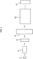
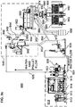
- FIG. 1 An exemplary continuous bagging system is shown schematically in Figure 1 . While the various embodiments of the present invention can involve tacky formulations, polymer-containing formulations, tacky polymer-containing formulations, and the like, for convenience, reference will be made below to tacky polymer-containing formulations. In some instances, such formulations will be referred to as polymeric materials. It should be recognized by those skilled in the art to which this disclosure pertains that the other types of formulations/materials can be interchangeably used in place of the tacky polymer-containing formulations in the description below.
- the continuous bagging process shown in Figure 1 includes a (i.e., at least one) feeding or filling section 2 that provides polymeric material (which, in exemplary embodiments, is a tacky polymer-containing material) into a mixing, melting and/or blending section 4.
- the mixing section 4 is coupled to a pelletizing section 6 which is subsequently connected via a transport system containing a pellet diverter valve(s), to a dewatering and/or drying device section 8.
- pellets Upon exiting the drying section 8, pellets are led to a pellet diverting section 10. The pellets ultimately are fed into bagging device section 12.
- An exemplary process for continuously bagging the tacky polymer-containing material generally includes feeding the tacky polymeric material from the feeding or filling section 2 to the mixing, melting, and/or blending section 4. Next, the tacky polymeric material is mixed, melted, and/or blended. This step can include extruding the tacky polymeric material.
- a further processing step includes pelletizing the material (i.e., in pelletizing section 6). After pelletization, the pellets are sent to a dewatering and/or drying device 8, via a transport system, where they are dried or dewatered. Upon drying, the pellets exit drying section 8 and enter pellet diverting section 10. Finally, the dried and diverted pellets are sent to the bagging section 12, where they are packaged for subsequent use.
- the feeding or filling section 2 and the mixing, melting and/or blending section 4 can make use of any equipment or methods known by those skilled in the art to which this disclosure pertains.
- International Patent Application Publication Nos. WO 2007/123931 and WO 2007/064580 describe the use of such systems in greater detail.
- any reference to underwater pelletizers, centrifugal dryers, and bagging machines is intended to include other types of pelletizers, dryers and bagging machines, respectively, whether used as substitutes for, or in conjunction with, those items described herein. It will be clear to those skilled in the art to which this disclosure pertains as to how such other components and process steps can be substituted for those described herein without undue efforts.
- pelletizing section 6 fittingly attached to, and just downstream of, the polymer diverter valve(s) of the mixing, melting and/or blending section 4 is pelletizing section 6.
- pelletizers that can be used in the systems and processes described herein include prillers, roto-formers, hot face pelletizers, strand pelletizers, water-ring pelletizers, and underwater pelletizers.
- a bypass loop (not shown) can be used as part of pelletizing section 6.
- Transportation fluid can be obtained from a reservoir (not shown) or other sources, and is transported toward a transport fluid box or waterbox (not shown) a through pump (not shown) that can be of a design and/or configuration to provide sufficient fluid flow into and through an optional heat exchanger (not shown) and a transport pipe to and into the bypass loop.
- the heat exchanger similarly can be of a design of suitable capacity to maintain the temperature of the transport fluid at a level appropriately suitable to maintain the temperature of the pellets being formed such that pellet geometry, throughput, and pellet quality are satisfactory without tailing, and where wrap-around of molten material on the cutter or cutting face, agglomeration of pellets, cavitation, and/or accumulation of pellets in the transport fluid box or waterbox are maximally avoided.
- the temperature, flow rate, and the composition of the transport fluid will vary with the material or formulation being processed.
- Transport medium/fluid temperatures are preferably maintained at least approximately 20°C below the melting temperature of the polymer.
- the transport medium/fluid is generally maintained at a temperature between approximately 30°C to approximately 250°C below the melt temperature of the polymer, which will often be below 10°C so as to minimize adhesion of the pellets to any surfaces of the components of the system and/or agglomeration of the pellets to one another.
- the transport fluid temperature is maintained between approximately -100°C to approximately 90°C, and also can be maintained between approximately -50°C to approximately 40°C, and can even be maintained between approximately -20°C to approximately 10°C.
- the transport fluid/medium can be water, an alcohol (including mono-hydroxy alcohols, diols, triols, and higher order alcohols), and/or another liquid that has a freezing point below that which is desired for use during the processing.
- an alcohol including mono-hydroxy alcohols, diols, triols, and higher order alcohols
- another liquid that has a freezing point below that which is desired for use during the processing.
- Mixtures of different transport fluids can also be used.
- a mixture of water and a glycol can be used as the transport fluid.
- processing aids can be accommodated in the transport fluid.
- These optional additives can be used to depress the freezing point of the transport fluid so as to extend the range of temperatures that a particular transport fluid composition can be used.
- U.S. Patent Nos. 6,120,899 , 6,238,732 , 5,869,555 , and 5,942,569 ; and International Patent Application Publication No. WO 2007/0103509 describe the use of different transport fluids in conjunction with some of these additives in greater detail.
- Piping, valving, and bypass components should be of suitable construction to withstand the temperature, chemical composition, abrasivity, corrosivity, and/or any pressure requisite to the proper transport of the pellet-transport fluid mixture. Any pressure required by the system is determined by the vertical and/or horizontal transport distance, pressure level needed to suppress unwanted volatilization of components or premature expansion, pellet-transport fluid slurry flow through valving, coarse screening, ancillary process and/or monitoring equipment.
- Pellet-to-transport fluid ratios should similarly be of varying proportions to be satisfactorily effective in eliminating or alleviating the above-mentioned complicating circumstances (e.g., pellet accumulation, flow blockage or obstruction, and agglomeration).
- Piping diameter and distances required are determined by the material throughput, thus the flow rate and pellet-to-transport fluid ratio, and time required to achieve an appropriate level of cooling and/or solidification of the pellets to avoid undesirable volatilization and/or premature expansion.
- increasing the piping diameter and/or distance between the pelletizer to the dryer is one mechanism to provide additional cooling to the pellets.
- Valving, gauges, or other processing and monitoring equipment should be of sufficient flow and pressure rating as well as of sufficient diameter to avoid undue blockage, obstruction or otherwise alter the process, leading to additional and undesirable pressure generation or process occlusion.
- the transport fluid and optional additive compositions should be compatible with the components of the pellet formulation and optionally can be readily absorbed into or adsorbed onto the components in that formulation.. Excess transport fluid and/or additives should be readily removable from the pellets by such methods as rinsing, aspiration, evaporation, dewatering, solvent removal, filtration, or similar techniques as understood by those skilled in the art.
- pelletization equipment used in pelletizing section 6 to reduce abrasion, erosion, corrosion, wear, and undesirable adhesion and stricture.
- the pelletization equipment can be nitrided, carbonitrided, metallized by sintering, and/or electrolytically plated.
- Other surface treatments for improvement of surface properties, enhancement of corrosion and abrasion resistance, improvement of wear, and/or reduction of clumping, agglomeration, and/or stricture also can be used on the pelletization equipment of pelletizing section 6. It should be noted that such coatings also can be applied to the various components of the drying, transportation, and bagging sections of the systems and processes disclosed herein.
- the transport medium transports the pellets to dewatering and/or drying section 8.
- the other types of equipment that can be in dewatering and/or drying section 8 of the systems and processes described herein include one or more of a centrifugal dryer, fluidized bed dryer, tumble dryer, and/or desiccant dryer.
- This section is designed to provide a controlled level of moisture for materials such as, but not limited to, flakes, globules, spheres, cylinders, or other geometric shapes. This can be achieved by, but is not limited to, filtration, vibratory filtration, centrifugal drying, forced or heated air convection, rotational drying, vacuum drying, or a fluidized bed.
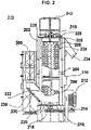
- a centrifugal dryer An exemplary centrifugal dryer 200 is illustrated in Figure 2 .
- the underwater pelletizer of section 6, and optionally other upstream processes, are coupled to dryer 200 by way of transportation pipe 302, which is shown in Figure 3 .
- Transportation pipe 302 can be connected to both pelletization section 6 and agglomerate catcher 300.
- Agglomerate catcher 300 in Figure 3 is considered to be part of centrifugal dryer 200 shown in Figure 2 .
- Transportation pipe 302 discharges the pellets and fluid slurry (or concentrated slurry) into agglomerate catcher 300, which then catches, removes and discharges pellet agglomerates through a discharge chute 304.
- Agglomerate catcher 300 includes an angled round bar grid, perforated plate, or screen 306 that permits passage of fluid and pellets but collects adhered, clumped, or otherwise agglomerated pellets and directs them toward the discharge chute 304.
- the pellets and fluid slurry then optionally, but preferably, pass into a dewatering unit 400, which is shown in Figure 2 but is detailed in Figure 4 , by way of feed chute 308, which is shown in Figure 3 .
- Dewatering unit 400 includes at least one vertical or horizontal foraminous membrane screen 402 containing one or more baffles 404 and/or an inclined foraminous membrane screen 406 that enables fluid to pass downwardly into a fines removal screen (not shown) and therethrough to a reservoir (not shown).
- Dewatering unit 400 can be attached to agglomerate catcher 300 in a number of ways, but is preferably fixedly attached to the end of feed chute 308. The pellets are then discharged from dewatering unit 400 into the lower end of the centrifugal dryer 200 by way of pellet inlet chute 236, as shown in Figure 2 .
- Pellet inlet chute 236 connects to the end of dewatering unit 400. It can be fixedly attached or detachable. While pellet inlet chute 236 may have any shape (e.g., square, rectangular, triangular, round, elliptical, or the like), it is preferably square-shaped.
- one or more walls 238 of pellet inlet chute 236 can be of solid or perforated construction. In one embodiment, the walls 238 are made partially of solid construction and partially of perforated construction. In another embodiment, the walls 238 of pellet inlet chute 236 are of solid construction.
- dryer 200 includes, but is not limited to, a generally square-shaped housing 202 having a vertically oriented generally cylindrical screen 204 mounted on a cylindrical screen support 206 at the base of the screen 204, and a cylindrical screen support 208 at the top of the screen.
- the screen 204 is thus positioned concentrically within the housing 202 in radially spaced relation from the inside wall of the housing.
- a solid screen (e.g., non-perforated sheet metal) (not shown) is also included at the bottom of the dryer 200.
- a solid screen can provide additional cooling and friction reducing mechanisms for the pellets because it allows for the transport fluid to remain on its surface, thereby providing additional time during which the pellets can remain in contact with the colder transport fluid.
- a vertical rotor 210 is mounted for rotation within the screen 204 and is rotatably driven by a motor 212 that can be mounted at and/or connected to the base of the dryer or at the top of the dryer and is preferably mounted at and or connected to the base of dryer 200.
- the motor 212 is connected to the rotor 210 by a drive pulley 214 and through a bearing 216 connected with the lower end of the housing.
- the interior dryer bottom 218 supports the rotor 210 and guide the rotational movement of the lower end of the rotor.
- Pellet inlet chute 236 is in communication with the lower end of the screen 204 and rotor 210 through the lower screen support section 220 at connection 222, and the upper end of the housing and rotor is in communication with pellet exit chute 234, through a connection (not shown) in the upper screen support section 208 at the upper end of the housing.
- the optional self-cleaning structure of the dryer 200 includes a plurality of spray nozzles or spray head assemblies 224 supported between the interior of the housing 202 and the exterior of the screen 204 as illustrated in Figure 2 .
- Spray head assemblies 224 are optionally placed in agglomerate catcher 300 (shown in Figures 2 and 3 ).
- Figures 2 and 3 additionally illustrate an exemplary placement of spray head assembly 224.
- the spray head assembly 224 of Figure 2 is supported at the end of spray pipes 226 extending upwardly through top plate 228 at the upper end of the housing with the upper ends (not shown) of the spray pipes 226 being exposed.
- Hoses or lines feed high pressure fluid (e.g., water) at a flow rate of at least approximately 40 gallons per minute (gpm), and preferably about 60 gpm to about 80 gpm, and more preferably at approximately 80 gpm or higher to the spray nozzles 224.
- the hoses can optionally feed off a single manifold (not shown) mounted on the dryer 200.
- a counter flow of air may be directed through a portion of the dryer 200 to help contain moisture within the dryer.
- a blower may suction air out of the dryer 200 through an opening 240.
- the air may enter the dryer 200 through one or more air vents 242 located at the top of the dryer 200 and/or through the pellet exit chute 234.
- the air vents 242 may filter the incoming air to prevent unwanted objects or particles from entering the dryer 200.
- the opening 240 may be closed and a blower may be housed within the dryer 200 and configured to draw air in from the air vents 242 and/or the pellet exit chute 234.
- rotor assemblies and lifter configurations can be used. These include, but are not limited to, segmented rotor assemblies, solid rotor assemblies, and the like.
- pellets exit centrifugal dryer 200 at its upper end they are sent, via piping, to a diverter valve.
- a diverter valve (not shown) is coupled to pellet exit chute for the purpose of diverting pellets from continuing onward to pellet diverter section 10 and bagging section 12. Should there be problems with machinery in pellet diverter section 10 and/or bagging section 12, should the pelletized material not meet specifications, or should there be any other reason why an operator does not want the pelletized material to continue on to any further processing, the operator can use the diverter valve to divert the pellets from further processing.
- FIG. 5a and 5c An exemplary pellet diverter valve, in accordance with some embodiments of the present invention, is illustrated in Figures 5a and 5c .
- Pellet diverter valve 500 was developed, in particular, to overcome the many problems associated with pelletizing and drying tacky polymeric materials.
- Figure 5b illustrates a prior art pellet diverter valve 501.
- prior art pellet diverter valve(s) 501 was not suitable to efficiently and reliably divert pellets during operating conditions, owing to the angle of pellet diverter plate 503 in relation to the incoming pellets.
- tacky pellets During operation of prior art pellet diverter valve 501, tacky pellets would hit diverter plate 503 with such velocity as to cause them to adhere and remain to the diverter plate 503. Subsequently, additional tacky pellets would continue to accumulate, causing a back-up in pellet exit chute 234 (shown in Figure 2 ) and eventually requiring shut-down of the system.
- pellet diverter valve(s) 500 of the present invention has been designed specifically for operation with tacky polymeric materials. Again, other polymeric materials also can be processed (i.e., diverted) using the pellet diverter valve 500.
- pellets enter pellet diverter valve(s) 500 at inlet 502 which is directly coupled or indirectly coupled (i.e., via an intermediate device) to pellet exit chute 234.
- pellet diverter valve 500 is detachably connected to pellet exit chute 234 via an extension pipe.
- the specific outlet through which the pellets will flow depends on the position of diverter flap 508.
- the position of diverter flap 508 can be controlled by hand or, preferably, by a controller (e.g., a PLC) (not shown).
- Movement of diverter flap 508 can be accomplished in a variety of ways including one or more of manually, pneumatically, electronically, automatically, or hydraulically; and the diverter flap 508 can optionally be controlled by a PLC.
- diverter flap 508 is controlled by pneumatic actuator 514 that is operated by an electronically controlled solenoid valve 516, which is controlled by a PLC.
- the solenoid valve(s) can include needle valves (not shown) that can be used to control the diverter flap 508 speed.
- the needle valves minimize the possibility of trapping a pellet between the diverter flap 508 and the interior walls of the pellet diverter valve(s) 500.
- the needle valves reduce the effects of the impact of the diverter flap 508 against these walls, therefore decreasing wear and increasing the longevity of the pellet divert valve(s) 500.
- Wall plate 518 can be detachable, so as to allow easy access to the inner mechanisms of pellet diverter 500.
- the detachability of wall plate 518 enables operators to inspect, clean, and/or repair any of the inside surfaces of pellet diverter valve(s) 500 with minimum down time.
- Detachable wall plate 518 can be made from a metal or alloy (e.g., stainless steel).
- detachable wall plate 518 can be made from a transparent material that will allow an operator to continuously monitor and observe the conditions (e.g., the flow of pellets) within the pellet diverter valve(s) 500. It should be recognized that detachable wall plate 518 can be disposed on any side wall of the pellet diverter valve(s) 500.
- the detachable wall plate 518, or another portion of the inside or outside of pellet diverter valve 500 can be equipped with an optional light source, such as a strobe light, to illuminate the interior of the pellet diverter valve 500 and/or a video camera so as to allow the operator(s) to view the interior of pellet diverter valve 500 to monitor for problems.
- an optional light source such as a strobe light
- pellet diverter valve 500 can vary based on the capacity of the equipment used in the process, the scale of the particular production run, and other like factors. Further, the pellet diverter valve(s) 500 can be formed from any material that can withstand the conditions to which it will be exposed (e.g., velocity of the pellets impinging on its interior surfaces, temperature of the pellets, and the like). In exemplary embodiments, the pellet diverter valve(s) 500 is formed from stainless steel.
- the pellet diverter valve(s) 500 generally can have an inverted "Y" shaped design. This design incorporates an angle of repose that reduces and/or eliminates the problem of pellets accumulating on diverter flap 508.
- Dotted line 520 runs through the middle of pellet diverter inlet 502 and is the axis upon which the following angles will be based.
- Angles 522 and 524 independently, can range from about 0° to about 90°, preferably from about 15° to about 60°, more preferably from about 25° to about 45°, and are most preferably about 30°.
- pellet diverter valve(s) 500 surface coatings can be applied to all internal surfaces that may come into contact with the pellets to reduce and/or eliminate corrosion, erosion, and/or adherence.
- coatings are described hereinabove. Additional examples of such coatings are provided in commonly-assigned U.S. Patent Application Serial No. 11/932,067 , which is incorporated herein by reference as if fully set forth below.
- the pellets may be sufficiently tacky to warrant a powder coating. In other instances a powder coating on the pellets may be desired.
- the powder coating can be applied to the pellets upon exiting of the dryer from exit chute 234 and before entry into the pellet diverter valve(s) 500. This can be accomplished by coupling a feeder or feeders (not shown) such as a volumetric and/or gravimetric type feeder that supplies the powder to the exit chute 234 or the piping between exit chute 234 and the diverter valve(s) (not shown).
- the feeder distributes the powder to the pellets as they traverse the exit chute 234 or the piping between exit chute 234 and the diverter valve (not shown). This pellet diverter valve would most preferably be located immediately after the feeder or feeders.
- Bagging section 12 can incorporate one or more bagging machines to package the pellets.
- bagging section 12 employs two separate bagging machines.
- pellet diverter valves could be used downstream of the pellet diverter valve described above.
- additional pellet diverter valves could be used downstream of the pellet diverter valve described above.
- a series of three pellet diverter valves can be daisy-chained to produce four outlets for the initial inlet. These four outlets could feed up to four separate bagging machines.
- seven pellet diverter valves can be daisy-chained to produce eight outlets for the initial inlet. These eight outlets could feed up to eight separate bagging machines. This daisy-chaining concept can, in theory, be extended infinitely if the volume or production rate of pellets demanded it.
- Pellet diverter valve outlets 504 and 506 can have different dimensions if desired. Preferably, they are of the same dimension so that the distance the pellets must travel upon entering pellet diverter valve 500 to a respective bagging machine is the same.
- outlets 504 and 506 can be detachably coupled (either directly or indirectly) to their respective bagging machines. In some embodiments, there may be a gap between outlets 504 and 506 and their respective bagging machines where the pellets can free flow from the outlets 504 and 506, through the gap, and into the respective bagging machine.
- the forming tube which is shown in Figure 6 and designated by reference number 602, serves to funnel the pellets into a bag, as well as to hold the bag open for the entry of the pellets.
- Forming tube 602 can be surface treated to reduce and/or eliminate corrosion, erosion, and/or adherence as described hereinabove for the various other components of the processes and systems of the present invention.
- a single PLC can control pellet diverter valve(s) 500 and each of the bagging machines (not shown).
- the PLC can be capable of operating pellet diverter valve(s) 500 so that diverter flap 508 stays in position 510 or 512 for equivalent or different time lengths.
- the PLC can allow for diverter flap 508 to stay in either position 510 or 512 longer than the other of position 512 or 510, thus allowing one bagging machine for example to produce one-pound bags while the other bagging machine produces two-pound bags.
- the PLC can control each of these components as well.
- one PLC can control each of the components of the processes and systems through the diverter valve(s), while the bagging section 12 has one PLC to control all of the bagging machines. It is also possible for each bagging machine in bagging section 12 to have a separate PLC instead of one PLC for all of the bagging machines. In some situations, separate PLCs can be used in conjunction to control the bagging step of the processes and systems. For example, one PLC can control when individual bags are prepared by the bagging machines, while another PLC can control other parameters of the bagging step (e.g., how large the bag must be, when and how long the seal should be applied, temperature of the seal, and the like).
- a scale can be, and most preferably is, installed downstream of the bagging units.
- the scale can be used to confirm the final weight of each bag and/or take the average of one or more bags and relay the information back to the PLC to make adjustments to the timing of the movement of the diverter flap 508.
- the scale will take the average weight of two or more bags and relay the information back to the PLC.
- the scales can relay such information back to the PLC so that it can make an adjustment to diverter flap's 508 timing.
- the PLC would speed up diverter flap 508 so that the bags would be open to the flow of pellets for less time, decreasing their total amount of pellets provided to the bag and thus arriving at or closer to the desired weight to offset the previous error in weight.
- the scale used with the present invention optionally has the ability to be programmed to determine which bag came from which bagger. This option allows the scale to relay to the PLC exactly which bagger is producing bags below or above the desired weight.
- the PLC will automatically trigger an alarm system to alert the operator(s) when adjustments are being made to offset the error in reproducibility yet are not correcting the error.
- the bagging machines optionally can be equipped with the vacuum capabilities to evacuate air from the bags.
- the vacuum capability allows removal of countercurrent air so as to gently remove air from the bags after the pellets have been placed inside, but before the bag is sealed, and to remove undesirable materials such as excess powder, moisture, dust, and other fragments.
- Excess powder, dust, and other fragments can collect on the interior and exterior surfaces of the bags, and can create problems during sealing.
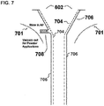
- the vacuum can be pulled from various locations in bagging section 12. Most preferably the vacuum is pulled from under the forming collar 701 out of forming tube 602 (shown in Figure 7 ), therefore drawing countercurrent air from the forming tube. The amount of vacuum pulled is adjustable and the timing of such is optionally adjustable or continuous. When powder applications are involved, a vacuum will most preferably be used continuously.
- the double walled construction illustrated in Figure 7 of forming tube 602 aids in dissipating heat given off from the sealing mechanisms and acts as a thermal barrier to minimize condensation buildup.
- Interior walls 704 are most preferably coated to prevent adherence, corrosion, and abrasion since they come into contact with the pelletized materials.
- the vacuum capabilities previously mentioned also benefit from the double walled construction of forming tube 602.
- the exterior walls of the forming tube 602 are designated by number 706.
- the inlet/outlet port 708 of forming tube 602 can be located at various positions along the exterior wall 706 of forming tube 602 and is most preferably located in the upper region of forming tube 602. It is possible to vacuum air and/or particles from forming tube 602 (indicated by the arrow in Figure 7 ), but also to blow air into forming tube 602 (indicated by an arrow). This may be desirable when the pellets begin to adhere to each other, to the equipment, or when cooling of pelletized material and/or equipment is desired.
- the film Prior to the film being formed into a bag, the film optionally can be perforated. By creating small perforations in the film, air and moisture can escape the bag. This feature is of great importance as the presence of even a small amount of moisture in the bag can be problematic in later processing of the pellet (e.g., during the melting of the bagged material in a melting pot).
- the film may be perforated at any time, but is preferably perforated just before it passes over forming collar 701.
- the number of perforations on each bag can vary. Generally speaking, the larger the bag the more perforations are desired. For example, in certain exemplary embodiments, there are about 64 perforations for every about 9.25 inches of film. Thus a one-pound bag that measures about 9.25 inches in length would have about 64 perforations.
- the size of the perforations can be of various diameters, but are preferably less than about 0.04 inches, and most preferably less than about 0.024 inches in diameter.
- the film can be perforated in various ways known to those skilled in the art.
- the film can be perforated by a roller containing a plurality of sharp points that perforate the film as the film rolls across rollers and makes its way from the roll of film to forming collar 701.
- Figure 6 illustrates a portion of the bagging machine(s) of bagging section 12.
- the bagging machine can be any type of bagging machine known to those skilled in the art to which this disclosure pertains.
- the bagging machine is a so-called "vertical form, fill, and seal" bagging machine.
- Solid line 610 represents the bottom of bagging material 608, which is created by a suitable horizontal sealing mechanism (not shown).
- the seal 610 can be created using any known sealing means, but is preferably created by fusing the bagging material 608 unto itself with a horizontal heating element.
- Dotted line 612 represents the top of bag 614, and what will be the bottom of a subsequent bag in the production process.
- the seal at dotted line 612 can be created by the same process described above for solid line 610.
- the bagging material 608 can be of any material that is suitable for holding the pellets. It is preferably made of a composition that is capable of being melted with the pellets and blendable into the melted pellet composition, such as those commercially available under the names Petrothane 421 and Lacquene.
- the composition and thickness of bagging material 608 is chosen so as not to adversely affect the desired properties of the composition of the pellets when blended into same.
- the melting temperature of the bagging material 608 should be sufficiently close to, and preferably below, that of the composition of the pellets. Otherwise, when the pellets are melted, the bagging material 608 will coagulate and could float and/or cause blockages in application equipment.
- the thickness of the bagging material 608 can be about 12.0 mil (i.e., one mil is equal to 0.001 inches and 0.025 millimeters) to about 0.5 mil, preferably from about 6.0 mil to about 0.7 mil, more preferably from about 4.5 mil to about 0.75 mil, and most preferably from about 2.0 mil to about 0.8 mil, so as to minimize the amount of bagging material 608 in the total blend or melted composition (comprising the bagging material and the pellets).
- the formulation of the bagging material 608 can include various additives (e.g., anti-foaming agents, antioxidants, stabilizers, and the like) in its formulation so as to facilitate and enhance the processing of the blend or melted composition.
- FIG 8a shows an embodiment of a continuous bagging system 800 configured to continuously bag pellets while drying the pellets better than existing systems.
- the continuous bagging system 800 may include a melt line 810, a pelletizer 820, a tempered water system (“TWS”) 830, a drying section 840, a multi-port valve 860, and a bagging assembly 870.
- TWS tempered water system
- the melt line 810 may include a melt pump 812, a melt filter 813, a melt tempering unit 814, and a polymer diverter valve 815, and may be part of the mixing section 4 described with respect to Figure 1 and in more detail in International Patent Application Publication Nos. WO 2007/123931 and WO 2007/064580 .
- an extruder and/or a booster pump may be positioned upstream of the melt line 810.
- the melt pump 812 and melt filter 813 may receive and filter a tacky and/or polymeric material before passing it on to the melt tempering unit 814.
- the melt filter 813 may include screens to prevent paper, rocks, and other undesired materials that may have been accidentally dropped into the tacky and/or polymeric material from being directed to the pelletizer 820, thereby helping the tacky and/or polymeric material to keep its desired properties and protecting the components of the continuous bagging system 800.
- the melt tempering unit 814 may receive the tacky and/or polymeric material before directing it to the polymer diverter valve 815. In some embodiments, the melt tempering unit 814 may re-melt the tacky and/or polymeric material.
- the polymer diverter valve 815 may divert the tacky and/or polymeric material to the floor or to the cutter of the pelletizer 820.
- the tacky and/or polymeric material may be directed to a drum for an alternative use or back upstream of the melt pump 812.
- the polymer diverter valve 815 may prevent an undesired material from damaging the pelletizer 820 or may allow a user to confirm the material's properties before pelletizing it.
- the pelletizer 820 may cut the melted tacky and/or polymeric material into pellets and, as the pellets are cut, they may be directed towards the drying section 840.
- the water box bypass assembly 822 may receive a flow of fluid (e.g., water) that runs from the TWS 830 via a conduit 824, and through the pelletizer 820. The fluid may cool the pellets as they are cut and transport them via a conduit 826 to the drying section 840.
- a flow of fluid e.g., water
- the TWS 830 may continue to cycle water through the continuous bagging system 800, and the water box bypass assembly 822 allows water to flow around the cutting chamber of the pelletizer 820 such that water may flow in a continuous loop regardless of whether the pelletizer 820 is in operation.
- any transport fluid can be used in the continuous bagging system 800, as disclosed herein and in U.S. Patent Pub. No. 2012/0280419 to Martin et al. (for example, at paragraphs [0293]-[0296] and U.S. Patent No. 8,080,196 to Martin et al. (for example, at Col. 33, 11. 47-65 and Col. 20, 11. 3-51).
- the pelletizer 820 may be similar to the pelletizing section 6 as described with respect to Figure 1 .
- the pellets may flow into the drying section 840 via a conduit 826.
- the drying section 840 may include a dryer 842, a pellet exit chute 844, a blower 846, an intake conduit 848, and a pellet diverter valve 850, and may be similar to the drying section 8 as described with respect to Figure 1 .
- the dryer 842 may defluidize (i.e., separate and/or remove at least a portion of moisture from) or otherwise dry the pellets.
- the dryer 842 may be a centrifugal dryer and be similar to the dryer 200 as described with respect to Figures 2 to 4 .
- the dryer 842 may dry the pellets as they pass through it, and direct the pellets to exit via the pellet exit chute 844 or pellet outlet.
- the dryer 842 may collect and direct moisture separated from the pellets to the TWS 830 via a conduit 832.
- the pellets may be directed to a conduit 852 for disposal or inspection by the pellet diverter valve 850.
- the pellet diverter valve 850 may instead direct the pellets towards the multi-port valve 860 and bagging assembly 870.
- the multi-port valve 860 may include an inlet 862 and a plurality of outlets 864, and may be similar to the pellet diverting section 10 as described with respect to Figure 1 .
- the multi-port valve 860 may be the valve described in U.S. Patent No. 8,863,931 , which is incorporated herein.
- the multi-port valve 860 may be a flapper port valve or valves that alternatingly diverts a portion of the pellets to one of the outlets 864.
- the multi-port valve 860 may receive pellets at the inlet 862 and divert pellets to one or more of the outlets 864.
- the bagging assembly 870 may include a plurality of bagging units 872, and may be similar to the bagging device section 12 as described with respect to Figures 1 and 6 to 7 .
- Each bagging unit 872 may be associated with one or more outlets 864.
- each bagging unit 872 may be positioned under one or more outlets 864 to allow for continuous bagging of the pellets.
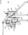
- FIG 8b shows a detailed schematic view of an embodiment of the drying section 840.
- the pellets may enter the dryer 842 as described with respect to Figures 2 to 4 , and be mechanically driven by a rotor disposed within the dryer 842. As shown, the pellets may flow in the direction of a pellet flow 801 from the bottom portion of the dryer 842 towards a pellet outlet at the top portion of the dryer 842 and into a pellet exit chute 844.
- one or more blowers 843 may be housed within the dryer 842 and configured to direct a counter flow of air 803 at least partially opposite the pellet flow 801.
- the blower 843 may draw air in from an air inlet vent 845 located at the top of the dryer 842 and/or from the pellet exit chute 844, and direct air out an air outlet vent 847.
- one or more blowers may be positioned outside of the dryer 842 and configured to blow or suction the counter flow of air 803 at least partially against the pellet flow 801.
- the flow rate of the counter flow of air 803 through the dryer 842 may be limited to a level that does not prevent the pellets from exiting the dryer 842.
- the rotor may mechanically drive the pellets along a portion of the pellet flow 801 within the dryer 842 and direct the pellets into the pellet exit chute 844.
- the counter flow of air 803 may be limited such that it does not direct pellets entering the pellet exit chute 844 back into the dryer 842, thereby overcoming the force from the rotor at the pellet exit chute 844. If the counter flow of air 803 is not limited, the pellets may adhere to one another or to surfaces of the dryer, which could clog or jam the continuous bagging system 800.
- the counter flow of air 803 may be increased to a flow rate level that would, on its own, prevent the pellets from exiting the dryer 842.
- a blower 846 may direct a transport flow of air 805 to remove pellets from the dryer 842 into the pellet exit chute 844.
- the transport flow of air 805 may help prevent the pellets from sticking together as they exit, or attempt to exit, the dryer 842, while allowing for an increased flow rate of the counter flow of air 803, and thus, increased drying of the pellets and/or preventing excess moisture from escaping the dryer 842.
- the flow rate of the counter flow of air 803 may still be limited such that it does not overcome the transport flow of air 805 or the rotor.
- the counter flow of air 803 may be configured to overcome the force of the rotor only at the pellet exit chute 844 (such that the rotor still mechanically drives the pellets along the rest of the pellet flow path 801), but limited such that the transport flow of air 805 may pull the pellets into the pellet exit chute 844. It is contemplated that the air flows within the dryer 842, along with the mechanical force of the rotor, may be in balance relative to one another and not shift the problem from the pellet exit chute 844 to a conduit 854 or another point downstream.
- the blower 846 may direct a drying flow of air 807 in a direction at least partially opposite the pellet flow path for at least a portion of the path from the dryer 842 to the multi-port valve 860 (e.g., the conduit 854) to further dry the pellets.
- the blower 846 may suction the drying flow of air 807 to further dry the pellets regardless of the flow rate of the counter flow of air 803 through the dryer 842.
- the blower 846 may limit suction of the drying flow of air 807 to a level that does not overcome the flow of the pellets down towards the multi-port valve 860.
- the flow rate of the drying flow of air 807 may depend on a number of factors including, for example, the angle, length, and size of the pellet exit chute 844 and/or the conduit 854, and the pellet size, shape, and tackiness.
- the pellet exit chute 844 and/or the conduit 854 may extend downwardly from the dryer 842 at an angle at least 45° from the horizontal plane.
- the flows of air 803 and 807 opposite the pellet flow 801 may be more effective at removing moisture from the pellets than other methods.
- blower 846 and intake conduit 848 may be disposed upstream or downstream of the pellet diverter valve 850. Further, the intake conduit 848 may extend from the pellet exit chute 844 or the conduit 854 at any angle and position. In some embodiments, the intake conduit 848 may extend upwardly from the top portion or side(s) of the conduit 854, decreasing the likelihood that pellets would be suctioned into the blower 846 or stuck onto a screen preventing the pellets from being suctioned into the blower 846.
- the intake conduit 848 is shown extending vertically from the conduit 854, it is contemplated that the intake conduit 848 may extend from the conduit 854 at any angle (e.g., 30°, 90°, 120°, etc.) to fit the layout of the continuous bagging system 800 and/or to decrease work on the blower 846 by increasing or decreasing the angled corner at which the flows of air 805 and 807 must pass around.
- the intake conduit 848 may extend downwardly from the bottom of sides of the conduit 854, and a screen (not shown) may cover the entrance into the intake conduit 848 to prevent pellets from being suctioned into the blower 846.
- Each of the conduits and chutes transporting the pellets may be substantially straight in some embodiments to prevent the pellets from sticking together or to the conduits.
- Figure 9a shows an embodiment of a continuous bagging system 900, which may include a melt line910, a pelletizer 920, a tempered water system ("TWS") 930, a drying section 940, a multi-port valve 980, and a bagging assembly 990. Operation of the continuous bagging system 900 may be similar to that of continuous bagging system 800 with the addition of a conditioning unit 960 disposed within the drying section 940.
- TWS tempered water system
- the melt line 910 and its material pump 912, melt filter 913, melt tempering unit 914, and polymer diverter valve 915, the pelletizer 920 and its water box bypass assembly 922, conduits 924, 926, and 932, the TWS 930, a dryer 942, a pellet exit chute 944, a blower 946, an intake conduit 948, a pellet diverter valve 950 and its conduit 952 and conduit 954, the multi-port valve 980 and its inlet 982 and plurality of outlets 984, and the bagging assembly 990 and its bagging units 992 may be similar to the corresponding components described with respect to Figures 8a and 8b .
- Figure 9b shows a detailed schematic view of an embodiment of the drying section 940.
- the pellets may flow in the direction of a pellet flow 901 from the bottom portion of the dryer 942 towards a pellet outlet at the top portion of the dryer 942 and into the pellet exit chute 944.
- a blower 943 may be housed within or connected to the dryer 942 and configured to direct a counter flow of air 903 at least partially opposite the pellet flow 901.
- the flow rate of the counter flow of air 903 through the dryer 942 may be limited to a level that does not prevent the pellets from exiting the dryer 942 into the pellet exit chute 944.
- the counter flow of air 903 may be increased to a flow rate level that would, on its own, prevent the pellets from exiting the dryer 942.
- the blower 946 may direct a transport flow of air 905 to remove pellets from the dryer 942 into the pellet exit chute 944.
- the blower 946 may direct a drying flow of air 907 in a direction at least partially opposite the pellet flow path for at least a portion of the path from the dryer 942 to the conditioning unit 960 (e.g., conduit 954) to further dry the pellets.
- the blower 946 may suction or otherwise direct the drying flow of air 907 to further dry the pellets regardless of the flow rate of the counter flow of air 903 through the dryer 942.
- the pellet flow 901 (as driven by the rotor of the dryer 942), the counter flow of air 903, and transport flow of air 905, and the drying flow of air 907 may be balanced relative to one another as described with respect to Figure 8b .
- the pellets may pass through conduit 954 to the conditioning unit 960 for conditioning. It is contemplated that the conduit 954 may be configured to prevent the drying flow of air 907 from entering or otherwise affecting the pellet and air flows within the conditioning unit 960.
- the conditioning unit 960 may be a coater configured to coat the pellets in a powder from a powder feeder 962. The coating powder may further dry the pellets or make the pellets less likely to adhere to one another or to components of the continuous bagging system 900 prior to bagging, and may be a coating powder as previously described herein.
- the conditioning unit 960 may be a tumbler configured to further dry the pellets by rotating them through a perforated drum. As the pellets move through the conditioning unit 960, moisture may be removed from the pellets and directed to conduit 932 and/or the TWS 930 via a conduit 964. Further, fluid (e.g., water) may be collected at any component within the continuous bagging system 900 and directed back to the TWS 930 for reuse.
- fluid e.g., water
- the tumbler may be shaped and/or angled to provide a desired residence time for the pellets or to allow the pellets to sufficiently condition (e.g., warm up).
- the dried and/or coated pellets may exit the conditioning unit 960 into pellet exit chute 966 and flow into a pellet diverter valve 970.
- the pellet diverter valve 970 which may be included in any of the disclosed embodiments, may allow for the disposal of unsatisfactory product via a conduit 972. By doing so, the pellet diverter valve 970 allows for the inspection of the product immediately prior to bagging, which could help reduce waste due to clumping or undesirable levels of coating.
- the pellets exiting the pellet exit chute 966 may be transported via a conduit 974 to the multi-port valve 980, which diverts the pellets as desired to the outlets 984 for continuous bagging via the bagging assembly 990.
- FIG 10 shows an embodiment of a continuous bagging system 1000, which may include melt line 1010, a pelletizer 1020, a tempered water system ("TWS") 1030, a drying section 1040, pellet diverter valves 1050 and 1070, a multi-port valve 1080, and a bagging assembly 1090. Operation of the continuous bagging system 1000 may be similar to that of continuous bagging system 900 without the blower 946 and the intake conduit 948 within the drying section 940.
- TWS tempered water system
- the melt line 1010 and its material pump 1012, melt filter 1013, melt tempering unit 1014, and polymer diverter valve 1015, the pelletizer 1020 and its water box bypass assembly 1022, conduits 1024, 1026, and 1032, the TWS 1030, a dryer 1042, a pellet exit chute 1044, pellet diverter valves 1050 and 1070 and their conduits 1052 and 1072, a conduit 1054, the conditioning unit 1060 and its powder feeder 1062 and conduits 1064 and 1066, a conduit 1074, the multi-port valve 1080 and its inlet 1082 and plurality of outlets 1084, and the bagging assembly 1090 and its bagging units 1092 may be similar to the corresponding components described with respect to Figures 9a and 9b .
- the continuous bagging system 1000 may defluidize or otherwise dry pellets in the dryer 1042, and direct the pellets out of the pellet exit chute 1044 and into the conditioning unit 1060 for conditioning.
- the conditioning unit 1060 may be a coater configured to coat the pellets in a powder from the powder feeder 1062. The coating powder may further dry the pellets or make the pellets less likely to adhere to one another or to components of the continuous bagging system 1000 prior to bagging.
- the conditioning unit 1060 may be a tumbler configured to further dry and/or classify the pellets by rotating them through a perforated drum, as previously described with respect to Figure 9b .
- pellets move through the conditioning unit 1060 moisture may be removed from the pellets and directed to conduit 1032 and/or the TWS 1030 via a conduit 1064.
- the dried and/or coated pellets may exit the conditioning unit 1060 into pellet exit chute 1066 and flow into the pellet diverter valve 1070.
- the pellet diverter valve 1070 may allow for the disposal of unsatisfactory product via the conduit 1072. By doing so, the pellet diverter valve 1070 allows for the inspection of the product immediately prior to bagging, which could help reduce waste due to clumping or undesirable levels of coating.
- FIG 11 shows an embodiment of a continuous bagging system 1100, which may include melt line 1110, a pelletizer 1120, a tempered water system ("TWS") 1130, a drying section 1140, a pellet diverter valve 1170, a multi-port valve 1180, and a bagging assembly 1190. Operation of the continuous bagging system 1100 may be similar to that of continuous bagging system 1000 wherein the dryer 1042 is replaced with a dewatering unit 1150.
- TWS tempered water system
- melt line 1110 and its material pump 1112, melt filter 1113, melt tempering unit 1114, and polymer diverter valve 1115, the pelletizer 1120 and its water box bypass assembly 1122, conduits 1124, 1126, and 1132, the TWS 1130, the conditioning unit 1160 and its conduits 1162 and 1164, a pellet diverter valve 1170 and its conduits 1172 and 1174, the multi-port valve 1180 and its inlet 1182 and plurality of outlets 1184, and the bagging assembly 1190 and its bagging units 1192 may be similar to the corresponding components described with respect to Figure 10 .
- the continuous bagging system 1100 may dry pellets in the dewatering unit 1150, direct the pellets out of the pellet slurry outlet 1152 and into the conditioning unit 1160 for conditioning (e.g., final dewatering).
- the dewatering unit 1150 acting as a water separator/dewaterer in the continuous bagging system 1100, may remove between about 70% to about 75% of the fluid (e.g., water plus additives) from the pellets.
- the dewatering unit 1150 may be uniquely suited to defluidize or otherwise dry extremely brittle material that may not survive a centrifugal dryer.
- the dewatering unit 1150 may be stationary and house a screen at about 45° to horizontal to allow fluid to pass through downwardly while directing the pellets to one side.
- the fluid can flow through the angled screen as the angled screen directs the pellets away from the fluid and to an exit area of the dewatering unit 1150.
- the screen may be disposed at any angle. Used in this manner, the screen may be a perforated mesh screen. In one embodiment, for example, the screen may be about six inches in diameter and two feet long.
- the dewatering unit 1150 may house one or more dynamic screens, such as a rotating or vibrating screen.
- the pellets rest on the vibrating screen(s), and the vibration of the screen(s) can cause excess fluid to drain off the pellets and fall through the screen(s).
- the screens can be layered to allow smaller pellets to fall through the upper screen(s), which can have larger gaps, onto lower screen(s), which can have smaller gaps. In this manner, the screens can separate the pellets by size while drying the pellets.
- the vibration can also cause the pellets to move along the screens, while drying, to an exit area of the dewatering unit 1150.
- the dewatering unit 1150 may comprise a fines removal sieve to remove fines, or excess material, from the fluid/pellet flow. Moreover, in some embodiments, the dewatering unit 1150 may comprise forced or heated air convection systems, rotating drying systems, or a fluidized bed. In some embodiments, the dewatering unit 1150 may comprise an agglomerate catcher to remove agglomerates from the pellet flow. Alternatively, the agglomerate catcher can be separate from the dewatering unit 1150.
- a dryer 1142 similar to the dryer 1042 described with respect to Figure 10 may be included in the continuous bagging system 1100 in some embodiments.
- the conditioning unit 1160 may be a tumbler and act as a secondary dryer for the pellets.
- the conditioning unit 1160 may rotate the pellets in a perforated drum, thereby removing between about 20% to about 30% of the fluid (e.g., water plus additives) from the pellets.
- the conditioning unit 1160 may be a tumbler and act as a classifier and only allow pellets of a certain size and/or shape to pass or otherwise sort the pellets.
- one or more additional conditioning units may be included downstream of the conditioning unit 1160.
- a downstream conditioning unit may be a coater configured to coat the pellets in a powder from a powder feeder. The coating powder may further dry the pellets or make the pellets less likely to adhere to one another or to components of the continuous bagging system 1100 prior to bagging. It is contemplated that multiple conditioning units 1160 may be used to defluidize or otherwise dry and coat the pellets.
- one or more blowers and/or pellet diverter valves may be used with any of the disclosed continuous bagging systems 800, 900, 1000, and 1100.
- pellets move through the conditioning unit 1160 moisture may be removed from the pellets and directed to conduit 1132 and/or the TWS 1130 via a conduit 1162.
- the dried and/or coated pellets may exit the conditioning unit 1160 into pellet exit chute 1164 and flow into the pellet diverter valve 1170.
- the pellet diverter valve 1170 may allow for the disposal of unsatisfactory product via the conduit 1172. By doing so, the pellet diverter valve 1170 allows for the inspection of the product immediately prior to bagging, which could help reduce waste due to clumping or undesirable levels of coating.
Landscapes
- Engineering & Computer Science (AREA)
- Mechanical Engineering (AREA)
- General Engineering & Computer Science (AREA)
- Chemical & Material Sciences (AREA)
- Dispersion Chemistry (AREA)
- Life Sciences & Earth Sciences (AREA)
- Molecular Biology (AREA)
- Health & Medical Sciences (AREA)
- Microbiology (AREA)
- Processing And Handling Of Plastics And Other Materials For Molding In General (AREA)
- Drying Of Solid Materials (AREA)
- Supply Of Fluid Materials To The Packaging Location (AREA)
- Basic Packing Technique (AREA)
Claims (10)
- Procédé pour l'ensachage continu de granulés collants et/ou contenant des polymères, le procédé comprenant :l'agglomération d'une composition collante et/ou contenant des polymères dans un granulateur (820) ;la défluidisation de granulés de la composition collante et/ou contenant des polymères dans un séchoir (842), dans lequel les granulés entrent dans le séchoir (842) et sont mécaniquement entraînés par un rotor (210) disposé à l'intérieur du séchoir (842), de sorte que les granulés s'écoulent dans la direction d'un écoulement de granulés (801) à partir de la partie inférieure du séchoir (842) en direction d'une évacuation de granulés au niveau de la partie supérieure du séchoir (842) et dans une glissière de sortie de granulés (844) ;la direction, le long d'au moins une partie du trajet d'écoulement de granulés (801), d'un contre-écoulement d'air (803) à l'intérieur du séchoir (842) au moins partiellement opposé à l'écoulement de granulés avec un débit accru du contre-écoulement d'air, résultant en un séchage accru des granulés et/ou empêchant qu'une humidité excédentaire ne s'échappe du séchoir,la direction des granulés défluidisés à partir de l'évacuation de granulés du séchoir en direction d'une soupape à orifices multiples (860), dans lequel la direction des granulés en direction de la soupape à orifices multiples comprend la fourniture d'un écoulement d'air de transport (805) avec un débit suffisant pour contrebalancer le contre-écoulement d'air (803) et éloigner les granulés défluidisés de l'évacuation de granulés, et la fourniture d'un écoulement d'air séchant (807) au moins partiellement opposé à un écoulement directionnel des granulés en direction de la soupape à orifices multiples (860) ;dans lequel le séchoir est raccordé à une conduite (854) qui reçoit les granulés séchés du séchoir, la conduite comprenant une ou plusieurs soufflantes (846) qui dirigent les granulés séchés à partir d'une évacuation de granulés du séchoir vers la conduite via ledit écoulement d'air de transport (805) et dans lequel la ou les soufflantes aspirent également ledit écoulement d'air séchant (807) au moins partiellement opposé à l'écoulement directionnel des granulés en direction de la soupape à orifices multiples (860) ;la déviation continue d'une quantité spécifique des granulés à travers l'une d'une pluralité d'évacuations (984) de la soupape à orifices multiples (860) ; etl'ensachage continu des granulés au moyen d'un ensemble d'ensachage (990) situé au niveau d'une ou de plusieurs évacuations de la pluralité d'évacuations de la soupape à orifices multiples.
- Procédé pour l'ensachage continu de granulés collants et/ou contenant des polymères selon la revendication 1, dans lequel la fourniture de l'écoulement d'air séchant (804) comprend l'aspiration, par une ou plusieurs soufflantes (846) disposées entre l'évacuation de granulés et la soupape à orifices multiples (860), de l'écoulement d'air séchant, et la fourniture de l'écoulement d'air de transport (805) comprend l'aspiration, par une ou plusieurs soufflantes, de l'écoulement d'air de transport.
- Procédé pour l'ensachage continu de granulés collants et/ou contenant des polymères selon la revendication 1, dans lequel la direction des granulés à travers le séchoir comprend l'entraînement mécanique des granulés à travers le séchoir le long d'au moins une partie du trajet d'écoulement de granulés pour maîtriser le contre-écoulement d'air.
- Procédé pour l'ensachage continu de granulés collants et/ou contenant des polymères selon la revendication 3, dans lequel la fourniture du contre-écoulement d'air (803) comprend la fourniture, au moins au niveau de l'évacuation de granulés, du contre-écoulement d'air à un débit suffisant pour maîtriser l'entraînement mécanique des granulés pour empêcher que les granulés ne sortent de l'évacuation de granulés.
- Procédé pour l'ensachage continu de granulés collants et/ou contenant des polymères selon la revendication 1, dans lequel la déviation continue de la quantité spécifique de granulés par le biais d'une ou de plusieurs évacuations de la pluralité d'évacuations (984) de la soupape à orifices multiples (860) est basée sur un intervalle de temps prédéterminé qui résulte en la déviation de la quantité spécifique de granulés.
- Procédé pour l'ensachage continu de granulés collants et/ou contenant des polymères selon la revendication 1, comprenant en outre :le conditionnement des granulés défluidisés dans une unité de conditionnement (960, 1060) en aval du séchoir, dans lequel le conditionnement des granulés défluidisés comprend le séchage des granulés défluidisés et/ou l'application d'une poudre revêtant les granulés défluidisés ; etla direction des granulés à partir de l'unité de conditionnement vers la soupape à orifices multiples.
- Procédé pour l'ensachage continu de granulés collants et/ou contenant des polymères selon la revendication 6, dans lequel l'unité de conditionnement est un tambour.
- Système pour l'ensachage continu de granulés collants et/ou contenant des polymères, le système comprenant :un granulateur (820) configuré pour granuler une composition collante et/ou contenant des polymères ;un séchoir (842) configuré pour sécher des granulés de la composition collante et/ou contenant des polymères à mesure que les granulés se déplacent le long d'un trajet d'écoulement de granulés à travers le séchoir,dans lequel le séchoir (842) comprend un rotor (210) disposé à l'intérieur du séchoir (842), de sorte que les granulés s'écoulent dans la direction d'un écoulement de granulés (801) à partir de la partie inférieure du séchoir (842) en direction d'une évacuation de granulés au niveau de la partie supérieure du séchoir (842) et dans une glissière de sortie de granulés (844),une soufflante (843) pour diriger un contre-écoulement d'air (803) au moins partiellement opposé à l'écoulement de granulés (801) avec un débit accru du contre-écoulement d'air, résultant en un séchage accru des granulés et/ou empêchant qu'une humidité excédentaire ne s'échappe du séchoir, dans lequel le contre-écoulement d'air (803) présente un niveau de débit qui, seul, empêcherait que les granulés ne sortent du séchoir (842) ;une conduite (854) configurée pour recevoir les granulés séchés du séchoir, la conduite comprenant une ou plusieurs soufflantes (846) configurées pour diriger les granulés séchés à partir d'une évacuation de granulés du séchoir vers la conduite via un écoulement d'air de transport (805) ;dans lequel l'écoulement d'air de transport (805) présente un débit suffisant pour contrebalancer le contre-écoulement d'air (803) et s'écoule dans la direction d'écoulement de granulés (801) pour attirer les granulés à partir du séchoir et dans la glissière de sortie de granulés (844) et la conduite (854) ;dans lequel la ou les soufflantes (860) sont en outre configurées pour aspirer un écoulement d'air séchant (807) au moins partiellement opposé à un écoulement directionnel des granulés en direction d'une soupape à orifices multiples (860) ;dans lequel la soupape à orifices multiples (860) est configurée pour acheminer en continu un écoulement entrant des granulés, la soupape à orifices multiples ayant au moins une admission (862) pour recevoir l'écoulement entrant de granulés et une pluralité d'évacuations (864) pour distribuer un écoulement sortant des granulés ; etune pluralité d'unités d'ensachage (872) configurée pour recevoir en alternance une quantité prédéterminée de granulés à partir d'une ou de plusieurs évacuations de la pluralité d'évacuations de la soupape à orifices multiples pour permettre un ensachage continu des granulés.
- Système pour l'ensachage continu de granulés collants et/ou contenant des polymères selon la revendication 8, comprenant en outre une unité de conditionnement (960, 1060) configurée pour sécher et/ou appliquer en outre une poudre de revêtement aux granulés séchés.
- Système pour l'ensachage continu de granulés collants et/ou contenant des polymères selon la revendication 9, dans lequel l'unité de conditionnement est un tambour.
Applications Claiming Priority (2)
| Application Number | Priority Date | Filing Date | Title |
|---|---|---|---|
| US14/601,740 US9925694B2 (en) | 2009-02-24 | 2015-01-21 | Continuous bagging processes and systems |
| PCT/US2016/014214 WO2016118687A1 (fr) | 2015-01-21 | 2016-01-21 | Procédés et systèmes d'ensachage continu |
Publications (3)
| Publication Number | Publication Date |
|---|---|
| EP3247639A1 EP3247639A1 (fr) | 2017-11-29 |
| EP3247639A4 EP3247639A4 (fr) | 2018-08-22 |
| EP3247639B1 true EP3247639B1 (fr) | 2020-03-04 |
Family
ID=56417718
Family Applications (1)
| Application Number | Title | Priority Date | Filing Date |
|---|---|---|---|
| EP16740720.4A Active EP3247639B1 (fr) | 2015-01-21 | 2016-01-21 | Procédés et systèmes d'ensachage continu |
Country Status (8)
| Country | Link |
|---|---|
| EP (1) | EP3247639B1 (fr) |
| JP (1) | JP6736563B2 (fr) |
| KR (1) | KR102330520B1 (fr) |
| CN (1) | CN107428421B (fr) |
| BR (1) | BR112017015555B1 (fr) |
| MX (1) | MX2017009428A (fr) |
| WO (1) | WO2016118687A1 (fr) |
| ZA (1) | ZA201705375B (fr) |
Families Citing this family (6)
| Publication number | Priority date | Publication date | Assignee | Title |
|---|---|---|---|---|
| WO2019201721A1 (fr) * | 2018-04-20 | 2019-10-24 | Borealis Ag | Procédé de transport de particules de polyoléfine dans un système de transport de polymère |
| CN109606761A (zh) * | 2019-01-30 | 2019-04-12 | 成秀东 | 一种设有传输功能的智能化分装站 |
| CN110816913A (zh) * | 2019-12-06 | 2020-02-21 | 无锡凯锦华塑业有限公司 | 一种塑料切粒机自动包装器 |
| CN111121397B (zh) * | 2019-12-26 | 2022-07-19 | 安徽省墨凡嘉羽绒制品有限公司 | 一种羽绒制品的鹅绒防飞绒甩干装置 |
| KR102375162B1 (ko) * | 2020-03-27 | 2022-03-16 | 김용동 | 필름의 생분해성 원료 펠렛형 가공물을 제조하기 위한 시스템 및 이로부터 취득된 펠렛형 가공물의 방습용 코팅장치를 이용한 방습 방법 |
| CN112595025B (zh) * | 2020-11-20 | 2023-06-30 | 湖南开磷雁峰塔涂料有限公司 | 一种涂料制备用脱水设备 |
Family Cites Families (65)
| Publication number | Priority date | Publication date | Assignee | Title |
|---|---|---|---|---|
| DE313822C (fr) | ||||
| US36177A (en) | 1862-08-12 | Improvement in the bobbins of throstle spinning-machines | ||
| US2996308A (en) | 1958-11-10 | 1961-08-15 | Gen Motors Corp | Self-aligning suspension control arm bearing assembly |
| US3458045A (en) | 1966-08-26 | 1969-07-29 | Gala Inc | Centrifugal pellet drier |
| US3521426A (en) | 1968-02-13 | 1970-07-21 | James C H Evins | Alignment and/or packaging apparatus |
| DE1953741C3 (de) | 1969-10-24 | 1981-02-05 | Gala Industries, Inc., Eagle Rock, Va. (V.St.A.) | Vorrichtung zum Trennen von Festteilchen wie z.B. Kunststoffgranulaten und Flüssigkeit |
| US4123207A (en) | 1976-03-29 | 1978-10-31 | Gala Industries, Inc. | Underwater pelletizer and heat exchanger die plate |
| DE2819443C2 (de) | 1978-05-03 | 1986-11-20 | Gala Industries, Inc., Virginia | Rotor für einen Fliehkraftabscheider |
| US4218323A (en) | 1978-08-09 | 1980-08-19 | Gala Industries, Inc. | Pellet free rotor for centrifugal pellet dryers |
| US4251198A (en) | 1979-04-27 | 1981-02-17 | Gala Industries, Inc. | Cutter hub with replaceable knife blades for underwater pelletizer |
| JPS56149919A (en) * | 1980-04-18 | 1981-11-20 | Suupaafuan Kk | Injection feeder |
| US4447325A (en) | 1981-01-27 | 1984-05-08 | Gala Industries, Inc. | Vertical pre-dewatering screen |
| DE3234065A1 (de) | 1981-09-25 | 1983-04-14 | Dr. Rudolf Schieber Chemische Fabrik GmbH & Co KG, 7085 Bopfingen | Verfahren zur behandlung von in mischaggregaten hergestellen druckempfindlichen schmelzmassen |
| JPS59195433A (ja) | 1983-04-22 | 1984-11-06 | Shin Sumino | 篩別け装置を備えたダンプ運搬車 |
| US4565015A (en) * | 1983-07-27 | 1986-01-21 | Gala Industries, Inc. | Centrifugal pellet dryer |
| DE3327289A1 (de) | 1983-07-28 | 1985-02-07 | Gebr. Kaiser, 4150 Krefeld | Verfahren zur konfektionierung von haftschmelzklebstoffen |
| US4500271A (en) | 1983-12-06 | 1985-02-19 | Gala Industries, Inc. | Underwater pelletizer with adjustable blade assembly |
| US4621996A (en) | 1985-04-24 | 1986-11-11 | Gala Industries, Inc. | Removable die center for extrusion dies |
| US4728276A (en) | 1986-01-31 | 1988-03-01 | Gala Industries, Inc. | Underwater pelletizer |
| US4888990A (en) | 1988-05-02 | 1989-12-26 | Gala Industries, Inc. | Sight glass apparatus |
| US4896435A (en) | 1988-05-10 | 1990-01-30 | Gala Industries Inc. | Replaceable wear parts for centrifugal pellet dryers |
| US5059103A (en) | 1990-07-30 | 1991-10-22 | Gala Industries, Inc. | Underwater pelletizer |
| RU2096277C1 (ru) | 1990-08-01 | 1997-11-20 | Х.Б.Фуллер Лайсенсинг энд Файнэнсинг Инк. | Способ упаковки клеящей композиции (варианты) и упакованная клеящая композиция (варианты) |
| US5403176A (en) | 1991-02-01 | 1995-04-04 | Gala Industries, Inc. | Tapered insert die plate for underwater pelletizers |
| US5265347A (en) | 1992-09-04 | 1993-11-30 | Gala Industries, Inc. | Centrifugal pellet dryer |
| DE9320744U1 (de) | 1992-09-04 | 1995-01-19 | Gala Inc | Zentrifugaltrockner für Pellets |
| US5624688A (en) | 1995-10-12 | 1997-04-29 | Gala Industries, Inc. | Self-aligning cutter hub |
| AU719936B2 (en) | 1995-11-16 | 2000-05-18 | H.B. Fuller Company | A polymeric composition in pellet form |
| US5638606A (en) | 1996-03-06 | 1997-06-17 | Gala Industries, Inc. | Spider and lifter assembly for centrifugal pellet dryer |
| US5895617A (en) | 1996-07-31 | 1999-04-20 | The Japan Steel Works, Ltd. | Method and apparatus for transporting underwater cut pellets |
| US6332765B1 (en) | 1996-11-15 | 2001-12-25 | Gala Industries, Inc. | Cutter hub holder |
| AU1073399A (en) | 1997-10-08 | 1999-04-27 | H.B. Fuller Licensing And Financing Inc. | Hot melt adhesive pellet comprising continuous coating of pelletizing aid |
| AU6988298A (en) | 1998-06-04 | 1999-12-16 | H.B. Fuller Licensing And Financing Inc. | Aqueous laminating adhesive composition and a method of using thereof |
| US6237244B1 (en) | 1998-10-19 | 2001-05-29 | Gala Industries, Inc. | Centrifugal pellet dryer for small applications |
| WO2000034129A1 (fr) * | 1998-12-10 | 2000-06-15 | Henkel Kommanditgesellschaft Auf Atkien | Procede d'emballage d'adhesif thermofusible sensible a la pression |
| US6138375A (en) | 1999-03-01 | 2000-10-31 | Gala Industries, Inc. | Support ring for pellet dryer screen |
| US6551087B1 (en) | 1999-09-21 | 2003-04-22 | Gala Industries, Inc. | Flow guide for underwater pelletizer |
| US6807748B2 (en) | 1999-10-19 | 2004-10-26 | Gala Industries, Inc. | Centrifugal pellet dryer |
| US20020176905A1 (en) | 2001-03-22 | 2002-11-28 | Fridley Michael A. | Self-aligning cutter hub assembly |
| US6824371B2 (en) | 2001-08-02 | 2004-11-30 | Gala Industries, Inc. | Insulation plug for underwater pelletizer die face recess |
| US6739457B2 (en) | 2001-08-17 | 2004-05-25 | Gala Industries, Inc. | Deflector for centrifugal pellet dryer screen |
| US7033152B2 (en) | 2002-05-09 | 2006-04-25 | Gala Industries, Inc | Underwater pelletizer with positively controlled cutter HUB |
| US6925741B2 (en) | 2002-10-29 | 2005-08-09 | Gala Industries, Inc. | Sectioned adjustable water flow guide for pelletizer |
| US7172397B2 (en) | 2003-11-18 | 2007-02-06 | Gala Industries, Inc. | Two-piece water box assembly for pelletizer |
| US7157032B2 (en) | 2003-11-21 | 2007-01-02 | Gala Industries, Inc. | Method and apparatus for making crystalline PET pellets |
| US7318719B2 (en) | 2004-04-01 | 2008-01-15 | Gala Industries, Inc. | Steep angle cutter hub and blade assembly |
| US7024794B1 (en) | 2004-10-15 | 2006-04-11 | Gala Industries | Centrifugal pellet dryer with plastic wall panels |
| US7171762B2 (en) | 2004-10-19 | 2007-02-06 | Gala Industries, Inc. | Self-cleaning centrifugal pellet dryer and method thereof |
| US20060130353A1 (en) | 2004-12-21 | 2006-06-22 | Michael Eloo | Centrifugal pellet dryer screen |
| US7402034B2 (en) | 2005-01-25 | 2008-07-22 | Gala Industries, Inc. | Center heated die plate for underwater pelletizer |
| EP1954470B1 (fr) | 2005-11-28 | 2014-04-30 | Gala Industries, Inc. | Appareil et procede destines au traitement controle de pelletisation |
| US7267540B2 (en) | 2006-01-26 | 2007-09-11 | Gala Industries, Inc. | Steep angle cutter hub with blunt edge blades |
| WO2007103509A2 (fr) | 2006-03-09 | 2007-09-13 | Gala Industries, Inc. | Appareil et procédé de pastillage de la cire et de matériaux analogues à la cire |
| US7771635B2 (en) | 2006-04-20 | 2010-08-10 | Gala Industries, Inc. | Melt cooler and valving system for an underwater pelletizing process |
| EP2008784B1 (fr) * | 2007-06-25 | 2013-02-27 | Gala Industries, Inc. | Procédé et appareil pour produire des granules de polymère contenant des volatils et/ou un matériau générant un volatil |
| US20090110833A1 (en) | 2007-10-31 | 2009-04-30 | Gala Industries, Inc. | Method for abrasion-resistant non-stick surface treatments for pelletization and drying process equipment components |
| US8080196B2 (en) | 2008-02-12 | 2011-12-20 | Gala Industries, Inc. | Method and apparatus to achieve crystallization of polymers utilizing multiple processing systems |
| CN102333701B (zh) * | 2009-02-24 | 2014-01-15 | 戈拉工业公司 | 连续打包工艺及系统 |
| CA2752086C (fr) * | 2009-06-22 | 2017-05-16 | Gala Industries, Inc. | Systemes de pastillage, de sechage et d'ensachage en continu a rendement ameliore |
| MX2012007637A (es) * | 2009-12-31 | 2012-09-12 | Bostik Inc | Proceso para empacar resinas de poliéster adherentes. |
| US8562915B2 (en) * | 2010-01-14 | 2013-10-22 | Exxonmobil Chemical Patents Inc. | Processes and apparatus for polymer finishing and packaging |
| DE102010032350A1 (de) | 2010-07-27 | 2012-02-02 | Automatic Plastics Machinery Gmbh | Vorrichtung zur Trocknung von Granulatkörnern |
| US20120280419A1 (en) | 2011-05-03 | 2012-11-08 | Gala Industries, Inc. | Method and apparatus for fluidic pelletization, transport, and processing of materials |
| KR20160007673A (ko) | 2011-05-29 | 2016-01-20 | 갈라 인더스트리스 인코포레이티드 | 재료의 분포를 제어하는 밸브 장치, 시스템 및 방법 |
| US20140250709A1 (en) | 2013-03-05 | 2014-09-11 | Gala Industries, Inc. | Dryers in series with improved throughput |
-
2016
- 2016-01-21 JP JP2017538311A patent/JP6736563B2/ja active Active
- 2016-01-21 WO PCT/US2016/014214 patent/WO2016118687A1/fr active Application Filing
- 2016-01-21 BR BR112017015555-9A patent/BR112017015555B1/pt active IP Right Grant
- 2016-01-21 CN CN201680015828.1A patent/CN107428421B/zh active Active
- 2016-01-21 MX MX2017009428A patent/MX2017009428A/es unknown
- 2016-01-21 KR KR1020177022563A patent/KR102330520B1/ko active IP Right Grant
- 2016-01-21 EP EP16740720.4A patent/EP3247639B1/fr active Active
-
2017
- 2017-08-08 ZA ZA2017/05375A patent/ZA201705375B/en unknown
Non-Patent Citations (1)
| Title |
|---|
| None * |
Also Published As
| Publication number | Publication date |
|---|---|
| EP3247639A1 (fr) | 2017-11-29 |
| CN107428421A (zh) | 2017-12-01 |
| BR112017015555A2 (pt) | 2018-03-13 |
| KR20170106994A (ko) | 2017-09-22 |
| JP6736563B2 (ja) | 2020-08-05 |
| JP2018505822A (ja) | 2018-03-01 |
| EP3247639A4 (fr) | 2018-08-22 |
| BR112017015555B1 (pt) | 2022-04-19 |
| WO2016118687A8 (fr) | 2017-08-17 |
| ZA201705375B (en) | 2018-12-19 |
| CN107428421B (zh) | 2019-06-28 |
| KR102330520B1 (ko) | 2021-11-24 |
| MX2017009428A (es) | 2017-10-12 |
| WO2016118687A1 (fr) | 2016-07-28 |
Similar Documents
| Publication | Publication Date | Title |
|---|---|---|
| US9925694B2 (en) | Continuous bagging processes and systems | |
| CA2752085C (fr) | Procedes et systemes d'ensachage continu | |
| EP3247639B1 (fr) | Procédés et systèmes d'ensachage continu | |
| CA2752086C (fr) | Systemes de pastillage, de sechage et d'ensachage en continu a rendement ameliore | |
| US4591467A (en) | Method for removing moisture and volatiles from molding particulate plastic material feed | |
| CN113618950A (zh) | 一种双螺杆挤出机造粒系统 | |
| EP0134977A2 (fr) | Procédé et dispositif pour supprimer l'humidité et les matières volatiles de la matière plastique à mouler en particules | |
| US20230202697A1 (en) | Cut and seal method and apparatus | |
| CN207872094U (zh) | 熔融物料的切片机 | |
| CN213732785U (zh) | 一种热熔胶的生产系统 | |
| CA1176017A (fr) | Methode et dispositif d'extraction de l'eau et des liquides volatils des charges de particules plastiques pour moulage | |
| CN117245813A (zh) | 一种造粒装置 | |
| CN115339013A (zh) | 多点涂覆式多功能复合高分子材料增强生产工艺及系统 |
Legal Events
| Date | Code | Title | Description |
|---|---|---|---|
| STAA | Information on the status of an ep patent application or granted ep patent |
Free format text: STATUS: THE INTERNATIONAL PUBLICATION HAS BEEN MADE |
|
| PUAI | Public reference made under article 153(3) epc to a published international application that has entered the european phase |
Free format text: ORIGINAL CODE: 0009012 |
|
| STAA | Information on the status of an ep patent application or granted ep patent |
Free format text: STATUS: REQUEST FOR EXAMINATION WAS MADE |
|
| 17P | Request for examination filed |
Effective date: 20170728 |
|
| AK | Designated contracting states |
Kind code of ref document: A1 Designated state(s): AL AT BE BG CH CY CZ DE DK EE ES FI FR GB GR HR HU IE IS IT LI LT LU LV MC MK MT NL NO PL PT RO RS SE SI SK SM TR |
|
| AX | Request for extension of the european patent |
Extension state: BA ME |
|
| DAV | Request for validation of the european patent (deleted) | ||
| DAX | Request for extension of the european patent (deleted) | ||
| A4 | Supplementary search report drawn up and despatched |
Effective date: 20180723 |
|
| RIC1 | Information provided on ipc code assigned before grant |
Ipc: B65G 53/24 20060101ALI20180717BHEP Ipc: F26B 17/14 20060101ALI20180717BHEP Ipc: B30B 11/00 20060101ALI20180717BHEP Ipc: B65B 1/04 20060101AFI20180717BHEP Ipc: F26B 25/00 20060101ALI20180717BHEP Ipc: F26B 21/12 20060101ALI20180717BHEP Ipc: B65G 53/40 20060101ALI20180717BHEP Ipc: B65B 37/14 20060101ALI20180717BHEP Ipc: B65B 37/00 20060101ALI20180717BHEP Ipc: B65G 47/44 20060101ALI20180717BHEP Ipc: B65B 1/16 20060101ALI20180717BHEP Ipc: B65G 47/46 20060101ALI20180717BHEP Ipc: F26B 5/08 20060101ALI20180717BHEP Ipc: B30B 15/08 20060101ALI20180717BHEP |
|
| STAA | Information on the status of an ep patent application or granted ep patent |
Free format text: STATUS: EXAMINATION IS IN PROGRESS |
|
| 17Q | First examination report despatched |
Effective date: 20190318 |
|
| GRAP | Despatch of communication of intention to grant a patent |
Free format text: ORIGINAL CODE: EPIDOSNIGR1 |
|
| STAA | Information on the status of an ep patent application or granted ep patent |
Free format text: STATUS: GRANT OF PATENT IS INTENDED |
|
| INTG | Intention to grant announced |
Effective date: 20190826 |
|
| GRAS | Grant fee paid |
Free format text: ORIGINAL CODE: EPIDOSNIGR3 |
|
| GRAA | (expected) grant |
Free format text: ORIGINAL CODE: 0009210 |
|
| STAA | Information on the status of an ep patent application or granted ep patent |
Free format text: STATUS: THE PATENT HAS BEEN GRANTED |
|
| RAP1 | Party data changed (applicant data changed or rights of an application transferred) |
Owner name: GALA INDUSTRIES, INC. |
|
| AK | Designated contracting states |
Kind code of ref document: B1 Designated state(s): AL AT BE BG CH CY CZ DE DK EE ES FI FR GB GR HR HU IE IS IT LI LT LU LV MC MK MT NL NO PL PT RO RS SE SI SK SM TR |
|
| REG | Reference to a national code |
Ref country code: GB Ref legal event code: FG4D |
|
| REG | Reference to a national code |
Ref country code: CH Ref legal event code: EP |
|
| REG | Reference to a national code |
Ref country code: AT Ref legal event code: REF Ref document number: 1240099 Country of ref document: AT Kind code of ref document: T Effective date: 20200315 |
|
| REG | Reference to a national code |
Ref country code: DE Ref legal event code: R096 Ref document number: 602016031075 Country of ref document: DE |
|
| REG | Reference to a national code |
Ref country code: IE Ref legal event code: FG4D |
|
| PG25 | Lapsed in a contracting state [announced via postgrant information from national office to epo] |
Ref country code: NO Free format text: LAPSE BECAUSE OF FAILURE TO SUBMIT A TRANSLATION OF THE DESCRIPTION OR TO PAY THE FEE WITHIN THE PRESCRIBED TIME-LIMIT Effective date: 20200604 Ref country code: FI Free format text: LAPSE BECAUSE OF FAILURE TO SUBMIT A TRANSLATION OF THE DESCRIPTION OR TO PAY THE FEE WITHIN THE PRESCRIBED TIME-LIMIT Effective date: 20200304 Ref country code: RS Free format text: LAPSE BECAUSE OF FAILURE TO SUBMIT A TRANSLATION OF THE DESCRIPTION OR TO PAY THE FEE WITHIN THE PRESCRIBED TIME-LIMIT Effective date: 20200304 |
|
| REG | Reference to a national code |
Ref country code: NL Ref legal event code: MP Effective date: 20200304 |
|
| PG25 | Lapsed in a contracting state [announced via postgrant information from national office to epo] |
Ref country code: SE Free format text: LAPSE BECAUSE OF FAILURE TO SUBMIT A TRANSLATION OF THE DESCRIPTION OR TO PAY THE FEE WITHIN THE PRESCRIBED TIME-LIMIT Effective date: 20200304 Ref country code: LV Free format text: LAPSE BECAUSE OF FAILURE TO SUBMIT A TRANSLATION OF THE DESCRIPTION OR TO PAY THE FEE WITHIN THE PRESCRIBED TIME-LIMIT Effective date: 20200304 Ref country code: GR Free format text: LAPSE BECAUSE OF FAILURE TO SUBMIT A TRANSLATION OF THE DESCRIPTION OR TO PAY THE FEE WITHIN THE PRESCRIBED TIME-LIMIT Effective date: 20200605 Ref country code: BG Free format text: LAPSE BECAUSE OF FAILURE TO SUBMIT A TRANSLATION OF THE DESCRIPTION OR TO PAY THE FEE WITHIN THE PRESCRIBED TIME-LIMIT Effective date: 20200604 Ref country code: HR Free format text: LAPSE BECAUSE OF FAILURE TO SUBMIT A TRANSLATION OF THE DESCRIPTION OR TO PAY THE FEE WITHIN THE PRESCRIBED TIME-LIMIT Effective date: 20200304 |
|
| REG | Reference to a national code |
Ref country code: LT Ref legal event code: MG4D |
|
| PG25 | Lapsed in a contracting state [announced via postgrant information from national office to epo] |
Ref country code: NL Free format text: LAPSE BECAUSE OF FAILURE TO SUBMIT A TRANSLATION OF THE DESCRIPTION OR TO PAY THE FEE WITHIN THE PRESCRIBED TIME-LIMIT Effective date: 20200304 |
|
| PG25 | Lapsed in a contracting state [announced via postgrant information from national office to epo] |
Ref country code: ES Free format text: LAPSE BECAUSE OF FAILURE TO SUBMIT A TRANSLATION OF THE DESCRIPTION OR TO PAY THE FEE WITHIN THE PRESCRIBED TIME-LIMIT Effective date: 20200304 Ref country code: LT Free format text: LAPSE BECAUSE OF FAILURE TO SUBMIT A TRANSLATION OF THE DESCRIPTION OR TO PAY THE FEE WITHIN THE PRESCRIBED TIME-LIMIT Effective date: 20200304 Ref country code: SM Free format text: LAPSE BECAUSE OF FAILURE TO SUBMIT A TRANSLATION OF THE DESCRIPTION OR TO PAY THE FEE WITHIN THE PRESCRIBED TIME-LIMIT Effective date: 20200304 Ref country code: EE Free format text: LAPSE BECAUSE OF FAILURE TO SUBMIT A TRANSLATION OF THE DESCRIPTION OR TO PAY THE FEE WITHIN THE PRESCRIBED TIME-LIMIT Effective date: 20200304 Ref country code: PT Free format text: LAPSE BECAUSE OF FAILURE TO SUBMIT A TRANSLATION OF THE DESCRIPTION OR TO PAY THE FEE WITHIN THE PRESCRIBED TIME-LIMIT Effective date: 20200729 Ref country code: RO Free format text: LAPSE BECAUSE OF FAILURE TO SUBMIT A TRANSLATION OF THE DESCRIPTION OR TO PAY THE FEE WITHIN THE PRESCRIBED TIME-LIMIT Effective date: 20200304 Ref country code: SK Free format text: LAPSE BECAUSE OF FAILURE TO SUBMIT A TRANSLATION OF THE DESCRIPTION OR TO PAY THE FEE WITHIN THE PRESCRIBED TIME-LIMIT Effective date: 20200304 Ref country code: CZ Free format text: LAPSE BECAUSE OF FAILURE TO SUBMIT A TRANSLATION OF THE DESCRIPTION OR TO PAY THE FEE WITHIN THE PRESCRIBED TIME-LIMIT Effective date: 20200304 Ref country code: IS Free format text: LAPSE BECAUSE OF FAILURE TO SUBMIT A TRANSLATION OF THE DESCRIPTION OR TO PAY THE FEE WITHIN THE PRESCRIBED TIME-LIMIT Effective date: 20200704 |
|
| REG | Reference to a national code |
Ref country code: DE Ref legal event code: R097 Ref document number: 602016031075 Country of ref document: DE |
|
| PLBE | No opposition filed within time limit |
Free format text: ORIGINAL CODE: 0009261 |
|
| STAA | Information on the status of an ep patent application or granted ep patent |
Free format text: STATUS: NO OPPOSITION FILED WITHIN TIME LIMIT |
|
| PG25 | Lapsed in a contracting state [announced via postgrant information from national office to epo] |
Ref country code: DK Free format text: LAPSE BECAUSE OF FAILURE TO SUBMIT A TRANSLATION OF THE DESCRIPTION OR TO PAY THE FEE WITHIN THE PRESCRIBED TIME-LIMIT Effective date: 20200304 |
|
| 26N | No opposition filed |
Effective date: 20201207 |
|
| PG25 | Lapsed in a contracting state [announced via postgrant information from national office to epo] |
Ref country code: SI Free format text: LAPSE BECAUSE OF FAILURE TO SUBMIT A TRANSLATION OF THE DESCRIPTION OR TO PAY THE FEE WITHIN THE PRESCRIBED TIME-LIMIT Effective date: 20200304 Ref country code: PL Free format text: LAPSE BECAUSE OF FAILURE TO SUBMIT A TRANSLATION OF THE DESCRIPTION OR TO PAY THE FEE WITHIN THE PRESCRIBED TIME-LIMIT Effective date: 20200304 |
|
| PG25 | Lapsed in a contracting state [announced via postgrant information from national office to epo] |
Ref country code: MC Free format text: LAPSE BECAUSE OF FAILURE TO SUBMIT A TRANSLATION OF THE DESCRIPTION OR TO PAY THE FEE WITHIN THE PRESCRIBED TIME-LIMIT Effective date: 20200304 |
|
| REG | Reference to a national code |
Ref country code: CH Ref legal event code: PL |
|
| GBPC | Gb: european patent ceased through non-payment of renewal fee |
Effective date: 20210121 |
|
| PG25 | Lapsed in a contracting state [announced via postgrant information from national office to epo] |
Ref country code: LU Free format text: LAPSE BECAUSE OF NON-PAYMENT OF DUE FEES Effective date: 20210121 |
|
| REG | Reference to a national code |
Ref country code: BE Ref legal event code: MM Effective date: 20210131 |
|
| PG25 | Lapsed in a contracting state [announced via postgrant information from national office to epo] |
Ref country code: FR Free format text: LAPSE BECAUSE OF NON-PAYMENT OF DUE FEES Effective date: 20210131 |
|
| PG25 | Lapsed in a contracting state [announced via postgrant information from national office to epo] |
Ref country code: LI Free format text: LAPSE BECAUSE OF NON-PAYMENT OF DUE FEES Effective date: 20210131 Ref country code: GB Free format text: LAPSE BECAUSE OF NON-PAYMENT OF DUE FEES Effective date: 20210121 Ref country code: CH Free format text: LAPSE BECAUSE OF NON-PAYMENT OF DUE FEES Effective date: 20210131 |
|
| PG25 | Lapsed in a contracting state [announced via postgrant information from national office to epo] |
Ref country code: IE Free format text: LAPSE BECAUSE OF NON-PAYMENT OF DUE FEES Effective date: 20210121 |
|
| PG25 | Lapsed in a contracting state [announced via postgrant information from national office to epo] |
Ref country code: BE Free format text: LAPSE BECAUSE OF NON-PAYMENT OF DUE FEES Effective date: 20210131 |
|
| PG25 | Lapsed in a contracting state [announced via postgrant information from national office to epo] |
Ref country code: HU Free format text: LAPSE BECAUSE OF FAILURE TO SUBMIT A TRANSLATION OF THE DESCRIPTION OR TO PAY THE FEE WITHIN THE PRESCRIBED TIME-LIMIT; INVALID AB INITIO Effective date: 20160121 |
|
| PGFP | Annual fee paid to national office [announced via postgrant information from national office to epo] |
Ref country code: TR Payment date: 20230120 Year of fee payment: 8 Ref country code: IT Payment date: 20230120 Year of fee payment: 8 |
|
| PG25 | Lapsed in a contracting state [announced via postgrant information from national office to epo] |
Ref country code: CY Free format text: LAPSE BECAUSE OF FAILURE TO SUBMIT A TRANSLATION OF THE DESCRIPTION OR TO PAY THE FEE WITHIN THE PRESCRIBED TIME-LIMIT Effective date: 20200304 |
|
| P01 | Opt-out of the competence of the unified patent court (upc) registered |
Effective date: 20230607 |
|
| PGFP | Annual fee paid to national office [announced via postgrant information from national office to epo] |
Ref country code: AT Payment date: 20240122 Year of fee payment: 9 |
|
| PG25 | Lapsed in a contracting state [announced via postgrant information from national office to epo] |
Ref country code: MK Free format text: LAPSE BECAUSE OF FAILURE TO SUBMIT A TRANSLATION OF THE DESCRIPTION OR TO PAY THE FEE WITHIN THE PRESCRIBED TIME-LIMIT Effective date: 20200304 |
|
| PGFP | Annual fee paid to national office [announced via postgrant information from national office to epo] |
Ref country code: DE Payment date: 20240119 Year of fee payment: 9 |