EP3246202A1 - Lashing anchor - Google Patents
Lashing anchor Download PDFInfo
- Publication number
- EP3246202A1 EP3246202A1 EP17171044.5A EP17171044A EP3246202A1 EP 3246202 A1 EP3246202 A1 EP 3246202A1 EP 17171044 A EP17171044 A EP 17171044A EP 3246202 A1 EP3246202 A1 EP 3246202A1
- Authority
- EP
- European Patent Office
- Prior art keywords
- pivoting
- pivot
- parts
- zurranker
- opening
- Prior art date
- Legal status (The legal status is an assumption and is not a legal conclusion. Google has not performed a legal analysis and makes no representation as to the accuracy of the status listed.)
- Granted
Links
Images


Classifications
-
- B—PERFORMING OPERATIONS; TRANSPORTING
- B60—VEHICLES IN GENERAL
- B60P—VEHICLES ADAPTED FOR LOAD TRANSPORTATION OR TO TRANSPORT, TO CARRY, OR TO COMPRISE SPECIAL LOADS OR OBJECTS
- B60P7/00—Securing or covering of load on vehicles
- B60P7/06—Securing of load
- B60P7/08—Securing to the vehicle floor or sides
- B60P7/0807—Attachment points
-
- B—PERFORMING OPERATIONS; TRANSPORTING
- B60—VEHICLES IN GENERAL
- B60P—VEHICLES ADAPTED FOR LOAD TRANSPORTATION OR TO TRANSPORT, TO CARRY, OR TO COMPRISE SPECIAL LOADS OR OBJECTS
- B60P3/00—Vehicles adapted to transport, to carry or to comprise special loads or objects
- B60P3/06—Vehicles adapted to transport, to carry or to comprise special loads or objects for carrying vehicles
- B60P3/07—Vehicles adapted to transport, to carry or to comprise special loads or objects for carrying vehicles for carrying road vehicles
- B60P3/073—Vehicle retainers
- B60P3/079—Tie-down retainers
Definitions
- the invention relates to a Zurranker with the features of the preamble of claim 1 and a use of such Zurrankers.
- the object of the invention is to provide a simpler, universally applicable Zurrankers, which is particularly suitable for lashing cargo on a commercial vehicle.
- Such a container can be made small, has only a few parts and can be anchored to a single anchoring opening. Since the pivoting parts extend transversely to a pivot axis passing through the joint, in the second pivoting position (blocking position of the pivoting parts or lashing position of the locking device) they can engage behind an edge forming the anchoring opening. Because the pivot parts are arranged side by side in the direction of the pivot axis, each having at least one opening and the openings arranged in or on different pivoting parts in the second pivot position is easily in the second pivot position, a locking of the pivot parts with respect to a pivoting of the pivot parts to each other about the pivot axis by inserting a locking means in the aligned openings possible. In a minimal variant, the invention thus comes with only three parts (first pivot part, second pivot part, joint). In this variant, the aligned openings can serve as Zurrantsch.
- an anchoring opening can be understood, for example, a through hole, in particular a slot in a plate, such as a perforated plate.
- an anchoring opening in the form of a T-groove is conceivable.
- At least the first pivoting part has at least one stop, at least the first pivoting part can be supported on an edge of an anchoring opening. As a result, a dropping in of the Zurrankers can be avoided in the anchoring opening. Also, a transfer of the limiter from the first pivot position into the second pivot position can be facilitated because the first pivot part can be pivoted by the support relative to the anchoring opening.
- the projections extend at different pivoting parts in different directions. This can be a spreading of the Zurrankers be facilitated in an anchoring opening. By such a course, a gripping behind an anchoring opening can be facilitated.
- the extensions may run transversely to the pivot axis. As a result, it can be easily achieved that the extensions have different distances in the pivoting position of the locking device. Also, this can reach behind an anchoring opening by the extensions be achieved particularly easily when pivoting the pivot parts to each other.
- the passenger may also be advantageous for the passenger to have a blocking means. As a result, a locking of the pivoting parts in relation to a pivoting of the pivoting parts relative to one another can be made possible.
- the locking means has the Zurrantsch and is preferably annular.
- the blocking means can thereby assume the double function of blocking the pivoting parts with respect to pivoting of the pivoting parts relative to one another and providing a ratcheting impact, that is to say an attachment point for, for example, a lashing strap.
- a substantially annular design of the locking means it can lead to an advantageous embodiment of the locking means and the trained by this Zurrantschs.
- the operator can also be advantageous for the operator to have a blocking means which can be inserted in the second pivoting position of the pivoting parts into the aligned openings for locking the pivoting parts relative to pivoting of the pivoting parts relative to one another about the pivot axis.
- the retractor can be kept permanently in the second pivot position.
- the Zurranker can thereby be anchored in the anchoring opening, in particular against tensile loads.
- the first pivoting part additionally has at least one stop for support on an edge of an anchoring opening, the retractor can be anchored in the anchoring opening against thrust and tensile loads.
- the blocking means can be designed to be detachable.
- the joint is arranged eccentrically on the pivoting parts and the openings centrally on the pivoting parts are arranged.
- the openings arranged on or in different pivoting parts are aligned in the second pivoting position and, when the pivoting parts are pivoted relative to one another, come out of this second pivoting position. If, in the second pivoting position, a blocking means is introduced into the openings, then such pivoting of the pivoting parts relative to one another can be prevented.
- first and the second pivot part have a backdrop and the openings are formed in the respective scenes.
- the scenes and the openings may be formed as a through hole and / or as recesses in the pivoting parts.
- a blocking means is movable and arranged in or on the first pivot part gate has a release opening connected to the opening, wherein at a arranged in the release opening blocking means provided in the second pivot position locks the pivot parts is lifted, and the pivoting parts are in the first pivot position.
- a method or movement of the locking means from the opening into the release opening a blockage of the relative pivotability of the pivot parts to each other can be canceled. Also, by such a method or such a movement of the limiter can be transferred from the second pivot position to the first pivot position.
- Characterized in that the arranged in or on the first pivot part gate has a release opening connected to the opening can be effected with appropriate shaping of the openings and the scenes in a process or moving a locking means in the release opening a pivoting of the pivot parts to each other.
- the driveline when it is raised when it is in the second swivel position of the swiveling parts, it is at least connected by the own weight of the dredger or by a contact one of the extensions on a border of an anchoring opening the blocking means in the release opening device.
- the blocking means when the driveline is raised when it is in the second swivel position of the swiveling parts, it is at least connected by the own weight of the dredger or by a contact one of the extensions on a border of an anchoring opening the blocking means in the release opening device.
- an intentional transfer of the limiter from the second pivoting position of the pivoting parts into the first pivoting position of the pivoting parts relative to one another is made possible. This may, for example, allow an intentional release of a anchor anchored in an anchoring opening. Also, this can be held by his own weight in the first pivot position a Zurranker.
- a lashing strap is connected to the trailer. This can create a particularly easy-to-use lashing.
- a hook connected to the lashing strap can serve as a blocking means.
- a hook can also be used with a screw or locking pin closable bracket (shackle), which can also be assumed by this the double function of the locking means and the Zurrantschs.
- the lane plate may be formed as a perforated plate and the Zurranker be anchored in holes of the perforated plate.
- the Zurranker 1 a first and a second plate-shaped pivoting part 2, 3, which are connected to each other via a hinge 4 and with respect to a going through the hinge 4 pivot axis S are pivotable relative to each other.
- the pivoting parts 2, 3 extend transversely to the pivot axis S.
- Each pivoting part 2, 3 has an extension 5 (only in the figures). It can per swivel part 2, 3 more, preferably mutually parallel extensions 5 may be provided.
- the arranged on different pivot parts 2, 3 extensions 5 extend in different directions. In the second pivoting position of the pivoting parts 2, 3, the extensions 5 extend in at least approximately opposite directions.
- the pivoting parts 2, 3 each have at least one opening 6, 6 ', 7, 7'. Openings 6, 6 ', 7, 7' which are arranged on or in different pivoting parts 2, 3, are aligned in the second pivoting position, so that the pivoting parts 2, 3 in the second pivoting position by inserting a locking means 9 in the aligned openings 6, 7th or possibly 6 ', 7' in relation to a pivoting of the pivoting parts 2, 3 to each other about the pivot axis S are lockable.
- the blocking means 9 may be part of the dresser 1, but this is not absolutely necessary.
- Fig. 1a are the pivot parts 2, 3 in the first pivot position and the arranged on different pivot parts 2, 3 extensions 5 have a minimum distance from each other. In this position, the Zurranker 1 can be inserted into a formed on a perforated plate 12 anchoring opening 17.
- Fig. 1b are the pivoting parts 2, 3 in the second pivot position and arranged on different pivot parts 2, 3 extensions 5 have a maximum distance from each other. So they can engage behind the perforated plate 12 in the region of the anchoring opening 17 at the positions 10, 11 and the Zurranker 1 is anchored to the perforated plate 12.
- the opening 6 is formed as a recess on the first pivot part 2.
- the Zurrantsch 8 is formed in the form of a arranged on the first pivot part 2 eyelet.
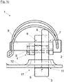
- Fig. 1c is a side view along in Fig. 1b shown line A - A and shows the type of locking in this embodiment.
- the pivoting parts 2, 3 are in the second pivoting position.
- a locking means 9 is formed here as a bolt with a securing bracket serving.
- the locking means 9 may be formed, for example, as a spring-loaded pressure piece.
- the blocking means 9 has been introduced by an operator in the second pivoting position of the pivoting parts 2, 3 into an opening 7 of the second pivoting part 3 and protrudes into the opening 6 arranged on the first pivoting part 2.
- Zurranker 1 In the case of a tensile load acting on Zurrantsch 8 Zurranker 1 can be prevented by the introduced into the openings 6, 7 blocking means 9, a pivoting of the pivot parts 2.3 to each other and so the Zurranker 1 are securely anchored in the anchoring opening 17.
- Fig. 2 shows a further embodiment of the Zurrankers 1, wherein in contrast to the in Fig. 1 embodiment shown, the openings 6, 7th are formed as passage openings in the material of the pivoting parts 2, 3 and in which additionally stops 13, 14 are arranged on the first pivot part 2.
- the Fig. 2a to 2e show a sequence of using the Zurrankers for anchoring a cargo, not shown, to a commercial vehicle, also not shown.
- the pivoting parts 2, 3 in the second pivot position In the Fig. 2d and 2e are the pivoting parts 2, 3 in the second pivot position.
- Fig. 2a 1 shows a pranger 1 which is arranged above a perforated plate 12 which is shown in the region of a selected anchoring opening 17.
- Fig. 2b The stops 13, 14 allow a supporting of the first pivoting part 2 at an upper side of a border of the anchoring opening 17. Because the first pivoting part 2 and thus the dresser 1 at are supported by the border, initially protrude only the extensions 5 of the pivoting parts 2, 3 in the anchoring opening 17 (see. Fig. 2b and 2c ). This prevents falling through of the dresser 1 through the perforated plate 12.
- By further lowering the Zurrankers 1 relative to the perforated plate 12 is a pivoting of the first pivot part 2 relative to the perforated plate 12 and the second pivot part 3.
- Fig. 2d shows the situation after the pivoting parts 2, 3 have been pivoted into the second pivoting position.
- the stops 13, 14 of the first pivoting part 2 are based on the border of the anchoring opening 17 from (due to the location of the in the Fig. 2d selected cutting plane of the perforated plate 12 is the Installation of the pivoting part 2 at the border of the opening of this figure is not apparent, but is for example in Fig. 4d clearly).
- the openings 6, 7 are aligned. In this way, a locking of the pivoting parts 2, 3 relative to each other with respect to a pivoting about the pivot axis S by inserting a locking means 9 (not shown, but see Fig. 2e ) take place in the aligned openings 6, 7.
- Fig. 2e shows the Zurranker 1 in the locked state.
- a hook 16 is inserted, with a lashing strap 18 is connected.
- the openings 6, 7 serve in this embodiment as Zurrantsch eighth
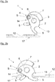
- Fig. 3 shows a further embodiment of the Zurrankers 1, in which as well as in Fig. 2 the openings 6, 7 are formed as passage openings in the material of the pivoting parts 2, 3 and in which also stops 13, 14 are arranged on the first pivot part 2.
- Fig. 2 have the first and the second pivot part 2, 3, a link 19, 20 and the openings 6, 6 ', 7, 7' are formed in the respective scenes 19, 20, wherein in or on the link 19, 20, a blocking means.
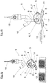
- the Fig. 4a to 4f show a sequence of using the Zurrankers for anchoring a cargo, not shown, to a commercial vehicle, also not shown.
- the Fig. 4g and 4h show rear views of the Fig. 4b or 4e.
- Fig. 4a shows a Zurranker 1 with two pivoted about the pivot axis S in the first pivot position swivel parts 2, 3.
- a closed with a bolt bracket (shackles) forms the Zurrantsch 8 and the locking means 9 from.
- a lashing strap 18 is struck with a hook 16 on the bump stop 8.
- the lashing strap 18 can strike directly on the ratchet 8.
- a captive lashing device can be provided.
- the Zurranker 1 is in Fig. 4a held by its own weight in the first pivot position, since the locking means 9 is located in the release opening 15 of the first pivot member 2 and is urged by the corresponding orientation of the release hole 15 and by the influence of gravity in this.
- the second pivot member 3 has been pivoted (raised) by the entry of the locking means in the release opening 15 of the first pivot member 2 and the limiter 1 thus has been brought into the first pivot position (see also Fig. 4g ).
- the Fig. 4b to 4f show a sequence of anchoring of the anchor 1 in an anchoring opening 17 in a perforated plate 12th
- Fig. 4b In this case, a retainer 1 arranged above a perforated plate 12 shown in the region of a selected anchoring opening 17 is shown.
- Fig. 4g shows a rear view of the Fig. 4b
- Fig. 4c the container 1 has been partially inserted into the anchoring opening 17.
- the release opening 15 of the restraint come to rest at a suspension on Zurrantsch 8 so that the extension 5 of the first pivoting part 2 protrudes when lowering the Zurrankers 1 as the first in the anchoring opening 17, thereby introducing the Zurrankers 1 can be facilitated.
- a further lowering the Zurrankers 1 can this as in Fig. 4d shown with the stop 13 come to rest on a border of the anchoring opening 17 to plant.
- the stops 13, 14 generally allow a supporting of the first pivoting part 2 at an upper side of a border of the anchoring opening 17, whereby a falling through of the dresser 1 through the perforated plate 12 can be prevented.
- a pivoting of the first pivot part 2 relative to the perforated plate 12 and the second pivot part 3 is carried out.
- the second pivot part 3 pivots relative to the perforated plate 12 and the first pivot part 2, so that the extensions 5 engage behind the border of the anchoring opening 17.
- the locking means 9 has been moved in the release opening 15, whereby the Zurranker 1 could be pivoted in the direction of its first pivot position. Upon further pivoting of the pivoting parts 2, 3 to each other, the locking means 9 escape from the release opening 15 of the first pivot member 2 and in the aligned in the first pivot position openings 6, 7 and 6 ', 7' are introduced.
- Fig. 4e shows the situation after further pivoting of the pivoting parts 2, 3 in the second pivot position, wherein the locking means 9 are inserted into the aligned in this first pivotal position openings 6, 7.
- the stops 13, 14 of the first pivoting part 2 are supported on the edge of the anchoring opening 17.
Abstract
Zurranker (1) mit: - einem Zurranschlag (8), - einem ersten plattenförmigen Schwenkteil (2), - einem zweiten plattenförmigen Schwenkteil (3), - einem Gelenk (4), welches die Schwenkteile (2, 3) relativ zueinander schwenkbar verbindet, wobei die Schwenkteile (2, 3) - sich quer zu einer durch das Gelenk (4) gehenden Schwenkachse (S) erstrecken, - in Richtung der Schwenkachse (S) nebeneinander angeordnet sind, - jeweils wenigstens einen Fortsatz (5) aufweisen, - zwischen einer ersten und einer zweiten Schwenkstellung um die Schwenkachse (S) zueinander verschwenkbar sind, wobei die auf unterschiedlichen Schwenkteilen (2, 3) angeordneten Fortsätze (5) in der ersten Schwenkstellung einen ersten Abstand aufweisen und in der zweiten Schwenkstellung einen zweiten, größeren Abstand aufweisen und - jeweils wenigstens eine Öffnung (6, 6', 7, 7') aufweisen, wobei die an oder in unterschiedlichen Schwenkteilen (2, 3) angeordneten Öffnungen (6, 6', 7, 7') in der zweiten Schwenkstellung der Schwenkteile (2, 3) fluchten, sodass die Schwenkteile (2, 3) in der zweiten Schwenkstellung durch Einführen eines Sperrmittels (9) in die fluchtenden Öffnungen (6, 6', 7, 7') in Bezug auf ein Verschwenken der Schwenkteile (2, 3) zueinander um die Schwenkachse (S) sperrbar sind.Zuranker (1) with: - a hunchback (8), a first plate-shaped pivoting part (2), a second plate-shaped pivoting part (3), - a hinge (4) which connects the pivoting parts (2, 3) pivotally relative to each other, the pivoting parts (2, 3) extending transversely to a pivot axis (S) passing through the hinge (4), - Are arranged side by side in the direction of the pivot axis (S), each have at least one extension (5), - Between a first and a second pivot position about the pivot axis (S) are mutually pivotable, wherein the on different pivot parts (2, 3) arranged extensions (5) in the first pivot position have a first distance and in the second pivot position, a second, larger Distance and have in each case at least one opening (6, 6 ', 7, 7'), the openings (6, 6 ', 7, 7') arranged on or in different pivoting parts (2, 3) being in the second pivoting position of the pivoting parts ( 2, 3) are aligned, so that the pivoting parts (2, 3) in the second pivoting position by inserting a locking means (9) in the aligned openings (6, 6 ', 7, 7') with respect to a pivoting of the pivoting parts (2, 3) to each other about the pivot axis (S) can be blocked.
Description
Die Erfindung betrifft einen Zurranker mit den Merkmalen des Oberbegriffs des Anspruchs 1 und eine Verwendung eines solchen Zurrankers.The invention relates to a Zurranker with the features of the preamble of
Ein gattungsgemäßer Zurranker geht aus der
Aufgabe der Erfindung ist die Bereitstellung eines einfacheren, universeller einsetzbaren Zurrankers, der sich insbesondere zum Verzurren von Ladegut auf einem Nutzfahrzeug eignet.The object of the invention is to provide a simpler, universally applicable Zurrankers, which is particularly suitable for lashing cargo on a commercial vehicle.
Diese Aufgabe wird durch einen Zurranker mit den Merkmalen des Anspruchs 1 und die Verwendung eines solchen Zurrankers zum Verzurren von Ladegut auf einem Nutzfahrzeug gelöst. Vorteilhafte Ausführungsformen der Erfindung sind in den abhängigen Ansprüchen definiert.This object is achieved by a Zurranker with the features of
Ein solcher Zurranker kann klein gebaut werden, weist nur wenige Teile auf und kann an einer einzigen Verankerungsöffnung verankert werden. Da sich die Schwenkteile quer zu einer durch das Gelenk gehenden Schwenkachse erstrecken, können sie in der zweiten Schwenkstellung (Sperrstellung der Schwenkteile bzw. Zurrstellung des Zurrankers) eine die Verankerungsöffnung bildende Umrandung hintergreifen. Weil die Schwenkteile in Richtung der Schwenkachse nebeneinander angeordnet sind, jeweils wenigstens eine Öffnung aufweisen und die an oder in unterschiedlichen Schwenkteilen angeordneten Öffnungen in der zweiten Schwenkstellung fluchten, ist auf einfache Weise in der zweiten Schwenkstellung ein Sperren der Schwenkteile in Bezug auf ein Verschwenken der Schwenkteile zueinander um die Schwenkachse durch Einführen eines Sperrmittels in die fluchtenden Öffnungen möglich. In einer Minimalvariante kommt die Erfindung also mit nur drei Teilen aus (erstes Schwenkteil, zweites Schwenkteil, Gelenk). In dieser Variante können die fluchtenden Öffnungen als Zurranschlag dienen.Such a container can be made small, has only a few parts and can be anchored to a single anchoring opening. Since the pivoting parts extend transversely to a pivot axis passing through the joint, in the second pivoting position (blocking position of the pivoting parts or lashing position of the locking device) they can engage behind an edge forming the anchoring opening. Because the pivot parts are arranged side by side in the direction of the pivot axis, each having at least one opening and the openings arranged in or on different pivoting parts in the second pivot position is easily in the second pivot position, a locking of the pivot parts with respect to a pivoting of the pivot parts to each other about the pivot axis by inserting a locking means in the aligned openings possible. In a minimal variant, the invention thus comes with only three parts (first pivot part, second pivot part, joint). In this variant, the aligned openings can serve as Zurranschlag.
Als Zurranschlag kann ein für eine Zugbelastung geeigneter Anschlagpunkt verstanden werden. Unter einer plattenförmigen Ausbildung der Schwenkteile kann eine im Wesentlichen ebene und im Vergleich zur Quer- bzw. Längserstreckung mit geringer Tiefenerstreckung (Materialstärke) erfolgende Ausbildung verstanden werden. Als eine Verankerungsöffnung kann dabei beispielsweise ein Durchgangsloch, insbesondere ein Langloch, in einer Platte, beispielsweise einem Lochblech, verstanden werden. Ebenso ist eine Verankerungsöffnung in Form einer T-Nut denkbar.When Zurranschlag can be understood as suitable for a tensile load attachment point. Under a plate-shaped design of the pivoting parts can be understood a substantially flat and compared to the transverse or longitudinal extent with a small depth extension (material thickness) training education. As an anchoring opening can be understood, for example, a through hole, in particular a slot in a plate, such as a perforated plate. Likewise, an anchoring opening in the form of a T-groove is conceivable.
Wenn zumindest das erste Schwenkteil wenigstens einen Anschlag aufweist, kann sich zumindest das erste Schwenkteil an einem Rand einer Verankerungsöffnung abstützen. Dadurch kann ein Hineinfallen des Zurrankers in die Verankerungsöffnung vermieden werden. Auch kann ein Überführen des Zurrankers aus der ersten Schwenkstellung in die zweite Schwenkstellung erleichtert werden, da sich das erste Schwenkteil durch die Abstützung relativ zu der Verankerungsöffnung verschwenken lassen kann.If at least the first pivoting part has at least one stop, at least the first pivoting part can be supported on an edge of an anchoring opening. As a result, a dropping in of the Zurrankers can be avoided in the anchoring opening. Also, a transfer of the limiter from the first pivot position into the second pivot position can be facilitated because the first pivot part can be pivoted by the support relative to the anchoring opening.
Es kann vorteilhaft sein, wenn die Fortsätze an unterschiedlichen Schwenkteilen in unterschiedliche Richtungen verlaufen. Dadurch kann ein Verspreizen des Zurrankers in einer Verankerungsöffnung erleichtert werden. Durch einen solchen Verlauf kann auch ein Hintergreifen einer Verankerungsöffnung erleichtert werden.It may be advantageous if the projections extend at different pivoting parts in different directions. This can be a spreading of the Zurrankers be facilitated in an anchoring opening. By such a course, a gripping behind an anchoring opening can be facilitated.
Es kann vorteilhaft sein, dass die Fortsätze quer zur Schwenkachse verlaufen. Dadurch kann einfach erreicht werden, dass die Fortsätze in den Schwenkstellung des Zurrankers unterschiedliche Abstände aufweisen. Auch kann dadurch ein Hintergreifen einer Verankerungsöffnung durch die Fortsätze bei einem Verschwenken der Schwenkteile zueinander besonders einfach erreicht werden.It may be advantageous for the extensions to run transversely to the pivot axis. As a result, it can be easily achieved that the extensions have different distances in the pivoting position of the locking device. Also, this can reach behind an anchoring opening by the extensions be achieved particularly easily when pivoting the pivot parts to each other.
Es kann weiter von Vorteil sein, wenn der Zurranker ein Sperrmittel aufweist. Dadurch kann sich ein Sperren der Schwenkteile in Bezug auf ein Verschwenken der Schwenkteile zueinander ermöglichen lassen.It may also be advantageous for the passenger to have a blocking means. As a result, a locking of the pivoting parts in relation to a pivoting of the pivoting parts relative to one another can be made possible.
Dabei kann vorteilhaft sein, wenn das Sperrmittel den Zurranschlag aufweist und vorzugsweise ringförmig ausgebildet ist. Das Sperrmittel kann dadurch die Doppelfunktion des Sperrens der Schwenkteile in Bezug auf ein Verschwenken der Schwenkteile zueinander und der Bereitstellung eines Zurranschlags, also eines Anschlagpunkts für beispielsweise einen Zurrgurt, übernehmen. Dadurch kann sich die Anzahl der benötigten Teile, sowie die zur Herstellung nötigen Arbeitsschritte, verringern lassen. Durch eine im Wesentlichen ringförmige Ausbildung des Sperrmittels kann es zu einer vorteilhaften Ausbildung des Sperrmittels und des durch dieses ausgebildeten Zurranschlags kommen.It may be advantageous if the locking means has the Zurranschlag and is preferably annular. The blocking means can thereby assume the double function of blocking the pivoting parts with respect to pivoting of the pivoting parts relative to one another and providing a ratcheting impact, that is to say an attachment point for, for example, a lashing strap. As a result, the number of parts required, as well as the necessary steps for the production, can be reduced. By a substantially annular design of the locking means, it can lead to an advantageous embodiment of the locking means and the trained by this Zurranschlags.
Auch kann vorteilhaft sein, dass der Zurranker ein Sperrmittel aufweist, welches in der zweiten Schwenkstellung der Schwenkteile in die fluchtenden Öffnungen zum Sperren der Schwenkteile in Bezug auf ein Verschwenken der Schwenkteile zueinander um die Schwenkachse einführbar ist. Durch ein solches Sperren oder Fixieren der Schwenkteile zueinander kann der Zurranker dauerhaft in der zweiten Schwenkstellung gehalten werden. Der Zurranker kann dadurch in der Verankerungsöffnung, insbesondere gegen Zugbelastungen, verankert werden. Wenn das erste Schwenkteil zusätzlich zumindest einen Anschlag zur Abstützung an einem Rand einer Verankerungsöffnung aufweist, kann der Zurranker in der Verankerungsöffnung gegen Schub- und Zugbelastungen verankert werden. Das Sperrmittel kann dabei lösbar ausgebildet sein.It can also be advantageous for the operator to have a blocking means which can be inserted in the second pivoting position of the pivoting parts into the aligned openings for locking the pivoting parts relative to pivoting of the pivoting parts relative to one another about the pivot axis. By such locking or fixing the pivot parts to each other, the retractor can be kept permanently in the second pivot position. The Zurranker can thereby be anchored in the anchoring opening, in particular against tensile loads. If the first pivoting part additionally has at least one stop for support on an edge of an anchoring opening, the retractor can be anchored in the anchoring opening against thrust and tensile loads. The blocking means can be designed to be detachable.
Es kann weiter von Vorteil sein, wenn das Gelenk exzentrisch an den Schwenkteilen angeordnet ist und die Öffnungen zentral an den Schwenkteilen angeordnet sind. Dadurch kann beispielweise erreicht werden, dass die die an oder in unterschiedlichen Schwenkteilen angeordneten Öffnungen in der zweiten Schwenkstellung fluchten und bei einem Verschwenken der Schwenkteile zueinander aus dieser zweiten Schwenkstellung heraus zueinander versetzt zu liegen kommen. Ist in der zweiten Schwenkstellung ein Sperrmittel in die Öffnungen eingeführt, so kann ein solches Verschwenken der Schwenkteile zueinander verhindert werden.It may also be advantageous if the joint is arranged eccentrically on the pivoting parts and the openings centrally on the pivoting parts are arranged. As a result, it can be achieved, for example, that the openings arranged on or in different pivoting parts are aligned in the second pivoting position and, when the pivoting parts are pivoted relative to one another, come out of this second pivoting position. If, in the second pivoting position, a blocking means is introduced into the openings, then such pivoting of the pivoting parts relative to one another can be prevented.
Es kann vorteilhaft sein, dass das erste und das zweite Schwenkteil eine Kulisse aufweisen und die Öffnungen in den jeweiligen Kulissen ausgebildet sind. Die Kulissen sowie die Öffnungen können als Durchgangsloch und/oder als Ausnehmungen in den Schwenkteilen ausgebildet sein.It may be advantageous that the first and the second pivot part have a backdrop and the openings are formed in the respective scenes. The scenes and the openings may be formed as a through hole and / or as recesses in the pivoting parts.
Dabei kann es vorteilhaft sein, wenn in oder an der Kulisse ein Sperrmittel verfahrbar ist und die im oder am ersten Schwenkteil angeordnete Kulisse eine mit der Öffnung verbundene Löseöffnung aufweist, wobei bei einem in der Löseöffnung angeordneten Sperrmittel das in der zweiten Schwenkstellung vorgesehene Sperren der Schwenkteile aufgehoben ist, und sich die Schwenkteile in der ersten Schwenkstellung befinden. Dabei kann ein Verfahren bzw. Bewegen des Sperrmittels aus der Öffnung in die Löseöffnung eine Sperre der relativen Verschwenkbarkeit der Schwenkteile zueinander aufgehoben werden. Auch kann durch ein solches Verfahren bzw. eine solche Bewegung der Zurranker von der zweiten Schwenkstellung in die erste Schwenkstellung überführt werden. Dadurch, dass die im oder am ersten Schwenkteil angeordnete Kulisse eine mit der Öffnung verbundene Löseöffnung aufweist kann bei entsprechender Ausformung der Öffnungen und der Kulissen bei einem Verfahren bzw. Bewegen eines Sperrmittels in die Löseöffnung ein Verschwenken der Schwenkteile zueinander bewirkt werden.It may be advantageous if in or on the backdrop, a blocking means is movable and arranged in or on the first pivot part gate has a release opening connected to the opening, wherein at a arranged in the release opening blocking means provided in the second pivot position locks the pivot parts is lifted, and the pivoting parts are in the first pivot position. In this case, a method or movement of the locking means from the opening into the release opening a blockage of the relative pivotability of the pivot parts to each other can be canceled. Also, by such a method or such a movement of the limiter can be transferred from the second pivot position to the first pivot position. Characterized in that the arranged in or on the first pivot part gate has a release opening connected to the opening can be effected with appropriate shaping of the openings and the scenes in a process or moving a locking means in the release opening a pivoting of the pivot parts to each other.
Dabei kann vorgesehen sein, dass bei einem Anheben des Zurrankers, wenn sich dieser in der zweiten Schwenkstellung der Schwenkteile befindet, durch das Eigengewicht des Zurrankers oder durch eine Kontaktierung zumindest eines der Fortsätze an einer Umrandung einer Verankerungsöffnung das Sperrmittel in die Löseöffnung gerät. So kann beispielsweise durch eine geeignete Positionierung des Sperrmittels innerhalb der Öffnungen und der Kulisse ein beabsichtigtes Überführen des Zurrankers aus der zweiten Schwenkstellung der Schwenkteile in die erste Schwenkstellung der Schwenkteile zueinander ermöglicht werden. Dies kann zum Beispiel ein beabsichtigtes Lösen eines in einer Verankerungsöffnung verankerten Zurrankers erlauben. Auch kann dadurch ein Zurranker durch sein Eigengewicht in der ersten Schwenkstellung gehalten werden.It can be provided that, when the driveline is raised when it is in the second swivel position of the swiveling parts, it is at least connected by the own weight of the dredger or by a contact one of the extensions on a border of an anchoring opening the blocking means in the release opening device. Thus, for example, by a suitable positioning of the blocking means within the openings and the backdrop, an intentional transfer of the limiter from the second pivoting position of the pivoting parts into the first pivoting position of the pivoting parts relative to one another is made possible. This may, for example, allow an intentional release of a anchor anchored in an anchoring opening. Also, this can be held by his own weight in the first pivot position a Zurranker.
Es kann weiter von Vorteil sein, wenn mit dem Zurranker ein Zurrgurt verbunden ist. Dadurch kann sich ein besonders leicht bedienbares Zurrzeug schaffen lassen. Dabei kann beispielsweise ein mit dem Zurrgurt verbundener Haken als Sperrmittel dienen. An Stelle eines Hakens kann auch ein mit einem Schraub- oder Steckbolzen verschließbarer Bügel (Schäkel) verwendet werden, wobei von diesem auch die Doppelfunktion des Sperrmittels und des Zurranschlags übernommen werden kann.It can also be advantageous if a lashing strap is connected to the trailer. This can create a particularly easy-to-use lashing. In this case, for example, a hook connected to the lashing strap can serve as a blocking means. Instead of a hook can also be used with a screw or locking pin closable bracket (shackle), which can also be assumed by this the double function of the locking means and the Zurranschlags.
Bei einer Verwendung eines wie zuvor beschriebenen Zurrankers kann dieser zum Verzurren von Ladegut, insbesondere Fahrzeugen, auf einem Nutzfahrzeug, insbesondere auf einem Fahrblech eines Fahrzeugtransporters zum Einsatz kommen. Dabei kann das Fahrblech als Lochblech ausgebildet sein und der Zurranker in Löchern des Lochblechs verankerbar sein.When using a drone as described above, it can be used for lashing loads, in particular vehicles, on a commercial vehicle, in particular on a lane of a vehicle transporter. In this case, the lane plate may be formed as a perforated plate and the Zurranker be anchored in holes of the perforated plate.
Verschiedene Ausführungsbeispiele der Erfindung werden anhand der Figuren diskutiert. Es zeigen:
- Fig. 1a - 1c
- ein erstes Ausführungsbeispiel eines erfindungsgemäßen Zurrankers,
- Fig. 2a - 2e
- ein zweites Ausführungsbeispiel eines erfindungsgemäßen Zurrankers,
- Fig. 3
- ein drittes Ausführungsbeispiel eines erfindungsgemäßen Zurrankers in einer Explosionsdarstellung und
- Fig. 4a - 4h
- weitere Ansichten zum Ausführungsbeispiel der
Fig. 3 .
- Fig. 1a - 1c
- A first embodiment of a drone according to the invention,
- Fig. 2a - 2e
- A second embodiment of a drone according to the invention,
- Fig. 3
- a third embodiment of a Zurrankers invention in an exploded view and
- Fig. 4a - 4h
- further views of the embodiment of
Fig. 3 ,
Bei allen Ausführungsbeispielen weist der Zurranker 1 ein erstes und ein zweites plattenförmiges Schwenkteil 2, 3 auf, die über ein Gelenk 4 miteinander verbunden sind und in Bezug auf eine durch das Gelenk 4 gehende Schwenkachse S relativ zueinander verschwenkbar sind.In all embodiments, the
Die Schwenkteile 2, 3 erstrecken sich quer zur Schwenkachse S. Jedes Schwenkteil 2, 3 weist einen (in den Figuren einzigen) Fortsatz 5 auf. Es können pro Schwenkteil 2, 3 mehrere, vorzugsweise parallel zueinander verlaufende Fortsätze 5 vorgesehen sein. Die an unterschiedlichen Schwenkteilen 2, 3 angeordneten Fortsätze 5 verlaufen in unterschiedlichen Richtungen. In der zweiten Schwenkstellung der Schwenkteile 2, 3 verlaufen die Fortsätze 5 in wenigstens annähernd entgegengesetzte Richtungen.The pivoting
Die Schwenkteile 2, 3 weisen jeweils wenigstens eine Öffnung 6, 6', 7, 7' auf. Öffnungen 6, 6', 7, 7' die an oder in unterschiedlichen Schwenkteilen 2, 3 angeordnet sind, fluchten in der zweiten Schwenkstellung, sodass die Schwenkteile 2, 3 in der zweiten Schwenkstellung durch Einführen eines Sperrmittels 9 in die fluchtenden Öffnungen 6, 7 bzw. ggf. 6', 7' in Bezug auf ein Verschwenken der Schwenkteile 2, 3 zueinander um die Schwenkachse S sperrbar sind. Das Sperrmittel 9 kann Teil des Zurrankers 1 sein, dies ist aber nicht unbedingt erforderlich.The pivoting
Zu den Figuren im Einzelnen:
-
Fig. 1a, 1b ,1c zeigen ein erstes Ausführungsbeispiel der Erfindung. In denFig. 1a und 1b verläuft die Schwenkachse S rechtwinklig zur Blattebene.
-
Fig. 1a, 1b .1c show a first embodiment of the invention. In theFig. 1a and 1b the pivot axis S runs at right angles to the page plane.
In
In
Bei diesem Ausführungsbeispiel ist die Öffnung 6 als Ausnehmung am ersten Schwenkteil 2 ausgebildet. Der Zurranschlag 8 ist in Form einer am ersten Schwenkteil 2 angeordneten Öse ausgebildet.In this embodiment, the
Die
Die
Der Zurranker 1 ist in
Die
In
Bein einem weiteren Absenken des Zurrankers 1 kann dieser wie in
Bei einer wie in
- 11
- Zurrankerlashing strap buckles
- 22
- erstes Schwenkteilfirst pivoting part
- 33
- zweites Schwenkteilsecond pivot part
- 44
- Gelenkjoint
- 55
- Fortsatzextension
- 6, 6'6, 6 '
- Öffnung im ersten SchwenkteilOpening in the first pivoting part
- 7, 7'7, 7 '
- Öffnung im zweiten SchwenkteilOpening in the second pivot part
- 88th
- ZurranschlagZurranschlag
- 99
- Sperrmittelblocking means
- 1010
- Positionposition
- 1111
- Positionposition
- 1212
- Lochblechperforated sheet
- 1313
- Anschlag an SchwenkteilStop at swivel part
- 1414
- Anschlag an SchwenkteilStop at swivel part
- 1515
- Löseöffnungrelease opening
- 1616
- Hakenhook
- 1717
- Verankerungsöffnunganchoring opening
- 1818
- Zurrgurtlashing
- 1919
- Kulissescenery
- 2020
- Kulissescenery
- SS
- Schwenkachseswivel axis
Claims (13)
dadurch gekennzeichnet, dass die Schwenkteile (2, 3)
characterized in that the pivoting parts (2, 3)
Applications Claiming Priority (1)
| Application Number | Priority Date | Filing Date | Title |
|---|---|---|---|
| AT504532016 | 2016-05-17 |
Publications (2)
| Publication Number | Publication Date |
|---|---|
| EP3246202A1 true EP3246202A1 (en) | 2017-11-22 |
| EP3246202B1 EP3246202B1 (en) | 2020-09-09 |
Family
ID=58709360
Family Applications (1)
| Application Number | Title | Priority Date | Filing Date |
|---|---|---|---|
| EP17171044.5A Active EP3246202B1 (en) | 2016-05-17 | 2017-05-15 | Lashing anchor |
Country Status (1)
| Country | Link |
|---|---|
| EP (1) | EP3246202B1 (en) |
Citations (6)
| Publication number | Priority date | Publication date | Assignee | Title |
|---|---|---|---|---|
| DE2945550A1 (en) * | 1978-11-20 | 1980-05-29 | William L Mccullough | LOAD CARRIER |
| US20070207003A1 (en) * | 2006-03-01 | 2007-09-06 | Warren Roh | Cargo restraint anchor device for pick-up trucks |
| US20080304930A1 (en) | 2007-06-08 | 2008-12-11 | Holland Company | Wheel restraint assembly and method |
| US20100143064A1 (en) * | 2008-03-11 | 2010-06-10 | Gomez David L | Adjustable tie-down apparatus for pickup trucks |
| DE202010008543U1 (en) * | 2010-09-15 | 2010-11-25 | MÜNZ-Fahrzeugbau GmbH & Co. KG | Lashing eye assembly for a vehicle with a cargo floor |
| WO2011143042A1 (en) * | 2010-05-10 | 2011-11-17 | Maaj Research And Development, Inc. | Portable and removable anchor for truck bed slots |
-
2017
- 2017-05-15 EP EP17171044.5A patent/EP3246202B1/en active Active
Patent Citations (6)
| Publication number | Priority date | Publication date | Assignee | Title |
|---|---|---|---|---|
| DE2945550A1 (en) * | 1978-11-20 | 1980-05-29 | William L Mccullough | LOAD CARRIER |
| US20070207003A1 (en) * | 2006-03-01 | 2007-09-06 | Warren Roh | Cargo restraint anchor device for pick-up trucks |
| US20080304930A1 (en) | 2007-06-08 | 2008-12-11 | Holland Company | Wheel restraint assembly and method |
| US20100143064A1 (en) * | 2008-03-11 | 2010-06-10 | Gomez David L | Adjustable tie-down apparatus for pickup trucks |
| WO2011143042A1 (en) * | 2010-05-10 | 2011-11-17 | Maaj Research And Development, Inc. | Portable and removable anchor for truck bed slots |
| DE202010008543U1 (en) * | 2010-09-15 | 2010-11-25 | MÜNZ-Fahrzeugbau GmbH & Co. KG | Lashing eye assembly for a vehicle with a cargo floor |
Also Published As
| Publication number | Publication date |
|---|---|
| EP3246202B1 (en) | 2020-09-09 |
Similar Documents
| Publication | Publication Date | Title |
|---|---|---|
| DE3830493C2 (en) | Belt force limiting device | |
| DE4325662A1 (en) | Device for height adjustment of a seat belt fitting | |
| DE202018106361U1 (en) | Fitting for load securing | |
| DE102016205836A1 (en) | Hook for moving formwork elements | |
| EP3246202A1 (en) | Lashing anchor | |
| DE10120538A1 (en) | Holding lock for attaching a child car seat to an anchor | |
| EP2805083B1 (en) | Cable end connection and cable socket for a cable end connection | |
| DE10106920A1 (en) | Securing device for loads on vehicle seats comprises luggage strap with belt tongue locking into lock of seat belt system and with socket to receive locking part at other end of strap | |
| EP3033961B1 (en) | Belt buckle assembly | |
| AT504478B1 (en) | Hold-down device for coupling of drawing vehicle, has fastening bolt arranged for fixation into aperture at coupling position and formed opposite to aperture, which is designed in bent-form | |
| DE102006021887B4 (en) | Locking device for a vehicle seat | |
| DE19605824C1 (en) | Head connection for pipe with radially extending head-plate | |
| DE102012111642A1 (en) | Commercial vehicle structure for commercial vehicles, particularly semi-trailer or semi-trailer bottom plate, has sliding plane which is movable for closing and realizing load opening in closed position and in open position | |
| DE60027948T2 (en) | Device for securing loads | |
| AT523664B1 (en) | transport hook | |
| AT15807U1 (en) | Use of a anchor for anchoring a lashing device | |
| EP3463239B1 (en) | Mobility aid | |
| EP0212322A2 (en) | Removable trailer coupling | |
| DE102006005387A1 (en) | Vehicle roof-drop testing device, has assembly platform, which has several fastening parts for detachable connection at automotive welding and assembly lines of motor vehicle | |
| DE102015109172B4 (en) | Commercial vehicle body with a tarpaulin, commercial vehicle with such a commercial vehicle body and method for producing a commercial vehicle body | |
| EP3742021B1 (en) | Shortening clutch for tensioning a lashing chain | |
| EP3594431B1 (en) | Holding system for transporting finished concrete products | |
| EP3929033B1 (en) | Charge protection network and emergency release device for same | |
| EP3763238B1 (en) | Belt lock, belt lock system and aircraft safety belt | |
| DE102017117986B4 (en) | Transport device for securing goods to be transported on vehicles |
Legal Events
| Date | Code | Title | Description |
|---|---|---|---|
| PUAI | Public reference made under article 153(3) epc to a published international application that has entered the european phase |
Free format text: ORIGINAL CODE: 0009012 |
|
| STAA | Information on the status of an ep patent application or granted ep patent |
Free format text: STATUS: THE APPLICATION HAS BEEN PUBLISHED |
|
| AK | Designated contracting states |
Kind code of ref document: A1 Designated state(s): AL AT BE BG CH CY CZ DE DK EE ES FI FR GB GR HR HU IE IS IT LI LT LU LV MC MK MT NL NO PL PT RO RS SE SI SK SM TR |
|
| AX | Request for extension of the european patent |
Extension state: BA ME |
|
| STAA | Information on the status of an ep patent application or granted ep patent |
Free format text: STATUS: REQUEST FOR EXAMINATION WAS MADE |
|
| 17P | Request for examination filed |
Effective date: 20180518 |
|
| RBV | Designated contracting states (corrected) |
Designated state(s): AL AT BE BG CH CY CZ DE DK EE ES FI FR GB GR HR HU IE IS IT LI LT LU LV MC MK MT NL NO PL PT RO RS SE SI SK SM TR |
|
| GRAP | Despatch of communication of intention to grant a patent |
Free format text: ORIGINAL CODE: EPIDOSNIGR1 |
|
| STAA | Information on the status of an ep patent application or granted ep patent |
Free format text: STATUS: GRANT OF PATENT IS INTENDED |
|
| RIC1 | Information provided on ipc code assigned before grant |
Ipc: B60P 3/077 20060101AFI20191129BHEP Ipc: B60P 3/079 20060101ALI20191129BHEP Ipc: B60P 7/08 20060101ALI20191129BHEP |
|
| INTG | Intention to grant announced |
Effective date: 20191220 |
|
| GRAS | Grant fee paid |
Free format text: ORIGINAL CODE: EPIDOSNIGR3 |
|
| GRAA | (expected) grant |
Free format text: ORIGINAL CODE: 0009210 |
|
| STAA | Information on the status of an ep patent application or granted ep patent |
Free format text: STATUS: THE PATENT HAS BEEN GRANTED |
|
| AK | Designated contracting states |
Kind code of ref document: B1 Designated state(s): AL AT BE BG CH CY CZ DE DK EE ES FI FR GB GR HR HU IE IS IT LI LT LU LV MC MK MT NL NO PL PT RO RS SE SI SK SM TR |
|
| REG | Reference to a national code |
Ref country code: GB Ref legal event code: FG4D Free format text: NOT ENGLISH |
|
| REG | Reference to a national code |
Ref country code: AT Ref legal event code: REF Ref document number: 1311189 Country of ref document: AT Kind code of ref document: T Effective date: 20200915 Ref country code: CH Ref legal event code: EP |
|
| REG | Reference to a national code |
Ref country code: IE Ref legal event code: FG4D Free format text: LANGUAGE OF EP DOCUMENT: GERMAN |
|
| REG | Reference to a national code |
Ref country code: DE Ref legal event code: R096 Ref document number: 502017007117 Country of ref document: DE |
|
| REG | Reference to a national code |
Ref country code: LT Ref legal event code: MG4D |
|
| PG25 | Lapsed in a contracting state [announced via postgrant information from national office to epo] |
Ref country code: LT Free format text: LAPSE BECAUSE OF FAILURE TO SUBMIT A TRANSLATION OF THE DESCRIPTION OR TO PAY THE FEE WITHIN THE PRESCRIBED TIME-LIMIT Effective date: 20200909 Ref country code: SE Free format text: LAPSE BECAUSE OF FAILURE TO SUBMIT A TRANSLATION OF THE DESCRIPTION OR TO PAY THE FEE WITHIN THE PRESCRIBED TIME-LIMIT Effective date: 20200909 Ref country code: BG Free format text: LAPSE BECAUSE OF FAILURE TO SUBMIT A TRANSLATION OF THE DESCRIPTION OR TO PAY THE FEE WITHIN THE PRESCRIBED TIME-LIMIT Effective date: 20201209 Ref country code: GR Free format text: LAPSE BECAUSE OF FAILURE TO SUBMIT A TRANSLATION OF THE DESCRIPTION OR TO PAY THE FEE WITHIN THE PRESCRIBED TIME-LIMIT Effective date: 20201210 Ref country code: FI Free format text: LAPSE BECAUSE OF FAILURE TO SUBMIT A TRANSLATION OF THE DESCRIPTION OR TO PAY THE FEE WITHIN THE PRESCRIBED TIME-LIMIT Effective date: 20200909 Ref country code: NO Free format text: LAPSE BECAUSE OF FAILURE TO SUBMIT A TRANSLATION OF THE DESCRIPTION OR TO PAY THE FEE WITHIN THE PRESCRIBED TIME-LIMIT Effective date: 20201209 Ref country code: HR Free format text: LAPSE BECAUSE OF FAILURE TO SUBMIT A TRANSLATION OF THE DESCRIPTION OR TO PAY THE FEE WITHIN THE PRESCRIBED TIME-LIMIT Effective date: 20200909 |
|
| PG25 | Lapsed in a contracting state [announced via postgrant information from national office to epo] |
Ref country code: PL Free format text: LAPSE BECAUSE OF FAILURE TO SUBMIT A TRANSLATION OF THE DESCRIPTION OR TO PAY THE FEE WITHIN THE PRESCRIBED TIME-LIMIT Effective date: 20200909 Ref country code: RS Free format text: LAPSE BECAUSE OF FAILURE TO SUBMIT A TRANSLATION OF THE DESCRIPTION OR TO PAY THE FEE WITHIN THE PRESCRIBED TIME-LIMIT Effective date: 20200909 Ref country code: LV Free format text: LAPSE BECAUSE OF FAILURE TO SUBMIT A TRANSLATION OF THE DESCRIPTION OR TO PAY THE FEE WITHIN THE PRESCRIBED TIME-LIMIT Effective date: 20200909 |
|
| PG25 | Lapsed in a contracting state [announced via postgrant information from national office to epo] |
Ref country code: EE Free format text: LAPSE BECAUSE OF FAILURE TO SUBMIT A TRANSLATION OF THE DESCRIPTION OR TO PAY THE FEE WITHIN THE PRESCRIBED TIME-LIMIT Effective date: 20200909 Ref country code: SM Free format text: LAPSE BECAUSE OF FAILURE TO SUBMIT A TRANSLATION OF THE DESCRIPTION OR TO PAY THE FEE WITHIN THE PRESCRIBED TIME-LIMIT Effective date: 20200909 Ref country code: RO Free format text: LAPSE BECAUSE OF FAILURE TO SUBMIT A TRANSLATION OF THE DESCRIPTION OR TO PAY THE FEE WITHIN THE PRESCRIBED TIME-LIMIT Effective date: 20200909 Ref country code: PT Free format text: LAPSE BECAUSE OF FAILURE TO SUBMIT A TRANSLATION OF THE DESCRIPTION OR TO PAY THE FEE WITHIN THE PRESCRIBED TIME-LIMIT Effective date: 20210111 Ref country code: CZ Free format text: LAPSE BECAUSE OF FAILURE TO SUBMIT A TRANSLATION OF THE DESCRIPTION OR TO PAY THE FEE WITHIN THE PRESCRIBED TIME-LIMIT Effective date: 20200909 |
|
| PG25 | Lapsed in a contracting state [announced via postgrant information from national office to epo] |
Ref country code: AL Free format text: LAPSE BECAUSE OF FAILURE TO SUBMIT A TRANSLATION OF THE DESCRIPTION OR TO PAY THE FEE WITHIN THE PRESCRIBED TIME-LIMIT Effective date: 20200909 Ref country code: ES Free format text: LAPSE BECAUSE OF FAILURE TO SUBMIT A TRANSLATION OF THE DESCRIPTION OR TO PAY THE FEE WITHIN THE PRESCRIBED TIME-LIMIT Effective date: 20200909 Ref country code: IS Free format text: LAPSE BECAUSE OF FAILURE TO SUBMIT A TRANSLATION OF THE DESCRIPTION OR TO PAY THE FEE WITHIN THE PRESCRIBED TIME-LIMIT Effective date: 20210109 |
|
| REG | Reference to a national code |
Ref country code: DE Ref legal event code: R097 Ref document number: 502017007117 Country of ref document: DE |
|
| PG25 | Lapsed in a contracting state [announced via postgrant information from national office to epo] |
Ref country code: SK Free format text: LAPSE BECAUSE OF FAILURE TO SUBMIT A TRANSLATION OF THE DESCRIPTION OR TO PAY THE FEE WITHIN THE PRESCRIBED TIME-LIMIT Effective date: 20200909 |
|
| PLBE | No opposition filed within time limit |
Free format text: ORIGINAL CODE: 0009261 |
|
| STAA | Information on the status of an ep patent application or granted ep patent |
Free format text: STATUS: NO OPPOSITION FILED WITHIN TIME LIMIT |
|
| 26N | No opposition filed |
Effective date: 20210610 |
|
| PG25 | Lapsed in a contracting state [announced via postgrant information from national office to epo] |
Ref country code: DK Free format text: LAPSE BECAUSE OF FAILURE TO SUBMIT A TRANSLATION OF THE DESCRIPTION OR TO PAY THE FEE WITHIN THE PRESCRIBED TIME-LIMIT Effective date: 20200909 Ref country code: SI Free format text: LAPSE BECAUSE OF FAILURE TO SUBMIT A TRANSLATION OF THE DESCRIPTION OR TO PAY THE FEE WITHIN THE PRESCRIBED TIME-LIMIT Effective date: 20200909 |
|
| REG | Reference to a national code |
Ref country code: NL Ref legal event code: FP |
|
| REG | Reference to a national code |
Ref country code: CH Ref legal event code: PL |
|
| GBPC | Gb: european patent ceased through non-payment of renewal fee |
Effective date: 20210515 |
|
| PG25 | Lapsed in a contracting state [announced via postgrant information from national office to epo] |
Ref country code: CH Free format text: LAPSE BECAUSE OF NON-PAYMENT OF DUE FEES Effective date: 20210531 Ref country code: LI Free format text: LAPSE BECAUSE OF NON-PAYMENT OF DUE FEES Effective date: 20210531 Ref country code: LU Free format text: LAPSE BECAUSE OF NON-PAYMENT OF DUE FEES Effective date: 20210515 Ref country code: MC Free format text: LAPSE BECAUSE OF FAILURE TO SUBMIT A TRANSLATION OF THE DESCRIPTION OR TO PAY THE FEE WITHIN THE PRESCRIBED TIME-LIMIT Effective date: 20200909 |
|
| REG | Reference to a national code |
Ref country code: BE Ref legal event code: MM Effective date: 20210531 |
|
| PG25 | Lapsed in a contracting state [announced via postgrant information from national office to epo] |
Ref country code: IE Free format text: LAPSE BECAUSE OF NON-PAYMENT OF DUE FEES Effective date: 20210515 Ref country code: GB Free format text: LAPSE BECAUSE OF NON-PAYMENT OF DUE FEES Effective date: 20210515 |
|
| PG25 | Lapsed in a contracting state [announced via postgrant information from national office to epo] |
Ref country code: BE Free format text: LAPSE BECAUSE OF NON-PAYMENT OF DUE FEES Effective date: 20210531 |
|
| PG25 | Lapsed in a contracting state [announced via postgrant information from national office to epo] |
Ref country code: HU Free format text: LAPSE BECAUSE OF FAILURE TO SUBMIT A TRANSLATION OF THE DESCRIPTION OR TO PAY THE FEE WITHIN THE PRESCRIBED TIME-LIMIT; INVALID AB INITIO Effective date: 20170515 |
|
| PG25 | Lapsed in a contracting state [announced via postgrant information from national office to epo] |
Ref country code: CY Free format text: LAPSE BECAUSE OF FAILURE TO SUBMIT A TRANSLATION OF THE DESCRIPTION OR TO PAY THE FEE WITHIN THE PRESCRIBED TIME-LIMIT Effective date: 20200909 |
|
| PGFP | Annual fee paid to national office [announced via postgrant information from national office to epo] |
Ref country code: NL Payment date: 20230523 Year of fee payment: 7 Ref country code: IT Payment date: 20230504 Year of fee payment: 7 Ref country code: FR Payment date: 20230519 Year of fee payment: 7 Ref country code: DE Payment date: 20230608 Year of fee payment: 7 |
|
| PGFP | Annual fee paid to national office [announced via postgrant information from national office to epo] |
Ref country code: AT Payment date: 20230531 Year of fee payment: 7 |