EP2805083B1 - Cable end connection and cable socket for a cable end connection - Google Patents
Cable end connection and cable socket for a cable end connection Download PDFInfo
- Publication number
- EP2805083B1 EP2805083B1 EP13701585.5A EP13701585A EP2805083B1 EP 2805083 B1 EP2805083 B1 EP 2805083B1 EP 13701585 A EP13701585 A EP 13701585A EP 2805083 B1 EP2805083 B1 EP 2805083B1
- Authority
- EP
- European Patent Office
- Prior art keywords
- cable termination
- inner housing
- housing
- cable
- outer housing
- Prior art date
- Legal status (The legal status is an assumption and is not a legal conclusion. Google has not performed a legal analysis and makes no representation as to the accuracy of the status listed.)
- Active
Links
Images

Classifications
-
- F—MECHANICAL ENGINEERING; LIGHTING; HEATING; WEAPONS; BLASTING
- F16—ENGINEERING ELEMENTS AND UNITS; GENERAL MEASURES FOR PRODUCING AND MAINTAINING EFFECTIVE FUNCTIONING OF MACHINES OR INSTALLATIONS; THERMAL INSULATION IN GENERAL
- F16G—BELTS, CABLES, OR ROPES, PREDOMINANTLY USED FOR DRIVING PURPOSES; CHAINS; FITTINGS PREDOMINANTLY USED THEREFOR
- F16G11/00—Means for fastening cables or ropes to one another or to other objects; Caps or sleeves for fixing on cables or ropes
- F16G11/04—Means for fastening cables or ropes to one another or to other objects; Caps or sleeves for fixing on cables or ropes with wedging action, e.g. friction clamps
- F16G11/042—Means for fastening cables or ropes to one another or to other objects; Caps or sleeves for fixing on cables or ropes with wedging action, e.g. friction clamps using solidifying liquid material forming a wedge
-
- F—MECHANICAL ENGINEERING; LIGHTING; HEATING; WEAPONS; BLASTING
- F16—ENGINEERING ELEMENTS AND UNITS; GENERAL MEASURES FOR PRODUCING AND MAINTAINING EFFECTIVE FUNCTIONING OF MACHINES OR INSTALLATIONS; THERMAL INSULATION IN GENERAL
- F16G—BELTS, CABLES, OR ROPES, PREDOMINANTLY USED FOR DRIVING PURPOSES; CHAINS; FITTINGS PREDOMINANTLY USED THEREFOR
- F16G11/00—Means for fastening cables or ropes to one another or to other objects; Caps or sleeves for fixing on cables or ropes
- F16G11/02—Means for fastening cables or ropes to one another or to other objects; Caps or sleeves for fixing on cables or ropes with parts deformable to grip the cable or cables; Fastening means which engage a sleeve or the like fixed on the cable
- F16G11/025—Fastening means which engage a sleeve or the like fixed on the cable, e.g. caps
Definitions
- the invention relates to a cable end connection, in particular a cable end connection for wire or steel cables.
- Rope end connections are known, for example, for combining cable ends with open spelter sockets, closed spool sockets and the like.
- Fork and Bügelseilhülsen and the like are summarized in the following and without sacrificing a broader universality simply referred to as cable sleeves. From the US 2006/160435 is a Seilendhülse known according to the preamble of claim 1.
- a rope end connection in which the end of the rope is cast in an end of a rope sheath, also referred to as a rope bulb. So that the connection has sufficient tensile strength, the cable end is braided after insertion into the cable sleeve and the braided strands of the cable end are fixed in the cable sleeve with a potting medium.
- cable sleeves have a conical inner volume, wherein at a lower, provided for the introduction of the rope end of this inner cone has its smallest diameter.
- Such a cable end connection is for example from DE 68 01 874 U known.
- the US 985,915 describes a cable end connection in which a presumably similar resilient combination with the respective rope by means of a conical wedge, which spreads the rope ends, should take place.
- Potted cable sleeves are characterized by a high tensile load capacity and overloading a rope, it is usually more likely to a rope break than a tearing of a cast in a cable sheath rope from the cable sleeve.
- a disadvantage of known rope end connections is that ropes lengthen in use, especially when a rope is subjected to dynamic loading.
- a dynamic load is understood to be a load resulting, for example, from the multiple lifting and lowering of loads or as it results when loads oscillate.
- a particularly high dynamic load is given if the two aforementioned load types occur in combination.
- wedge end clamps open wedge sockets
- These have a housing provided for receiving a wedge.
- the cable is inserted into the housing, runs around the wedge and the free end of the rope is discharged from the housing on the inlet side again.
- the forces acting on the cable press the wedge into the housing, so that this cable connection is resistant to tensile stress.
- Wedge end clamps have the advantage that an elongation of the respective cable which has taken place in use can be compensated by guiding the cable in the housing over the wedge and then fixing the end of the cable again with the wedge.
- the rope is exposed in the housing not only a tensile load, but also a compressive load, so that this cable end connection normally has only a breaking force that is well below the breaking strength of the rope. Breaking forces in the range of 80% of the breaking force of the rope are usual.
- an at least two-part Seilendhülse is provided with an outer housing and a housing provided for receiving a cable end inner housing, in which with the inner housing, a cable end by casting the cable end in the inner housing is connectable and in a releasable Connectivity of the inner housing with the outer housing allows an adjustment of an axial position of the inner housing in the outer housing.
- a fork terminal is known for use as an end piece for wire ropes.
- the wire rope is only connected by means of a compression sleeve with a screwed into the fork terminal threaded terminal.
- the breaking strength of such compression sleeves is well below the breaking strength of the rope, so that achievable with the threaded terminalConnectnein salkeit comes only for those applications into consideration, in which the reduced breaking strength can be accepted.
- known rope end is a two-part of the cable end connection in the form of an eyelet with a cable attachment portion on the one hand and a rope feedthrough piece on the other hand given aChinanein structurikeit is not possible.
- the US 853,705 shows an apparatus for connecting an anchoring rod with a guying wire in the form of a two-sided sleeve which is screwed on one side to a thread of the anchoring rod and inserted into the other side of the guy wire and held there with spring-loaded wedges by frictional engagement.
- the sleeve can be rotated with a tool, so that the connection between the anchoring rod and guy wire can be stretched.
- the advantage of the invention is that with an adaptation of an axial position of the inner housing in the outer housing, a compensation of a possible elongation of a combined with the Seilendhülse rope is possible. For example, if a rope has lengthened by five millimeters, the axial position of the inner housing with respect to the outer housing may be adjusted so that a total length of the cable and end sleeve is equal to the original total length of the cable and end sleeve prior to elongation of the cable , To obtain a sufficient breaking strength it is provided that the cable end is connected to the cable end sleeve, namely the inner housing, by casting. In a particular embodiment, it is provided that the inner housing for receiving the cable end has a tapered, in particular conically shaped inner volume.
- the detachable connectivity and the possibility of adjusting an axial position of the inner housing in the outer housing is realized by the inner housing has an external thread and the outer housing in a provided for receiving the inner housing portion has a matched to the external thread internal thread, such that the axial position of the inner housing in the outer housing is adaptable by screwing the inner housing into the outer housing.
- the advantage consists in the fact that the interaction of the two threaded parts (internal and external threads) are well suited for absorbing the expected forces.
- an adaptation of an axial position via a thread can be operated intuitively and can also be supported well with suitable tools in the case of particularly large and heavy cable sleeves.
- an adjustment of the axial position is possible even by purely manual means.
- a thread formed in the outer or inner housing backdrop acts at least partially as a form-fitting, in such form-fitting recordings formed in the inner or outer housing interlocking elements, for example, stops in the form of pins, intervene.
- An example of such a link and corresponding interlocking elements is a design as it is known from a bayonet lock, in particular a multi-stage bayonet lock.
- a formed in a bayonet lock pin as form-fitting element is designed in the form of a web, so that instead of a point-shaped support and force transmission surface, the entire length of the web is effective.
- a plurality of webs may be introduced in each case a form-fitting receptacle, so that a plurality of webs is involved in the force absorption / power transmission.
- the webs and the form-fitting receptacles may have a length of up to half the circumferential line of the inner housing.
- outer housing bores, slots or the like for insertion of a pin and the inner housing at an upper edge one or more Abbigen, introduced into a bore or one or two opposing bores guided pin, bolt or the like in the inserted state with each cooperate at least one shutdown, such that the pin acts upon rotation of the inner housing in the outer housing for shutdown or each at least one stop as a stop, so that at least one full rotation of the inner housing in the outer housing is prevented.
- the rotatability of the inner housing in the outer housing is limited. This effectively prevents a length adjustment made when using the Seilendhülse / Seilenditati disappears by the inner housing rotates in the outer housing.
- the inner housing can not be unscrewed from the outer housing, and thus the connection between the cable and the respective contact means of the cable sleeve, with a Bügelseilhülse thus the eyelet located at the end, with a fork cable sleeve ends at the ends with a there insertable bolt, etc., breaks off. Namely, this would, if a load is moved with the cable connection / the cable sleeve, cause that the load is no longer or no longer completely held.
- the invention thus relates to a cable end connection, in which a wire or steel cable is combined with a cable sleeve as described here and below.
- the cable end is fixed in the inner housing of the cable sleeve with a potting medium.
- the advantage of the invention and its embodiments is in particular that, for example, in cranes in which the respective load is lifted simultaneously with several ropes, as for example in gantry cranes or gantry trucks (van carrier) for loading and unloading of containers and the like the case is that occurring in operation unequal elongation of the individual ropes can be compensated. Without such a compensation of the elongation, an imbalance of the respective load would result, which can lead to damage in the cargo, but also to dangerous situations, for example due to unequal loading of the individual ropes.
- the invention thus also relates to a use of a cable end sleeve of the type described here and below or a use of a plurality of such cable end sleeves to compensate for a occurring during use elongation of one or more wire ropes.
- Specific applications are gantry cranes or gantry cranes, in which the respective load is raised or lowered with at least four synchronously moved ropes.
- Other applications include other cranes, where the load is raised or lowered with multiple ropes.
- Yet another use case are ships, for example ferries, with at least one height-adjustable deck or tween deck. Such an intermediate deck is raised in ferries, for example, to reach a maximum height of the respective deck and thus to allow the inclusion of trucks or the like.
- a tween deck is lowered, results in the lowered tiled deck in a conventional manner, an additional loading area.
- the lowered decks allow for example the pickup of passenger cars. Then, namely, in a first plane on the base of the deck a recording of vehicles and in a parallel, second plane on the base of the intermediate deck also take a recording of vehicles.
- the use of vertically moving intermediate decks is not limited to ferries and the transport of vehicles. In such vertically movable - so adjustable in height in the ship - Decks require vertical positioning to be very accurate, so that the mobile deck hangs from all suspension points, giving both a desired deck orientation, usually horizontal alignment, and a uniform load distribution.
- All described application scenarios assume loads suspended from several suspension points, for example containers, in particular a lifting device for containers (topspreaders) or height-adjustable intermediate decks (suspended ceilings).
- a lifting device for containers topspreaders
- height-adjustable intermediate decks suspended ceilings.
- the cable sleeve described here and rope end connections formed therewith are suitable for all at least two-sided lifting or conveying devices and for at least two-third tension, for example for vertical alignment of a mast or the like, or at least two-strand tethers and the like.
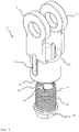
- Fig. 1 shows in an isometric view as an example of a cable sleeve 10 a fork or sheath sleeve (open spelter socket).
- the cable sleeve 10 is made in two parts and the two parts are hereinafter referred to as outer housing 12 (shown above) and inner housing 14 (shown axially below the outer housing 12).
- the outer housing 12 has at its upper end in the representation of the two fork ends 16.
- an eyelet In another cable sleeve 10 are here other contact means, so for example in a ⁇ senseilhülse (closed spelter socket) an eyelet. A usually provided for insertion into the holes in the fork ends 16 bolt is not shown.
- the outer housing 12 has an internal thread 18, which in the illustration in Fig. 1 because of the chosen perspective is not recognizable.
- the inner housing 14 in turn has an internal thread 18 matching external thread 20 and is thus a total detachably connectable to the outer housing 12 by it in the outer housing 12 can be screwed.
- Fig. 1 In the illustration in Fig. 1 is also seen that in the outer housing 12 between the fork ends 16 (or other rope sleeve 10 other contact means) and the internal thread 18, two holes 22, slots or other exemptions are formed, which are arranged radially opposite one another in the outer housing.
- the holes 22 are here slit-shaped and allow the passage of a pin, bolt or the like - hereinafter referred to as a pen.
- the holes 22 and inserted into the holes 22 pin (not shown) allow a rotationally fixed mounting of a screwed into the outer housing 12 inner housing 14 and prevent at least one full rotation of the inner housing 14 in the outer housing 12.
- the inner housing 14 at the upper edge of at least one footing 24, which here has an eyelet 26.
- the pin In the inserted state, the pin cooperates with at least one offset 24 in such a way that a full rotation of the inner housing 14 in the outer housing 12 is prevented by abutting from a certain rotational position of the inner housing 14, the shutdown 24 to the inserted into the holes 22 pin , If the or each shutdown 24 on the inner housing 14 is designed as an eyelet 26, a rotatability of the inner housing 14 in the outer housing 12 only in the scope of the opening width of the eyelet 26 is possible. If the opening width of the eyelet 26 is matched to a width of the holes 22 and corresponding to a diameter of the insertable into the holes 22 pin, the inner housing 14 is rotatably mounted in the outer housing 12.
- the pin can be secured captive on the outer housing 12 in a conventional manner - for example, secured by a split pin, a bracket or screwed onto a thread formed at the end of the pin nut. If two eyelets 26 are provided on the upper edge of the inner housing 14, a radially opposite position of the two eyelets 26 comes into consideration, so that the pin can be guided through the holes 22 and both eyelets 26.
- the inner housing 14 can thus be rotatably mounted after every half a revolution in the outer housing 12. In one embodiment of the inner housing 14 with more than two sheds 24 or eyelets 26 is an even finer adjustment of the screwing of the inner housing 14 in the internal thread 18 of the outer housing 12 is possible. With more than two stops / eyelets 24, 26 will provide a radially evenly spaced arrangement.
- the inner housing 14 has a form-fitting contour 28 for attaching a tool, for example an open-end wrench.
- the positive locking contour 28 allows the actuation or even the fixing of the inner housing 14, when the inner and outer housing 14, 12 are rotated relative to each other to make a length adjustment.
- the form-fitting contour 28, in particular for cable sleeves 10, for large loads, compared to the rest of the inner housing 14 may be made significantly larger than in Fig. 1 is shown to allow a fixation, for example, with a ferrule or the like, when a fixation with a hand tool, namely an open-end wrench, is no longer considered.
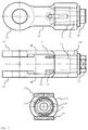
- Fig. 2 shows the rope sleeve Fig. 1 in the form of a wireframe representation, ie also with otherwise hidden lines. In this illustration, this is in Fig. 1 invisible internal thread 18 in the outer housing 12 clearly visible.
- Fig. 3 shows different views of the cable sleeve 10 Fig. 1 .
- the lower illustration in Fig. 3 is a sectional view along in the middle representation of Fig. 3 drawn section line AA.
- the inner housing 14 screwed into the outer housing 12, as far as it is hidden by the outer housing 12, is shown with dashed lines.
- the dashed lines not only show the outer contour of the inner housing 14, but also its inner contour.
- the inner housing 14 for receiving the cable end and for casting the cable end has a conical or at least partially conical inner volume 30, which has its smallest diameter at a provided for insertion of the cable end lower edge.
- a conical or at least to the lower edge of the inner housing 14 tapered contour of the inner volume 30 of the inner housing 14 is advantageous when it comes is to achieve the desired high breaking strength of the connection of the rope end with the cable sleeve 10, in this case the inner housing 14 of the cable sleeve 10.
- the particular contour of the inner volume 30 of the inner housing 14 is also in the lower illustration in Fig. 3 recognizable that, according to the sectional plane, a view into the cable sleeve 10 and the inner housing 14 and thereby a view into the downwardly tapered inner volume 30 of the inner housing 14.
- a rope end (not shown) inserted into this inner volume 30 can be cast in the inner volume 30 in a manner known per se (fixation with a potting medium) in order to achieve the permanent connection with the cable sleeve 10.
- the cable sleeve 10 is in three parts and includes an outer housing 12, an inner housing 14 and an intermediate housing. While at the in Fig. 1 As shown embodiment, the outer housing 12 had the female thread 18 for receiving the inner housing 14, this internal thread 18 is provided in a three-piece cable sleeve 10 in the intermediate housing.
- the intermediate housing is receivable by the outer housing 12 in an axially fixed position, as is known, for example, from so-called almost connector sockets.
Landscapes
- Engineering & Computer Science (AREA)
- General Engineering & Computer Science (AREA)
- Mechanical Engineering (AREA)
- Ropes Or Cables (AREA)
Description
Die Erfindung betrifft eine Seilendverbindung, insbesondere eine Seilendverbindung für Draht- oder Stahlseile. Seilendverbindungen sind zum Beispiel zur Kombination von Seilenden mit Gabel- oder Bügelseilhülsen (open spelter sockets), Ösenseilhülsen (closed spelter sockets) und dergleichen bekannt. Gabel- und Bügelseilhülsen und dergleichen werden im Folgenden zusammenfassend und ohne Verzicht auf eine weitergehende Allgemeingültigkeit kurz als Seilhülsen bezeichnet. Aus der
Bekannt ist eine Seilendverbindung, bei der das Seilende in einem auch als Seilbirne bezeichneten Ende einer Seilhülse vergossen wird. Damit die Verbindung genügend Zugfestigkeit besitzt, wird das Seilende nach dem Einführen in die Seilhülse aufgeflochten und die aufgeflochtenen Litzen des Seilendes werden in der Seilhülse mit einem Vergussmedium fixiert. Üblicherweise haben solche Seilhülsen ein konisches Innenvolumen, wobei an einem unteren, zur Einführung des Seils vorgesehenen Ende dieser Innenkonus seinen geringsten Durchmesser aufweist. Eine solche Seilendverbindung ist zum Beispiel aus der
Vergossene Seilhülsen zeichnen sich durch eine hohe Zugkraftbelastbarkeit aus und bei einer Überlastung eines Seils kommt es normalerweise eher zu einem Seilbruch als zu einem Ausreißen eines in einer Seilhülse vergossenen Seils aus der Seilhülse. Man spricht daher von einer Zugkraftbelastbarkeit dieser Seilendverbindungen von 100% der Bruchfestigkeit des Seils oder zumindest einer Zugkraftbelastbarkeit nahe 100% der Bruchfestigkeit des Seils.Potted cable sleeves are characterized by a high tensile load capacity and overloading a rope, it is usually more likely to a rope break than a tearing of a cast in a cable sheath rope from the cable sleeve. One therefore speaks of a tensile strength of these cable end connections of 100% of the breaking strength of the rope or at least a tensile load capacity close to 100% of the breaking strength of the rope.
Nachteilig bei bekannten Seilendverbindungen ist jedoch, dass sich Seile beim Gebrauch längen, speziell wenn ein Seil einer dynamischen Belastung ausgesetzt ist. Als dynamische Belastung wird dabei eine Belastung verstanden, die sich zum Beispiel beim mehrfachen Anheben und Absenken von Lasten ergibt oder wie sie sich ergibt, wenn Lasten pendeln. Eine besonders hohe dynamische Belastung ist gegeben, wenn die beiden vorgenannten Belastungsarten in Kombination auftreten.A disadvantage of known rope end connections, however, is that ropes lengthen in use, especially when a rope is subjected to dynamic loading. A dynamic load is understood to be a load resulting, for example, from the multiple lifting and lowering of loads or as it results when loads oscillate. A particularly high dynamic load is given if the two aforementioned load types occur in combination.
Als Seilendverbindungen sind auch sogenannte Keilendklemmen (open wedge sockets) bekannt. Diese weisen ein zur Aufnahme eines Keils vorgesehenes Gehäuse auf. Das Seil wird in das Gehäuse eingeführt, umläuft den Keil und das freie Ende des Seils wird an der Eintrittsseite wieder aus dem Gehäuse ausgeleitet. Bei Belastung des Seils pressen die auf das Seil einwirkenden Kräfte den Keil in das Gehäuse, so dass damit diese Seilverbindung zugbelastungsstabil wird.As cable end connections also so-called wedge end clamps (open wedge sockets) are known. These have a housing provided for receiving a wedge. The cable is inserted into the housing, runs around the wedge and the free end of the rope is discharged from the housing on the inlet side again. When the cable is loaded, the forces acting on the cable press the wedge into the housing, so that this cable connection is resistant to tensile stress.
Keilendklemmen haben den Vorteil, dass eine im Gebrauch erfolgte Längung des jeweiligen Seils kompensiert werden kann, indem das Seil in dem Gehäuse über den Keil nachgeführt wird und anschließend das Seilende wieder mit dem Keil fixiert wird. Allerdings wird das Seil in dem Gehäuse nicht nur einer Zugbelastung, sondern auch einer Druckbelastung ausgesetzt, so dass diese Seilendverbindung normalerweise nur eine Bruchkraft aufweist, die deutlich unter der Bruchkraft des Seils liegt. Üblich sind Bruchkräfte im Bereich von 80% der Bruchkraft des Seils.Wedge end clamps have the advantage that an elongation of the respective cable which has taken place in use can be compensated by guiding the cable in the housing over the wedge and then fixing the end of the cable again with the wedge. However, the rope is exposed in the housing not only a tensile load, but also a compressive load, so that this cable end connection normally has only a breaking force that is well below the breaking strength of the rope. Breaking forces in the range of 80% of the breaking force of the rope are usual.
Wünschenswert wäre demnach eine Seilendverbindung mit einerseits einer Bruchkraft im Bereich der Bruchkräfte, wie sie von vergossenen Seilendverbindungen bekannt sind, insbesondere mit einer Bruchkraft die über oder sogar deutlich über der Bruchkraft des Seils liegt, die anderseits eine Anpassung an eine eventuelle Längung des Seils erlaubt.It would therefore be desirable to have a cable end connection with, on the one hand, a breaking force in the area of the breaking forces, as known from molded cable end connections, in particular with a breaking force which is greater than or even significantly greater than the breaking force of the cable, which, on the other hand, permits adaptation to possible elongation of the cable.
Diese Aufgabe wird erfindungsgemäß mit einer Seilendhülse mit den Merkmalen des Anspruchs 1 gelöst. Dazu ist eine zumindest zweiteilige Seilendhülse mit einem äußeren Gehäuse und einem zur Aufnahme eines Seilendes vorgesehenen inneren Gehäuse vorgesehen, bei der mit dem inneren Gehäuse ein Seilende durch Vergießen des Seilendes im inneren Gehäuse verbindbar ist und bei der eine lösbare Verbindbarkeit des inneren Gehäuses mit dem äußeren Gehäuse eine Anpassung einer axialen Position des inneren Gehäuses im äußeren Gehäuse erlaubt.This object is achieved with a cable end sleeve with the features of claim 1. For this purpose, an at least two-part Seilendhülse is provided with an outer housing and a housing provided for receiving a cable end inner housing, in which with the inner housing, a cable end by casting the cable end in the inner housing is connectable and in a releasable Connectivity of the inner housing with the outer housing allows an adjustment of an axial position of the inner housing in the outer housing.
Aus der
Der Vorteil der Erfindung besteht darin, dass mit einer Anpassung einer axialen Position des inneren Gehäuses im äußeren Gehäuse eine Kompensation einer eventuellen Längung eines mit der Seilendhülse kombinierten Seils möglich ist. Wenn sich ein Seil zum Beispiel um fünf Millimeter gelängt hat, kann die axiale Position des inneren Gehäuses in Bezug auf das äußere Gehäuse so verstellt werden, dass eine Gesamtlänge von Seil und Seilendhülse wieder der ursprünglichen Gesamtlänge von Seil und Seilendhülse vor der Längung des Seils entspricht. Zum Erhalt einer ausreichenden Bruchfestigkeit ist dabei vorgesehen, dass das Seilende mit der Seilendhülse, nämlich deren innerem Gehäuse, durch Vergießen verbunden ist. Bei einer besonderen Ausführungsform ist dabei vorgesehen, dass das innere Gehäuse zur Aufnahme des Seilendes ein sich verjüngendes, insbesondere konisch geformtes Innenvolumen aufweist.The advantage of the invention is that with an adaptation of an axial position of the inner housing in the outer housing, a compensation of a possible elongation of a combined with the Seilendhülse rope is possible. For example, if a rope has lengthened by five millimeters, the axial position of the inner housing with respect to the outer housing may be adjusted so that a total length of the cable and end sleeve is equal to the original total length of the cable and end sleeve prior to elongation of the cable , To obtain a sufficient breaking strength it is provided that the cable end is connected to the cable end sleeve, namely the inner housing, by casting. In a particular embodiment, it is provided that the inner housing for receiving the cable end has a tapered, in particular conically shaped inner volume.
Vorteilhafte Ausgestaltungen der Erfindung sind Gegenstand der Unteransprüche. Dabei verwendete Rückbeziehungen weisen auf die weitere Ausbildung des Gegenstandes des Hauptanspruches durch die Merkmale des jeweiligen Unteranspruches hin; sie sind nicht als ein Verzicht auf die Erzielung eines selbständigen, gegenständlichen Schutzes für die Merkmalskombihationen der rückbezogenen Unteransprüche zu verstehen. Des Weiteren ist im Hinblick auf eine Auslegung der Ansprüche bei einer näheren Konkretisierung eines Merkmals in einem nachgeordneten Anspruch davon auszugehen, dass eine derartige Beschränkung in den jeweils vorangehenden Ansprüchen nicht vorhanden ist.]Advantageous embodiments of the invention are the subject of the dependent claims. This used backlinks point to the further development of the subject matter of the main claim by the features of the respective subclaim; they should not be construed as a waiver of the attainment of independent, objective protection for the feature combinations of the dependent claims. Furthermore, with a view to an interpretation of the claims in a more detailed specification of a feature in a subordinate claim, it should be assumed that such a restriction does not exist in the respective preceding claims.]
Bei der Seilendhülse ist die lösbare Verbindbarkeit und die Möglichkeit zur Anpassung einer axialen Position des inneren Gehäuses im äußeren Gehäuse realisiert, indem das innere Gehäuse ein Außengewinde und das äußere Gehäuse in einem zur Aufnahme des inneren Gehäuses vorgesehenen Bereich ein auf das Außengewinde abgestimmtes Innengewinde aufweist, so dass die axiale Position des inneren Gehäuses im äußeren Gehäuse durch Einschrauben des inneren Gehäuses in das äußere Gehäuse anpassbar ist. Der Vorteil besteht vor allem darin, dass das Zusammenwirken der beiden Gewindeteile (Innen- und Außengewinde) zur Aufnahme der zu erwartenden Kräfte gut geeignet sind. Zudem ist bei einem Gewinde eine besonders genaue Anpassung der axialen Position, abhängig von der jeweiligen Gewindesteigung möglich. Schließlich ist eine Anpassung einer axialen Position über ein Gewinde intuitiv bedienbar und lässt sich bei besonders großen und schweren Seilhülsen auch gut mit geeignetem Werkzeug unterstützen. Bei kleineren Seilendhülsen ist sogar auf rein manuellem Weg eine Anpassung der axialen Position möglich. Als Alternative zu einem Gewinde kommt eine im äußeren oder inneren Gehäuse gebildete Kulisse in Betracht, die zumindest abschnittsweise wie eine Formschlussaufnahme fungiert, wobei in solche Formschlussaufnahmen im inneren bzw. äußeren Gehäuse gebildete Formschlusselemente, zum Beispiel Abstellungen in Form von Zapfen, eingreifen. Ein Beispiel für eine solche Kulisse und korrespondierende Formschlusselemente ist eine Gestaltung, wie sie von einem Bajonettverschluss, insbesondere einem mehrstufigen Bajonettverschluss, bekannt ist. Zur Aufnahme größerer Kräfte, wie sie sich beim Heben von Lasten ohne Weiteres ergeben können, kann bei einer solchen Kulisse vorgesehen sein, dass ein bei einem Bajonettverschluss als Zapfen ausgebildetes Formschlusselement in Form eines Stegs ausgeführt ist, so dass anstelle einer punktförmigen Auflage- und Kraftübertragungsfläche die gesamte Länge des Stegs wirksam wird. Außerdem können mehrere Stege in jeweils eine Formschlussaufnahme eingeführt sein, so dass eine Mehrzahl von Stegen an der Kraftaufnahme/Kraftübertragung beteiligt ist. Die Stege und die Formschlussaufnahmen können eine Länge von bis zu der halben Umfangslinie des inneren Gehäuses aufweisen.In the cable end sleeve, the detachable connectivity and the possibility of adjusting an axial position of the inner housing in the outer housing is realized by the inner housing has an external thread and the outer housing in a provided for receiving the inner housing portion has a matched to the external thread internal thread, such that the axial position of the inner housing in the outer housing is adaptable by screwing the inner housing into the outer housing. Above all, the advantage consists in the fact that the interaction of the two threaded parts (internal and external threads) are well suited for absorbing the expected forces. In addition, with a thread, a particularly accurate adjustment of the axial position, depending on the respective thread pitch possible. Finally, an adaptation of an axial position via a thread can be operated intuitively and can also be supported well with suitable tools in the case of particularly large and heavy cable sleeves. For smaller cable end sleeves, an adjustment of the axial position is possible even by purely manual means. As an alternative to a thread formed in the outer or inner housing backdrop comes into consideration, which acts at least partially as a form-fitting, in such form-fitting recordings formed in the inner or outer housing interlocking elements, for example, stops in the form of pins, intervene. An example of such a link and corresponding interlocking elements is a design as it is known from a bayonet lock, in particular a multi-stage bayonet lock. To absorb larger forces, as in the case of Lifting of loads can easily result, may be provided in such a backdrop that a formed in a bayonet lock pin as form-fitting element is designed in the form of a web, so that instead of a point-shaped support and force transmission surface, the entire length of the web is effective. In addition, a plurality of webs may be introduced in each case a form-fitting receptacle, so that a plurality of webs is involved in the force absorption / power transmission. The webs and the form-fitting receptacles may have a length of up to half the circumferential line of the inner housing.
Wenn das äußere Gehäuse Bohrungen, Schlitze oder dergleichen zum Einführen eines Stifts und das innere Gehäuse an einer Oberkante ein oder mehrere Abstellungen aufweist, kann ein in eine Bohrung eingeführter oder ein oder durch zwei gegenüberliegende Bohrungen geführter Stift, Bolzen oder dergleichen im eingeführten Zustand mit jeweils zumindest einer Abstellung zusammenwirken, derart, dass der Stift bei einer Drehung des inneren Gehäuses im äußeren Gehäuse für die Abstellung oder jeweils zumindest eine Abstellung als Anschlag wirkt, so dass zumindest eine Vollumdrehung des inneren Gehäuses im äußeren Gehäuse verhindert ist. Die Drehbarkeit des inneren Gehäuses im äußeren Gehäuse ist damit begrenzt. Damit ist wirksam verhindert, dass eine vorgenommene Längenanpassung bei Benutzung der Seilendhülse/Seilendverbindung wieder verschwindet, indem sich das innere Gehäuse im äußeren Gehäuse dreht. Zudem ist sichergestellt, dass das innere Gehäuse nicht aus dem äußeren Gehäuse herausgedreht werden kann, und damit die Verbindung zwischen Seil und dem jeweiligen Kontaktmittel der Seilhülse, bei einer Bügelseilhülse also der am Ende befindlichen Öse, bei einer Gabelseilhülse den am Ende befindlichen Gabelenden mit einem dort einführbaren Bolzen, usw., abreißt. Dies würde nämlich, wenn mit der Seilverbindung/der Seilhülse eine Last bewegt wird, dazu führen, dass die Last nicht mehr oder nicht mehr vollständig gehalten wird.If the outer housing bores, slots or the like for insertion of a pin and the inner housing at an upper edge one or more Abstellungen, introduced into a bore or one or two opposing bores guided pin, bolt or the like in the inserted state with each cooperate at least one shutdown, such that the pin acts upon rotation of the inner housing in the outer housing for shutdown or each at least one stop as a stop, so that at least one full rotation of the inner housing in the outer housing is prevented. The rotatability of the inner housing in the outer housing is limited. This effectively prevents a length adjustment made when using the Seilendhülse / Seilendverbindung disappears by the inner housing rotates in the outer housing. In addition, it is ensured that the inner housing can not be unscrewed from the outer housing, and thus the connection between the cable and the respective contact means of the cable sleeve, with a Bügelseilhülse thus the eyelet located at the end, with a fork cable sleeve ends at the ends with a there insertable bolt, etc., breaks off. Namely, this would, if a load is moved with the cable connection / the cable sleeve, cause that the load is no longer or no longer completely held.
Insgesamt betrifft die Erfindung damit eine Seilendverbindung, bei der ein Draht- oder Stahlseil mit einer Seilhülse wie hier und nachfolgend beschrieben kombiniert ist. Zur Kombination des Seilendes mit der Seilhülse, nämlich deren innerem Gehäuse, ist bei einer Ausführungsform das Seilende im inneren Gehäuse der Seilhülse mit einem Vergussmedium fixiert.Overall, the invention thus relates to a cable end connection, in which a wire or steel cable is combined with a cable sleeve as described here and below. To combine the rope end with the rope sleeve, namely their inner housing, in one embodiment, the cable end is fixed in the inner housing of the cable sleeve with a potting medium.
Der Vorteil der Erfindung und ihrer Ausgestaltungen besteht insbesondere darin, dass zum Beispiel bei Kränen, bei denen die jeweilige Last gleichzeitig mit mehreren Seilen gehoben wird, wie dies zum Beispiel bei Portalkränen oder Portalhubwägen (van carrier) zum Ein- und Ausladen von Containern und dergleichen der Fall ist, eine im Betrieb auftretende ungleiche Längung der einzelnen Seile ausgeglichen werden kann. Ohne einen solchen Ausgleich der Längung würde sich eine Schieflage der jeweiligen Last ergeben, was zu Beschädigungen im Transportgut, aber auch zu Gefahrensituationen, zum Beispiel aufgrund einer ungleichen Belastung der einzelnen Seile führen kann.The advantage of the invention and its embodiments is in particular that, for example, in cranes in which the respective load is lifted simultaneously with several ropes, as for example in gantry cranes or gantry trucks (van carrier) for loading and unloading of containers and the like the case is that occurring in operation unequal elongation of the individual ropes can be compensated. Without such a compensation of the elongation, an imbalance of the respective load would result, which can lead to damage in the cargo, but also to dangerous situations, for example due to unequal loading of the individual ropes.
Die Erfindung betrifft damit auch eine Verwendung einer Seilendhülse der hier und im Folgenden beschriebenen Art oder eine Verwendung mehrerer derartiger Seilendhülsen zum Ausgleich einer beim Gebrauch vorkommenden Längung eines oder mehrerer Drahtseile. Konkrete Anwendungsfälle sind Portalkräne oder Portalhubwägen, bei denen die jeweilige Last mit zumindest vier synchron bewegten Seilen angehoben oder abgesenkt wird. Weitere Anwendungsfälle sind andere Kräne, bei denen die Last mit mehreren Seilen angehoben oder abgesenkt wird. Ein nochmals weiterer Anwendungsfall sind Schiffe, zum Beispiel Fähren, mit zumindest einem höhenverstellbaren Deck oder Zwischendeck. Ein solches Zwischendeck wird bei Fähren zum Beispiel angehoben, um eine maximale Höhe des jeweiligen Decks zu erreichen und damit die Aufnahme von Lastkraftwagen oder dergleichen zu ermöglichen. Wenn ein solches Zwischendeck abgesenkt wird, ergibt sich mit dem abgesenkten Zwischendeck in an sich bekannter Art und Weise eine zusätzliche Ladefläche. Das abgesenkte Zwischendeck erlaubt damit zum Beispiel das Aufnehme von Personenkraftwagen. Dann kann nämlich in einer ersten Ebene auf der Grundfläche des Decks eine Aufnahme von Fahrzeugen und in einer parallelen, zweiten Ebene auf der Grundfläche des Zwischendecks ebenfalls eine Aufnahme von Fahrzeugen erfolgen. Die Verwendung von vertikal beweglichen Zwischendecks ist selbstverständlich nicht auf Fähren und den Transport von Fahrzeugen beschränkt. Bei solchen vertikal beweglichen - also in ihrer Höhe im Schiff einstellbaren - Decks ist notwendig, dass die vertikale Positionierung sehr exakt erfolgt, damit das beweglichen Deck an allen Aufhängepunkten hängt und sich so einerseits eine gewünschte Ausrichtung des Decks, üblicherweise eine horizontale Ausrichtung, und andererseits eine gleichmäßige Lastverteilung ergibt. Alle beschriebenen Anwendungszenarien gehen von an mehreren Aufhängepunkten hängenden Lasten aus, zum Beispiel Containern, insbesondere einer Hubvorrichtung für Container (Topspreader), oder höhenverstellbaren Zwischendecks (Hängedecks). Indem zur Aufhängung solcher Lasten zumindest eine Seilhülse der hier und im Folgenden beschriebenen Art verwendet wird, ergibt sich nicht nur eine Möglichkeit, eventuelle Längenänderungen der verwendeten Drahtseile auszugleichen, sondern auch eine einfache Möglichkeit, eine gewünschte Ausrichtung der Last, üblicherweise eine horizontale Ausrichtung, sicherzustellen. Allgemein eignen sich die hier beschriebene Seilhülse und damit gebildete Seilendverbindungen für alle zumindest zweitrumigen Hebe- oder Fördereinrichtungen sowie für zumindest zweitrumige Verspannungen, etwa zur vertikalen Ausrichtung eines Mastes oder dergleichen, oder zumindest zweitrumige Halteseile und dergleichen.The invention thus also relates to a use of a cable end sleeve of the type described here and below or a use of a plurality of such cable end sleeves to compensate for a occurring during use elongation of one or more wire ropes. Specific applications are gantry cranes or gantry cranes, in which the respective load is raised or lowered with at least four synchronously moved ropes. Other applications include other cranes, where the load is raised or lowered with multiple ropes. Yet another use case are ships, for example ferries, with at least one height-adjustable deck or tween deck. Such an intermediate deck is raised in ferries, for example, to reach a maximum height of the respective deck and thus to allow the inclusion of trucks or the like. If such a tween deck is lowered, results in the lowered tiled deck in a conventional manner, an additional loading area. The lowered decks allow for example the pickup of passenger cars. Then, namely, in a first plane on the base of the deck a recording of vehicles and in a parallel, second plane on the base of the intermediate deck also take a recording of vehicles. Of course, the use of vertically moving intermediate decks is not limited to ferries and the transport of vehicles. In such vertically movable - so adjustable in height in the ship - Decks require vertical positioning to be very accurate, so that the mobile deck hangs from all suspension points, giving both a desired deck orientation, usually horizontal alignment, and a uniform load distribution. All described application scenarios assume loads suspended from several suspension points, for example containers, in particular a lifting device for containers (topspreaders) or height-adjustable intermediate decks (suspended ceilings). By using at least one cable sheath of the type described here and below for suspending such loads, not only is it possible to compensate for any changes in length of the wire ropes used, but also an easy way to ensure a desired alignment of the load, usually a horizontal orientation , In general, the cable sleeve described here and rope end connections formed therewith are suitable for all at least two-sided lifting or conveying devices and for at least two-third tension, for example for vertical alignment of a mast or the like, or at least two-strand tethers and the like.
Nachfolgend wird ein Ausführungsbeispiel der Erfindung anhand der Zeichnung näher erläutert. Einander entsprechende Gegenstände oder Elemente sind in allen Figuren mit den gleichen Bezugszeichen versehen. Das oder jedes Ausführungsbeispiel ist nicht als Einschränkung der Erfindung zu verstehen. Vielmehr sind im Rahmen der vorliegenden Offenbarung Abänderungen und Modifikationen möglich, die durch Kombination oder Abwandlung von einzelnen in Verbindung mit den im allgemeinen oder speziellen Beschreibungsteil beschriebenen sowie in den Ansprüchen und/oder der Zeichnung enthaltenen Merkmalen bzw. Elementen für den Fachmann im Hinblick auf die Lösung der Aufgabe entnehmbar sind und durch kombinierbare Merkmale zu einem neuen Gegenstand führen.An embodiment of the invention will be explained in more detail with reference to the drawing. Corresponding objects or elements are provided in all figures with the same reference numerals. The or each embodiment is not to be understood as limiting the invention. Rather, in the context of the present disclosure, modifications and modifications are possible by combining or modifying individual in combination with the described in the general or specific description part and in the claims and / or the drawings features or elements for the skilled in the art in view of Solution of the task can be removed and lead by combinable features to a new object.
- Fig. 1Fig. 1
- undand
- Fig. 2Fig. 2
- eine isometrische Darstellung einer Seilhülse sowiean isometric view of a rope sleeve as well
- Fig. 3Fig. 3
-
unterschiedliche Ansichten der Seilhülse aus
Fig. 1 .different views of the cable sleeveFig. 1 ,
An dem den Gabelenden 16 oder sonstigen Kontaktmitteln gegenüberliegenden Ende weist das äußere Gehäuse 12 ein Innengewinde 18 auf, das in der Darstellung in
In der Darstellung in
Bei einer Möglichkeit, einen Stift am äußeren Gehäuse 12 geeignet verliersicher zu halten, kommt auch eine Ausführungsform des äußeren Gehäuses 12 in Betracht, bei der anstelle der beiden im äußeren Gehäuse 12 radial gegenüberliegenden Bohrungen 22 nur eine Bohrung vorgesehen ist, durch die ein solcher Stift in das Innere des äußeren Gehäuses 12 einführbar ist und dort eine drehfeste Lagerung des inneren Gehäuses 14 bewirkt.In a way to hold a pin on the
Am seiner Unterkante weist das innere Gehäuse 14 eine Formschlusskontur 28 zum Ansetzen eines Werkzeugs, zum Beispiel eines Maulschlüssels, auf. Die Formschlusskontur 28 erlaubt das Betätigen oder auch nur das Fixieren des inneren Gehäuses 14, wenn inneres und äußeres Gehäuse 14, 12 relativ zueinander verdreht werden, um eine Längenanpassung vorzunehmen. Die Formschlusskontur 28 kann, insbesondere für Seilhülsen 10, für große Lasten, im Vergleich zum Rest des inneren Gehäuses 14 deutlich größer ausgeführt sein, als dies in
In den beiden oberen Darstellungen in
Die besondere Kontur des Innenvolumens 30 des inneren Gehäuses 14 ist auch in der unteren Darstellung in
Bei einer nicht dargestellten Ausführungsform ist die Seilhülse 10 dreiteilig und umfasst ein äußeres Gehäuse 12, ein inneres Gehäuse 14 und ein Zwischengehäuse. Während bei der in
Einzelne im Vordergrund stehende Aspekte der hier eingereichten Beschreibung lassen sich damit kurz wie folgt zusammenfassen: Angegeben werden eine Seilhülse 10 mit einem äußeren Gehäuse 12 und einem zur Aufnahme eines Seilendes vorgesehenen inneren Gehäuse 14, wobei eine lösbare Verbindbarkeit des inneren Gehäuses 14 mit dem äußeren Gehäuse 12 eine Anpassung einer axialen Position des inneren Gehäuses 14 im äußeren Gehäuse 12 erlaubt, sowie eine Seilendverbindung mit einer solchen Seilhülse 10. Bei einer besonderen Ausführungsform der Seilhülse 10 wird die Anpassung der axialen Position des inneren Gehäuses 14 in Bezug auf das äußere Gehäuse 12 und dessen Kontaktmittel, also zum Beispiel Gabelenden 16, dadurch realisiert, dass das innere Gehäuse 14 in das äußere Gehäuse 12 einschraubbar ist, so dass sich eine wirksame Lage eines Endpunkts eines mit dem inneren Gehäuse 14 verbindbaren oder verbundenen Seilendes in Bezug auf das jeweilige Kontaktmittel durch Ein- oder Ausschrauben des inneren Gehäuses 14, also jede Relativrotation des inneren Gehäuses 14 in Bezug auf das äußere Gehäuse 12, anpassen lässt.Individual aspects in the foreground of the description submitted here can thus be summarized briefly as follows: Specified are a
- 1010
- Seilhülsecable sleeve
- 1212
- äußeres Gehäuseouter casing
- 1414
- inneres Gehäuseinner casing
- 1616
- Gabelendefork end
- 1818
- Innengewinde (im äußeren Gehäuse)Internal thread (in the outer housing)
- 2020
- Außengewinde (am inneren Gehäuse)External thread (on the inner housing)
- 2222
- Bohrung (im äußeren Gehäuse)Bore (in outer housing)
- 2424
- Abstellung (am inneren Gehäuse)Shutdown (on the inner housing)
- 2626
- Öse (als Abstellung am inneren Gehäuse oder in einer Abstellung am inneren Gehäuse)Eyelet (as a stop on the inner housing or in a shutdown on the inner housing)
- 2828
- FormschlusskonturForm-fit contour
- 3030
- Innenvolumen (des inneren Gehäuses)Inner volume (of the inner housing)
Claims (8)
- A cable termination sleeve (10) having an outer housing (12) and an inner housing (14),
wherein the outer housing (12) comprises contact means (16) for raising, lowering or holding a load,
wherein the inner housing (14) is provided for receiving a cable termination, in that a cable termination can be connected with the inner housing (14) through socketing of the cable termination in the inner housing (14) and
wherein a releasable connectivity of the inner housing (14) with the outer housing (12) allows an adjustment of an axial position of the inner housing (14) in the outer housing (12) as well as a compensation of a possible elongation of a cable combined with the cable termination sleeve (10),
wherein the inner housing (14) has an external thread (20) and the outer housing (12) has an internal thread (18), which is matched to the external thread (20), in an area provided for receiving the inner housing (14),
wherein the axial position of the inner housing (14) in the outer housing (12) is adjustable by means of screwing the inner housing (14) into the outer housing (12), characterized in that
the outer housing (12) has at least one bore (22) in the form of an oblong hole for the insertion of a pin and the inner housing (14) has one or more stop mechanisms (24) or lugs (26) on an upper edge,
wherein the pin interacts in the inserted state respectively with at least one stop mechanism (24) or lug (26) in such a way that a complete revolution of the inner housing (14) in the outer housing (12) is prevented. - The cable termination sleeve (10) according to claim 1, wherein the inner housing (14) for receiving a cable termination has a conically shaped interior volume (30).
- The cable termination sleeve (10) according to one of claims 1 or 2, with an intermediate housing which can be received in an axially fixed position by the outer housing (12), wherein the intermediate housing comprises the inner thread (18) and wherein the axial position of the inner housing (14) in the outer housing (12) is adjustable by means of screwing the inner housing (14) into the intermediate housing.
- A cable termination connection, in which a wire or steel cable is combined with a cable termination sleeve (10) according to one of the preceding claims.
- The cable termination connection according to claim 4, wherein the cable termination is fixed in an inner housing (14) of the cable termination sleeve (10) with a socketing medium.
- A use of a cable termination sleeve (10)
having an outer and an inner housing (12, 14), wherein the outer housing (12) comprises contact means (16) for raising, lowering or holding a load, wherein a cable termination is fixed in the inner housing (14) by means of socketing and wherein a releasable connectivity of the inner housing (14) with the outer housing (12) allows an adjustment of an axial position of the inner housing (14) in the outer housing (12) as well as a compensation of a possible elongation of a cable combined with the cable termination sleeve (10), or
a cable termination sleeve (10) according to one of claims 1 to 3 or
a cable termination connection according to one of claims 4 or 5
for equalizing a change in length of one wire cable or a plurality of wire cables provided for raising or lowering a respective load. - The use of a cable termination sleeve (10) or a cable termination connection according to claim 6 in a straddle carrier or gantry crane for the transporting of containers, wherein a lifting device for the raising of containers hangs from at least two wire cables which are synchronous but move independently of one another and wherein at least one of the wire cables is fastened to such a cable termination sleeve (10) or such a cable termination connection.
- The use of a cable termination sleeve (10) or a cable termination connection according to claim 6 in a ship with at least one height-adjustable suspension deck, wherein the suspension deck hangs from a plurality of wire cables which are synchronous but move independently of one another and wherein at least one of the wire cables is fastened to such a cable termination sleeve (10) or such a cable termination connection.
Applications Claiming Priority (2)
| Application Number | Priority Date | Filing Date | Title |
|---|---|---|---|
| DE201220100161 DE202012100161U1 (en) | 2012-01-17 | 2012-01-17 | Rope end connection and cable sleeve for a rope end connection |
| PCT/EP2013/050530 WO2013107701A1 (en) | 2012-01-17 | 2013-01-13 | Cable end connection and cable socket for a cable end connection |
Publications (2)
| Publication Number | Publication Date |
|---|---|
| EP2805083A1 EP2805083A1 (en) | 2014-11-26 |
| EP2805083B1 true EP2805083B1 (en) | 2016-03-02 |
Family
ID=45923785
Family Applications (1)
| Application Number | Title | Priority Date | Filing Date |
|---|---|---|---|
| EP13701585.5A Active EP2805083B1 (en) | 2012-01-17 | 2013-01-13 | Cable end connection and cable socket for a cable end connection |
Country Status (3)
| Country | Link |
|---|---|
| EP (1) | EP2805083B1 (en) |
| DE (1) | DE202012100161U1 (en) |
| WO (1) | WO2013107701A1 (en) |
Cited By (3)
| Publication number | Priority date | Publication date | Assignee | Title |
|---|---|---|---|---|
| RU189375U1 (en) * | 2018-12-18 | 2019-05-21 | Публичное акционерное общество "Северсталь" (ПАО "Северсталь") | Guy |
| RU190219U1 (en) * | 2018-12-28 | 2019-06-24 | Публичное акционерное общество "Северсталь" (ПАО "Северсталь") | VAST |
| RU190332U1 (en) * | 2018-08-14 | 2019-06-26 | Публичное акционерное общество "Северсталь" (ПАО "Северсталь") | Guy |
Family Cites Families (8)
| Publication number | Priority date | Publication date | Assignee | Title |
|---|---|---|---|---|
| US853705A (en) | 1905-08-28 | 1907-05-14 | Columbus Brass Company | Flush-tank. |
| US985915A (en) | 1909-10-02 | 1911-03-07 | Louis Marchand Jr | Fastening for the ends of wire cables. |
| DE6801874U (en) | 1968-10-10 | 1969-02-06 | Atlas Mak Maschb Gmbh Fa | ROPE END PIECE. |
| CH608059A5 (en) * | 1976-02-09 | 1978-12-15 | Bureau Bbr Ltd | |
| GB2255354B (en) * | 1991-05-03 | 1994-09-28 | Bridon Plc | Strand anchorage |
| DE29811002U1 (en) | 1998-06-19 | 1998-09-24 | Nauti-Vela Gesellschaft für Yachtausrüstung mbH, 74909 Meckesheim | Fork terminal |
| US7536754B2 (en) * | 2005-01-14 | 2009-05-26 | Bright Technologies, Llc. | Swaged synthetic cable terminations |
| US8286309B2 (en) * | 2008-06-10 | 2012-10-16 | Actuant Corporation | Median barrier cable termination |
-
2012
- 2012-01-17 DE DE201220100161 patent/DE202012100161U1/en not_active Expired - Lifetime
-
2013
- 2013-01-13 WO PCT/EP2013/050530 patent/WO2013107701A1/en not_active Ceased
- 2013-01-13 EP EP13701585.5A patent/EP2805083B1/en active Active
Cited By (3)
| Publication number | Priority date | Publication date | Assignee | Title |
|---|---|---|---|---|
| RU190332U1 (en) * | 2018-08-14 | 2019-06-26 | Публичное акционерное общество "Северсталь" (ПАО "Северсталь") | Guy |
| RU189375U1 (en) * | 2018-12-18 | 2019-05-21 | Публичное акционерное общество "Северсталь" (ПАО "Северсталь") | Guy |
| RU190219U1 (en) * | 2018-12-28 | 2019-06-24 | Публичное акционерное общество "Северсталь" (ПАО "Северсталь") | VAST |
Also Published As
| Publication number | Publication date |
|---|---|
| DE202012100161U1 (en) | 2012-03-05 |
| EP2805083A1 (en) | 2014-11-26 |
| WO2013107701A1 (en) | 2013-07-25 |
Similar Documents
| Publication | Publication Date | Title |
|---|---|---|
| EP2388227B1 (en) | Crane hook with a hook weight assembly | |
| EP3499027B1 (en) | Assemblies for the transport of rotor blades of a wind turbine | |
| WO2012028470A1 (en) | Device for suspending a rail, in particular a rail of an overhead conveyor or lifting gear | |
| EP3165495B1 (en) | Rotating tower crane | |
| EP2805083B1 (en) | Cable end connection and cable socket for a cable end connection | |
| DE102015001619B4 (en) | Boom system for a mobile crane as well as a mobile crane | |
| DE29623539U1 (en) | Lift connection device | |
| EP1456559B1 (en) | Fastening means | |
| DE202016003698U1 (en) | mobile crane | |
| DE202012100953U1 (en) | Clamping screw, in particular for lashing containers on board ships | |
| DE202013101779U1 (en) | Extension means for a lashing device, in particular for lashing containers on board ships, and extension system and lashing system | |
| DE102015008989A1 (en) | Load handling devices | |
| EP0471325A1 (en) | Fixing device | |
| EP2851329A1 (en) | Modular crane erection winch | |
| EP2520535A1 (en) | Separable stop for a crane, in particular a mobile crane | |
| DE102022128717A1 (en) | HEIGHT SAFETY DEVICE FOR EASY COUPLING AND UNCOUPLING | |
| EP3246202B1 (en) | Lashing anchor | |
| DE102015116685B3 (en) | Chuck receiving means | |
| EP3650743A1 (en) | Attachment device | |
| DE102013214176B4 (en) | Lashing device for securing containers | |
| DE202019101238U1 (en) | cable end | |
| DE10019308B4 (en) | Suspension device for overhead lines | |
| DD291531A5 (en) | BOOMS WITH ONE DEVICE FOR ONE OR MULTIPLE TIPPABLE BOOM EXTENSIONS FOR CRANES, ESPECIALLY MOBILE CRANES | |
| DE804462C (en) | Clamping claw for hoists | |
| DE3538067C2 (en) |
Legal Events
| Date | Code | Title | Description |
|---|---|---|---|
| PUAI | Public reference made under article 153(3) epc to a published international application that has entered the european phase |
Free format text: ORIGINAL CODE: 0009012 |
|
| 17P | Request for examination filed |
Effective date: 20140718 |
|
| AK | Designated contracting states |
Kind code of ref document: A1 Designated state(s): AL AT BE BG CH CY CZ DE DK EE ES FI FR GB GR HR HU IE IS IT LI LT LU LV MC MK MT NL NO PL PT RO RS SE SI SK SM TR |
|
| DAX | Request for extension of the european patent (deleted) | ||
| GRAP | Despatch of communication of intention to grant a patent |
Free format text: ORIGINAL CODE: EPIDOSNIGR1 |
|
| INTG | Intention to grant announced |
Effective date: 20150924 |
|
| GRAS | Grant fee paid |
Free format text: ORIGINAL CODE: EPIDOSNIGR3 |
|
| GRAA | (expected) grant |
Free format text: ORIGINAL CODE: 0009210 |
|
| AK | Designated contracting states |
Kind code of ref document: B1 Designated state(s): AL AT BE BG CH CY CZ DE DK EE ES FI FR GB GR HR HU IE IS IT LI LT LU LV MC MK MT NL NO PL PT RO RS SE SI SK SM TR |
|
| REG | Reference to a national code |
Ref country code: GB Ref legal event code: FG4D Free format text: NOT ENGLISH |
|
| REG | Reference to a national code |
Ref country code: AT Ref legal event code: REF Ref document number: 778279 Country of ref document: AT Kind code of ref document: T Effective date: 20160315 Ref country code: CH Ref legal event code: EP |
|
| REG | Reference to a national code |
Ref country code: IE Ref legal event code: FG4D Free format text: LANGUAGE OF EP DOCUMENT: GERMAN |
|
| REG | Reference to a national code |
Ref country code: DE Ref legal event code: R096 Ref document number: 502013002051 Country of ref document: DE |
|
| REG | Reference to a national code |
Ref country code: NL Ref legal event code: FP |
|
| REG | Reference to a national code |
Ref country code: LT Ref legal event code: MG4D |
|
| PG25 | Lapsed in a contracting state [announced via postgrant information from national office to epo] |
Ref country code: GR Free format text: LAPSE BECAUSE OF FAILURE TO SUBMIT A TRANSLATION OF THE DESCRIPTION OR TO PAY THE FEE WITHIN THE PRESCRIBED TIME-LIMIT Effective date: 20160603 Ref country code: FI Free format text: LAPSE BECAUSE OF FAILURE TO SUBMIT A TRANSLATION OF THE DESCRIPTION OR TO PAY THE FEE WITHIN THE PRESCRIBED TIME-LIMIT Effective date: 20160302 Ref country code: NO Free format text: LAPSE BECAUSE OF FAILURE TO SUBMIT A TRANSLATION OF THE DESCRIPTION OR TO PAY THE FEE WITHIN THE PRESCRIBED TIME-LIMIT Effective date: 20160602 Ref country code: ES Free format text: LAPSE BECAUSE OF FAILURE TO SUBMIT A TRANSLATION OF THE DESCRIPTION OR TO PAY THE FEE WITHIN THE PRESCRIBED TIME-LIMIT Effective date: 20160302 Ref country code: HR Free format text: LAPSE BECAUSE OF FAILURE TO SUBMIT A TRANSLATION OF THE DESCRIPTION OR TO PAY THE FEE WITHIN THE PRESCRIBED TIME-LIMIT Effective date: 20160302 |
|
| PG25 | Lapsed in a contracting state [announced via postgrant information from national office to epo] |
Ref country code: LT Free format text: LAPSE BECAUSE OF FAILURE TO SUBMIT A TRANSLATION OF THE DESCRIPTION OR TO PAY THE FEE WITHIN THE PRESCRIBED TIME-LIMIT Effective date: 20160302 Ref country code: SE Free format text: LAPSE BECAUSE OF FAILURE TO SUBMIT A TRANSLATION OF THE DESCRIPTION OR TO PAY THE FEE WITHIN THE PRESCRIBED TIME-LIMIT Effective date: 20160302 Ref country code: LV Free format text: LAPSE BECAUSE OF FAILURE TO SUBMIT A TRANSLATION OF THE DESCRIPTION OR TO PAY THE FEE WITHIN THE PRESCRIBED TIME-LIMIT Effective date: 20160302 Ref country code: PL Free format text: LAPSE BECAUSE OF FAILURE TO SUBMIT A TRANSLATION OF THE DESCRIPTION OR TO PAY THE FEE WITHIN THE PRESCRIBED TIME-LIMIT Effective date: 20160302 Ref country code: RS Free format text: LAPSE BECAUSE OF FAILURE TO SUBMIT A TRANSLATION OF THE DESCRIPTION OR TO PAY THE FEE WITHIN THE PRESCRIBED TIME-LIMIT Effective date: 20160302 |
|
| PG25 | Lapsed in a contracting state [announced via postgrant information from national office to epo] |
Ref country code: EE Free format text: LAPSE BECAUSE OF FAILURE TO SUBMIT A TRANSLATION OF THE DESCRIPTION OR TO PAY THE FEE WITHIN THE PRESCRIBED TIME-LIMIT Effective date: 20160302 Ref country code: IS Free format text: LAPSE BECAUSE OF FAILURE TO SUBMIT A TRANSLATION OF THE DESCRIPTION OR TO PAY THE FEE WITHIN THE PRESCRIBED TIME-LIMIT Effective date: 20160702 |
|
| PG25 | Lapsed in a contracting state [announced via postgrant information from national office to epo] |
Ref country code: RO Free format text: LAPSE BECAUSE OF FAILURE TO SUBMIT A TRANSLATION OF THE DESCRIPTION OR TO PAY THE FEE WITHIN THE PRESCRIBED TIME-LIMIT Effective date: 20160302 Ref country code: SK Free format text: LAPSE BECAUSE OF FAILURE TO SUBMIT A TRANSLATION OF THE DESCRIPTION OR TO PAY THE FEE WITHIN THE PRESCRIBED TIME-LIMIT Effective date: 20160302 Ref country code: SM Free format text: LAPSE BECAUSE OF FAILURE TO SUBMIT A TRANSLATION OF THE DESCRIPTION OR TO PAY THE FEE WITHIN THE PRESCRIBED TIME-LIMIT Effective date: 20160302 Ref country code: CZ Free format text: LAPSE BECAUSE OF FAILURE TO SUBMIT A TRANSLATION OF THE DESCRIPTION OR TO PAY THE FEE WITHIN THE PRESCRIBED TIME-LIMIT Effective date: 20160302 Ref country code: PT Free format text: LAPSE BECAUSE OF FAILURE TO SUBMIT A TRANSLATION OF THE DESCRIPTION OR TO PAY THE FEE WITHIN THE PRESCRIBED TIME-LIMIT Effective date: 20160704 |
|
| REG | Reference to a national code |
Ref country code: DE Ref legal event code: R097 Ref document number: 502013002051 Country of ref document: DE |
|
| PG25 | Lapsed in a contracting state [announced via postgrant information from national office to epo] |
Ref country code: IT Free format text: LAPSE BECAUSE OF FAILURE TO SUBMIT A TRANSLATION OF THE DESCRIPTION OR TO PAY THE FEE WITHIN THE PRESCRIBED TIME-LIMIT Effective date: 20160302 |
|
| PLBE | No opposition filed within time limit |
Free format text: ORIGINAL CODE: 0009261 |
|
| STAA | Information on the status of an ep patent application or granted ep patent |
Free format text: STATUS: NO OPPOSITION FILED WITHIN TIME LIMIT |
|
| PG25 | Lapsed in a contracting state [announced via postgrant information from national office to epo] |
Ref country code: DK Free format text: LAPSE BECAUSE OF FAILURE TO SUBMIT A TRANSLATION OF THE DESCRIPTION OR TO PAY THE FEE WITHIN THE PRESCRIBED TIME-LIMIT Effective date: 20160302 |
|
| 26N | No opposition filed |
Effective date: 20161205 |
|
| PG25 | Lapsed in a contracting state [announced via postgrant information from national office to epo] |
Ref country code: BG Free format text: LAPSE BECAUSE OF FAILURE TO SUBMIT A TRANSLATION OF THE DESCRIPTION OR TO PAY THE FEE WITHIN THE PRESCRIBED TIME-LIMIT Effective date: 20160602 Ref country code: SI Free format text: LAPSE BECAUSE OF FAILURE TO SUBMIT A TRANSLATION OF THE DESCRIPTION OR TO PAY THE FEE WITHIN THE PRESCRIBED TIME-LIMIT Effective date: 20160302 |
|
| PG25 | Lapsed in a contracting state [announced via postgrant information from national office to epo] |
Ref country code: BE Free format text: LAPSE BECAUSE OF NON-PAYMENT OF DUE FEES Effective date: 20170131 |
|
| REG | Reference to a national code |
Ref country code: CH Ref legal event code: PL |
|
| GBPC | Gb: european patent ceased through non-payment of renewal fee |
Effective date: 20170113 |
|
| PG25 | Lapsed in a contracting state [announced via postgrant information from national office to epo] |
Ref country code: MC Free format text: LAPSE BECAUSE OF FAILURE TO SUBMIT A TRANSLATION OF THE DESCRIPTION OR TO PAY THE FEE WITHIN THE PRESCRIBED TIME-LIMIT Effective date: 20160302 |
|
| REG | Reference to a national code |
Ref country code: FR Ref legal event code: ST Effective date: 20170929 |
|
| PG25 | Lapsed in a contracting state [announced via postgrant information from national office to epo] |
Ref country code: LI Free format text: LAPSE BECAUSE OF NON-PAYMENT OF DUE FEES Effective date: 20170131 Ref country code: FR Free format text: LAPSE BECAUSE OF NON-PAYMENT OF DUE FEES Effective date: 20170131 Ref country code: CH Free format text: LAPSE BECAUSE OF NON-PAYMENT OF DUE FEES Effective date: 20170131 |
|
| REG | Reference to a national code |
Ref country code: IE Ref legal event code: MM4A |
|
| PG25 | Lapsed in a contracting state [announced via postgrant information from national office to epo] |
Ref country code: LU Free format text: LAPSE BECAUSE OF NON-PAYMENT OF DUE FEES Effective date: 20170113 Ref country code: GB Free format text: LAPSE BECAUSE OF NON-PAYMENT OF DUE FEES Effective date: 20170113 |
|
| REG | Reference to a national code |
Ref country code: BE Ref legal event code: MM Effective date: 20170131 |
|
| PG25 | Lapsed in a contracting state [announced via postgrant information from national office to epo] |
Ref country code: IE Free format text: LAPSE BECAUSE OF NON-PAYMENT OF DUE FEES Effective date: 20170113 |
|
| PG25 | Lapsed in a contracting state [announced via postgrant information from national office to epo] |
Ref country code: MT Free format text: LAPSE BECAUSE OF FAILURE TO SUBMIT A TRANSLATION OF THE DESCRIPTION OR TO PAY THE FEE WITHIN THE PRESCRIBED TIME-LIMIT Effective date: 20160302 |
|
| PG25 | Lapsed in a contracting state [announced via postgrant information from national office to epo] |
Ref country code: AL Free format text: LAPSE BECAUSE OF FAILURE TO SUBMIT A TRANSLATION OF THE DESCRIPTION OR TO PAY THE FEE WITHIN THE PRESCRIBED TIME-LIMIT Effective date: 20160302 |
|
| REG | Reference to a national code |
Ref country code: AT Ref legal event code: MM01 Ref document number: 778279 Country of ref document: AT Kind code of ref document: T Effective date: 20180113 |
|
| PG25 | Lapsed in a contracting state [announced via postgrant information from national office to epo] |
Ref country code: AT Free format text: LAPSE BECAUSE OF NON-PAYMENT OF DUE FEES Effective date: 20180113 |
|
| PG25 | Lapsed in a contracting state [announced via postgrant information from national office to epo] |
Ref country code: HU Free format text: LAPSE BECAUSE OF FAILURE TO SUBMIT A TRANSLATION OF THE DESCRIPTION OR TO PAY THE FEE WITHIN THE PRESCRIBED TIME-LIMIT; INVALID AB INITIO Effective date: 20130113 |
|
| PG25 | Lapsed in a contracting state [announced via postgrant information from national office to epo] |
Ref country code: CY Free format text: LAPSE BECAUSE OF FAILURE TO SUBMIT A TRANSLATION OF THE DESCRIPTION OR TO PAY THE FEE WITHIN THE PRESCRIBED TIME-LIMIT Effective date: 20160302 |
|
| PG25 | Lapsed in a contracting state [announced via postgrant information from national office to epo] |
Ref country code: MK Free format text: LAPSE BECAUSE OF FAILURE TO SUBMIT A TRANSLATION OF THE DESCRIPTION OR TO PAY THE FEE WITHIN THE PRESCRIBED TIME-LIMIT Effective date: 20160302 |
|
| PG25 | Lapsed in a contracting state [announced via postgrant information from national office to epo] |
Ref country code: TR Free format text: LAPSE BECAUSE OF FAILURE TO SUBMIT A TRANSLATION OF THE DESCRIPTION OR TO PAY THE FEE WITHIN THE PRESCRIBED TIME-LIMIT Effective date: 20160302 |
|
| PGFP | Annual fee paid to national office [announced via postgrant information from national office to epo] |
Ref country code: DE Payment date: 20241118 Year of fee payment: 13 |
|
| PGFP | Annual fee paid to national office [announced via postgrant information from national office to epo] |
Ref country code: NL Payment date: 20260116 Year of fee payment: 14 |