EP3245692B1 - Connecteur électrique avec un dispositif de compensation - Google Patents
Connecteur électrique avec un dispositif de compensation Download PDFInfo
- Publication number
- EP3245692B1 EP3245692B1 EP16700312.8A EP16700312A EP3245692B1 EP 3245692 B1 EP3245692 B1 EP 3245692B1 EP 16700312 A EP16700312 A EP 16700312A EP 3245692 B1 EP3245692 B1 EP 3245692B1
- Authority
- EP
- European Patent Office
- Prior art keywords
- connector part
- housing
- plug
- carrier element
- insertion direction
- Prior art date
- Legal status (The legal status is an assumption and is not a legal conclusion. Google has not performed a legal analysis and makes no representation as to the accuracy of the status listed.)
- Active
Links
- 230000013011 mating Effects 0.000 claims description 73
- 238000003780 insertion Methods 0.000 claims description 45
- 230000037431 insertion Effects 0.000 claims description 45
- 230000005489 elastic deformation Effects 0.000 claims description 4
- 229920001971 elastomer Polymers 0.000 claims description 3
- 239000000806 elastomer Substances 0.000 claims description 3
- 230000006835 compression Effects 0.000 description 3
- 238000007906 compression Methods 0.000 description 3
- 238000001514 detection method Methods 0.000 description 2
- 230000003287 optical effect Effects 0.000 description 2
- 230000005540 biological transmission Effects 0.000 description 1
- 238000006073 displacement reaction Methods 0.000 description 1
- 230000002349 favourable effect Effects 0.000 description 1
- 238000000034 method Methods 0.000 description 1
- 230000000284 resting effect Effects 0.000 description 1
- 230000001953 sensory effect Effects 0.000 description 1
Images


Classifications
-
- H—ELECTRICITY
- H01—ELECTRIC ELEMENTS
- H01R—ELECTRICALLY-CONDUCTIVE CONNECTIONS; STRUCTURAL ASSOCIATIONS OF A PLURALITY OF MUTUALLY-INSULATED ELECTRICAL CONNECTING ELEMENTS; COUPLING DEVICES; CURRENT COLLECTORS
- H01R13/00—Details of coupling devices of the kinds covered by groups H01R12/70 or H01R24/00 - H01R33/00
- H01R13/64—Means for preventing incorrect coupling
-
- H—ELECTRICITY
- H01—ELECTRIC ELEMENTS
- H01R—ELECTRICALLY-CONDUCTIVE CONNECTIONS; STRUCTURAL ASSOCIATIONS OF A PLURALITY OF MUTUALLY-INSULATED ELECTRICAL CONNECTING ELEMENTS; COUPLING DEVICES; CURRENT COLLECTORS
- H01R13/00—Details of coupling devices of the kinds covered by groups H01R12/70 or H01R24/00 - H01R33/00
- H01R13/62—Means for facilitating engagement or disengagement of coupling parts or for holding them in engagement
- H01R13/629—Additional means for facilitating engagement or disengagement of coupling parts, e.g. aligning or guiding means, levers, gas pressure electrical locking indicators, manufacturing tolerances
- H01R13/631—Additional means for facilitating engagement or disengagement of coupling parts, e.g. aligning or guiding means, levers, gas pressure electrical locking indicators, manufacturing tolerances for engagement only
- H01R13/6315—Additional means for facilitating engagement or disengagement of coupling parts, e.g. aligning or guiding means, levers, gas pressure electrical locking indicators, manufacturing tolerances for engagement only allowing relative movement between coupling parts, e.g. floating connection
-
- H—ELECTRICITY
- H01—ELECTRIC ELEMENTS
- H01R—ELECTRICALLY-CONDUCTIVE CONNECTIONS; STRUCTURAL ASSOCIATIONS OF A PLURALITY OF MUTUALLY-INSULATED ELECTRICAL CONNECTING ELEMENTS; COUPLING DEVICES; CURRENT COLLECTORS
- H01R13/00—Details of coupling devices of the kinds covered by groups H01R12/70 or H01R24/00 - H01R33/00
- H01R13/66—Structural association with built-in electrical component
- H01R13/70—Structural association with built-in electrical component with built-in switch
- H01R13/71—Contact members of coupling parts operating as switch, e.g. linear or rotational movement required after mechanical engagement of coupling part to establish electrical connection
-
- H—ELECTRICITY
- H01—ELECTRIC ELEMENTS
- H01R—ELECTRICALLY-CONDUCTIVE CONNECTIONS; STRUCTURAL ASSOCIATIONS OF A PLURALITY OF MUTUALLY-INSULATED ELECTRICAL CONNECTING ELEMENTS; COUPLING DEVICES; CURRENT COLLECTORS
- H01R31/00—Coupling parts supported only by co-operation with counterpart
- H01R31/06—Intermediate parts for linking two coupling parts, e.g. adapter
-
- H—ELECTRICITY
- H01—ELECTRIC ELEMENTS
- H01R—ELECTRICALLY-CONDUCTIVE CONNECTIONS; STRUCTURAL ASSOCIATIONS OF A PLURALITY OF MUTUALLY-INSULATED ELECTRICAL CONNECTING ELEMENTS; COUPLING DEVICES; CURRENT COLLECTORS
- H01R2201/00—Connectors or connections adapted for particular applications
- H01R2201/26—Connectors or connections adapted for particular applications for vehicles
Definitions
- the invention relates to a connector part according to the preamble of claim 1.
- Such a connector part comprises a plug housing which has at least one plug-in portion, which can be connected in a plug-in direction with a mating connector part for electrically contacting the connector part with the mating connector part.
- Such a connector part may be formed, for example, as a charging connector for electrically charging a battery of an electric vehicle.
- the connector part can be connected, for example via an electrical lead to a charging station and plugged into a charging socket of an electric vehicle, so that when connected connector part charging currents can be transferred from the charging station to the electric vehicle to charge in this way, the battery of the electric vehicle.
- the connector part is not manually attached to an associated mating connector part (on the side of the electric vehicle), but the connector part is automatically approximated using an electromechanical assembly the mating connector part and put in mating with the mating connector part into engagement.
- Such fully automatic or semi-automatic charging devices require that the position of the mating connector part on the vehicle with sufficient accuracy, for example, using an optical sensor is detected so that the connector part can be approximated in an automatic manner to the mating connector part and engaged with the mating connector part.
- a position detection is possible only with limited accuracy.
- an axle detection for axially parallel attachment of the connector part to the associated mating connector part is difficult.
- Such loads can also occur when there is a change in position of the vehicle relative to the charging station during a charging process, which may be associated with a change in position of the connector part relative to the mating connector part. Such changes in position may occur, for example, during loading and unloading of the vehicle and an associated lowering or raising of the vehicle.
- the contact carrier is arranged floating on a housing, so that position and angle deviations can be compensated for a plug-in connection with a mating connector part.
- Object of the present invention is to provide a connector part available that enables a simple, cost-effective way a reliable compensation of position and / or angular deviations from a desired position and a desired angle when attaching to an associated mating connector part.
- the connector part has a arranged on the plug housing compensation device, which has a housing, a connected to the plug housing, arranged on the housing support member and a support member with respect to the housing biasing spring element, wherein the support member with elastic deformation of the spring element relative to the housing is movable.
- the connector part thus has a plug housing and arranged on the plug housing compensation device.
- the plug housing is used for plug-in connection with an associated mating connector part and for this purpose has one or more plug-in sections, at which, for example, electrical contacts for electrical contacting with associated mating contacts can be arranged on the side of the mating connector part.
- the compensation device is used to compensate for deviations in the position and / or the angle at which the connector part is attached to the associated mating connector part, compared to a desired position and a desired angle.
- the connector part is to be set with its plug housing in a plug-in direction to the mating connector part, this (only) in a defined (desired) position at a defined (nominal) angle, namely aligned with the mating connector part, is possible. If, when applying the connector part to the mating connector part, there are deviations from this desired position and from this target angle, then these deviations can be compensated for by the compensation device.
- the carrier element is arranged with a disc-shaped base portion within an interior of the housing of the compensation device and thus enclosed by the housing.
- a pin element can extend from the base section in the direction of the plug-in housing, wherein this pin element engages through an opening in the housing of the compensation device and is connected to the plug-in housing at an end remote from the base section of the carrier element.
- the support member is thus held within the housing of the balancing device and thereby over the Spring element biased relative to the housing. If the position of the plug housing changes relative to the housing of the compensation device, then the base section of the support element moves within the housing, which is accompanied by a deformation of the spring element within the housing.
- the carrier element can move with its base portion within the housing, the opening of the housing, which is penetrated by the pin element of the carrier element, preferably larger than the lateral dimensions of the pin member, so that the pin member can move transversely to the insertion within the opening ,
- the carrier element is preferably fixed against rotation on the spring element.
- the carrier element is thus held in a defined position on the spring element and positioned via the spring element in the housing. Due to the carrier element biasing the housing relative to the spring element, the carrier element is held in a substantially non-deflected position relative to the housing when the connector part is not engaged with an associated mating connector part.
- the housing may, for example, be made in two parts from two housing parts to be attached to one another. On one of these housing parts, for example, in the direction of the plug-in direction in the interior of the housing projecting dome is formed, which serves to attach to the connector element when attaching the connector part to an associated mating connector part on the support member to sufficient insertion forces on the support member and on the plug housing for plug-in connection with the mating connector part to transmit.
- the dome In a non-deflected position in this case the dome is advantageously spaced from the carrier element and thus is not in contact with the carrier element. If the connector part is attached to an associated mating connector part, then the spring element is compressed axially along the insertion direction, resulting in that the dome comes into contact with a bearing surface of the support member and thus axial forces can be introduced into the support member.
- a holding device which is connected to the housing of the compensating device and introduces insertion forces into the housing of the compensating device, can thus press axially upon contact of the dome on the bearing surface of the carrier element on the carrier element and thus the plug housing, which is connected to the carrier element, bring into engagement with the associated mating connector part.
- the dome has an abutment surface which is designed in the shape of a spherical cap and which is to be brought into contact with the bearing surface of the carrier element. If the bearing surface of the carrier element also has a spherical cap shape, then the dome and the bearing surface of the carrier element together form a sliding bearing which enables pivoting of the carrier element relative to the housing while slidingly guiding the dome resting against the carrier element.
- the bearing surface of the support element and the contact surface of the dome which are both formed kugelkalottenförmig, have different radii. If the radius of the spherical cap bearing surface of the dome is smaller than the radius of the spherical cap bearing surface of the support member, the dome and the support member can pivot to each other and also laterally (transversely to the plug) are offset from each other, so that in a favorable manner position and angle deviations under investment the dome of the housing on the bearing surface of the support member and thus under axial force transmission from the housing of the compensating device can be compensated for the plug housing.
- the spring element may for example be made of plastic, for example a highly elastic elastomer.
- the spring element may, for example, have an annular basic shape and extend around the insertion direction in the interior of the housing of the compensation device.
- the support member may be biased in particular opposite to the insertion and transverse to the insertion relative to the housing, so that the support member against the insertion towards the direction of insertion of a bottom of the housing axially approximated dome and also laterally (transverse to the insertion) in the housing can be displaced under deformation of the spring element.
- the support element is preferably held positively on the spring element.
- the spring element for example, have a receiving portion which is annular and to which the carrier element can be attached, for example, with its base portion.
- a plurality of spring sections may extend in the manner of spring lips from this receiving section, wherein these spring sections extend radially, for example Insertion direction and axially along the insertion direction of the receiving portion extend and produce an elastic connection of the support member with the housing of the compensation device.
- the spring portions may extend annularly around the receiving portion.
- the spring sections are interrupted in the manner of segments in the circumferential direction to the insertion direction and thus form no closed rings.
- Fig. 1A, 1B show an embodiment of a connector part 1, which, as shown schematically in FIG Fig. 1B shown plugged with an associated mating connector part 4 in a plug-in direction E can be engaged.
- the connector part 1 may for example be part of a charging device and thus designed as a charging plug, which can be brought into engagement with an associated mating connector part 4 in the form of a charging socket to transmit charging currents, for example, between a charging station and an electric vehicle for charging batteries of the electric vehicle.
- the connector part 1 comprises a plug housing 2 with a housing portion 20, projecting from the plug portions 21, 22 in the insertion direction E.
- the plug-in section 21, 22 can be inserted into an insertion opening 40 of the mating connector part 4 in the plug-in direction E in order to electrically contact electrical contact elements 210, 220 arranged in this manner on the plug-in sections 21, 22 with associated mating contact elements of the mating connector part 4.
- the plug housing 2 Rearward of the plug portions 21, 22, the plug housing 2 is connected to a compensating device 3, which serves to compensate for positional deviations and angular deviations when attaching the connector part 1 to the mating connector part 4 and in this way a tilting of the Connector part 1 with its plug-in sections 21, 22 in the insertion opening 40 of the mating connector part 4 to prevent and reduce loads especially on the contact elements 210, 220.
- the compensating device 3 can act on an electromechanical holding device 5, which is connected via a connecting element 302 to a housing 30, 31 of the compensating device 3 and serves to automatically and mechanically control the connector part 1 Way to the mating connector part 4 to set and to bring this into engagement.
- Fig. 2A to 2C show a back view ( Fig. 2A ), a side view ( Fig. 2B ) and a front view ( Fig. 2C ) of the connector part 1.
- the compensation device 3 via a pin member 332 of a support member (to be described in detail below) connected to the housing portion 20 of the plug housing 2, wherein the position of the pin member 332 and above the plug housing 2 relative to the housing 30, 31 of the Compensation device 3 is variable and in this way deviations from a desired position and a desired angle when attaching the connector part 1 can be compensated to an associated mating connector part 4.
- Fig. 3A, 3B show perspective exploded views of the balancer 3, while Fig. 4 a sectional view taken along the line II-II according to Fig. 2A represents the balancing device 3.
- the compensation device 3 has a housing which is formed by housing parts 30, 31, which in the assembled state surround an interior space 310.
- a first housing part 30 in this case carries the connecting element 302 for connection to an (external) holding device 5, as shown schematically in FIG. 9.
- a second housing part 31 faces the plug housing 2 and in the assembled state is firmly connected to the first housing part 30.
- a spring element 32 is arranged, which is connected to a base portion 330 of a support member 33 and the support member 33 relative to the housing 30, 31 biases.
- the spring element 32 has an annular receiving portion 320, in which the carrier element 33 is inserted with its base portion 330, wherein form-fitting elements 334 in the form of projections on the base portion 330 of the support member 33 in Positive locking elements 325 engage in the form of recesses on the receiving portion 320 of the spring element 32 and in this way the support member 33 rotationally fixed to the spring element 32.
- a pin member 332 which passes through an opening 311 on the second housing part 31 and is connected via a connecting portion 333 fixed to the housing portion 20 of the plug housing 2.
- a dome 300 is formed, which projects in the direction of the insertion direction of the housing part 30 in the direction of the support member 33.
- the dome 300 has, on a side facing the carrier element 33, a contact surface 301 with a spherical cap shape which faces a likewise spherical cap bearing surface 331 on a side of the carrier element 33 facing the dome 300 and is designed to engage with the bearing surface 331 when the plug connector part 1 is inserted to get into the mating connector part 4 in Appendix.
- Fig. 4 As seen from the sectional view according to Fig. 4 can be seen in a non-deflected initial position, the support member 33 via the spring member 32 in a biased manner in the interior space 310 between the housing parts 30, 31 held. In this initial position, the dome 300 with its contact surface 301 is axially spaced along the insertion direction E of the bearing surface 331, so that the dome 300 is not in contact with the carrier element 33.
- the spherical cap-shaped contact surface 301 of the dome 300 and the spherical cap-shaped bearing surface 331 of the support member 33 different radii R1, R2.
- the radius R1 of the contact surface 301 is in this case smaller than the radius R2 of the bearing surface 331. This allows, as will be described below, a pivoting of the support member 33 relative to the dome 300 within the housing 30, 31 and also a lateral displacement transverse to the insertion direction E.
- the spring element 32 is resilient and made for example of a plastic, in particular an elastomer. Different embodiments of the spring element 32 are conceivable and possible.
- the spring element has an annular basic shape in which segmented spring sections 321-324 of the annular receiving section 320 extend in the manner of tabs.
- the spring sections 321-324 extend radially to the insertion direction E (spring sections 321, 322) or axially to the insertion direction E (spring sections 323, 324).
- the spring element 32 is held within the housing 30, 31 of the balancing device 3 by the spring portions 321-324 in abutment with the circumferential housing walls of the housing 30, 31 are.
- the spring element 32 can also be positively fixed within the housing 30, 31 and thus rotatably held by the insertion direction E in the housing 30, 31.
- the spring element 32 is configured with annular spring portions 321-324 which surround the annular receiving portion 320 circumferentially and are closed in the circumferential direction to the insertion direction E.
- the spring portions 321-324 extend substantially radially to the insertion direction E (spring portions 321, 322) or axially to the insertion direction E (spring portions 323, 324).
- the spring element 32 according to the embodiment according to Figs. 6A-6D can be defined via recesses 326 in the spring portion 321 positively within the housing 30, 31 of the balancing device 3 and thus rotatably held in the housing 30, 31.
- the compensation device 3 is, as I said, to compensate for deviations from a desired position and a desired angle when attaching the connector part 1 to an associated mating connector part 4. How this is done in accordance with the sectional views Figs. 7A to 7E illustrated.
- the support member 33 In a starting position prior to attachment of the connector part 1 to the associated mating connector part 4, the support member 33 is with its pin member 332 in an approximately central position at the opening 311 of the housing part 31 of the balancer 3. About the spring element 32, the support member 33 and about the with the support member 33 firmly connected plug housing 2 in position to the housing 30, 31 of the balancing device 3 held such that longitudinal axes L. (corresponding to the rotational symmetry axes) of the support member 33 and the dome 300 are aligned.
- the insertion of the connector part 1 with its plug sections 21, 22 in the associated mating connector part 4 causes the position of the plug housing 2 of the position of (stationary) mating connector part 4 adapts. Because only when the plug housing 2 is aligned with its plug portions 21, 22 with the mating connector part 4, an insertion into the mating connector part 4 is possible.
- the position of the plug housing 2 changes relative to the housing 30, 31 of the compensating device 3, which is held in position on the holding device 5.
- the plug housing 2 can move laterally in a direction B transversely to the insertion direction E relative to the housing 30, 31 ( Fig. 7C ) or in directions C, D relative to the housing 30, 31 of the balancing device 3 ( Fig. 7D, 7E ).
- FIGS. 7C-7E How out Figs. 7C-7E can be seen in these changes in position of the support member 33 in the housing 30, 31, the longitudinal axes L1, L2 of the dome 300 on the one hand and the support member 33 on the other not (more) with each other.
- the carrier element 33 can pivot relative to the dome 300, as shown in FIG Fig. 7D, 7E is shown. Because the radius R2 of the spherical-cap-shaped bearing surface 331 of the carrier element 33 is greater than the radius R1 of the spherical cap-shaped contact surface 301 of the mandrel 300, this pivoting can take place with a simultaneous lateral change in position of the carrier element 33 relative to the mandrel 300.
- the lateral movement of the carrier element 33 within the housing 30, 31 is limited by the opening 311 penetrated by the pin element 332 of the carrier element 33 in the housing part 31 of the compensation device 3 Fig. 7C and 7D shown. At maximum deflection, the pin element 332 comes into contact with the border of the opening 311, so that the lateral adjustability of the carrier element 33 in the housing 30, 31 is limited.
- a rotation of the plug housing 2 can be compensated for the insertion direction E. This is done under rotational deformation of the spring element 32, on the one hand rotatably held in the housing 30, 31 and on the other hand rotatably connected to the support member 33 and is thus subjected to torsional load of the plug housing 2 to torsion.
- the change in position of the support member 33 relative to the housing 30, 31 is always under deformation of the spring member 32. Does not load (more) between the plug housing 2 and the balancing device 3, so relaxes the spring element 32 and sets the carrier element 33 in its initial position ( Fig. 7A ) within the housing 30, 31 back.
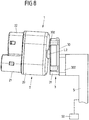
- Fig. 8 schematically shows a holding device 5, which is connected via the connecting element 302 with the housing 30, 31 of the balancing device 3 and serves to attach the connector part 1 semi-automatically or fully automatically to an associated mating connector part 4.
- the holding device 5 can be controlled, for example via a suitable control device 50, wherein the position of the mating connector part 4, for example, sensory, for example, using optical sensors can be detected to the connector part 1 automatically approach the mating connector part 4 and with the mating connector part 4 in engagement bring.
- one or more electrical lines can be led out of the housing 2, for example, by exiting the housing 2 laterally or upwards or downwards and being moved away from the housing 2, possibly around the compensating device 3. Several lines can also escape to different sides of the housing 2.
- the invention is not limited to use with charging plugs at charging stations or other charging devices, but can be used quite generally in connectors.
- the balancing device can be easily and inexpensively constructed and manufactured, allows a secure and reliable attachment of a connector part to a mating connector part and can provide a balance of positional deviations of a connector part when fitting to a mating connector part in an advantageous manner.
Claims (13)
- Élément connecteur enfichable (1), comportant un boîtier enfichable (20) pourvu d'au moins une partie enfichable (20, 21) qui peut être reliée, par enfichage dans une direction d'insertion (E), à un élément connecteur enfichable homologue (4), pour mettre l'élément connecteur enfichable (1) en contact électrique avec l'élément connecteur enfichable homologue (4), et un moyen de compensation (3) qui est disposé sur le boîtier enfichable (2) et qui comporte un boîtier (30, 31), un élément de support (33) qui est relié au boîtier enfichable (20) et qui est disposé sur le boîtier (30, 31) et un élément à ressort (32) qui précontraint l'élément de support (33) par rapport au boîtier (30, 31), dans lequel l'élément de support (33) est mobile par rapport au boîtier (30, 31) par déformation élastique de l'élément à ressort (32), dans lequel l'élément de support (33) est enfermé avec une partie de base (330) dans un espace interne (310) du boîtier (30, 31),
caractérisé en ce que l'élément de support (33) comporte un élément formant broche (332) qui est disposé sur la partie de base (330) et qui est en prise avec l'élément formant broche (332) à travers une ouverture (311) du boîtier (30, 31), dans lequel l'élément formant broche (332) est mobile dans l'ouverture (311) transversalement à la direction d'insertion (E). - Élément connecteur enfichable (1) selon la revendication 1, caractérisé en ce que l'élément de support (33) est fixé à l'élément à ressort (33) de manière fixe en rotation.
- Élément connecteur enfichable (1) selon la revendication 1 ou 2, caractérisé en ce que le boîtier (30, 31) est pourvu, sur une partie de boîtier (30), d'un dôme (300) qui fait saillie dans la direction d'insertion (E) et, par déformation élastique de l'élément à ressort (32), qui peut être amené en butée avec une surface d'appui (331) de l'élément de support (33), à des fins de transmission de force du boîtier (30, 31) vers l'élément de support (33) dans la direction d'insertion (E).
- Élément connecteur enfichable (1) selon la revendication 3, caractérisé en ce que le dôme (300) présente une surface d'appui en forme de calotte sphérique (301).
- Élément connecteur enfichable (1) selon la revendication 3 ou 4, caractérisé en ce que la surface d'appui (331) de l'élément de support (33) est en forme de calotte sphérique.
- Élément connecteur enfichable (1) selon la revendication 5, caractérisé en ce que la surface d'appui en forme de calotte sphérique (301) du dôme (300) présente un rayon (R1) inférieur à la surface d'appui en forme de calotte sphérique (331) de l'élément de support (33).
- Élément connecteur enfichable (1) selon l'une des revendications précédentes, caractérisé en ce que l'élément à ressort (32) est constitué d'un élastomère.
- Élément connecteur enfichable (1) selon l'une des revendications précédentes, caractérisé en ce que l'élément à ressort (32) précontraint l'élément de support (33) par rapport au boîtier (30, 31), de manière opposée à la direction d'insertion (E) et transversalement à la direction d'insertion (E).
- Élément connecteur enfichable (1) selon l'une des revendications précédentes, caractérisé en ce que l'élément à ressort (33) comporte une partie de réception (320) destinée à recevoir par complémentarité de forme l'élément de support (33).
- Élément connecteur enfichable (1) selon la revendication 9, caractérisé en ce que l'élément à ressort (32) comprend une pluralité de parties à ressorts (321-324) faisant saillie axialement dans la direction d'insertion (E) et/ou radialement par rapport à la direction d'insertion (E) depuis la partie de réception (320).
- Élément connecteur enfichable (1) selon la revendication 10, caractérisé en ce que les parties à ressorts (321-324) s'étendent de manière annulaire par rapport à la direction d'insertion (E).
- Élément connecteur enfichable (1) selon la revendication 10, caractérisé en ce que les parties à ressorts (321-324) sont interrompues dans la direction circonférentielle par rapport à la direction d'insertion (E).
- Élément connecteur enfichable (1) selon l'une des revendications précédentes, caractérisé en ce que le boîtier (30, 31) du moyen de compensation (3) peut être relié à un moyen de maintien (5) à des fins de positionnement automatique de l'élément connecteur enfichable (1).
Applications Claiming Priority (2)
| Application Number | Priority Date | Filing Date | Title |
|---|---|---|---|
| DE102015100452.6A DE102015100452A1 (de) | 2015-01-14 | 2015-01-14 | Steckverbinderteil mit einer Ausgleichseinrichtung |
| PCT/EP2016/050434 WO2016113238A1 (fr) | 2015-01-14 | 2016-01-12 | Élément de connecteur enfichable pourvu d'un moyen de compensation |
Publications (2)
| Publication Number | Publication Date |
|---|---|
| EP3245692A1 EP3245692A1 (fr) | 2017-11-22 |
| EP3245692B1 true EP3245692B1 (fr) | 2019-01-02 |
Family
ID=55083427
Family Applications (1)
| Application Number | Title | Priority Date | Filing Date |
|---|---|---|---|
| EP16700312.8A Active EP3245692B1 (fr) | 2015-01-14 | 2016-01-12 | Connecteur électrique avec un dispositif de compensation |
Country Status (5)
| Country | Link |
|---|---|
| US (1) | US10439328B2 (fr) |
| EP (1) | EP3245692B1 (fr) |
| CN (1) | CN107112693B (fr) |
| DE (1) | DE102015100452A1 (fr) |
| WO (1) | WO2016113238A1 (fr) |
Families Citing this family (2)
| Publication number | Priority date | Publication date | Assignee | Title |
|---|---|---|---|---|
| USD838906S1 (en) * | 2017-07-22 | 2019-01-22 | Helen Of Troy Limited | Adapter for a hair styling iron barrel |
| DE102019106747A1 (de) * | 2018-03-16 | 2019-09-19 | Hirschmann Automotive Gmbh | Steckverbindung insbesondere für ein Elektrofahrrad |
Family Cites Families (15)
| Publication number | Priority date | Publication date | Assignee | Title |
|---|---|---|---|---|
| US3609637A (en) * | 1969-12-01 | 1971-09-28 | Clyde C Cole | Electrical connector |
| US4030797A (en) * | 1975-06-11 | 1977-06-21 | International Telephone And Telegraph Corporation | Electrical connector |
| US4815986A (en) * | 1987-08-14 | 1989-03-28 | Lucas Weinschel, Inc. | Self-aligning blind mate connector |
| US5147221A (en) * | 1989-08-13 | 1992-09-15 | The Starling Manufacturing Company | Combination socket and wingless cable-end radio pin connector |
| FR2685825B1 (fr) * | 1991-12-26 | 1994-04-01 | Ecia | Connecteur automatique autocentrable. |
| FR2756428B1 (fr) * | 1996-11-27 | 1999-02-12 | Gobin Daude | Connecteur electrique pour vehicule automobile |
| FR2806540B1 (fr) * | 2000-03-20 | 2002-10-04 | Fci Jupiter | Fiche telemanipulable |
| FR2818450B1 (fr) * | 2000-12-20 | 2004-12-10 | Fci France | Fiche telemanipulable |
| US6390841B1 (en) * | 2001-04-25 | 2002-05-21 | Lear Corporation | Self-aligning electrical connector |
| NL1025379C2 (nl) * | 2004-02-02 | 2005-08-03 | Framatome Connectors Int | Optisch connectorsysteem. |
| ATE529927T1 (de) * | 2009-06-24 | 2011-11-15 | Coninvers Gmbh | Elektrischer push-pull-steckverbinder |
| DE102010035868B3 (de) | 2010-08-30 | 2012-02-16 | Phoenix Contact Gmbh & Co. Kg | Elektrische Komponente |
| CN103367979B (zh) * | 2012-04-05 | 2016-02-17 | 株式会社起家来人 | 连接器组件 |
| DE102012111408B3 (de) * | 2012-11-26 | 2013-10-24 | HARTING Electronics GmbH | Verriegelungsmechanismus für Steckverbinder |
| DE202014011301U1 (de) * | 2014-09-02 | 2019-02-15 | Phoenix Contact Gmbh & Co. Kg | Gehäuse zum Verbinden mit einem Steckverbinderteil |
-
2015
- 2015-01-14 DE DE102015100452.6A patent/DE102015100452A1/de not_active Ceased
-
2016
- 2016-01-12 EP EP16700312.8A patent/EP3245692B1/fr active Active
- 2016-01-12 CN CN201680005724.2A patent/CN107112693B/zh active Active
- 2016-01-12 US US15/542,943 patent/US10439328B2/en active Active
- 2016-01-12 WO PCT/EP2016/050434 patent/WO2016113238A1/fr active Application Filing
Non-Patent Citations (1)
| Title |
|---|
| None * |
Also Published As
| Publication number | Publication date |
|---|---|
| EP3245692A1 (fr) | 2017-11-22 |
| US10439328B2 (en) | 2019-10-08 |
| CN107112693B (zh) | 2019-08-13 |
| DE102015100452A1 (de) | 2016-07-14 |
| WO2016113238A1 (fr) | 2016-07-21 |
| CN107112693A (zh) | 2017-08-29 |
| US20180269631A1 (en) | 2018-09-20 |
Similar Documents
| Publication | Publication Date | Title |
|---|---|---|
| DE102014014536A1 (de) | Anschlussblock | |
| DE102015210336A1 (de) | Halteblock und modularer Steckereinsatz | |
| EP2045882B1 (fr) | Connecteur à fiche d'appareil à auto-ajustage | |
| WO2013060772A1 (fr) | Connecteur électrique enfichable en deux parties | |
| DE112017004526T5 (de) | Batterieanschlussverbinder | |
| EP3245692B1 (fr) | Connecteur électrique avec un dispositif de compensation | |
| WO2016079077A1 (fr) | Borne à ressort | |
| EP3639329B1 (fr) | Élément de connexion enfichable doté d'éléments de contact matés et son procédé de fabrication | |
| DE102019216266A1 (de) | Elektrisch betriebenes Fahrzeug mit einer wechselbaren Traktionsbatterie | |
| DE102019129436A1 (de) | Vorrichtung zum konduktiven Laden mit einem verbesserten Zentriermittel | |
| DE102017123704A1 (de) | Steckverbinderteil mit einem Verbindungselement zum Verbinden von Gehäuseteilen | |
| DE102017213941B4 (de) | Steckverbinder mit Kurzschlussklemme | |
| DE102017129429A1 (de) | Schneckengetriebe | |
| WO2002043191A1 (fr) | Dispositif de chargement | |
| DE102015106084A1 (de) | Vorrichtung zur automatisierten Montage eines Schalenelements an einem Pleuelelement | |
| EP1930990B1 (fr) | Connexion enfichable électrique | |
| DE4236794C2 (de) | Elektrische Steckverbindung | |
| EP4193220A1 (fr) | Module de caméra et procédé de production d'un module de caméra | |
| DE3838159C2 (de) | Einstellmechanismus für einen in einem Scheinwerfergehäuse verschwenkbar gelagerten Reflektor | |
| DE102018201648A1 (de) | Energiebereitstellungseinrichtung für ein Kraftfahrzeug, Verfahren zum Betreiben einer Energiebereitstellungseinrichtung, Kontaktiervorrichtung für ein Kraftfahrzeug sowie elektrisches Energiebereitstellungssystem für ein Kraftfahrzeug | |
| DE102018107886A1 (de) | Steckverbindersystem mit einem bistabilen Element | |
| EP2385206A2 (fr) | Agencement de commutation | |
| DE102010032663A1 (de) | Leitungsanbindung | |
| DE102008054964A1 (de) | Kontaktierungsstecker sowie Kontaktierungssteckverbindung | |
| DE102009047221A1 (de) | Kontaktierungsstecker sowie Kontaktierungsverbindung |
Legal Events
| Date | Code | Title | Description |
|---|---|---|---|
| STAA | Information on the status of an ep patent application or granted ep patent |
Free format text: STATUS: THE INTERNATIONAL PUBLICATION HAS BEEN MADE |
|
| PUAI | Public reference made under article 153(3) epc to a published international application that has entered the european phase |
Free format text: ORIGINAL CODE: 0009012 |
|
| STAA | Information on the status of an ep patent application or granted ep patent |
Free format text: STATUS: REQUEST FOR EXAMINATION WAS MADE |
|
| 17P | Request for examination filed |
Effective date: 20170712 |
|
| AK | Designated contracting states |
Kind code of ref document: A1 Designated state(s): AL AT BE BG CH CY CZ DE DK EE ES FI FR GB GR HR HU IE IS IT LI LT LU LV MC MK MT NL NO PL PT RO RS SE SI SK SM TR |
|
| AX | Request for extension of the european patent |
Extension state: BA ME |
|
| DAV | Request for validation of the european patent (deleted) | ||
| DAX | Request for extension of the european patent (deleted) | ||
| GRAP | Despatch of communication of intention to grant a patent |
Free format text: ORIGINAL CODE: EPIDOSNIGR1 |
|
| STAA | Information on the status of an ep patent application or granted ep patent |
Free format text: STATUS: GRANT OF PATENT IS INTENDED |
|
| INTG | Intention to grant announced |
Effective date: 20180727 |
|
| RIC1 | Information provided on ipc code assigned before grant |
Ipc: H01R 13/631 20060101ALI20180713BHEP Ipc: H01R 13/64 20060101ALI20180713BHEP Ipc: H01R 13/71 20060101AFI20180713BHEP |
|
| RIN1 | Information on inventor provided before grant (corrected) |
Inventor name: FUEHRER, THOMAS Inventor name: BABEZKI, ROBERT |
|
| GRAS | Grant fee paid |
Free format text: ORIGINAL CODE: EPIDOSNIGR3 |
|
| GRAA | (expected) grant |
Free format text: ORIGINAL CODE: 0009210 |
|
| STAA | Information on the status of an ep patent application or granted ep patent |
Free format text: STATUS: THE PATENT HAS BEEN GRANTED |
|
| AK | Designated contracting states |
Kind code of ref document: B1 Designated state(s): AL AT BE BG CH CY CZ DE DK EE ES FI FR GB GR HR HU IE IS IT LI LT LU LV MC MK MT NL NO PL PT RO RS SE SI SK SM TR |
|
| REG | Reference to a national code |
Ref country code: GB Ref legal event code: FG4D Free format text: NOT ENGLISH |
|
| REG | Reference to a national code |
Ref country code: CH Ref legal event code: EP Ref country code: AT Ref legal event code: REF Ref document number: 1085609 Country of ref document: AT Kind code of ref document: T Effective date: 20190115 |
|
| REG | Reference to a national code |
Ref country code: IE Ref legal event code: FG4D Free format text: LANGUAGE OF EP DOCUMENT: GERMAN |
|
| REG | Reference to a national code |
Ref country code: DE Ref legal event code: R096 Ref document number: 502016003068 Country of ref document: DE |
|
| REG | Reference to a national code |
Ref country code: NL Ref legal event code: MP Effective date: 20190102 |
|
| REG | Reference to a national code |
Ref country code: LT Ref legal event code: MG4D |
|
| PG25 | Lapsed in a contracting state [announced via postgrant information from national office to epo] |
Ref country code: NL Free format text: LAPSE BECAUSE OF FAILURE TO SUBMIT A TRANSLATION OF THE DESCRIPTION OR TO PAY THE FEE WITHIN THE PRESCRIBED TIME-LIMIT Effective date: 20190102 |
|
| PG25 | Lapsed in a contracting state [announced via postgrant information from national office to epo] |
Ref country code: SE Free format text: LAPSE BECAUSE OF FAILURE TO SUBMIT A TRANSLATION OF THE DESCRIPTION OR TO PAY THE FEE WITHIN THE PRESCRIBED TIME-LIMIT Effective date: 20190102 Ref country code: LT Free format text: LAPSE BECAUSE OF FAILURE TO SUBMIT A TRANSLATION OF THE DESCRIPTION OR TO PAY THE FEE WITHIN THE PRESCRIBED TIME-LIMIT Effective date: 20190102 Ref country code: FI Free format text: LAPSE BECAUSE OF FAILURE TO SUBMIT A TRANSLATION OF THE DESCRIPTION OR TO PAY THE FEE WITHIN THE PRESCRIBED TIME-LIMIT Effective date: 20190102 Ref country code: PT Free format text: LAPSE BECAUSE OF FAILURE TO SUBMIT A TRANSLATION OF THE DESCRIPTION OR TO PAY THE FEE WITHIN THE PRESCRIBED TIME-LIMIT Effective date: 20190502 Ref country code: ES Free format text: LAPSE BECAUSE OF FAILURE TO SUBMIT A TRANSLATION OF THE DESCRIPTION OR TO PAY THE FEE WITHIN THE PRESCRIBED TIME-LIMIT Effective date: 20190102 Ref country code: NO Free format text: LAPSE BECAUSE OF FAILURE TO SUBMIT A TRANSLATION OF THE DESCRIPTION OR TO PAY THE FEE WITHIN THE PRESCRIBED TIME-LIMIT Effective date: 20190402 Ref country code: PL Free format text: LAPSE BECAUSE OF FAILURE TO SUBMIT A TRANSLATION OF THE DESCRIPTION OR TO PAY THE FEE WITHIN THE PRESCRIBED TIME-LIMIT Effective date: 20190102 |
|
| PG25 | Lapsed in a contracting state [announced via postgrant information from national office to epo] |
Ref country code: IS Free format text: LAPSE BECAUSE OF FAILURE TO SUBMIT A TRANSLATION OF THE DESCRIPTION OR TO PAY THE FEE WITHIN THE PRESCRIBED TIME-LIMIT Effective date: 20190502 Ref country code: LV Free format text: LAPSE BECAUSE OF FAILURE TO SUBMIT A TRANSLATION OF THE DESCRIPTION OR TO PAY THE FEE WITHIN THE PRESCRIBED TIME-LIMIT Effective date: 20190102 Ref country code: GR Free format text: LAPSE BECAUSE OF FAILURE TO SUBMIT A TRANSLATION OF THE DESCRIPTION OR TO PAY THE FEE WITHIN THE PRESCRIBED TIME-LIMIT Effective date: 20190403 Ref country code: HR Free format text: LAPSE BECAUSE OF FAILURE TO SUBMIT A TRANSLATION OF THE DESCRIPTION OR TO PAY THE FEE WITHIN THE PRESCRIBED TIME-LIMIT Effective date: 20190102 Ref country code: RS Free format text: LAPSE BECAUSE OF FAILURE TO SUBMIT A TRANSLATION OF THE DESCRIPTION OR TO PAY THE FEE WITHIN THE PRESCRIBED TIME-LIMIT Effective date: 20190102 Ref country code: BG Free format text: LAPSE BECAUSE OF FAILURE TO SUBMIT A TRANSLATION OF THE DESCRIPTION OR TO PAY THE FEE WITHIN THE PRESCRIBED TIME-LIMIT Effective date: 20190402 |
|
| REG | Reference to a national code |
Ref country code: CH Ref legal event code: PL |
|
| PG25 | Lapsed in a contracting state [announced via postgrant information from national office to epo] |
Ref country code: LU Free format text: LAPSE BECAUSE OF NON-PAYMENT OF DUE FEES Effective date: 20190112 |
|
| REG | Reference to a national code |
Ref country code: DE Ref legal event code: R097 Ref document number: 502016003068 Country of ref document: DE |
|
| REG | Reference to a national code |
Ref country code: BE Ref legal event code: MM Effective date: 20190131 |
|
| REG | Reference to a national code |
Ref country code: IE Ref legal event code: MM4A |
|
| PG25 | Lapsed in a contracting state [announced via postgrant information from national office to epo] |
Ref country code: AL Free format text: LAPSE BECAUSE OF FAILURE TO SUBMIT A TRANSLATION OF THE DESCRIPTION OR TO PAY THE FEE WITHIN THE PRESCRIBED TIME-LIMIT Effective date: 20190102 Ref country code: MC Free format text: LAPSE BECAUSE OF FAILURE TO SUBMIT A TRANSLATION OF THE DESCRIPTION OR TO PAY THE FEE WITHIN THE PRESCRIBED TIME-LIMIT Effective date: 20190102 Ref country code: RO Free format text: LAPSE BECAUSE OF FAILURE TO SUBMIT A TRANSLATION OF THE DESCRIPTION OR TO PAY THE FEE WITHIN THE PRESCRIBED TIME-LIMIT Effective date: 20190102 Ref country code: CZ Free format text: LAPSE BECAUSE OF FAILURE TO SUBMIT A TRANSLATION OF THE DESCRIPTION OR TO PAY THE FEE WITHIN THE PRESCRIBED TIME-LIMIT Effective date: 20190102 Ref country code: EE Free format text: LAPSE BECAUSE OF FAILURE TO SUBMIT A TRANSLATION OF THE DESCRIPTION OR TO PAY THE FEE WITHIN THE PRESCRIBED TIME-LIMIT Effective date: 20190102 Ref country code: IT Free format text: LAPSE BECAUSE OF FAILURE TO SUBMIT A TRANSLATION OF THE DESCRIPTION OR TO PAY THE FEE WITHIN THE PRESCRIBED TIME-LIMIT Effective date: 20190102 Ref country code: SK Free format text: LAPSE BECAUSE OF FAILURE TO SUBMIT A TRANSLATION OF THE DESCRIPTION OR TO PAY THE FEE WITHIN THE PRESCRIBED TIME-LIMIT Effective date: 20190102 Ref country code: DK Free format text: LAPSE BECAUSE OF FAILURE TO SUBMIT A TRANSLATION OF THE DESCRIPTION OR TO PAY THE FEE WITHIN THE PRESCRIBED TIME-LIMIT Effective date: 20190102 |
|
| PLBE | No opposition filed within time limit |
Free format text: ORIGINAL CODE: 0009261 |
|
| STAA | Information on the status of an ep patent application or granted ep patent |
Free format text: STATUS: NO OPPOSITION FILED WITHIN TIME LIMIT |
|
| PG25 | Lapsed in a contracting state [announced via postgrant information from national office to epo] |
Ref country code: BE Free format text: LAPSE BECAUSE OF NON-PAYMENT OF DUE FEES Effective date: 20190131 Ref country code: SM Free format text: LAPSE BECAUSE OF FAILURE TO SUBMIT A TRANSLATION OF THE DESCRIPTION OR TO PAY THE FEE WITHIN THE PRESCRIBED TIME-LIMIT Effective date: 20190102 |
|
| 26N | No opposition filed |
Effective date: 20191003 |
|
| PG25 | Lapsed in a contracting state [announced via postgrant information from national office to epo] |
Ref country code: LI Free format text: LAPSE BECAUSE OF NON-PAYMENT OF DUE FEES Effective date: 20190131 Ref country code: CH Free format text: LAPSE BECAUSE OF NON-PAYMENT OF DUE FEES Effective date: 20190131 |
|
| PG25 | Lapsed in a contracting state [announced via postgrant information from national office to epo] |
Ref country code: IE Free format text: LAPSE BECAUSE OF NON-PAYMENT OF DUE FEES Effective date: 20190112 |
|
| PG25 | Lapsed in a contracting state [announced via postgrant information from national office to epo] |
Ref country code: FR Free format text: LAPSE BECAUSE OF NON-PAYMENT OF DUE FEES Effective date: 20190302 Ref country code: SI Free format text: LAPSE BECAUSE OF FAILURE TO SUBMIT A TRANSLATION OF THE DESCRIPTION OR TO PAY THE FEE WITHIN THE PRESCRIBED TIME-LIMIT Effective date: 20190102 |
|
| PG25 | Lapsed in a contracting state [announced via postgrant information from national office to epo] |
Ref country code: TR Free format text: LAPSE BECAUSE OF FAILURE TO SUBMIT A TRANSLATION OF THE DESCRIPTION OR TO PAY THE FEE WITHIN THE PRESCRIBED TIME-LIMIT Effective date: 20190102 |
|
| PG25 | Lapsed in a contracting state [announced via postgrant information from national office to epo] |
Ref country code: MT Free format text: LAPSE BECAUSE OF FAILURE TO SUBMIT A TRANSLATION OF THE DESCRIPTION OR TO PAY THE FEE WITHIN THE PRESCRIBED TIME-LIMIT Effective date: 20190102 |
|
| GBPC | Gb: european patent ceased through non-payment of renewal fee |
Effective date: 20200112 |
|
| PG25 | Lapsed in a contracting state [announced via postgrant information from national office to epo] |
Ref country code: GB Free format text: LAPSE BECAUSE OF NON-PAYMENT OF DUE FEES Effective date: 20200112 |
|
| PG25 | Lapsed in a contracting state [announced via postgrant information from national office to epo] |
Ref country code: CY Free format text: LAPSE BECAUSE OF FAILURE TO SUBMIT A TRANSLATION OF THE DESCRIPTION OR TO PAY THE FEE WITHIN THE PRESCRIBED TIME-LIMIT Effective date: 20190102 |
|
| PG25 | Lapsed in a contracting state [announced via postgrant information from national office to epo] |
Ref country code: HU Free format text: LAPSE BECAUSE OF FAILURE TO SUBMIT A TRANSLATION OF THE DESCRIPTION OR TO PAY THE FEE WITHIN THE PRESCRIBED TIME-LIMIT; INVALID AB INITIO Effective date: 20160112 |
|
| REG | Reference to a national code |
Ref country code: AT Ref legal event code: MM01 Ref document number: 1085609 Country of ref document: AT Kind code of ref document: T Effective date: 20210112 |
|
| PG25 | Lapsed in a contracting state [announced via postgrant information from national office to epo] |
Ref country code: AT Free format text: LAPSE BECAUSE OF NON-PAYMENT OF DUE FEES Effective date: 20210112 |
|
| PG25 | Lapsed in a contracting state [announced via postgrant information from national office to epo] |
Ref country code: MK Free format text: LAPSE BECAUSE OF FAILURE TO SUBMIT A TRANSLATION OF THE DESCRIPTION OR TO PAY THE FEE WITHIN THE PRESCRIBED TIME-LIMIT Effective date: 20190102 |
|
| P01 | Opt-out of the competence of the unified patent court (upc) registered |
Effective date: 20230525 |
|
| P02 | Opt-out of the competence of the unified patent court (upc) changed |
Effective date: 20230530 |
|
| PGFP | Annual fee paid to national office [announced via postgrant information from national office to epo] |
Ref country code: DE Payment date: 20240328 Year of fee payment: 9 |