EP3243572B1 - Erkennungsvorrichtung für oszillationsgeschwindigkeit - Google Patents
Erkennungsvorrichtung für oszillationsgeschwindigkeit Download PDFInfo
- Publication number
- EP3243572B1 EP3243572B1 EP17161532.1A EP17161532A EP3243572B1 EP 3243572 B1 EP3243572 B1 EP 3243572B1 EP 17161532 A EP17161532 A EP 17161532A EP 3243572 B1 EP3243572 B1 EP 3243572B1
- Authority
- EP
- European Patent Office
- Prior art keywords
- oscillating
- ultrasonic transducer
- digital
- velocity
- coefficient
- Prior art date
- Legal status (The legal status is an assumption and is not a legal conclusion. Google has not performed a legal analysis and makes no representation as to the accuracy of the status listed.)
- Active
Links
- 238000005070 sampling Methods 0.000 claims description 21
- 230000010355 oscillation Effects 0.000 claims description 20
- 238000000034 method Methods 0.000 claims description 17
- 238000006243 chemical reaction Methods 0.000 claims description 16
- 238000004088 simulation Methods 0.000 description 6
- 238000004891 communication Methods 0.000 description 4
- 230000003111 delayed effect Effects 0.000 description 4
- 230000000694 effects Effects 0.000 description 4
- 238000004506 ultrasonic cleaning Methods 0.000 description 4
- 238000010586 diagram Methods 0.000 description 3
- 238000004140 cleaning Methods 0.000 description 2
- 238000005520 cutting process Methods 0.000 description 2
- 230000001804 emulsifying effect Effects 0.000 description 2
- 238000005304 joining Methods 0.000 description 2
- 239000007788 liquid Substances 0.000 description 2
- 238000004519 manufacturing process Methods 0.000 description 2
- 239000002184 metal Substances 0.000 description 2
- 238000012544 monitoring process Methods 0.000 description 2
- 239000007787 solid Substances 0.000 description 2
- 239000000126 substance Substances 0.000 description 2
- 230000001133 acceleration Effects 0.000 description 1
- 230000003213 activating effect Effects 0.000 description 1
- 230000006978 adaptation Effects 0.000 description 1
- 230000003247 decreasing effect Effects 0.000 description 1
- 230000007547 defect Effects 0.000 description 1
- 230000006866 deterioration Effects 0.000 description 1
- 238000006073 displacement reaction Methods 0.000 description 1
- 239000004973 liquid crystal related substance Substances 0.000 description 1
- 239000000463 material Substances 0.000 description 1
- 230000003534 oscillatory effect Effects 0.000 description 1
- 230000004044 response Effects 0.000 description 1
- 238000009210 therapy by ultrasound Methods 0.000 description 1
- 230000009466 transformation Effects 0.000 description 1
- 238000011426 transformation method Methods 0.000 description 1
Images




Classifications
-
- B—PERFORMING OPERATIONS; TRANSPORTING
- B06—GENERATING OR TRANSMITTING MECHANICAL VIBRATIONS IN GENERAL
- B06B—METHODS OR APPARATUS FOR GENERATING OR TRANSMITTING MECHANICAL VIBRATIONS OF INFRASONIC, SONIC, OR ULTRASONIC FREQUENCY, e.g. FOR PERFORMING MECHANICAL WORK IN GENERAL
- B06B1/00—Methods or apparatus for generating mechanical vibrations of infrasonic, sonic, or ultrasonic frequency
- B06B1/02—Methods or apparatus for generating mechanical vibrations of infrasonic, sonic, or ultrasonic frequency making use of electrical energy
- B06B1/0292—Electrostatic transducers, e.g. electret-type
Definitions
- This invention relates to an oscillating-velocity detecting device that detects the oscillating velocity of the emitting surface of an ultrasonic transducer.
- High-intensity ultrasonic application Treating an object or a substance by the use of ultrasonic energy is called high-intensity ultrasonic application.
- High-intensity ultrasonic waves are used in cleaning, emulsifying, dispersing, fostering chemical reactions, forming plastic, cutting work, bonding plastic or joining metal or the like.
- a high-intensity ultrasonic-wave generator comprising an ultrasonic oscillator (a form of a high-frequency power source) and an ultrasonic transducer (electro-mechanical transducer) can generate high-intensity ultrasonic waves.
- the oscillating velocity of the emitting surface of an ultrasonic transducer is closely related to the ultrasonic-treatment effect.
- the measured oscillating velocity of the emitting surface of an ultrasonic transducer has an important role in monitoring and controlling the product quality at the production site.
- the oscillating velocity of a transducer-emitting surface is linked to fatigue rupture due to vibrational stress of the transducer material or to deterioration of the vibration property. Therefore, monitoring the oscillating velocity of the transducer emitting surface is one of the important tasks in preventing the ultrasonic transducer from working abnormally or from failing, caused by excessive vibration.
- Patent Document 1 shows a drive unit with a detecting means for detecting the oscillating velocity of the ultrasonic transducer.
- This detecting means comprises two series-connected resistors and emits the detected voltage that is proportional to the oscillating velocity of the ultrasonic transducer by dividing the electric voltage being emitted from the electrodes of the ultrasonic transducer. Adapting this structure makes it possible to detect the oscillating velocity of the ultrasonic transducer, even if there is a sonic load.
- Patent Document 2 shows an ultrasonic cleaning device comprising a bridge circuit for detecting the oscillating velocity of an ultrasonic transducer.
- the bridge circuit comprises an ultrasonic transducer that is provided on one side of the bridge circuit, three pieces of bridge-circuit condensers of which each is provided on the other three sides of the bridge circuit, and a bridge-circuit emitting-detector resistor for detecting the output current and output voltage.
- the ultrasonic transducer and the condenser of the bridge circuit are formed such that the impedance is equilibrated.
- the bridge circuit is formed such that the oscillating velocity is detected by the output voltage and by the output current that are detected by the bridge circuit output-detector resistor. Should this structure be adopted, even if there is a sonic load, the oscillating velocity of the ultrasonic transducer can be detected.
- Patent Document 3 discloses an apparatus for generating an ultrasonic oscillation comprising an ultrasonic transducer, a driving circuit, an impedance matching means, an impedance detecting means and controlling means.
- Patent Document 4 relates to ultrasonograph using a coefficient multiplier.
- This invention was achieved in light of the aforementioned problems in providing an oscillating-velocity detecting device that can precisely detect the oscillating velocity of the emitting surface of an ultrasonic transducer at low cost, in spite of there being a sonic load or not.
- the first aspect of this invention refers to an oscillating-velocity detecting device provided between an ultrasonic transducer having an emitting surface for emitting ultrasonic waves by vibrating in a specific oscillation mode and an ultrasonic oscillator for driving the ultrasonic transducer, which are all provided within an ultrasonic generator for doing specific processes in emitting ultrasonic waves from an emitting surface, characterized in that said oscillating-velocity detecting device comprises: an input means for entering digital signals that show both the braking capacity of the ultrasonic transducer and the force coefficient of the emitting surface while oscillating in said specific oscillation mode; a detecting means that is joined to an electric terminal of the ultrasonic transducer for detecting the analog signals of the voltage and of the current at the electric terminal; a conversion means for changing the analog signal of the voltage and
- the first aspect of this invention makes it possible, even when a sonic load is added onto the emitting surface of the ultrasonic transducer, to measure the oscillating velocity readily by providing an oscillating-velocity detecting device between the ultrasonic oscillator and the ultrasonic transducer, thus making it possible to detect and monitor the oscillating velocity of the emitting surface of the ultrasonic transducer in real time.
- the oscillating-velocity detecting device of this invention does arithmetic operations using the basic formula of electro-acoustic conversion, thus making it possible to detect the oscillating velocity of the emitting surface at low cost, compared to using a photonics sensor or a laser Doppler vibrometer that uses light.
- the oscillating-velocity detecting device of this invention computes the oscillating velocity of the emitting surface by using the braking capacity and force coefficient, as well as the voltage and the current at the electric terminal of the ultrasonic transducer, thus making it possible in getting accurately the oscillating velocity compared to the conventional arts of Patent Document 1. Also, even when measuring the ultrasonic transducer of a different property, the oscillating velocity of the emitting surface can be gotten only by entering the braking capacity and the force coefficient of the ultrasonic transducer by the input means. In this case, it is unnecessary to change the circuit according to the impedance of the ultrasonic transducer, unlike the invention as described in Patent Document 2, thus making it possible in getting the oscillating velocity easily and at low cost.
- the second aspect of this invention refers to an oscillating-velocity detecting device according to the first aspect of this invention, characterized in that the ultrasonic oscillator mechanically vibrates the ultrasonic transducer at about the resonance frequency in the above oscillation mode, and in that the input means is for entering the digital signals that show both the braking capacity of the ultrasonic transducer and the force coefficient of the emitting surface while oscillating in said specific oscillation mode in motion with the resonance frequency.
- the second aspect of this invention makes it possible in getting more accurately the oscillating velocity of the emitting surface when activating the ultrasonic transducer at about the resonance frequency.
- the third aspect of this invention refers to an oscillating-velocity detecting device according to the first aspect of this invention, characterized in that the ultrasonic oscillator mechanically vibrates the ultrasonic transducer at about the anti-resonance frequency in oscillation mode, and that the input means enters the digital signals that show both the braking capacity of the ultrasonic transducer and the force coefficient of the emitting surface while oscillating in said specific oscillation mode in motion with the anti-resonance frequency.
- the third aspect of this invention makes it possible in getting more accurately the oscillating velocity of the emitting surface when the ultrasonic transducer is being driven at about the anti-resonance frequency.
- the fourth aspect of this invention refers to an oscillating-velocity detecting device according to any one of the first to third aspects of this invention, characterized in that the digital-signal processing means is a means for processing digital signals by using a delay element, an adder-subtractor and a coefficient multiplier.
- the fourth aspect of this invention allows for the digital-signal processing means to process digital signals by using a delay element, an adder-subtractor and a coefficient multiplier.
- digital-signal processing is less affected by variation in property due to change in temperature or the age of the circuit element.
- Digital-signal processing also boosts reproducibility and stability in getting the oscillating velocity and makes possible in getting such oscillating velocity precisely.
- the signal processing means consists of an analog circuit, there is the disadvantage of needing too many circuit elements.
- Such a digital-signal processing means can be set up by computer software or by an LSI or the like, thus making it possible in reducing the size of such an oscillating-velocity detecting device or the cost of using such a device.
- the fifth aspect of this invention refers to an oscillating-velocity detecting device according to the second aspect of this invention, characterized in that the digital-signal processing means comprises: a delay element and a first subtractor for doing differential processing of the digital signals regarding the voltage; a first-coefficient variable multiplier for multiplying the coefficient matching the digital signal of the braking capacity based on the subtraction value of the first subtractor; a second subtractor for subtracting the multiplication value of the first-coefficient variable multiplier from the digital signal of the current; and a second-coefficient variable multiplier for multiplying the coefficient matching the digital signal of the force coefficient by the subtraction value of the second subtractor and then emitting such multiplication value as the oscillating velocity.
- the digital-signal processing means comprises: a delay element and a first subtractor for doing differential processing of the digital signals regarding the voltage; a first-coefficient variable multiplier for multiplying the coefficient matching the digital signal of the braking capacity based on the subtraction value of the first subtractor; a second subtractor for subtracting
- the fifth aspect of this invention allows for arranging the digital-signal processing means that is discreted and approximated by using the backward difference method.
- Using the digital-signal processing means of this invention allows for the digital-signal processing to match the movement when the ultrasonic transducer is being driven at about the resonance frequency, thus making it possible in more precisely getting the oscillating velocity of the emitting surface at about the resonance frequency.
- the sixth aspect of this invention refers to an oscillating-velocity detecting device according to the third aspect of this invention, characterized in that the digital-signal processing means comprises a first-coefficient variable multiplier for multiplying the coefficient matching the digital signal of the braking capacity by the digital signal regarding the current; a delay element and an adder for doing differential processing of the multiplication value of the first-coefficient variable multiplier; a subtractor for subtracting the addition value of the adder from the digital signal regarding the voltage; a second-coefficient variable multiplier for multiplying the coefficient that matches the digital signal of the force coefficient by the subtraction value of the subtractor and then emitting such multiplication value as the oscillating velocity.
- the digital-signal processing means comprises a first-coefficient variable multiplier for multiplying the coefficient matching the digital signal of the braking capacity by the digital signal regarding the current; a delay element and an adder for doing differential processing of the multiplication value of the first-coefficient variable multiplier; a subtractor for subtracting the addition value of the adder from the digital signal
- the sixth aspect of this invention allows for arranging the digital-signal processing means that is discreted and approximated by using the backward difference method.
- Using the digital-signal processing means of this invention allows for the digital signal processing to match the movement when the ultrasonic transducer is being driven at about the anti-resonance frequency, thus making it possible in more precisely getting the oscillating velocity of the emitting surface at about the anti-resonance frequency.
- a method for getting the oscillating velocity instead of using the backward-difference method, is using the forward-difference method or the discretization method by applying bilinear transformation.
- the backward-difference method be used, as described in the fifth and sixth aspects of this invention, the arithmetic process is relatively easy, thus making it possible in getting the oscillating velocity quickly.
- the seventh aspect of this invention refers to an oscillating-velocity detecting device according to any one of the first to sixth aspects of this invention, characterized in that the sampling frequency of the conversion means is set at twice as much or more as the drive frequency of the ultrasonic transducer.
- the seventh aspect of this invention sets the sampling frequency at twice as much or more as the drive frequency of the ultrasonic transducer (at about the resonance frequency or anti-resonance frequency), thus making it surely possible in getting the oscillating velocity of the emitting surface.
- the first to seventh aspects of this invention allows for precisely detecting the oscillating velocity of the emitting surface of the ultrasonic transducer at low cost, with or without a sonic load.
- the ultrasonic generator 1 of the embodiment of this invention comprises an ultrasonic oscillator 2, an ultrasonic transducer 3, an oscillating-velocity detecting device 4 provided between the ultrasonic oscillator 2 and the ultrasonic transducer 3, and a digital input device 5.
- the ultrasonic generator 1 is used e.g. in ultrasonic cleaning.
- the ultrasonic oscillator 2 is joined to the ultrasonic transducer 3 by the oscillating-velocity detecting device 4 and emits a drive signal of 27.8kHz to drive the ultrasonic transducer 3.
- the ultrasonic transducer 3 is e.g. a bolted Langevin-type transducer and has an emitting surface 7 for emitting ultrasonic waves by mechanically vibrating in longitudinal-oscillation mode.
- the resonance frequency of the ultrasonic transducer 3 in longitudinal-oscillation mode is 27.8kHz.
- the oscillating-velocity detecting device 4 comprises a voltage detector 11, a current detector 12, low-frequency pass filters 13, 14, 15, an A/D converter 16, 17, a digital-signal processing part 18, a D/A converter 19, a digital indicator 20 and an analog indicator 21. Also, a pair of input terminals 23a, 23b and output terminals 24a, 24b are provided on the oscillating-velocity detecting device 4. The input terminals 23a, 23b are joined to the ultrasonic oscillator 2, and the output terminals 24a, 24b are joined respectively to the electric terminals 25a, 25b of the ultrasonic transducer 3. Of the oscillating-velocity detecting device 4, the input terminal 23a is joined to the output terminal 24a by internal wiring and by the currect detector 12.
- the other input terminal 23b is joined to the other output terminal 24b by internal wiring.
- the pair of input terminals 23a, 23b and output terminals 24a, 24b of the oscillating-velocity detecting device 4 send the drive signal that is emitted from the ultrasonic oscillator 2 to the ultrasonic transducer 3.
- the voltage detector 11 as the detecting means is joined in parallel to each electric terminal 25a, 25b of the ultrasonic transducer 3 by each output terminal 24a, 24b.
- the current detector 12 as the detecting means is joined in series to the electric terminal 25a of the ultrasonic transducer 3 by the output terminal 24a.
- the voltage detector 11 is joined to the A/D converter 16 (conversion means) by the low-frequency pass filter 13.
- the A/D converter 16 is joined to the digital-signal processing part 18.
- the analog signal voltage x 1 (t) emitted from the voltage detector 11 goes through the low-frequency pass filter 13, so that the unnecessary high-frequency component is removed by the analog signal voltage x 1 (t).
- the analog signal voltage x 1 (t) is quantized per-sampling period T s within the A/D convertor 16 and then changed into the digital signal x 1 (n).
- the digital signal x 1 (n) is sent to the digital-signal processing part 18 (digital signal processing means).
- the current detector 12 is joined to the A/D convertor 17 (conversion means) by the low-frequency pass filter 14.
- the A/D convertor 17 is joined to the digital-signal processing part 18.
- the analog signal voltage x 2 (t) emitted from the current detector 12 goes through the low-frequency pass filter 14, so that the unnecessary high-frequency component is removed by the analog signal voltage x 2 (t).
- the analog signal voltage x 2 (t) is quantized per-sampling period T s within the A/D convertor 17 and then changed to digital signal x 2 (n).
- the digital signal x 2 (n) is sent to the digital-signal processing part 18 (digital-signal processing means).
- the sampling period T s is set to keep the relationship of T s ⁇ 1/(2f o ).
- the sampling frequency f s of the A/D convertor 16, 17 is set at twice as much or more (f s > 2f o ) as the drive frequency f o of the ultrasonic transducer 3.
- two external input terminals 27a and 27b are provided on the oscillating-velocity detecting device 4, and each is joined to the digital input device 5.
- An operator runs the digital input device 5 to enter the braking capacity C d of the ultrasonic transducer 3 and the digital signal of the force coefficient AA into the digital-signal processing part 18 by the external input terminals 27a, 27b.
- the force coefficient AA is the ratio between the applied voltage at the electric terminals 25a, 25b and the drive force generated on the emitting surface 7 (mechanical terminal) of the ultrasonic transducer 3 while being mechanically vibrated by the resonance frequency (A-type resonance frequency) and is called an "A-type force coefficient.”
- the braking capacity C d and the force coefficient AA are both typical values of the ultrasonic transducer 3 that are measured prior to shipping the product. The values that are measured just before or while using the product can also be used as the braking capacity C d and the force coefficient A A .
- the digital-signal processing part 18 is the device for applying arithmetic operations based on the basic formula of electro-acoustic conversion and is actualized e.g. by the digital-signal processor (DSP) of this invention.
- DSP digital-signal processor
- the detected value y 0 (t) of the oscillating velocity within the continuous-time domain can be gotten by the following formula. (1).
- Formula (1) y 0 t 1 A A ⁇ x 2 t ⁇ ⁇ C d dx 1 t dt
- the digital-signal processing part 18 computes the oscillating velocity by discretizing and approximating the detected value yo (t) as the oscillating velocity of the above formula (1) and then emits the digital signal yo(n). Specifically, the digital-signal processing part 18 as the embodiment of this invention computes the digital signal y 0 (n) of the oscillating velocity of the emitting surface 7 of the ultrasonic transducer 3 by using the digital signals x 1 (n), x 2 (n) matching the voltage e o (t) and the current i o (t) at the electric terminals 25a, 25b of the ultrasonic transducer 3, as well as by using the digital signal of the braking capacity C d and of the force-coefficient AA.
- the signal processing of the digital-signal processing part 18 as the embodiment of this invention is described.
- the digital-signal processing part 18 comprises the delay element 31, the first subtractor 32, the first-coefficient variable multiplier 33, the coefficient multiplier 34, the second subtractor 35 and the second-coefficient variable multiplier 36.
- the digital signal x 1 (n) of the voltage e o (t) that is detected by the voltage detector 11 enters the first subtractor 32.
- the digital signal x 1 (n-1) that is first delayed by the delay element 31 enters the first subtractor 32.
- the first subtractor 32 then subtracts the digital signal x 1 (n-1) delayed response from the digital signal x 1 (n) to enter such subtraction value into the first-coefficient variable multiplier 33.
- the delay element 31 and first subtractor 32 work as a differentiator for differentially processing the digital signal x 1 (n) regarding the voltage eo(t).
- the digital signal of the braking capacity C d enters the first-coefficient variable multiplier 33 by the external input terminal 27a.
- the first-coefficient variable multiplier 33 then multiplies the coefficient ⁇ *C d /T s that matches the digital signal of the braking capacity C d by the subtraction value of the first subtractor 32 and then enters such multiplication value into the second subtractor 35.
- the digital signal x 2 (n) of the current i o (t) that is detected by the current detector 12 enters the coefficient multiplier 34.
- the coefficient multiplier 34 multiplies the digital signal x 2 (n) by the coefficient 6 and then enters such multiplication value into the second subtractor 35.
- the second subtractor 35 then subtracts the multiplication value of the first-coefficient variable multiplier 33 from the subtraction value (the digital signal regarding the current i o (t)) of the coefficient subtractor 34 and then enters such subtraction value into the second-coefficient variable multiplier 36.
- the digital signal of the force coefficient AA then enters the second-coefficient variable multiplier 36 by the external input terminal 27b.
- the second-coefficient variable multiplier 36 multiplies the subtraction value of the second subtractor 35 by the coefficient 1/AA that matches the digital signal of the force coefficient A A and then emits the multiplication value as the digital signal yo(n) of the oscillating velocity.
- the digital signal yo(n) of the oscillating velocity emitted from the digital-signal processing part 18 is emitted to the outer side of the device by the output terminal 28 for digital signals.
- the digital signal yo (n) of the oscillating velocity enters the digital signal indicator 20. Then, the detected value of the oscillating velocity is digitally shown.
- a liquid-crystal display (LCD) or a vacuum-fluorescent display tube (VFD) or the like can also be used as the digital signal indicator 20.
- the digital signal yo(n) of the oscillating velocity is changed from digital signal to analog signal by the D/A convertor 19.
- Such analog signal then enters the low-frequency pass filter 15 where the high-frequency component is removed.
- the analog signal of the oscillating velocity is emitted to the outer side of the device by the output terminal 29 for such analog signals.
- analog signals passing through the low-frequency pass filter 15 enter the analog indicator 21.
- a meter or the like shows the detected value of the oscillating velocity in the analog way.
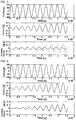
- the inventor of this invention changed the sampling frequency f s of the A/D convertors 16, 17 of the oscillation-velocity detecting device 4 to twice, five times, 10 times and 20 times as much as the drive frequency of the ultrasonic transducer 3 and then verified the oscillating velocity gotten by simulation.
- the values are shown in Figs. 3 to 6 .
- Fig. 3 shows the result of simulation should the sampling frequency f s be twice as much as the drive frequency f o .
- Fig. 4 shows the result of simulation should the sampling frequency f s be five times as much as the drive frequency f o .
- Fig. 5 shows the result of simulation should the sampling frequency f s be 10 times as much as the drive frequency f o .
- Fig. 3 shows the result of simulation should the sampling frequency f s be twice as much as the drive frequency f o .
- Fig. 4 shows the result of simulation should the sampling frequency f s be five times as much as the drive frequency f
- FIG. 6 shows the result of simulation should the sampling frequency f s be 20 times as much as the drive frequency f o .
- the theoretical values of the oscillating velocity are shown as a dotted line, which values are to be computed based on the waveform of the voltage as shown at the top of Figs. 3 to 6 and based on the current as shown in the middle of Figs. 3 to 6 .
- the result of simulation of the oscillating velocity matching each sampling frequency f s is shown as a solid line at the bottom of Figs. 3 to 6 . Also, as shown in Figs.
- the second embodiment of this invention is described in reference to Fig. 7 .
- the ultrasonic transducer 3 is driven at about the resonance frequency (A-type resonance frequency).
- the second embodiment of this invention differs from the first embodiment in that the ultrasonic transducer 3 is driven at about the anti-resonance frequency (B-type resonance frequency).
- the shape of the digital-signal processing part 18 and the value of the force coefficient A B are different from that of the first embodiment of this invention.
- the differences of the first and second embodiments are mainly described.
- the detected value yo(t) of the oscillating velocity within the continuous-time domain is expressed as the following formula (2).
- y 0 t 1 A B ⁇ x 1 t ⁇ ⁇ C d ⁇ x 2 t dt
- the digital-signal processing part 18 of the embodiment of this invention discretizes and approximates the detected value y 0 (t) as shown in the above formula and then, based on the backward-differentiate method, computes the oscillating velocity and emits such velocity as the digital signal y 0 (n).
- the digital-signal processing part 18 of the embodiment of this invention comprises a coefficient multiplier 41, a first-coefficient variable multiplier 42, a delay element 43, an adder 44, a subtractor 45 and a second-coefficient variable multiplier 46.
- the digital-signal processing part 18 computes the oscillating velocity yo(n) of the emitting surface 7 of the ultrasonic transducer 3 by using the digital signals x 1 (n), x 2 (n) that matches the voltage e o (t) and the current i o (t) at the electric terminals 25a, 25b of the ultrasonic transducer 3, together with the digital signal of the braking capacity C d and the force coefficient A B .
- the force coefficient A B of the embodiment of this invention is the ratio between the current running through the electric terminal 25a, 25b and the driving force generated on the emitting surface 7 (mechanical terminal) of the ultrasonic transducer 3 when mechanically vibrating at the anti-resonance frequency (B-type resonance frequency), thus being called a B-type force coefficient.
- the digital signal x 1 (n) of the voltage e o (t) detected by the voltage detector 11 enters the coefficient multiplier 41 that then multiplies the digital signal x 1 (n) by the coefficient ⁇ . Then, such multiplication value enters the subtractor 45.
- the digital signal x 2 (n) of the current i o (t) detected by the current detector 12 enters the first-coefficient variable multiplier 42 while the digital signal of the braking capacity C d enters the first-coefficient variable multiplier 42 by the external input terminal 27a.
- the first-coefficient variable multiplier 42 then multiplies the digital signal x 2 (n) of the current i o (t) by the coefficient ⁇ *T s /C d matching the digital signal of the braking capacity C d . Then, such multiplication value enters the adder 44 but not before it is delayed by the delay element 43. The adder 44 then adds the multiplication value of the coefficient variable multiplier 42 to the delayed signal. Then, the addition value enters the subtractor 45.
- the delay element 43 and the adder 44 work as an integrator in integrating the multiplication value and the first-coefficient variable multiplier 42.
- the subtractor 45 subtracts the addition value of the adder 44 from the multiplication value (the digital signal of the voltage e o (t)) of the coefficient multiplier 41. Then, the subtraction value enters the second-coefficient variable multiplier 46.
- the digital signal of the force coefficient A B enters the second-coefficient variable multiplier 46 by the external input terminal 27b.
- the second-coefficient variable multiplier 46 then multiplies the coefficient 1/A B matching the digital signal of the force coefficient A B by the subtraction value of the subtractor 45 and then emits such multiplication value as the digital signal yo(n) of the oscillating velocity.
- the digital-signal processing part 18 of the embodiment of this invention enters the digital signal of the force coefficient A B (B-type force coefficient) in the motion of the anti-resonance frequency (B-type resonance frequency) and then does digital-signal processing in matching the motion when driving the ultrasonic transducer 3 at about the anti-resonance frequency, thus making it possible in getting more accurately the oscillating velocity of the emitting surface 7 at about the anti-resonance frequency.
- a B B-type force coefficient
Landscapes
- Engineering & Computer Science (AREA)
- Mechanical Engineering (AREA)
- Apparatuses For Generation Of Mechanical Vibrations (AREA)
- Measurement Of Mechanical Vibrations Or Ultrasonic Waves (AREA)
- Transducers For Ultrasonic Waves (AREA)
Claims (3)
- Erkennungsvorrichtung (4) für Oszillationsgeschwindigkeit, die zwischen einem Ultraschallwandler (3), der eine Emissionsoberfläche (7) zum Emittieren von Ultraschallwellen durch Vibration in einem spezifischen Oszillationsmodus aufweist, und einem Ultraschalloszillator (2) zum Antreiben des Ultraschallwandlers (3) durch mechanisches Vibrieren des Ultraschallwandlers (3) bei etwa der Resonanzfrequenz in dem Oszillationsmodus bereitgestellt wird, welche alle innerhalb eines Ultraschallgenerators (1) bereitzustellen sind, um spezifische Verfahren beim Emittieren von Ultraschallwellen von einer Emissionsoberfläche (7) durchzuführen, wobei die Erkennungsvorrichtung (4) für Oszillationsgeschwindigkeit umfasst: ein Eingabemittel zum Eingeben digitaler Signale, die sowohl die Bremskapazität des Ultraschallwandlers (3) als auch den Kraftkoeffizienten der Emissionsoberfläche (7) während der Oszillation in dem spezifischen Oszillationsmodus in Bewegung mit der Resonanzfrequenz zeigen; ein Erkennungsmittel, das mit einem elektrischen Anschluss des Ultraschallwandlers (3) zu verbinden ist, um die analogen Signale der Spannung und des Stroms an dem elektrischen Anschluss zu erkennen; ein Umwandlungsmittel zum Ändern des analogen Signals der Spannung und des Stroms, die von dem Erkennungsmittel erkannt wurden, in digitale Signale; und ein Digitalsignalverarbeitungsmittel zum Durchführen von arithmetischen Operationen auf der Grundlage der Grundformel der elektroakustischen Umwandlung unter Verwendung der digitalen Signale der Bremskapazität, des Kraftkoeffizienten und der Spannung und des Stroms und zum anschließenden Berechnen der Oszillationsgeschwindigkeit der Emissionsoberfläche des Ultraschallwandlers (3), dadurch gekennzeichnet, dass das Digitalsignalverarbeitungsmittel umfasst: ein Verzögerungselement (31, 43) und einen ersten Subtrahierer (32) zum Durchführen einer differentiellen Verarbeitung der digitalen Signale bezüglich der Spannung; einen variablen Multiplizierer (33, 42) der Erstkoeffizienten zum Multiplizieren des Koeffizienten, der dem digitalen Signal der Bremskapazität entspricht, basierend auf dem Subtraktionswert des ersten Subtrahierers (32); einen zweiten Subtrahierer (35) zum Subtrahieren des Multiplikationswerts des variablen Multiplizierers (33, 42) der Erstkoeffizienten von dem digitalen Signal des Stroms; und einen variablen Multiplizierer (36, 46) der Zweitkoeffizienten zum Multiplizieren des Koeffizienten, der mit dem digitalen Signal des Kraftkoeffizienten übereinstimmt, mit dem Subtraktionswert des zweiten Subtrahierers (35) und zum anschließenden Emittieren eines derartigen Multiplikationswerts als die Oszillationsgeschwindigkeit.
- Erkennungsvorrichtung (4) für Oszillationsgeschwindigkeit, die zwischen einem Ultraschallwandler (3), der eine Emissionsoberfläche (7) zum Emittieren von Ultraschallwellen durch Vibration in einem spezifischen Oszillationsmodus aufweist, und einem Ultraschalloszillator (2) zum Antreiben des Ultraschallwandlers (3) durch mechanisches Vibrieren des Ultraschallwandlers (3) bei etwa der Anti-Resonanzfrequenz in dem Oszillationsmodus bereitgestellt wird, welche alle innerhalb eines Ultraschallgenerators (1) bereitzustellen sind, um spezifische Verfahren beim Emittieren von Ultraschallwellen von einer Emissionsoberfläche (7) durchzuführen, wobei die Erkennungsvorrichtung (4) für Oszillationsgeschwindigkeit umfasst: ein Eingabemittel zum Eingeben digitaler Signale, die sowohl die Bremskapazität des Ultraschallwandlers (3) als auch den Kraftkoeffizienten der Emissionsoberfläche (7) während der Oszillation in dem spezifischen Oszillationsmodus in Bewegung mit der Anti-Resonanzfrequenz zeigen; ein Erkennungsmittel, das mit einem elektrischen Anschluss des Ultraschallwandlers (3) zu verbinden ist, um die analogen Signale der Spannung und des Stroms an dem elektrischen Anschluss zu erkennen; ein Umwandlungsmittel zum Ändern des analogen Signals der Spannung und des Stroms, die von dem Erkennungsmittel erkannt wurden, in digitale Signale; und ein Digitalsignalverarbeitungsmittel zum Durchführen von arithmetischen Operationen auf der Grundlage der Grundformel der elektroakustischen Umwandlung unter Verwendung der digitalen Signale der Bremskapazität, des Kraftkoeffizienten und der Spannung und des Stroms und zum anschließenden Berechnen der Oszillationsgeschwindigkeit der Emissionsoberfläche (7) des Ultraschallwandlers (3), dadurch gekennzeichnet, dass das Digitalsignalverarbeitungsmittel umfasst: einen variablen Multiplizierer (33, 42) der Erstkoeffizienten zum Multiplizieren des Koeffizienten, der mit dem digitalen Signal bezüglich der Bremskapazität übereinstimmt, mit dem digitalen Signal bezüglich des Stroms; ein Verzögerungselement (31, 43) und einen Addierer (44) zum Durchführen einer Differenzverarbeitung des Multiplikationswerts des variablen Multiplizierers (33, 42) der Erstkoeffizienten; einen Subtrahierer zum Subtrahieren des Additionswertes des Addierers (44) von dem digitalen Signal bezüglich der Spannung; und einen variablen Multiplizierer (36, 46) der Zweitkoeffizienten zum Multiplizieren der Koeffizienten, der mit dem digitalen Signal des Kraftkoeffizienten übereinstimmt, mit dem Subtraktionswert des Subtrahierers und zum anschließenden Emittieren eines derartigen Multiplikationswertes als die Oszillationsgeschwindigkeit.
- Erkennungsvorrichtung (4) für Oszillationsgeschwindigkeit nach Anspruch 1 oder 2, dadurch gekennzeichnet, dass die Abtastfrequenz des Umwandlungsmittels auf das Doppelte oder mehr als die Antriebsfrequenz des Ultraschallwandlers (3) eingestellt ist.
Applications Claiming Priority (1)
| Application Number | Priority Date | Filing Date | Title |
|---|---|---|---|
| JP2016094418A JP6721233B2 (ja) | 2016-05-10 | 2016-05-10 | 振動速度検出装置 |
Publications (2)
| Publication Number | Publication Date |
|---|---|
| EP3243572A1 EP3243572A1 (de) | 2017-11-15 |
| EP3243572B1 true EP3243572B1 (de) | 2021-05-26 |
Family
ID=58401386
Family Applications (1)
| Application Number | Title | Priority Date | Filing Date |
|---|---|---|---|
| EP17161532.1A Active EP3243572B1 (de) | 2016-05-10 | 2017-03-17 | Erkennungsvorrichtung für oszillationsgeschwindigkeit |
Country Status (2)
| Country | Link |
|---|---|
| EP (1) | EP3243572B1 (de) |
| JP (1) | JP6721233B2 (de) |
Families Citing this family (1)
| Publication number | Priority date | Publication date | Assignee | Title |
|---|---|---|---|---|
| CN120421272B (zh) * | 2025-07-03 | 2025-09-16 | 浙江德硕科技股份有限公司 | 一种超声波清洗产线的全自动数控调节方法及系统 |
Family Cites Families (7)
| Publication number | Priority date | Publication date | Assignee | Title |
|---|---|---|---|---|
| JP2647714B2 (ja) * | 1989-04-28 | 1997-08-27 | オリンパス光学工業株式会社 | 超音波変換器駆動装置 |
| US5151085A (en) * | 1989-04-28 | 1992-09-29 | Olympus Optical Co., Ltd. | Apparatus for generating ultrasonic oscillation |
| JPH081091A (ja) | 1994-06-20 | 1996-01-09 | Suzuki Motor Corp | 超音波振動子の駆動装置 |
| EP1060798A1 (de) * | 1999-06-18 | 2000-12-20 | Prokic Miodrag | Einkolben Ultraschallrichtwandler |
| JP2009166028A (ja) | 2007-12-21 | 2009-07-30 | Shimada Phys & Chem Ind Co Ltd | 超音波処理装置 |
| JP5000671B2 (ja) * | 2009-01-30 | 2012-08-15 | 株式会社カイジョー | 超音波発振器及び超音波洗浄装置 |
| JP2016202190A (ja) * | 2013-09-02 | 2016-12-08 | 株式会社日立製作所 | 超音波診断装置 |
-
2016
- 2016-05-10 JP JP2016094418A patent/JP6721233B2/ja active Active
-
2017
- 2017-03-17 EP EP17161532.1A patent/EP3243572B1/de active Active
Also Published As
| Publication number | Publication date |
|---|---|
| JP2017204689A (ja) | 2017-11-16 |
| JP6721233B2 (ja) | 2020-07-08 |
| EP3243572A1 (de) | 2017-11-15 |
Similar Documents
| Publication | Publication Date | Title |
|---|---|---|
| EP3130903B1 (de) | Eingabe-/ausgabevorrichtung und lenkmessvorrichtung | |
| RU2646541C2 (ru) | Способ формирования сигнала возбуждения для датчика вибрации | |
| GB2236591A (en) | Vibrating element apparatus for fluid density and/or viscosity determination | |
| EP3234546B1 (de) | Steuerung einer schwingung eines schwingungssensors auf der basis eines phasenfehlers | |
| CN104122409A (zh) | 物理量检测电路、物理量检测装置、电子设备以及移动体 | |
| JP7024466B2 (ja) | コリオリ流量計、時期予測システム、及び時期予測方法 | |
| JP2007508544A (ja) | 深さ測定システム | |
| EP3234525B1 (de) | Bestimmung eines schwingungsreaktionsparameters eines vibrationselements | |
| KR101440203B1 (ko) | 점탄성 측정방법 및 점탄성 측정장치 | |
| EP3243572A1 (de) | Oszillierende geschwindigkeitserkennungsvorrichtung | |
| JP5348408B2 (ja) | 物理量検出装置、物理量検出装置の異常診断システム及び物理量検出装置の異常診断方法 | |
| US8893544B2 (en) | Viscosity measuring device and viscosity measuring method | |
| US9927460B2 (en) | Calibrating rotational accelerometers | |
| CN103649691A (zh) | 用于按照超声波传播时间方法确定流体的流量的方法 | |
| JP5831904B2 (ja) | 粘弾性測定方法及び粘弾性測定装置 | |
| JP3998589B2 (ja) | 音圧測定装置及び圧測定方法 | |
| JPH11287681A (ja) | 超音波流量計 | |
| JP5589171B2 (ja) | 物理量検出装置用回路 | |
| RU2190834C2 (ru) | Ультразвуковой одноканальный фазовый бескоммутационный способ измерения расхода | |
| JP6544687B2 (ja) | 液滴検出装置及び液滴検出方法 | |
| Maruyama et al. | Resonance frequency tracing system for langevin type ultrasonic transducers | |
| JP2005098866A (ja) | 振動子を使用した測定方法及びバイオセンサー装置 | |
| JPH03148040A (ja) | 粘度測定装置 | |
| Terakawa et al. | 2P3-6 Three-layer type digital microfluidic system using surface acoustic wave device | |
| Teplykh et al. | Numerical Model of Lateral Electric Field Excited Resonator on Piezoelectric Plate Bordered with Viscous and Conductive Liquid |
Legal Events
| Date | Code | Title | Description |
|---|---|---|---|
| PUAI | Public reference made under article 153(3) epc to a published international application that has entered the european phase |
Free format text: ORIGINAL CODE: 0009012 |
|
| STAA | Information on the status of an ep patent application or granted ep patent |
Free format text: STATUS: REQUEST FOR EXAMINATION WAS MADE |
|
| 17P | Request for examination filed |
Effective date: 20170317 |
|
| AK | Designated contracting states |
Kind code of ref document: A1 Designated state(s): AL AT BE BG CH CY CZ DE DK EE ES FI FR GB GR HR HU IE IS IT LI LT LU LV MC MK MT NL NO PL PT RO RS SE SI SK SM TR |
|
| AX | Request for extension of the european patent |
Extension state: BA ME |
|
| GRAP | Despatch of communication of intention to grant a patent |
Free format text: ORIGINAL CODE: EPIDOSNIGR1 |
|
| STAA | Information on the status of an ep patent application or granted ep patent |
Free format text: STATUS: GRANT OF PATENT IS INTENDED |
|
| INTG | Intention to grant announced |
Effective date: 20210301 |
|
| RIN1 | Information on inventor provided before grant (corrected) |
Inventor name: SHIBUYA, NOBUNAGA |
|
| GRAS | Grant fee paid |
Free format text: ORIGINAL CODE: EPIDOSNIGR3 |
|
| GRAA | (expected) grant |
Free format text: ORIGINAL CODE: 0009210 |
|
| STAA | Information on the status of an ep patent application or granted ep patent |
Free format text: STATUS: THE PATENT HAS BEEN GRANTED |
|
| AK | Designated contracting states |
Kind code of ref document: B1 Designated state(s): AL AT BE BG CH CY CZ DE DK EE ES FI FR GB GR HR HU IE IS IT LI LT LU LV MC MK MT NL NO PL PT RO RS SE SI SK SM TR |
|
| REG | Reference to a national code |
Ref country code: GB Ref legal event code: FG4D |
|
| REG | Reference to a national code |
Ref country code: CH Ref legal event code: EP |
|
| REG | Reference to a national code |
Ref country code: DE Ref legal event code: R096 Ref document number: 602017039109 Country of ref document: DE |
|
| REG | Reference to a national code |
Ref country code: AT Ref legal event code: REF Ref document number: 1395694 Country of ref document: AT Kind code of ref document: T Effective date: 20210615 |
|
| REG | Reference to a national code |
Ref country code: IE Ref legal event code: FG4D |
|
| REG | Reference to a national code |
Ref country code: LT Ref legal event code: MG9D |
|
| REG | Reference to a national code |
Ref country code: AT Ref legal event code: MK05 Ref document number: 1395694 Country of ref document: AT Kind code of ref document: T Effective date: 20210526 |
|
| PG25 | Lapsed in a contracting state [announced via postgrant information from national office to epo] |
Ref country code: HR Free format text: LAPSE BECAUSE OF FAILURE TO SUBMIT A TRANSLATION OF THE DESCRIPTION OR TO PAY THE FEE WITHIN THE PRESCRIBED TIME-LIMIT Effective date: 20210526 Ref country code: BG Free format text: LAPSE BECAUSE OF FAILURE TO SUBMIT A TRANSLATION OF THE DESCRIPTION OR TO PAY THE FEE WITHIN THE PRESCRIBED TIME-LIMIT Effective date: 20210826 Ref country code: AT Free format text: LAPSE BECAUSE OF FAILURE TO SUBMIT A TRANSLATION OF THE DESCRIPTION OR TO PAY THE FEE WITHIN THE PRESCRIBED TIME-LIMIT Effective date: 20210526 Ref country code: FI Free format text: LAPSE BECAUSE OF FAILURE TO SUBMIT A TRANSLATION OF THE DESCRIPTION OR TO PAY THE FEE WITHIN THE PRESCRIBED TIME-LIMIT Effective date: 20210526 Ref country code: LT Free format text: LAPSE BECAUSE OF FAILURE TO SUBMIT A TRANSLATION OF THE DESCRIPTION OR TO PAY THE FEE WITHIN THE PRESCRIBED TIME-LIMIT Effective date: 20210526 |
|
| REG | Reference to a national code |
Ref country code: NL Ref legal event code: MP Effective date: 20210526 |
|
| PG25 | Lapsed in a contracting state [announced via postgrant information from national office to epo] |
Ref country code: PT Free format text: LAPSE BECAUSE OF FAILURE TO SUBMIT A TRANSLATION OF THE DESCRIPTION OR TO PAY THE FEE WITHIN THE PRESCRIBED TIME-LIMIT Effective date: 20210927 Ref country code: PL Free format text: LAPSE BECAUSE OF FAILURE TO SUBMIT A TRANSLATION OF THE DESCRIPTION OR TO PAY THE FEE WITHIN THE PRESCRIBED TIME-LIMIT Effective date: 20210526 Ref country code: NO Free format text: LAPSE BECAUSE OF FAILURE TO SUBMIT A TRANSLATION OF THE DESCRIPTION OR TO PAY THE FEE WITHIN THE PRESCRIBED TIME-LIMIT Effective date: 20210826 Ref country code: SE Free format text: LAPSE BECAUSE OF FAILURE TO SUBMIT A TRANSLATION OF THE DESCRIPTION OR TO PAY THE FEE WITHIN THE PRESCRIBED TIME-LIMIT Effective date: 20210526 Ref country code: RS Free format text: LAPSE BECAUSE OF FAILURE TO SUBMIT A TRANSLATION OF THE DESCRIPTION OR TO PAY THE FEE WITHIN THE PRESCRIBED TIME-LIMIT Effective date: 20210526 Ref country code: GR Free format text: LAPSE BECAUSE OF FAILURE TO SUBMIT A TRANSLATION OF THE DESCRIPTION OR TO PAY THE FEE WITHIN THE PRESCRIBED TIME-LIMIT Effective date: 20210827 Ref country code: LV Free format text: LAPSE BECAUSE OF FAILURE TO SUBMIT A TRANSLATION OF THE DESCRIPTION OR TO PAY THE FEE WITHIN THE PRESCRIBED TIME-LIMIT Effective date: 20210526 Ref country code: IS Free format text: LAPSE BECAUSE OF FAILURE TO SUBMIT A TRANSLATION OF THE DESCRIPTION OR TO PAY THE FEE WITHIN THE PRESCRIBED TIME-LIMIT Effective date: 20210926 |
|
| PG25 | Lapsed in a contracting state [announced via postgrant information from national office to epo] |
Ref country code: NL Free format text: LAPSE BECAUSE OF FAILURE TO SUBMIT A TRANSLATION OF THE DESCRIPTION OR TO PAY THE FEE WITHIN THE PRESCRIBED TIME-LIMIT Effective date: 20210526 |
|
| PG25 | Lapsed in a contracting state [announced via postgrant information from national office to epo] |
Ref country code: SK Free format text: LAPSE BECAUSE OF FAILURE TO SUBMIT A TRANSLATION OF THE DESCRIPTION OR TO PAY THE FEE WITHIN THE PRESCRIBED TIME-LIMIT Effective date: 20210526 Ref country code: SM Free format text: LAPSE BECAUSE OF FAILURE TO SUBMIT A TRANSLATION OF THE DESCRIPTION OR TO PAY THE FEE WITHIN THE PRESCRIBED TIME-LIMIT Effective date: 20210526 Ref country code: DK Free format text: LAPSE BECAUSE OF FAILURE TO SUBMIT A TRANSLATION OF THE DESCRIPTION OR TO PAY THE FEE WITHIN THE PRESCRIBED TIME-LIMIT Effective date: 20210526 Ref country code: EE Free format text: LAPSE BECAUSE OF FAILURE TO SUBMIT A TRANSLATION OF THE DESCRIPTION OR TO PAY THE FEE WITHIN THE PRESCRIBED TIME-LIMIT Effective date: 20210526 Ref country code: CZ Free format text: LAPSE BECAUSE OF FAILURE TO SUBMIT A TRANSLATION OF THE DESCRIPTION OR TO PAY THE FEE WITHIN THE PRESCRIBED TIME-LIMIT Effective date: 20210526 Ref country code: RO Free format text: LAPSE BECAUSE OF FAILURE TO SUBMIT A TRANSLATION OF THE DESCRIPTION OR TO PAY THE FEE WITHIN THE PRESCRIBED TIME-LIMIT Effective date: 20210526 Ref country code: ES Free format text: LAPSE BECAUSE OF FAILURE TO SUBMIT A TRANSLATION OF THE DESCRIPTION OR TO PAY THE FEE WITHIN THE PRESCRIBED TIME-LIMIT Effective date: 20210526 |
|
| REG | Reference to a national code |
Ref country code: DE Ref legal event code: R097 Ref document number: 602017039109 Country of ref document: DE |
|
| PLBE | No opposition filed within time limit |
Free format text: ORIGINAL CODE: 0009261 |
|
| STAA | Information on the status of an ep patent application or granted ep patent |
Free format text: STATUS: NO OPPOSITION FILED WITHIN TIME LIMIT |
|
| 26N | No opposition filed |
Effective date: 20220301 |
|
| PG25 | Lapsed in a contracting state [announced via postgrant information from national office to epo] |
Ref country code: IS Free format text: LAPSE BECAUSE OF FAILURE TO SUBMIT A TRANSLATION OF THE DESCRIPTION OR TO PAY THE FEE WITHIN THE PRESCRIBED TIME-LIMIT Effective date: 20210926 Ref country code: AL Free format text: LAPSE BECAUSE OF FAILURE TO SUBMIT A TRANSLATION OF THE DESCRIPTION OR TO PAY THE FEE WITHIN THE PRESCRIBED TIME-LIMIT Effective date: 20210526 |
|
| PG25 | Lapsed in a contracting state [announced via postgrant information from national office to epo] |
Ref country code: IT Free format text: LAPSE BECAUSE OF FAILURE TO SUBMIT A TRANSLATION OF THE DESCRIPTION OR TO PAY THE FEE WITHIN THE PRESCRIBED TIME-LIMIT Effective date: 20210526 |
|
| REG | Reference to a national code |
Ref country code: DE Ref legal event code: R119 Ref document number: 602017039109 Country of ref document: DE |
|
| PG25 | Lapsed in a contracting state [announced via postgrant information from national office to epo] |
Ref country code: MC Free format text: LAPSE BECAUSE OF FAILURE TO SUBMIT A TRANSLATION OF THE DESCRIPTION OR TO PAY THE FEE WITHIN THE PRESCRIBED TIME-LIMIT Effective date: 20210526 |
|
| REG | Reference to a national code |
Ref country code: CH Ref legal event code: PL |
|
| GBPC | Gb: european patent ceased through non-payment of renewal fee |
Effective date: 20220317 |
|
| REG | Reference to a national code |
Ref country code: BE Ref legal event code: MM Effective date: 20220331 |
|
| PG25 | Lapsed in a contracting state [announced via postgrant information from national office to epo] |
Ref country code: LU Free format text: LAPSE BECAUSE OF NON-PAYMENT OF DUE FEES Effective date: 20220317 Ref country code: LI Free format text: LAPSE BECAUSE OF NON-PAYMENT OF DUE FEES Effective date: 20220331 Ref country code: IE Free format text: LAPSE BECAUSE OF NON-PAYMENT OF DUE FEES Effective date: 20220317 Ref country code: GB Free format text: LAPSE BECAUSE OF NON-PAYMENT OF DUE FEES Effective date: 20220317 Ref country code: FR Free format text: LAPSE BECAUSE OF NON-PAYMENT OF DUE FEES Effective date: 20220331 Ref country code: DE Free format text: LAPSE BECAUSE OF NON-PAYMENT OF DUE FEES Effective date: 20221001 Ref country code: CH Free format text: LAPSE BECAUSE OF NON-PAYMENT OF DUE FEES Effective date: 20220331 |
|
| PG25 | Lapsed in a contracting state [announced via postgrant information from national office to epo] |
Ref country code: BE Free format text: LAPSE BECAUSE OF NON-PAYMENT OF DUE FEES Effective date: 20220331 |
|
| PG25 | Lapsed in a contracting state [announced via postgrant information from national office to epo] |
Ref country code: HU Free format text: LAPSE BECAUSE OF FAILURE TO SUBMIT A TRANSLATION OF THE DESCRIPTION OR TO PAY THE FEE WITHIN THE PRESCRIBED TIME-LIMIT; INVALID AB INITIO Effective date: 20170317 |
|
| PG25 | Lapsed in a contracting state [announced via postgrant information from national office to epo] |
Ref country code: MK Free format text: LAPSE BECAUSE OF FAILURE TO SUBMIT A TRANSLATION OF THE DESCRIPTION OR TO PAY THE FEE WITHIN THE PRESCRIBED TIME-LIMIT Effective date: 20210526 Ref country code: CY Free format text: LAPSE BECAUSE OF FAILURE TO SUBMIT A TRANSLATION OF THE DESCRIPTION OR TO PAY THE FEE WITHIN THE PRESCRIBED TIME-LIMIT Effective date: 20210526 |
|
| PG25 | Lapsed in a contracting state [announced via postgrant information from national office to epo] |
Ref country code: TR Free format text: LAPSE BECAUSE OF FAILURE TO SUBMIT A TRANSLATION OF THE DESCRIPTION OR TO PAY THE FEE WITHIN THE PRESCRIBED TIME-LIMIT Effective date: 20210526 |
|
| PG25 | Lapsed in a contracting state [announced via postgrant information from national office to epo] |
Ref country code: MT Free format text: LAPSE BECAUSE OF FAILURE TO SUBMIT A TRANSLATION OF THE DESCRIPTION OR TO PAY THE FEE WITHIN THE PRESCRIBED TIME-LIMIT Effective date: 20210526 |