EP3242995B1 - Schalldämpfendes element für schalldämpfende einheiten in motoren - Google Patents
Schalldämpfendes element für schalldämpfende einheiten in motoren Download PDFInfo
- Publication number
- EP3242995B1 EP3242995B1 EP16735252.5A EP16735252A EP3242995B1 EP 3242995 B1 EP3242995 B1 EP 3242995B1 EP 16735252 A EP16735252 A EP 16735252A EP 3242995 B1 EP3242995 B1 EP 3242995B1
- Authority
- EP
- European Patent Office
- Prior art keywords
- core
- porous material
- noise attenuating
- attenuating member
- strip
- Prior art date
- Legal status (The legal status is an assumption and is not a legal conclusion. Google has not performed a legal analysis and makes no representation as to the accuracy of the status listed.)
- Active
Links
Images





Classifications
-
- F—MECHANICAL ENGINEERING; LIGHTING; HEATING; WEAPONS; BLASTING
- F02—COMBUSTION ENGINES; HOT-GAS OR COMBUSTION-PRODUCT ENGINE PLANTS
- F02M—SUPPLYING COMBUSTION ENGINES IN GENERAL WITH COMBUSTIBLE MIXTURES OR CONSTITUENTS THEREOF
- F02M35/00—Combustion-air cleaners, air intakes, intake silencers, or induction systems specially adapted for, or arranged on, internal-combustion engines
- F02M35/12—Intake silencers ; Sound modulation, transmission or amplification
- F02M35/1272—Intake silencers ; Sound modulation, transmission or amplification using absorbing, damping, insulating or reflecting materials, e.g. porous foams, fibres, rubbers, fabrics, coatings or membranes
-
- F—MECHANICAL ENGINEERING; LIGHTING; HEATING; WEAPONS; BLASTING
- F01—MACHINES OR ENGINES IN GENERAL; ENGINE PLANTS IN GENERAL; STEAM ENGINES
- F01N—GAS-FLOW SILENCERS OR EXHAUST APPARATUS FOR MACHINES OR ENGINES IN GENERAL; GAS-FLOW SILENCERS OR EXHAUST APPARATUS FOR INTERNAL-COMBUSTION ENGINES
- F01N1/00—Silencing apparatus characterised by method of silencing
- F01N1/08—Silencing apparatus characterised by method of silencing by reducing exhaust energy by throttling or whirling
- F01N1/082—Silencing apparatus characterised by method of silencing by reducing exhaust energy by throttling or whirling by passing the exhaust gases through porous members
-
- F—MECHANICAL ENGINEERING; LIGHTING; HEATING; WEAPONS; BLASTING
- F01—MACHINES OR ENGINES IN GENERAL; ENGINE PLANTS IN GENERAL; STEAM ENGINES
- F01N—GAS-FLOW SILENCERS OR EXHAUST APPARATUS FOR MACHINES OR ENGINES IN GENERAL; GAS-FLOW SILENCERS OR EXHAUST APPARATUS FOR INTERNAL-COMBUSTION ENGINES
- F01N1/00—Silencing apparatus characterised by method of silencing
- F01N1/08—Silencing apparatus characterised by method of silencing by reducing exhaust energy by throttling or whirling
- F01N1/085—Silencing apparatus characterised by method of silencing by reducing exhaust energy by throttling or whirling throttling exhaust gas flow using a central core in a flow passage
-
- F—MECHANICAL ENGINEERING; LIGHTING; HEATING; WEAPONS; BLASTING
- F01—MACHINES OR ENGINES IN GENERAL; ENGINE PLANTS IN GENERAL; STEAM ENGINES
- F01N—GAS-FLOW SILENCERS OR EXHAUST APPARATUS FOR MACHINES OR ENGINES IN GENERAL; GAS-FLOW SILENCERS OR EXHAUST APPARATUS FOR INTERNAL-COMBUSTION ENGINES
- F01N1/00—Silencing apparatus characterised by method of silencing
- F01N1/08—Silencing apparatus characterised by method of silencing by reducing exhaust energy by throttling or whirling
- F01N1/10—Silencing apparatus characterised by method of silencing by reducing exhaust energy by throttling or whirling in combination with sound-absorbing materials
-
- F—MECHANICAL ENGINEERING; LIGHTING; HEATING; WEAPONS; BLASTING
- F01—MACHINES OR ENGINES IN GENERAL; ENGINE PLANTS IN GENERAL; STEAM ENGINES
- F01N—GAS-FLOW SILENCERS OR EXHAUST APPARATUS FOR MACHINES OR ENGINES IN GENERAL; GAS-FLOW SILENCERS OR EXHAUST APPARATUS FOR INTERNAL-COMBUSTION ENGINES
- F01N13/00—Exhaust or silencing apparatus characterised by constructional features
- F01N13/007—Apparatus used as intake or exhaust silencer
-
- F—MECHANICAL ENGINEERING; LIGHTING; HEATING; WEAPONS; BLASTING
- F01—MACHINES OR ENGINES IN GENERAL; ENGINE PLANTS IN GENERAL; STEAM ENGINES
- F01N—GAS-FLOW SILENCERS OR EXHAUST APPARATUS FOR MACHINES OR ENGINES IN GENERAL; GAS-FLOW SILENCERS OR EXHAUST APPARATUS FOR INTERNAL-COMBUSTION ENGINES
- F01N3/00—Exhaust or silencing apparatus having means for purifying, rendering innocuous, or otherwise treating exhaust
- F01N3/08—Exhaust or silencing apparatus having means for purifying, rendering innocuous, or otherwise treating exhaust for rendering innocuous
- F01N3/10—Exhaust or silencing apparatus having means for purifying, rendering innocuous, or otherwise treating exhaust for rendering innocuous by thermal or catalytic conversion of noxious components of exhaust
- F01N3/18—Exhaust or silencing apparatus having means for purifying, rendering innocuous, or otherwise treating exhaust for rendering innocuous by thermal or catalytic conversion of noxious components of exhaust characterised by methods of operation; Control
- F01N3/22—Control of additional air supply only, e.g. using by-passes or variable air pump drives
-
- F—MECHANICAL ENGINEERING; LIGHTING; HEATING; WEAPONS; BLASTING
- F02—COMBUSTION ENGINES; HOT-GAS OR COMBUSTION-PRODUCT ENGINE PLANTS
- F02M—SUPPLYING COMBUSTION ENGINES IN GENERAL WITH COMBUSTIBLE MIXTURES OR CONSTITUENTS THEREOF
- F02M35/00—Combustion-air cleaners, air intakes, intake silencers, or induction systems specially adapted for, or arranged on, internal-combustion engines
- F02M35/10—Air intakes; Induction systems
- F02M35/10209—Fluid connections to the air intake system; their arrangement of pipes, valves or the like
- F02M35/10229—Fluid connections to the air intake system; their arrangement of pipes, valves or the like the intake system acting as a vacuum or overpressure source for auxiliary devices, e.g. brake systems; Vacuum chambers
-
- F—MECHANICAL ENGINEERING; LIGHTING; HEATING; WEAPONS; BLASTING
- F02—COMBUSTION ENGINES; HOT-GAS OR COMBUSTION-PRODUCT ENGINE PLANTS
- F02M—SUPPLYING COMBUSTION ENGINES IN GENERAL WITH COMBUSTIBLE MIXTURES OR CONSTITUENTS THEREOF
- F02M35/00—Combustion-air cleaners, air intakes, intake silencers, or induction systems specially adapted for, or arranged on, internal-combustion engines
- F02M35/12—Intake silencers ; Sound modulation, transmission or amplification
- F02M35/1205—Flow throttling or guiding
- F02M35/1211—Flow throttling or guiding by using inserts in the air intake flow path, e.g. baffles, throttles or orifices; Flow guides
-
- F—MECHANICAL ENGINEERING; LIGHTING; HEATING; WEAPONS; BLASTING
- F02—COMBUSTION ENGINES; HOT-GAS OR COMBUSTION-PRODUCT ENGINE PLANTS
- F02M—SUPPLYING COMBUSTION ENGINES IN GENERAL WITH COMBUSTIBLE MIXTURES OR CONSTITUENTS THEREOF
- F02M35/00—Combustion-air cleaners, air intakes, intake silencers, or induction systems specially adapted for, or arranged on, internal-combustion engines
- F02M35/12—Intake silencers ; Sound modulation, transmission or amplification
- F02M35/1277—Reinforcement of walls, e.g. with ribs or laminates; Walls having air gaps or additional sound damping layers
Definitions
- This application relates to noise attenuation in engine systems such as internal combustion engines, more particularly to the inclusion of a noise attenuating member in a housing configured for insertion in a fluid flow path of an engine.
- Engines for example vehicle engines, often include aspirators and/or check valves.
- the aspirators are used to generate a vacuum that is lower than engine manifold vacuum by inducing some of the engine air to travel through a venturi.
- the aspirators may include check valves therein or the system may include separate check valves. When the check valves are separate they are typically included downstream between the source of vacuum and the device using the vacuum.
- fluid means any liquid, suspension, colloid, gas, plasma, or combinations thereof.
- radial means in a direction generally outward from the central portion of an object and does not imply any particular shape, i.e., the shape is not limited to circular, cylindrical, or spherical.
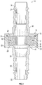
- FIG. 1 is front perspective view of a noise attenuating unit, generally identified by reference number 10, for use in an engine, for example, in a vehicle's engine.
- the engine may be an internal combustion engine, and the vehicle and or engine may include a device requiring a vacuum.
- Check valves and or aspirators are often connected to an internal combustion engine before the engine throttle and after the engine throttle.
- the engine and all its components and/or subsystems are not shown in the figures and it is understood that the engine components and/or subsystems may include any components common to an internal combustion engine.
- the brake boost system is one example of a subsystem that can be connected to an aspirator and/or check valves.
- any one of a fuel vapor purge systems, exhaust gas recirculation system, a crankcase ventilation system and/or a vacuum amplifier may be connected to an aspirator and/or check valve.
- the fluid flow within the aspirator and/or check valves, in particular when a Venturi portion is included, is generally classified as turbulent. This means that in addition to the bulk motion of the fluid flow, such as air or exhaust gases, there are pressure waves traveling through the assembly and different natural frequencies can become excited thereby resulting in turbulence generated noise.
- the noise attenuation unit 10 disclosed herein attenuates such turbulence generated noise.
- the noise attenuation unit 10 may be disposed in, and thereby becomes part of, any fluid flow path(s) within an engine in need of noise attenuation, and is typically positioned in the flow path downstream of the source of the noise.
- the noise attenuating unit 10 includes a housing 14 defining an internal cavity 16 enclosing a noise attenuating member 20 therein.
- the noise attenuating member 20 typically fits securely, at least axially, within the internal cavity 16 sandwiched between a first seat 26 and a second seat 28. As illustrated in FIG. 2 , the noise attenuating member 20 has a generally close fit with the interior side wall 17 of the cavity 16, but such a construction is not required.
- first and second ports 22, 24 both include fitting features 32, 34 for connecting the noise attenuating unit 10 into a fluid flow path of the engine.
- fitting features 32, 34 are insertable into a hose or conduit and the fitting features provide a secure fluid-tight connection thereto.
- the housing 14, as shown in FIG. 2 may be a multiple piece housing with a plurality of pieces connected together with a fluid-tight seal.
- the multiple pieces may include a first housing portion 36 that includes the first port 22 and a male end 23 and a second housing portion 38 that includes the second port 24 and a female end 25.
- the male end 23 is received in the female end 25 with a sealing member 18 therebetween to provide a fluid-tight seal between the portions 36, 38.
- the first housing portion 36 and the second housing portion 38 have a container and cap-type construction.
- the first port 22 and the second port 24 are positioned opposite one another to define a generally linear flow path through the noise attenuation unit 10, but is not limited to this configuration.
- the first and second ports 22, 24 may be positioned relative to one another at an angle of less than 180 degrees.
- the second port 24 may be positioned generally 90 degrees relative to the first port 22 such that the fluid flow passes through the noise attenuating member 20 from an inner cavity of a core of the noise attenuating member 20 radially outward through the porous material disposed about the core of the noise attenuating member 20.
- the noise attenuating member 20 is dimensioned for a tight fit within the housing thereby the fluid flow through the internal cavity 16 is only available through the noise attenuating member 20 itself and any bores it may include.
- the noise attenuating member 20 is porous such that fluid flow through the unit 10 is restricted the least amount possible, but sound (turbulence generated noise) is attenuated. Additional examples of noise attenuating units having noise attenuating members can be found in copending U.S. Patent Application No. 14/565,075, filed December 9, 2014 .
- the noise attenuating member of the present disclosure may also be incorporated directly into a check valve assembly or vacuum producing assembly. Examples of check valve and vacuum producing assemblies that can include a noise attenuating member are included in copending U.S. Patent Application 14/509,612, filed October 8, 2014 .
- the noise attenuating member 20 includes a core 40 and a porous material 42 disposed about the core 40.
- the core 40 is hollow and includes an inner surface 46 defining an inner hollow cavity 48, and an exterior surface 50 facing outward from the core 40.
- the core 40 has a plurality of radial openings 52 to allow for fluid to flow radially outward from the inner cavity 48 of the core 40, through the radial openings 52, and into and through the porous material 42 disposed about the exterior surface 50 of the core 40.
- the porous material 42 includes a plurality of pores (not shown) to allow fluid to pass into and through the porous material 42.
- the noise attenuating member 20 may have a first end 54 and a second end 56, relative to an axial direction of the noise attenuating member 20.
- the fluid flow may be in a direction from the first end 54 to the second end 56 or in a direction from the second end 56 to the first end 54.
- the fluid flow may flow into the inner cavity 48 from either or both of the first end 54 and second end 56 and then flow radially outward through the radial openings 52 and into/through the porous material 42.
- the core 40 may be solid and may have the porous material 42 disposed about the exterior surface 50 of the core 40 such that fluid flow through the noise attenuating member 20 parallel to a center axis 58 of the noise attenuating member 20 is all directed through the porous material.
- the interior surface 46 and the exterior surface 50 of the core 40 have a general cross-sectional shape, relative to the center axis 58 of the noise attenuating member 20, that may be any convenient shape, including, but not limited to, circular, square, rectangular, polygonal, multi-faceted, or other shape.
- the interior surface 46 and the exterior surface 50 may have similar cross-sectional shapes, or the cross-sectional shapes of the surfaces 46, 50 may be different. In one embodiment shown in FIGS.
- the core 40 may be an annular cylinder, for which the cross-sectional shape of both the interior surface 46 and exterior surface 50 are generally circular.
- the cross-sectional shapes (notwithstanding the radial openings 52) of the interior surface 46 and the exterior surface 50 may change along a length L of the core 40.
- a width W and the length L of the core 40 may be selected based on the configuration and dimensions of the housing 14 of the noise attenuation unit 10 into which the noise attenuating member 20 is to be incorporated.
- the core 40 may be constructed of any suitable material, including, but not limited to, metal, plastic, ceramic, carbon fiber, glass, fiberglass, wood, rubber, or combinations thereof, and may have one or more surface coatings to prevent deterioration of the core 40.
- the core 40 is constructed of a rigid material.
- the material of the core 40 is not degraded or deteriorated by operating conditions of the fluid system into which it is installed, specifically the elevated temperatures and vibrations that occur in an engine.
- the core material is selected to withstand elevated temperatures.
- the core material is selected to resist corrosion from moisture and other corrosive compounds.
- the radial openings 52 through the core 40 may be any convenient shape, including, but not limited to, circular, square, rectangular, polygonal, multi-faceted, or other shape.
- the radial openings 52 may all have the same shape and size, or one or more of the radial openings 52 may have a shape and/or size that is different from the other radial openings 52.
- the radial openings 52 may have the same general shape, which is generally rectangular with rounded corners. In other embodiments, the radial openings 52 may be generally circular in cross-section.
- the radial openings 52 may be any convenient size and may be selected to increase exposure of the fluid flow to the porous material 42 as the fluid flows through the inner cavity 48.
- each of the radial openings 52 are larger in size than the pores of the porous material 42 disposed about the core 40, but are not so large that the core 40 is deformed into the inner cavity 48 by a weight or force exerted on the core 40 by the porous material 42.
- each of the radial openings 52 may have an area in a range of about 0.7 to about 1.5 times a cross-sectional area of the inner cavity 48.
- each of the radial openings 52 may be in a range of about 0.9 to about 1.3 times the cross-sectional area of the inner cavity 48.
- each of the radial openings 52 may have an area that is in a range of about 1.0 to about 1.2 times the cross-sectional area of the inner cavity 48.
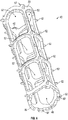
- the radial openings 52 may be distributed along the entire length L of the core, from the first end 54 to the second end 56 of the noise attenuating member 20, and may be distributed angularly along an outer cross-sectional circumference 60 of the core 40. In the embodiment of FIGS. 6 and 7 , the radial openings 52 are distributed evenly throughout the core 40 in both the axial and angular directions. In one embodiment, the radial openings 52 may not be evenly spaced but may be positioned to manipulate the flow dynamics through the noise attenuating member 20. In the embodiment illustrated in FIG. 6 , the core 40 has a total of 12 radial openings 52 arranged in three sections of four radial openings 52 that are distributed evenly about the outer circumference of the core 40.
- the three sections are axial sections with respect to the axial length L of the core 40.
- the four radial openings 52 in each section are aligned radially about the outer circumference of the core 40, and the radial openings 52 are also aligned with the radial openings 52 of an adjacent section.
- the radial openings 52 may be offset or staggered with respect to either or both of radial openings 52 of the same section or different sections.
- the core 40 may have more or less than three sections of radial openings 52 and may have more or less than four radial openings 52 per section.
- a total void space of the exterior surface 50 of the core 40 may be defined as the sum of the cross-sectional areas of the radial openings 52, and a theoretical outer surface area of the core 40 may be defined as the surface area of the exterior surface 50 of the core 40 without the radial openings 52.
- the total void space represented by the radial openings 52 may be in a range of about 50% to about 95% of the theoretical exterior surface area of the core 40.
- the total void space represented by the plurality of radial openings 52 may be in a range of about 60% to about 90% of the theoretical exterior surface area of the core 40.
- the total void space may be in a range of about 70% to about 80% of the theoretical exterior surface area of the core 40.
- the total void space is about 75% of the theoretical exterior surface area of the core 40.
- the core 40 may be a support structure resembling a hollow cylindrical grid/framework.
- the core 40 may be a hollow cylindrical grid made up of wall segments connected or coupled together to define the plurality of radial openings 52.
- the core 40 may be a cylindrical lattice of integrated wall portions defining the plurality of openings 52.
- the core 40 may include a plurality of pieces that are coupled together or engaged to make the core 40.
- the core 40 may have a plurality of protrusions 62 extending radially outward from the exterior surface 50 of the core 40.
- Each of the protrusions 62 may include a feature 64 (or retaining feature), as shown in FIG. 8 , that retains the porous material 42 against the exterior 50 of the core 40.
- the retaining feature 64 include, but are not limited to, barbs, notches, ribs, textured surfaces, other protruding features, or combinations thereof.
- the feature 64 includes one or more barbs that catch on the porous material 42 coupling it to the exterior surface 50 of the core 40.
- the protrusions 62 may be distributed along the entire exterior 50 of the core 40, the distribution being both axial and angular. In one embodiment, the protrusions 62 may be concentrated in a specified region of the exterior surface 50 of the core 40, such as a region where the porous material 42 is first attached prior to being wound around the core 40.
- the core 40 has end surfaces 68 facing generally in opposing axial directions and positioned at the first end 54 and second end 56 of the noise attenuating member 20.
- One or both of the end surfaces 68 of the core 40 may have one or more engagement features 66 for engagement of the core 40 with a machine during one or more assembly operations.
- the engagement features 66 may include one or more shoulders 67 against which a drive surface of a drive mechanism may engage to rotate the core 40 during assembly operations.
- the engagement features 66 may be one or more tabs, pins, or other protrusions that are received in a drive mechanism to engage the drive mechanism with the core 40 for rotation therewith during assembly operations.
- more than one type of engagement feature 66 may be used for engagement with a drive mechanism.
- the porous material 42 disposed about the core 40 may have pores (not shown) with a pore size that is less than the radial openings 52 in the core 40, but large enough to not unduly restrict or interfere with fluid flow such as, for example, air flow through the system.
- the pores may be a network of hollow channels in a porous material 42, such as the channels propagating through a sponge material, or may also be an interconnected matrix of void spaces extending through the porous material 42, such as the void spaces between fibers of a woven fabric or between layers of a wire mesh.
- the porous material 42 can be made from a variety of materials including, but not limited to, metals, plastics, ceramics, glass, or combinations thereof.
- the porous material 42 may be a wire, a wool, a matrix of woven particles, a matrix of matted particles, a matrix of sintered particles, a woven fabric, a matted fabric, a mesh, a sponge, or combinations thereof.
- Porous material 42 made from metals include, but are not limited to, metal wire mesh, metal wire wool, metal wire felt, or combinations thereof.
- the porous material 42 is a wire mesh.
- the porous material 42 may be a woven plastic or nylon fabric.
- the porous character of the sound attenuating member 20 causes the noise pressure waves propagating through the fluid to attenuate by interfering with themselves.
- the porous material 42 is not harmed (does not deteriorate) by operating temperatures of an engine based on placement of the noise attenuating member 20 in the engine system. Additionally, the porous material 42 is not harmed by the vibrations experienced during operating conditions of the engine.
- the porous material 42 may be formed as a plurality of layers of porous material 42 wound around the core 40.
- the porous material 42 may be a continuous strip 70 (strip) of porous material having a first end 72 and a second end 74.
- the first end 72 may be coupled to the exterior 50 of the core 40, and the strip 70 may be wound around the exterior 50 of the core 40 until the porous material 42 reaches a specified thickness, which may depend upon the geometry of the noise attenuating unit 10 into which the noise attenuating member 20 is to be incorporated.
- the first end 72 of the strip 70 may be engaged with the protrusions 62 extending from the exterior 50 of the core 40 such that the protrusions 62 extend through the strip 70 of porous material to hold the strip 70 in engagement with the core 40.
- the first end 72 of the strip 70 may be folded over onto itself so that a portion of the strip 70 that engages with the core 40/protrusions 62 has two layers of porous material, which may act to improve or strengthen the engagement of the strip 70 with the core 40. Tension on the strip 70 during the winding process may change the density of the porous material 42 disposed about the core 40.
- the second end 74 of the strip 70 is then secured to an outermost layer 76 of porous material 42, or other structure, to keep the strip 70 from unwinding from the core 40.
- the second end 74 may be welded, fastened, adhered, taped or otherwise attached to the outermost layer 76 of porous material 42. In one embodiment, the second end 74 is welded to the outermost layer 76 of porous material 42.
- a method of making a noise attenuating member 20 includes providing a core 40 having an interior surface 46 that defines an inner hollow cavity 48 for fluid flow therethrough, providing a strip 70 of porous material 42 having a first end 72 and a second end 74, and wrapping the strip 70 of porous material 42 about the core 40 beginning from the first end 72 to form one or more layers of porous material 42 disposed about the core 40.
- the core 40 is provided having a plurality of radial openings 52 extending therethrough.
- the axial end surfaces 68 of the core 40 can have engagement features 66 to allow for engagement of the core 40 with a machine capable of rotating the core 40 during the assembly operations.
- the method of making a noise attenuating member 20 includes the steps of engaging the core 40 with a machine capable of rotating the core 40 about an axis.
- the center axis 58 is the center of rotation for the core 40.
- the method may include folding over the first end 72 of the strip 70 so that the first end 72 of the strip 70 has two layers of material.
- the method also includes engaging the first end 72 of the porous material 42 with the exterior surface 50 of the core 40.
- the first end 72 of the strip 70 may be engaged with the protrusions 62, and the retaining features 64 thereon, securing the first end 72 of the strip 70 to the exterior surface 50 of the core 40.
- the first end 72 of the strip 70 may be curled over, crimped tight to, or crimp welded to the exterior 50 of the core 40.
- the core 40 may be rotated to wind the strip 70 of porous material 42 about the core 40 to form one or more layers of porous material 42 disposed about the core 40.
- the method may further include applying tension to the strip 70 and adjusting the tension to achieve a specified density of the porous material 42 wound around the core 20.
- the second end 74 of the strip 70 may be secured to an outermost layer 76 of porous material 42, such as through welding, sintering, fastening, or adhering, for example.
- the core 40 may have multiple pieces such that assembling the core 40 happens prior to engaging the first end 72 of the strip 70 with the exterior surface 50.
- the assembled noise attenuating member 20 may be installed in a noise attenuation unit 10, which may be incorporated into a fluid flow system requiring sound attenuation.
- fluid flows into the noise attenuation unit 10 through the first port 22 and through the noise attenuating member 20.
- Some of the fluid flows directly into the porous material 42, where the flow through the plurality of pores disrupts the turbulent flow eddies entering the noise attenuation unit 10.
- the turbulent nature of the flow also causes fluid to flow radially through the radial openings 52 in the core 40 and into the porous material 42, which further dissipates the turbulent eddies that give rise to sound vibrations.
- the fluid flow exits from the porous material 42 and out of the noise attenuation unit 10 through the second port 24.
- the noise attenuating member 20 of the present application may produce repeatable attenuation with minimal interference with fluid flow through the system.
- the core 40 provides a support for the porous material 42 to keep the porous material 42 in place within the noise attenuating unit 10 into which it is installed.
- the hollow internal cavity 48 of the core 40 may provide a straight flow path through the noise attenuating member 20, which may reduce the pressure drop across the noise attenuating member 20 compared to existing noise attenuating devices.
- the core 40 provides support for the porous material 42 to keep the porous material 42 from being drawn into the flow path and interfering with the fluid flow through the noise attenuating unit 10. Providing a means of engagement of the strip 70 of porous material 42 with the core 40 may also reduce the welding that must be performed on a noise attenuating member 20 and thus maintain fluid flow through the noise attenuating member.
Landscapes
- Engineering & Computer Science (AREA)
- Chemical & Material Sciences (AREA)
- Combustion & Propulsion (AREA)
- Mechanical Engineering (AREA)
- General Engineering & Computer Science (AREA)
- Health & Medical Sciences (AREA)
- Chemical Kinetics & Catalysis (AREA)
- Toxicology (AREA)
- Exhaust Silencers (AREA)
- Soundproofing, Sound Blocking, And Sound Damping (AREA)
- Motor Or Generator Frames (AREA)
Claims (14)
- Schalldämpfendes Element (20), mit:einem Kern (40), der hohl ist und eine innere Fläche (46) aufweist, die einen inneren Hohlraum (48) definiert, durch den Fluidstrom gelangen kann und eine äußere Fläche (50) hat, die von dem Kern nach außen weist, sowie axiale Endflächen (68), wobei der Kern (40) als hohlzylindrisches Gitter geformt ist, das mehrere radiale Öffnungen (52) definiert; undeinem porösen Material (42), das um die äußere Fläche (50) des Kerns angeordnet ist;wobei ein Fluidstrom durch den Hohlraum (48) und die radialen Öffnungen (52) durch das poröse Material (42) gelangt;dadurch gekennzeichnet, dass jede der radialen Öffnungen (52) größer ist als eine Porengröße des porösen Materials (42) und eine Fläche in einem Bereich von 0,7 bis 1,5 mal einer Querschnittsfläche des Hohlraums (48) hat und dass ein durch die radialen Öffnungen (52) wiedergegebener, totaler leerer Raum in einem Bereich von 50% bis 95% der theoretischen Außenoberfläche des Kerns (40) ist;wobei eine Endfläche (68) des Kerns (40) einen Eingriffsteil (66) hat zum Eingriff des Kerns mit einer Maschine zum Zwecke des Drehens des Kerns;wobei das poröse Material (42) mehrere Schichten aus porösem Material (42) von einem kontinuierlichen Band (70) ist, das um den Kern (40) gewunden ist, wobei dessen äußerstes Ende (74) an einer äußersten Schicht (66) des porösen Materials (42) angebracht ist.
- Schalldämpfendes Element nach Anspruch 1, wobei das kontinuierliche Band (70) aus porösem Material ein erstes Ende (72) hat, das über sich selbst gefaltet ist, um in Eingriff mit der äußeren Fläche (50) des Kerns zu gelangen.
- Schalldämpfendes Element nach Anspruch 1, wobei der Kern (40) ferner mehrere Vorsprünge (62) umfasst, die sich von der äußeren Fläche (50) des Kerns nach außen erstrecken und jeder Vorsprung ein oder mehrere Teile (64) aufweist, der/die das poröse Material (42) gegen die äußere Fläche (50) des Kerns hält/halten.
- Schalldämpfendes Element nach Anspruch 1, wobei das poröse Material (42) eines oder mehr der Materialien Metall, Kohlefaser, Keramik, Kunststoff und Glas umfasst.
- Schalldämpfendes Element nach Anspruch 4, wobei das poröse Material (42) ein Draht, eine Wolle, eine Matrix aus Gewebepartikeln, eine Matrix aus mattierten Partikeln, eine Matrix aus gesinterten Partikeln, ein Stoff, ein mattiertes Gewebe, ein Geflecht, ein Schwamm oder Kombinationen deren ist.
- Schalldämpfendes Element nach Anspruch 4, wobei das poröse Material (42) Metall umfasst und ein oder mehr der Materialien Metalldraht-Gewebe, Metalldraht-Wolle und Metallmaschen-Filz ist.
- Schalldämpfende Einheit (10) für einen Fluidstromweg, mit:einem Gehäuse (14), das einen inneren Hohlraum (16) definiert und einen ersten Anschluss (22) und einen zweiten Anschluss (24) hat, die jeweils verbindbar sind mit einem Fluidstromweg, um miteinander fluidmäßig über den inneren Hohlraum zu kommunizieren; undeinem dämpfenden Element (20) nach Anspruch 1, das in den inneren Hohlraum (16) des Gehäuses innerhalb den Strom des Fluidflusses zwischen dem ersten Anschluss (22) und dem zweiten Anschluss (24) gesetzt ist und wobei die fluidmäßige Kommunikation zwischen dem ersten Anschluss und dem zweiten Anschluss einen Fluidstrom durch das dämpfende Element beinhaltet.
- Schalldämpfende Einheit nach Anspruch 7, wobei das Gehäuse (14) ein zweiteiliges Gehäuse ist, das einen ersten Gehäuseabschnitt (36) und einen zweiten Gehäuseabschnitt (38) hat.
- Schalldämpfende Einheit nach Anspruch 7, wobei die Fluidstrombahn von dem ersten Anschluss (22) zu dem zweiten Anschluss (24) axial durch das dämpfende Element (20) verläuft.
- Schalldämpfende Einheit nach Anspruch 7, wobei der Fluidstromweg von dem ersten Anschluss (22) zu dem zweiten Anschluss (24) durch das dämpfende Element (20) von dem Hohlraum (48) radial durch das poröse Material (42) nach außen verläuft.
- Schalldämpfende Einheit nach Anspruch 7, wobei das Gehäuse (14) mit einem Venturi-Gerät integriert ist, um Vakuum zu erzeugen.
- Verfahren zur Herstellung eines schalldämpfenden Elements (20), das umfasst:Vorsehen eines Kerns (40), der hohl und als hohlzylindrisches Gitter ausgebildet ist und eine innere Fläche (46) aufweist, die einen inneren Hohlraum (48) aufweist, durch den Fluidstrom gelangen kann und eine äußere Fläche (50) hat, die von dem Kern (40) nach außen weist und mehrere radiale Öffnungen (52) und axiale Endflächen (68) definiert, wobei eine Endfläche (68) einen Eingriffsteil zum Eingriff des Kerns mit einer Maschine zum Zwecke des Drehens des Kerns hat, wobei der Kern (40) mehrere Vorsprünge (62) hat, welche sich von seiner äußeren Fläche (50) nach außen erstrecken und wobei jede der radialen Öffnungen (52) eine Fläche in einem Bereich von 0,7 bis 1,5 mal einer Querschnittsfläche des Hohlraums (48) hat, und ein durch die radialen Öffnungen (52) wiedergegebener, totaler leerer Raum in einem Bereich von 50% bis 95% der theoretischen Außenoberfläche des Kerns ist,Vorsehen eines Bandes aus porösem Material (70), wobei das Band ein erstes Ende (72) und ein zweites Ende (74) hat;in Eingriff bringen des Bandes aus porösem Material (70) mit den Vorsprüngen (62), um das poröse Material gegen den Kern zu halten; undWickeln des Bandes aus porösem Material (70) um den Kern (50), ausgehend von dem ersten Ende (72), um mehrere Schichten aus porösem Material dort herum auszubilden.
- Verfahren nach Anspruch 12, ferner umfassend das Falten des ersten Endes (72) des Bandes aus porösem Material über sich selbst vor dem Wickeln des Bandes aus porösem Material um den Kern (50).
- Verfahren nach Anspruch 12, ferner umfassend das Einstellen eines während des Wickelns dem Band aus porösem Material (70) auferlegten Zuges, um die Dichte der um den Kern (50) gewickelten einen oder mehreren Schichten aus porösem Material zu ändern.
Applications Claiming Priority (2)
| Application Number | Priority Date | Filing Date | Title |
|---|---|---|---|
| US14/593,361 US9382826B1 (en) | 2015-01-09 | 2015-01-09 | Noise attenuating member for noise attenuating units in engines |
| PCT/US2016/012033 WO2016111921A1 (en) | 2015-01-09 | 2016-01-04 | Noise attenuating member for noise attenuating units in engines |
Publications (3)
| Publication Number | Publication Date |
|---|---|
| EP3242995A1 EP3242995A1 (de) | 2017-11-15 |
| EP3242995A4 EP3242995A4 (de) | 2018-07-04 |
| EP3242995B1 true EP3242995B1 (de) | 2020-05-20 |
Family
ID=56234832
Family Applications (1)
| Application Number | Title | Priority Date | Filing Date |
|---|---|---|---|
| EP16735252.5A Active EP3242995B1 (de) | 2015-01-09 | 2016-01-04 | Schalldämpfendes element für schalldämpfende einheiten in motoren |
Country Status (7)
| Country | Link |
|---|---|
| US (1) | US9382826B1 (de) |
| EP (1) | EP3242995B1 (de) |
| JP (1) | JP6731926B2 (de) |
| KR (1) | KR102269213B1 (de) |
| CN (1) | CN105960512B (de) |
| BR (1) | BR112017014721B1 (de) |
| WO (1) | WO2016111921A1 (de) |
Families Citing this family (4)
| Publication number | Priority date | Publication date | Assignee | Title |
|---|---|---|---|---|
| FR3036731B1 (fr) * | 2015-05-29 | 2017-05-19 | Novares France | Dispositif d'attenuation des bruits de bouche et des bruits rayonnes |
| US11217221B2 (en) * | 2019-10-03 | 2022-01-04 | GM Global Technology Operations LLC | Automotive noise mitigation |
| DE102021119960A1 (de) | 2020-08-14 | 2022-02-17 | Mann+Hummel Gmbh | Luftführungsleitung einer Brennkraftmaschine |
| WO2023143204A1 (zh) * | 2022-01-30 | 2023-08-03 | 浙江盾安人工环境股份有限公司 | 阀芯部件及多通阀 |
Family Cites Families (43)
| Publication number | Priority date | Publication date | Assignee | Title |
|---|---|---|---|---|
| US2037884A (en) | 1932-11-11 | 1936-04-21 | Burgess Lab Inc C F | Silencer |
| US2626009A (en) | 1950-04-11 | 1953-01-20 | Houdaille Hershey Corp | Air cleaner, intake silencer, and carburetor housing unit |
| US2954091A (en) | 1956-06-18 | 1960-09-27 | Gen Motors Corp | Cleaner silencer assembly |
| US3430437A (en) | 1966-10-05 | 1969-03-04 | Holley Carburetor Co | Automotive exhaust emission system |
| DE1750021A1 (de) | 1968-03-21 | 1971-01-07 | Fichtel & Sachs Ag | Ventileinrichtung fuer hydraulische,pneumatische oder hydropneumatische Einrichtungen |
| US3826281A (en) | 1969-10-29 | 1974-07-30 | Us Navy | Throttling ball valve |
| US3614859A (en) | 1969-11-17 | 1971-10-26 | Ingersoll Rand Co | Gas filter-silencer |
| US3842932A (en) | 1972-11-01 | 1974-10-22 | S Gibel | Sound-trap muffler |
| US4184565A (en) * | 1978-12-15 | 1980-01-22 | Harris V C | Exhaust muffler |
| IT8104805U1 (it) | 1981-03-31 | 1982-10-01 | Panda Srl | Silenziatore di scarico in particolare per pistole e attrezzature pneumatiche |
| JPS57162916U (de) * | 1981-04-08 | 1982-10-14 | ||
| US4408679A (en) * | 1981-09-28 | 1983-10-11 | Peabody Spunstrand, Inc. | Sound attenuator |
| DE3531353A1 (de) * | 1985-09-03 | 1987-03-12 | Audi Ag | Ladeluftkuehler fuer aufgeladene brennkraftmaschine |
| US4951708A (en) | 1988-11-30 | 1990-08-28 | General Motors Corporation | Vacuum check valve |
| US4938309A (en) | 1989-06-08 | 1990-07-03 | M.D. Manufacturing, Inc. | Built-in vacuum cleaning system with improved acoustic damping design |
| US5291916A (en) | 1992-12-28 | 1994-03-08 | Excel Industries, Inc. | Check valve |
| US5326942A (en) | 1993-02-09 | 1994-07-05 | Schmid Jerry W | Noise suppression muffler for moisture laden exhaust gases & method |
| JP2590168Y2 (ja) * | 1993-08-27 | 1999-02-10 | 有限会社ジースプロジェクト | 内燃機関用消音器 |
| JPH07117010A (ja) | 1993-10-27 | 1995-05-09 | Matsushita Electric Works Ltd | 単板の補修方法 |
| JP2719890B2 (ja) * | 1994-09-16 | 1998-02-25 | 株式会社ユタカ技研 | 消音器 |
| JPH08174860A (ja) | 1994-10-26 | 1996-07-09 | Seiko Epson Corp | インクジェットプリンタ用インクカートリッジ |
| JPH09144986A (ja) * | 1995-11-27 | 1997-06-03 | Nissan Motor Co Ltd | 吸音ダクト構造体 |
| US5801342A (en) * | 1997-01-27 | 1998-09-01 | Lindab Ab | Double-walled structure and method and arrangement for producing the same |
| US6382931B1 (en) | 1998-02-24 | 2002-05-07 | Respironics, Inc. | Compressor muffler |
| SE515765C2 (sv) * | 2000-02-22 | 2001-10-08 | Lindab Ab | Dubbelväggig konstruktion och sätt att tillverka densamma |
| DE10022240A1 (de) | 2000-05-08 | 2001-11-15 | Abb Turbo Systems Ag Baden | Filterschalldämpfer |
| CN100348865C (zh) | 2001-09-06 | 2007-11-14 | 爱发科股份有限公司 | 真空排气装置以及真空排气装置的运转方法 |
| US7131514B2 (en) | 2003-08-25 | 2006-11-07 | Ford Global Technologies, Llc | Noise attenuation device for a vehicle exhaust system |
| CN1279868C (zh) | 2003-08-26 | 2006-10-18 | 苏州金莱克清洁器具有限公司 | 吸尘器消音装置 |
| US20050121084A1 (en) | 2003-12-04 | 2005-06-09 | Danfoss Flomatic Corporation | Ball check valve |
| US7631726B2 (en) * | 2004-06-28 | 2009-12-15 | Mahle International Gmbh | Silencer for air induction system and high flow articulated coupling |
| US20060016477A1 (en) | 2004-07-23 | 2006-01-26 | Algis Zaparackas | Vacuum enhancing check valve |
| US8360199B2 (en) | 2006-05-30 | 2013-01-29 | Mann + Hummel Gmbh | Integrated mass air flow sensor and broadband silencer |
| JP2008231979A (ja) * | 2007-03-19 | 2008-10-02 | Roki Co Ltd | 消音チャンバーダクト |
| JP5064453B2 (ja) * | 2009-07-31 | 2012-10-31 | 本田技研工業株式会社 | 車両用エンジンの排気管に設けられる消音器 |
| JP5395560B2 (ja) * | 2009-08-04 | 2014-01-22 | 株式会社東芝 | 消音器および電気掃除機 |
| US20110186151A1 (en) | 2010-02-04 | 2011-08-04 | Bernard Joseph Sparazynski | Check valve |
| DE102010033091A1 (de) | 2010-08-02 | 2012-02-02 | Schaeffler Technologies Gmbh & Co. Kg | Hydraulisches Spannausgleichselement |
| GB2491094A (en) * | 2011-05-12 | 2012-11-28 | Jaguar Cars | Air induction system comprising noise damper and hydrocarbon trap |
| CN104040455B (zh) | 2011-08-17 | 2016-06-29 | 亨德里克森美国有限责任公司 | 车轴通气系统 |
| US10337628B2 (en) | 2012-02-20 | 2019-07-02 | Nyloncraft Incorporated | High mass flow check valve aspirator |
| US8747510B2 (en) * | 2012-09-12 | 2014-06-10 | Tenneco Automotive Operating Company, Inc. | Method of installing a multi-layer batt, blanket or mat in an exhaust gas aftertreatment or acoustic device |
| CN105190011B (zh) * | 2013-12-09 | 2018-04-13 | 戴科知识产权控股有限责任公司 | 用于发动机系统的噪声衰减单元 |
-
2015
- 2015-01-09 US US14/593,361 patent/US9382826B1/en active Active
-
2016
- 2016-01-04 JP JP2017535983A patent/JP6731926B2/ja not_active Expired - Fee Related
- 2016-01-04 CN CN201680000490.2A patent/CN105960512B/zh not_active Expired - Fee Related
- 2016-01-04 WO PCT/US2016/012033 patent/WO2016111921A1/en not_active Ceased
- 2016-01-04 BR BR112017014721-1A patent/BR112017014721B1/pt not_active IP Right Cessation
- 2016-01-04 KR KR1020177015029A patent/KR102269213B1/ko not_active Expired - Fee Related
- 2016-01-04 EP EP16735252.5A patent/EP3242995B1/de active Active
Non-Patent Citations (1)
| Title |
|---|
| None * |
Also Published As
| Publication number | Publication date |
|---|---|
| CN105960512B (zh) | 2018-04-06 |
| JP6731926B2 (ja) | 2020-07-29 |
| EP3242995A4 (de) | 2018-07-04 |
| JP2018504633A (ja) | 2018-02-15 |
| CN105960512A (zh) | 2016-09-21 |
| BR112017014721A2 (en) | 2018-01-09 |
| US9382826B1 (en) | 2016-07-05 |
| US20160201531A1 (en) | 2016-07-14 |
| KR102269213B1 (ko) | 2021-06-24 |
| KR20170102458A (ko) | 2017-09-11 |
| EP3242995A1 (de) | 2017-11-15 |
| WO2016111921A1 (en) | 2016-07-14 |
| BR112017014721B1 (pt) | 2023-02-07 |
Similar Documents
| Publication | Publication Date | Title |
|---|---|---|
| CA2966182C (en) | Liner assembly, engine housing, and methods of assembling the same | |
| DE102004028744B3 (de) | Schalldämpfer | |
| US9382826B1 (en) | Noise attenuating member for noise attenuating units in engines | |
| US10793282B2 (en) | Liner assembly, engine housing, and methods of assembling the same | |
| JP6632973B2 (ja) | チェックバルブユニットにおけるノイズ減衰 | |
| US9945335B2 (en) | Motor vehicle hydrocarbon trap and method | |
| CN105378358B8 (zh) | 旁通止回阀以及具有该旁通止回阀的文丘里装置 | |
| DE102013215636A1 (de) | Geräuschdämpfer | |
| EP3921191A1 (de) | Luftkanal für ein kraftfahrzeug sowie verfahren für seine herstellung | |
| US8393436B2 (en) | Flexible muffler for use in aircraft environmental control systems and method of manufacture | |
| EP3152417B1 (de) | Schalldämpfung bei einer venturi-vorrichtung und/oder rückschlagventilen | |
| EP2902613A1 (de) | Luftgeräuschminderungsvorrichtung | |
| US20130167727A1 (en) | Air filter and silencer |
Legal Events
| Date | Code | Title | Description |
|---|---|---|---|
| STAA | Information on the status of an ep patent application or granted ep patent |
Free format text: STATUS: THE INTERNATIONAL PUBLICATION HAS BEEN MADE |
|
| PUAI | Public reference made under article 153(3) epc to a published international application that has entered the european phase |
Free format text: ORIGINAL CODE: 0009012 |
|
| STAA | Information on the status of an ep patent application or granted ep patent |
Free format text: STATUS: REQUEST FOR EXAMINATION WAS MADE |
|
| 17P | Request for examination filed |
Effective date: 20170808 |
|
| AK | Designated contracting states |
Kind code of ref document: A1 Designated state(s): AL AT BE BG CH CY CZ DE DK EE ES FI FR GB GR HR HU IE IS IT LI LT LU LV MC MK MT NL NO PL PT RO RS SE SI SK SM TR |
|
| AX | Request for extension of the european patent |
Extension state: BA ME |
|
| DAV | Request for validation of the european patent (deleted) | ||
| DAX | Request for extension of the european patent (deleted) | ||
| A4 | Supplementary search report drawn up and despatched |
Effective date: 20180606 |
|
| RIC1 | Information provided on ipc code assigned before grant |
Ipc: F01N 13/00 20100101ALI20180531BHEP Ipc: F01N 1/08 20060101ALI20180531BHEP Ipc: F02M 35/10 20060101ALI20180531BHEP Ipc: F01N 3/22 20060101ALI20180531BHEP Ipc: F02M 35/12 20060101ALI20180531BHEP Ipc: F01N 1/10 20060101AFI20180531BHEP |
|
| STAA | Information on the status of an ep patent application or granted ep patent |
Free format text: STATUS: EXAMINATION IS IN PROGRESS |
|
| 17Q | First examination report despatched |
Effective date: 20190604 |
|
| GRAP | Despatch of communication of intention to grant a patent |
Free format text: ORIGINAL CODE: EPIDOSNIGR1 |
|
| STAA | Information on the status of an ep patent application or granted ep patent |
Free format text: STATUS: GRANT OF PATENT IS INTENDED |
|
| INTG | Intention to grant announced |
Effective date: 20191217 |
|
| GRAS | Grant fee paid |
Free format text: ORIGINAL CODE: EPIDOSNIGR3 |
|
| GRAA | (expected) grant |
Free format text: ORIGINAL CODE: 0009210 |
|
| STAA | Information on the status of an ep patent application or granted ep patent |
Free format text: STATUS: THE PATENT HAS BEEN GRANTED |
|
| AK | Designated contracting states |
Kind code of ref document: B1 Designated state(s): AL AT BE BG CH CY CZ DE DK EE ES FI FR GB GR HR HU IE IS IT LI LT LU LV MC MK MT NL NO PL PT RO RS SE SI SK SM TR |
|
| REG | Reference to a national code |
Ref country code: GB Ref legal event code: FG4D |
|
| REG | Reference to a national code |
Ref country code: CH Ref legal event code: EP |
|
| REG | Reference to a national code |
Ref country code: DE Ref legal event code: R096 Ref document number: 602016036734 Country of ref document: DE |
|
| REG | Reference to a national code |
Ref country code: AT Ref legal event code: REF Ref document number: 1272739 Country of ref document: AT Kind code of ref document: T Effective date: 20200615 |
|
| REG | Reference to a national code |
Ref country code: LT Ref legal event code: MG4D |
|
| REG | Reference to a national code |
Ref country code: NL Ref legal event code: MP Effective date: 20200520 |
|
| PG25 | Lapsed in a contracting state [announced via postgrant information from national office to epo] |
Ref country code: NO Free format text: LAPSE BECAUSE OF FAILURE TO SUBMIT A TRANSLATION OF THE DESCRIPTION OR TO PAY THE FEE WITHIN THE PRESCRIBED TIME-LIMIT Effective date: 20200820 Ref country code: SE Free format text: LAPSE BECAUSE OF FAILURE TO SUBMIT A TRANSLATION OF THE DESCRIPTION OR TO PAY THE FEE WITHIN THE PRESCRIBED TIME-LIMIT Effective date: 20200520 Ref country code: IS Free format text: LAPSE BECAUSE OF FAILURE TO SUBMIT A TRANSLATION OF THE DESCRIPTION OR TO PAY THE FEE WITHIN THE PRESCRIBED TIME-LIMIT Effective date: 20200920 Ref country code: PT Free format text: LAPSE BECAUSE OF FAILURE TO SUBMIT A TRANSLATION OF THE DESCRIPTION OR TO PAY THE FEE WITHIN THE PRESCRIBED TIME-LIMIT Effective date: 20200921 Ref country code: FI Free format text: LAPSE BECAUSE OF FAILURE TO SUBMIT A TRANSLATION OF THE DESCRIPTION OR TO PAY THE FEE WITHIN THE PRESCRIBED TIME-LIMIT Effective date: 20200520 Ref country code: LT Free format text: LAPSE BECAUSE OF FAILURE TO SUBMIT A TRANSLATION OF THE DESCRIPTION OR TO PAY THE FEE WITHIN THE PRESCRIBED TIME-LIMIT Effective date: 20200520 Ref country code: GR Free format text: LAPSE BECAUSE OF FAILURE TO SUBMIT A TRANSLATION OF THE DESCRIPTION OR TO PAY THE FEE WITHIN THE PRESCRIBED TIME-LIMIT Effective date: 20200821 |
|
| PG25 | Lapsed in a contracting state [announced via postgrant information from national office to epo] |
Ref country code: LV Free format text: LAPSE BECAUSE OF FAILURE TO SUBMIT A TRANSLATION OF THE DESCRIPTION OR TO PAY THE FEE WITHIN THE PRESCRIBED TIME-LIMIT Effective date: 20200520 Ref country code: RS Free format text: LAPSE BECAUSE OF FAILURE TO SUBMIT A TRANSLATION OF THE DESCRIPTION OR TO PAY THE FEE WITHIN THE PRESCRIBED TIME-LIMIT Effective date: 20200520 Ref country code: BG Free format text: LAPSE BECAUSE OF FAILURE TO SUBMIT A TRANSLATION OF THE DESCRIPTION OR TO PAY THE FEE WITHIN THE PRESCRIBED TIME-LIMIT Effective date: 20200820 Ref country code: HR Free format text: LAPSE BECAUSE OF FAILURE TO SUBMIT A TRANSLATION OF THE DESCRIPTION OR TO PAY THE FEE WITHIN THE PRESCRIBED TIME-LIMIT Effective date: 20200520 |
|
| REG | Reference to a national code |
Ref country code: AT Ref legal event code: MK05 Ref document number: 1272739 Country of ref document: AT Kind code of ref document: T Effective date: 20200520 |
|
| PG25 | Lapsed in a contracting state [announced via postgrant information from national office to epo] |
Ref country code: NL Free format text: LAPSE BECAUSE OF FAILURE TO SUBMIT A TRANSLATION OF THE DESCRIPTION OR TO PAY THE FEE WITHIN THE PRESCRIBED TIME-LIMIT Effective date: 20200520 Ref country code: AL Free format text: LAPSE BECAUSE OF FAILURE TO SUBMIT A TRANSLATION OF THE DESCRIPTION OR TO PAY THE FEE WITHIN THE PRESCRIBED TIME-LIMIT Effective date: 20200520 |
|
| PG25 | Lapsed in a contracting state [announced via postgrant information from national office to epo] |
Ref country code: DK Free format text: LAPSE BECAUSE OF FAILURE TO SUBMIT A TRANSLATION OF THE DESCRIPTION OR TO PAY THE FEE WITHIN THE PRESCRIBED TIME-LIMIT Effective date: 20200520 Ref country code: IT Free format text: LAPSE BECAUSE OF FAILURE TO SUBMIT A TRANSLATION OF THE DESCRIPTION OR TO PAY THE FEE WITHIN THE PRESCRIBED TIME-LIMIT Effective date: 20200520 Ref country code: EE Free format text: LAPSE BECAUSE OF FAILURE TO SUBMIT A TRANSLATION OF THE DESCRIPTION OR TO PAY THE FEE WITHIN THE PRESCRIBED TIME-LIMIT Effective date: 20200520 Ref country code: SM Free format text: LAPSE BECAUSE OF FAILURE TO SUBMIT A TRANSLATION OF THE DESCRIPTION OR TO PAY THE FEE WITHIN THE PRESCRIBED TIME-LIMIT Effective date: 20200520 Ref country code: RO Free format text: LAPSE BECAUSE OF FAILURE TO SUBMIT A TRANSLATION OF THE DESCRIPTION OR TO PAY THE FEE WITHIN THE PRESCRIBED TIME-LIMIT Effective date: 20200520 Ref country code: CZ Free format text: LAPSE BECAUSE OF FAILURE TO SUBMIT A TRANSLATION OF THE DESCRIPTION OR TO PAY THE FEE WITHIN THE PRESCRIBED TIME-LIMIT Effective date: 20200520 Ref country code: AT Free format text: LAPSE BECAUSE OF FAILURE TO SUBMIT A TRANSLATION OF THE DESCRIPTION OR TO PAY THE FEE WITHIN THE PRESCRIBED TIME-LIMIT Effective date: 20200520 Ref country code: ES Free format text: LAPSE BECAUSE OF FAILURE TO SUBMIT A TRANSLATION OF THE DESCRIPTION OR TO PAY THE FEE WITHIN THE PRESCRIBED TIME-LIMIT Effective date: 20200520 |
|
| REG | Reference to a national code |
Ref country code: DE Ref legal event code: R097 Ref document number: 602016036734 Country of ref document: DE |
|
| PG25 | Lapsed in a contracting state [announced via postgrant information from national office to epo] |
Ref country code: PL Free format text: LAPSE BECAUSE OF FAILURE TO SUBMIT A TRANSLATION OF THE DESCRIPTION OR TO PAY THE FEE WITHIN THE PRESCRIBED TIME-LIMIT Effective date: 20200520 Ref country code: SK Free format text: LAPSE BECAUSE OF FAILURE TO SUBMIT A TRANSLATION OF THE DESCRIPTION OR TO PAY THE FEE WITHIN THE PRESCRIBED TIME-LIMIT Effective date: 20200520 |
|
| PLBE | No opposition filed within time limit |
Free format text: ORIGINAL CODE: 0009261 |
|
| STAA | Information on the status of an ep patent application or granted ep patent |
Free format text: STATUS: NO OPPOSITION FILED WITHIN TIME LIMIT |
|
| 26N | No opposition filed |
Effective date: 20210223 |
|
| PG25 | Lapsed in a contracting state [announced via postgrant information from national office to epo] |
Ref country code: SI Free format text: LAPSE BECAUSE OF FAILURE TO SUBMIT A TRANSLATION OF THE DESCRIPTION OR TO PAY THE FEE WITHIN THE PRESCRIBED TIME-LIMIT Effective date: 20200520 |
|
| PG25 | Lapsed in a contracting state [announced via postgrant information from national office to epo] |
Ref country code: MC Free format text: LAPSE BECAUSE OF FAILURE TO SUBMIT A TRANSLATION OF THE DESCRIPTION OR TO PAY THE FEE WITHIN THE PRESCRIBED TIME-LIMIT Effective date: 20200520 |
|
| REG | Reference to a national code |
Ref country code: CH Ref legal event code: PL |
|
| GBPC | Gb: european patent ceased through non-payment of renewal fee |
Effective date: 20210104 |
|
| PG25 | Lapsed in a contracting state [announced via postgrant information from national office to epo] |
Ref country code: LU Free format text: LAPSE BECAUSE OF NON-PAYMENT OF DUE FEES Effective date: 20210104 |
|
| REG | Reference to a national code |
Ref country code: BE Ref legal event code: MM Effective date: 20210131 |
|
| PG25 | Lapsed in a contracting state [announced via postgrant information from national office to epo] |
Ref country code: FR Free format text: LAPSE BECAUSE OF NON-PAYMENT OF DUE FEES Effective date: 20210131 |
|
| PG25 | Lapsed in a contracting state [announced via postgrant information from national office to epo] |
Ref country code: CH Free format text: LAPSE BECAUSE OF NON-PAYMENT OF DUE FEES Effective date: 20210131 Ref country code: GB Free format text: LAPSE BECAUSE OF NON-PAYMENT OF DUE FEES Effective date: 20210104 Ref country code: LI Free format text: LAPSE BECAUSE OF NON-PAYMENT OF DUE FEES Effective date: 20210131 |
|
| PG25 | Lapsed in a contracting state [announced via postgrant information from national office to epo] |
Ref country code: IE Free format text: LAPSE BECAUSE OF NON-PAYMENT OF DUE FEES Effective date: 20210104 |
|
| PG25 | Lapsed in a contracting state [announced via postgrant information from national office to epo] |
Ref country code: BE Free format text: LAPSE BECAUSE OF NON-PAYMENT OF DUE FEES Effective date: 20210131 |
|
| PG25 | Lapsed in a contracting state [announced via postgrant information from national office to epo] |
Ref country code: HU Free format text: LAPSE BECAUSE OF FAILURE TO SUBMIT A TRANSLATION OF THE DESCRIPTION OR TO PAY THE FEE WITHIN THE PRESCRIBED TIME-LIMIT; INVALID AB INITIO Effective date: 20160104 |
|
| P01 | Opt-out of the competence of the unified patent court (upc) registered |
Effective date: 20230522 |
|
| PG25 | Lapsed in a contracting state [announced via postgrant information from national office to epo] |
Ref country code: CY Free format text: LAPSE BECAUSE OF FAILURE TO SUBMIT A TRANSLATION OF THE DESCRIPTION OR TO PAY THE FEE WITHIN THE PRESCRIBED TIME-LIMIT Effective date: 20200520 |
|
| REG | Reference to a national code |
Ref country code: DE Ref legal event code: R119 Ref document number: 602016036734 Country of ref document: DE |
|
| PG25 | Lapsed in a contracting state [announced via postgrant information from national office to epo] |
Ref country code: DE Free format text: LAPSE BECAUSE OF NON-PAYMENT OF DUE FEES Effective date: 20230801 |
|
| REG | Reference to a national code |
Ref country code: DE Ref legal event code: R073 Ref document number: 602016036734 Country of ref document: DE |
|
| PG25 | Lapsed in a contracting state [announced via postgrant information from national office to epo] |
Ref country code: MK Free format text: LAPSE BECAUSE OF FAILURE TO SUBMIT A TRANSLATION OF THE DESCRIPTION OR TO PAY THE FEE WITHIN THE PRESCRIBED TIME-LIMIT Effective date: 20200520 |
|
| REG | Reference to a national code |
Ref country code: DE Ref legal event code: R082 Ref document number: 602016036734 Country of ref document: DE Representative=s name: JAKELSKI & ALTHOFF PATENTANWAELTE PARTNERSCHAF, DE |
|
| REG | Reference to a national code |
Ref country code: DE Ref legal event code: R074 Ref document number: 602016036734 Country of ref document: DE |
|
| PG25 | Lapsed in a contracting state [announced via postgrant information from national office to epo] |
Ref country code: MT Free format text: LAPSE BECAUSE OF FAILURE TO SUBMIT A TRANSLATION OF THE DESCRIPTION OR TO PAY THE FEE WITHIN THE PRESCRIBED TIME-LIMIT Effective date: 20200520 |
|
| PG25 | Lapsed in a contracting state [announced via postgrant information from national office to epo] |
Ref country code: DE Free format text: LAPSE BECAUSE OF NON-PAYMENT OF DUE FEES Effective date: 20230801 |
|
| PGRI | Patent reinstated in contracting state [announced from national office to epo] |
Ref country code: DE Effective date: 20240711 |
|
| PG25 | Lapsed in a contracting state [announced via postgrant information from national office to epo] |
Ref country code: DE Free format text: LAPSE BECAUSE OF NON-PAYMENT OF DUE FEES Effective date: 20230801 |
|
| PGRI | Patent reinstated in contracting state [announced from national office to epo] |
Ref country code: DE Effective date: 20240711 |
|
| REG | Reference to a national code |
Ref country code: DE Ref legal event code: R081 Ref document number: 602016036734 Country of ref document: DE Owner name: PROPULSION SOLUTIONS S.R.L., IVREA, IT Free format text: FORMER OWNER: DAYCO IP HOLDINGS, LLC, TROY, MI, US Ref country code: DE Ref legal event code: R081 Ref document number: 602016036734 Country of ref document: DE Owner name: MUVIQ S.R.L., IVREA, IT Free format text: FORMER OWNER: DAYCO IP HOLDINGS, LLC, TROY, MI, US |
|
| PGFP | Annual fee paid to national office [announced via postgrant information from national office to epo] |
Ref country code: DE Payment date: 20250204 Year of fee payment: 10 |
|
| REG | Reference to a national code |
Ref country code: DE Ref legal event code: R081 Ref document number: 602016036734 Country of ref document: DE Owner name: MUVIQ S.R.L., IVREA, IT Free format text: FORMER OWNER: PROPULSION SOLUTIONS S.R.L., IVREA, (TO), IT |
|
| PG25 | Lapsed in a contracting state [announced via postgrant information from national office to epo] |
Ref country code: TR Free format text: LAPSE BECAUSE OF FAILURE TO SUBMIT A TRANSLATION OF THE DESCRIPTION OR TO PAY THE FEE WITHIN THE PRESCRIBED TIME-LIMIT Effective date: 20200520 |