EP3240601B1 - Nadelträger und iv-kathetersystem mit solch einem nadelträger - Google Patents
Nadelträger und iv-kathetersystem mit solch einem nadelträger Download PDFInfo
- Publication number
- EP3240601B1 EP3240601B1 EP15817431.8A EP15817431A EP3240601B1 EP 3240601 B1 EP3240601 B1 EP 3240601B1 EP 15817431 A EP15817431 A EP 15817431A EP 3240601 B1 EP3240601 B1 EP 3240601B1
- Authority
- EP
- European Patent Office
- Prior art keywords
- needle
- catheter
- hub
- bulge
- catheter hub
- Prior art date
- Legal status (The legal status is an assumption and is not a legal conclusion. Google has not performed a legal analysis and makes no representation as to the accuracy of the status listed.)
- Active
Links
Images


Classifications
-
- A—HUMAN NECESSITIES
- A61—MEDICAL OR VETERINARY SCIENCE; HYGIENE
- A61M—DEVICES FOR INTRODUCING MEDIA INTO, OR ONTO, THE BODY; DEVICES FOR TRANSDUCING BODY MEDIA OR FOR TAKING MEDIA FROM THE BODY; DEVICES FOR PRODUCING OR ENDING SLEEP OR STUPOR
- A61M25/00—Catheters; Hollow probes
- A61M25/01—Introducing, guiding, advancing, emplacing or holding catheters
- A61M25/06—Body-piercing guide needles or the like
- A61M25/0606—"Over-the-needle" catheter assemblies, e.g. I.V. catheters
-
- A—HUMAN NECESSITIES
- A61—MEDICAL OR VETERINARY SCIENCE; HYGIENE
- A61M—DEVICES FOR INTRODUCING MEDIA INTO, OR ONTO, THE BODY; DEVICES FOR TRANSDUCING BODY MEDIA OR FOR TAKING MEDIA FROM THE BODY; DEVICES FOR PRODUCING OR ENDING SLEEP OR STUPOR
- A61M25/00—Catheters; Hollow probes
- A61M25/0097—Catheters; Hollow probes characterised by the hub
-
- A—HUMAN NECESSITIES
- A61—MEDICAL OR VETERINARY SCIENCE; HYGIENE
- A61M—DEVICES FOR INTRODUCING MEDIA INTO, OR ONTO, THE BODY; DEVICES FOR TRANSDUCING BODY MEDIA OR FOR TAKING MEDIA FROM THE BODY; DEVICES FOR PRODUCING OR ENDING SLEEP OR STUPOR
- A61M25/00—Catheters; Hollow probes
- A61M25/01—Introducing, guiding, advancing, emplacing or holding catheters
- A61M25/06—Body-piercing guide needles or the like
- A61M25/0612—Devices for protecting the needle; Devices to help insertion of the needle, e.g. wings or holders
- A61M25/0618—Devices for protecting the needle; Devices to help insertion of the needle, e.g. wings or holders having means for protecting only the distal tip of the needle, e.g. a needle guard
- A61M25/0625—Devices for protecting the needle; Devices to help insertion of the needle, e.g. wings or holders having means for protecting only the distal tip of the needle, e.g. a needle guard with a permanent connection to the needle hub, e.g. a guiding rail, a locking mechanism or a guard advancement mechanism
-
- A—HUMAN NECESSITIES
- A61—MEDICAL OR VETERINARY SCIENCE; HYGIENE
- A61M—DEVICES FOR INTRODUCING MEDIA INTO, OR ONTO, THE BODY; DEVICES FOR TRANSDUCING BODY MEDIA OR FOR TAKING MEDIA FROM THE BODY; DEVICES FOR PRODUCING OR ENDING SLEEP OR STUPOR
- A61M25/00—Catheters; Hollow probes
- A61M25/01—Introducing, guiding, advancing, emplacing or holding catheters
- A61M25/06—Body-piercing guide needles or the like
- A61M25/0612—Devices for protecting the needle; Devices to help insertion of the needle, e.g. wings or holders
- A61M25/0631—Devices for protecting the needle; Devices to help insertion of the needle, e.g. wings or holders having means for fully covering the needle after its withdrawal, e.g. needle being withdrawn inside the handle or a cover being advanced over the needle
-
- A—HUMAN NECESSITIES
- A61—MEDICAL OR VETERINARY SCIENCE; HYGIENE
- A61M—DEVICES FOR INTRODUCING MEDIA INTO, OR ONTO, THE BODY; DEVICES FOR TRANSDUCING BODY MEDIA OR FOR TAKING MEDIA FROM THE BODY; DEVICES FOR PRODUCING OR ENDING SLEEP OR STUPOR
- A61M5/00—Devices for bringing media into the body in a subcutaneous, intra-vascular or intramuscular way; Accessories therefor, e.g. filling or cleaning devices, arm-rests
- A61M5/178—Syringes
- A61M5/31—Details
- A61M5/32—Needles; Details of needles pertaining to their connection with syringe or hub; Accessories for bringing the needle into, or holding the needle on, the body; Devices for protection of needles
- A61M5/329—Needles; Details of needles pertaining to their connection with syringe or hub; Accessories for bringing the needle into, or holding the needle on, the body; Devices for protection of needles characterised by features of the needle shaft
-
- A—HUMAN NECESSITIES
- A61—MEDICAL OR VETERINARY SCIENCE; HYGIENE
- A61M—DEVICES FOR INTRODUCING MEDIA INTO, OR ONTO, THE BODY; DEVICES FOR TRANSDUCING BODY MEDIA OR FOR TAKING MEDIA FROM THE BODY; DEVICES FOR PRODUCING OR ENDING SLEEP OR STUPOR
- A61M5/00—Devices for bringing media into the body in a subcutaneous, intra-vascular or intramuscular way; Accessories therefor, e.g. filling or cleaning devices, arm-rests
- A61M5/178—Syringes
- A61M5/31—Details
- A61M5/32—Needles; Details of needles pertaining to their connection with syringe or hub; Accessories for bringing the needle into, or holding the needle on, the body; Devices for protection of needles
- A61M5/3205—Apparatus for removing or disposing of used needles or syringes, e.g. containers; Means for protection against accidental injuries from used needles
- A61M5/321—Means for protection against accidental injuries by used needles
- A61M5/3243—Means for protection against accidental injuries by used needles being axially-extensible, e.g. protective sleeves coaxially slidable on the syringe barrel
- A61M5/3245—Constructional features thereof, e.g. to improve manipulation or functioning
- A61M2005/3247—Means to impede repositioning of protection sleeve from needle covering to needle uncovering position
- A61M2005/325—Means obstructing the needle passage at distal end of a needle protection sleeve
Definitions
- IV catheters are used for infusing fluid, such as normal saline solution, various medicaments and total parenteral nutrition, into a patient, withdrawing blood from a patient or monitoring various parameters of the patient's vascular system.
- Peripheral IV catheters tend to be relatively short, and typically are on the order of about two inches or less in length. The most common type of IV catheter is an over-the-needle peripheral IV catheter.
- the open IV catheter system comprises luer through which the needle is withdrawn after insertion of the catheter into the blood vessel, which is connectable to blood withdrawal or infusion means, as well as an optional port for the same purpose.
- the second one, the closed IV catheter system comprises a septum in an catheter hub through which the needle is withdrawn after insertion of the catheter into the blood vessel, closing off the "needle channel" from the environment, and instead has an extension tube extending laterally from the catheter hub, wherein the extension tube is in fluid communication with the catheter hub cavity and the lumen of the catheter positioned in the blood vessel.
- a softer needle shielding device could be used to avoid such scratching.
- a plastic needle shield would not scratch the plastic of the catheter hub.
- the softer material characteristics of such a needle shield could also create the risk of it being able to slide over the stopper close to the needle tip, and off the needle.
- WO2013187827 discloses a prior art catheter assembly
- an IV catheter system comprising a catheter hub, said catheter hub comprising: a tubular catheter, having a lumen, attached to a catheter hub body at its proximal end, with a catheter hub cavity in fluid communication with the lumen of the tubular catheter; a needle hub, said needle hub comprising: a needle extending distally from a needle hub body, said needle having a bulge and a high friction surface at its distal end zone; a needle shield comprising at least one resilient arm extending distally from a base plate, said base plate having a through hole for receiving the needle there through; wherein the needle hub is arranged in the catheter hub, such that the needle is slidingly arranged through the lumen of said catheter, such that the needle may be withdrawn proximally from the catheter hub; wherein the needle shield is arranged in the catheter
- proximal refers to a location or direction of items or parts of items, during normal use of the IV catheter system disclosed herein, is closest to the user, i.e. the clinician, and farthest away from the patient receiving the IV catheter system.
- distal refers to a location or direction of items or parts of items, during normal use of the IV catheter system disclosed herein, is closest to the patient and farthest away from the clinician.
- laterally refers to the direction away from the central axis of the IV catheter system, such that at least a vector component perpendicular to the central axis of the IV catheter system, wherein the needle and catheter of the assembled IV catheter system coincides with the central axis of the IV catheter system.
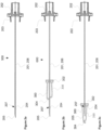
- a catheter hub 100 of an open IV catheter system comprises a longitudinal and tubular catheter 101 at its distal end.
- the catheter 101 is, in accordance with above, intended to be inserted into a blood vessel of a patient.
- the catheter 101 is attached to a catheter hub body 102 at its proximal end, such that the catheter extends distally from the catheter hub body 102.
- the lumen of the catheter 101 is in fluid communication with a distal catheter hub cavity 103.
- the catheter hub body 102 is preferably made through injection molding, and then of a rigid plastic material suitable for injection molding and connection and interaction with other parts of the system.
- a suitable material is polycarbonate or a copolymer of polycarbonate and polyester.
- an open connector 104 is provided on a catheter hub body 102.
- the open connector 104 extends laterally from the catheter hub body 102.
- the open connector 104 may for example be tubular.
- the open connector 104 may be a luer fitting, such as a luer lock or luer slip, adapted to receive a syringe or tubing set in a known manner.
- the open connector 104 may have a lid, such as an injection port cap. The lid may be spring force operated.
- the open connector 104 connects to a bifunctional valve 106 in the distal catheter hub cavity 103, such that a tube or syringe may be connected to the tube connector 104 allowing for infusion through the open tube connector 104 into a proximal catheter hub cavity 107, further to the catheter 101 and finally into the blood stream of the patient, when there is no needle through the bifunctional valve 106 and catheter 101.
- the distal catheter hub cavity 103 ends proximally in a bifunctional valve 106.
- This bifunctional valve 106 has a central through-channel, which may be penetrated by a needle 201 of a needle hub 200, in accordance with Fig. 1a.
- the bifunctional valve 106 When the needle 201 has been withdrawn from the catheter hub 100, the bifunctional valve 106 will keep said through channel open, such that the distal catheter hub cavity 103 is in contact with the proximal catheter hub cavity 107.
- the bifunctional valve 106 is preferably of a suitable rubber material or silicone.
- the proximal catheter hub cavity 107 is formed by the tubular wall of the catheter hub body 102 and a distal end wall in form of the proximal end wall of the bifunctional valve 106.
- This proximal catheter hub cavity 107 extending distally into the catheter hub body 102, is adapted in size and shape to house the needle shield 300, as disclosed in Fig. 1a.
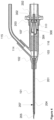
- the needle hub 200 comprises a needle 201 extending distally from a needle hub body 202 with a needle shaft 206, a needle tip 205, a bulge 204 and a high friction surface part 207 at its distal end zone, as seen in figures 2a to 2c .
- the high friction surface part 207 may at least partly be applied on the bulge 204 and/or proximally of the bulge 204, i.e. closer to the needle hub body 202 than the bulge 204.
- the high friction surface part 207 may also cover the bulge 204, and extend proximally and/or distally of the bulge 204. To facilitate skin penetration, the high friction surface part 207 does however not cover the needle tip 205 and/or the part of the needle 201 extending distally beyond a catheter on an IV catheter system in a ready-to-use state.
- the needle bulge 204 is a short section of the needle, where the radius of the bulge 204 is larger than that of the needle shaft 206. This may be achieved by a slight local deformation of the needle shaft 206. By a slight flattening of two opposing sides of the needle shaft 206, perpendicular to the length axis of the needle shaft 206, increased radius transitions between the flattened areas will protrude distally from the needle shaft and provide the bumps of the needle bulge 206, as seen in figures 2a to 2c .
- the needle bulge 204 may also be obtained by for example providing the needle shaft 206 with a weld.
- the needle bulge 204 area has a high friction surface part 207, covering at least the needle bulge 204, and may extend proximally and/or distally of the bulge 204 along the needle shaft 206.
- a needle system 500 comprising a needle hub 200, wherein the needle hub 200 comprises a needle 201 extending distally from a needle hub body 202 with the needle bulge 204 at its distal end zone having a high friction surface part 207.
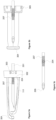
- the needle shield 300 comprises a base plate 301.
- the base plate 301 is provided with a hole 302, extending there through, i.e. from the proximal side of the base plate 301 to the distal side of the base plate 301.
- the hole 302 is arranged centrally on the base plate 301, such that arrangement of needle 201 through said hole 302 is facilitated while the needle 201 is arranged in accordance with the ready position of the catheter instrument.
- At least one resilient arm 310 is extending distally from an attachment point at said base plate 301.
- the attachment point is located at the periphery of the base plate 301.
- the resilient arm 310 has a resting state, from which it may be urged to yield free passage for the needle 201 through said hole 302 in an axial direction of said base plate 301 in a tension state.
- This released resting state is disclosed in Fig. 2c .
- the resilient arm 310 is in its tension state when the catheter instrument 100 is in its ready position, in accordance with Fig. 1a.
- the resilient arm 310 is adapted for clamping a needle tip 205 of a needle 201 extending through the hole 302 when the resilient arm 310 is in said resting state. For this reason, a straight imaginary line extending longitudinally through said hole 302 in the axial direction of said base plate 301 coincides with said at least one resilient arm 310 when said resilient arm 310 is in said resting state.
- the needle shield 300 may comprise one, two, three or more tongues 303, which extend proximally from the lateral circular periphery of the base plate 302.
- the tongues 303 are, in accordance with above, resilient, whereby they are resiliently striving from a compressed state towards an expanded state. In the assembled state within the proximal catheter hub cavity 107, the tongues 303 are somewhat compressed, to exercise a force on the inner walls of the catheter hub 100.
- the needle shield 300 is thereby held therein, i.e. a constant spatial relationship between the needle shield 300 and the catheter hub 100 is provided.
- a plurality of tongues 303 may be evenly spread at the periphery of the base plate 302, whereby each tongue 303 is contacting the inner surface of the catheter hub 100 with essentially the same force.
- the tongues 303 may comprise a protuberance 305 extending in a direction essentially perpendicular to the central axis or laterally of the needle shield 300.
- the diameter of the base plate 302 in a transversal plane intersecting the protuberances 305 may be greater than the diameter of the proximal catheter hub cavity 107, and specifically the proximal opening thereof, along a transversal plane. Then the needle shield 300 may be compressed, due to the flexibility of the tongues 303, such that it may be inserted into the proximal catheter hub cavity 107 in a compressed state.
- the protuberances 305 on the tongues 303 then exerts a retaining radially outwards directed pressure on the inner wall of the proximal catheter hub cavity 107.
- the ridge 108 of at the opening of the proximal catheter hub cavity 107 then maintains the needle shield 300 within the cavity, until the needle 201 bulge 204 pulls the stopping element proximally to the needle shield, whereby the pressure of the protuberances 305 on the inner walls of the proximal catheter hub cavity 107 is overcome and the also the protuberances 305 are pressed inwardly beyond the ridge 108 to safely release the needle shield 300 from the proximal catheter hub cavity 107.
- the ridge 108 is somewhat slanting distally and/or proximally.
- the protuberances 305 are in the same way slanting distally and/or proximally.
- the slanting of the protuberances is sharper in the proximal direction than in the distal direction, whereby the needle shield 300 may be smoothly inserted into the proximal catheter hub cavity 107, retained with a snap action when the proximal side of the protuberances pass distally beyond the ridge 108, and also maintained more securely due to the sharper slanting at the proximal zone.
- a shielded needle system 600 comprising a needle hub 200 and a needle shield 300.
- the needle hub 200 comprises a needle 201 extending distally from a needle hub body 202 with the needle bulge 204 at its distal end zone having a high friction surface part 207.
- the needle shield 300 is mounted on the needle, the needle shaft 206 extending through the hole of the needle shield base plate, the base plate being at the proximal end and the at least on resilient arm 310 at the distal end.
- the needle shield is mounted on the needle and located between the needle hub 200 and needle bulge 204.
- the high friction surface part 207 is intended to cover the needle bulge 204, and extending proximally and possibly distally of the bulge 204, along the needle shaft 206.
- the length of the high friction surface part 207, from its distal end to its proximal end, may vary due to factors such as the diameter of the needle, but is in the range of 0.2 to 20 mm, preferably 0.5 to 5 mm.
- the friction coefficient between the normally polished steel alloy of the needle and a fatter plastic can be lower than 0.05 ( ⁇ s ). This is a positive property for optimal operation of the needle shield, ensuring smooth and quiet needle movement through the through hole of the needle shield base plate 302.
- the modulus of elasticity of a polymer body such as the needle shield 300 is low (polymer (PC) 2300 MPa or (LCP) 7000 MPa), resulting in that with a polished (low friction) needle bulge, there is a risk of the needle shield 300 deforming enough to be forced past the needle bulge 204.
- PC polymer
- LCP low friction
- the friction coefficient is increased up to 20-fold between the needle shield 300 and the high friction surface part 207 of the needle bulge 204. This greatly increases the force required for the needle shield 300 to be forced past the needle bulge 204.
- the surface roughness of a polished needle for medical purposes is 0.2 R a .
- the surface roughness of the high friction surface part 207 is selected to be above 0.2 R a , such as 0.25 to 25 R a , and as defined in the invention, 0.25 to 10 R a , and even more preferably from 0.5 to 5 R a , such as 0.75 to 3 Ra.
- the surface roughness is adapted not to interact with the catheter, upon withdrawal of the needle hub 200 from the catheter hub 100, while simultaneously allowing for increased interaction between the needle shield 300 and the needle 201 of the needle hub 200, and more precisely the bulge 204 and the needle shield 300, such that needle shield 300 will be better retained on the needle 201.
- the needle shield 300 By extending the high friction surface part 207 along the needle shaft 206, proximally of the needle bulge 204, the needle shield 300 will be subjected to high friction contact with the needle shaft 206 already before the needle shield base plate 302 interacts with the needle bulge 204. This is even more pronounced if the needle shield 300 experiences any lateral force or is tilting slightly in relation to the length axis of the needle shaft 206. This will result in increased drag between the needle shield 300 and the needle shaft 206 just before the needle shield base plate 302 makes contact with the needle bulge 204, providing part of the force required to release the needle shield 300 from the catheter hub 100, making it easier for the needle bulge 204 to release the needle shield 300.
- the high friction surface part 207 can be achieved by processes, such as sandblasting, etching (chemical process), erosion, electron beam surface treatment, plasma treatment, electrical discharge machining and laser texturing.
- the high friction surface part 207 could be achieved by adding a surface layer or surface film, such as a high-friction coating or layer, on the area of the high friction surface part 207.
- the needle shield 300 is intended to be arranged on the needle 201 of the needle hub 200, which in turn is intended to be arranged in the catheter hub 100.
- the needle 201 penetrates the bifunctional valve 106, and extends through the catheter 101.
- the needle 201 extends just beyond the distal end of the catheter 101, such that skin and blood vessel penetration is facilitated.
- the needle shield 300 is arranged in the proximal catheter hub cavity 107, with arms 301 thereof forced laterally by needle 201.
- the needle shield 300 preferably does not extend proximally of the proximal end of the catheter hub 100, but is instead entirely housed in the proximal catheter hub cavity 107 of the catheter hub 100.
- the needle hub body 202 of the needle hub 200 may cooperate with the catheter hub body 102 of the catheter hub 100, without intermediary structures, such as the needle shield 300. This may be accomplished through a distal connective flange 203 on the needle hub 200. The distal connective flange 203 may then house the distal end of the catheter body 102 of the catheter hub 100. This connection may be a snap fit.
- the needle hub body 202 has a distal cavity for housing a part of the needle shield 300, while still being adapted to be connectable to the catheter hub body 102. In this position the needle shield 300 is held in place in the proximal catheter hub cavity 107 through interaction between a needle shield base plate 302 and the inner tubular wall of the catheter hub body 102.
- a circumferential ridge 108 may be formed at the opening of the proximal catheter hub cavity 107.
- the base plate 302 is provided with a centrally arranged through hole, such that the needle 200 may run freely therein.
- the needle hub 200 When withdrawing the needle hub 200 from the catheter hub 100, after the catheter 101 has been securely placed inside the blood vessel of the patient, the needle hub 200 will firstly be disconnected from the cooperation between the catheter hub body 102 and the needle hub body 202, such as through release of the connective flange 203 from the circumference of the catheter body 102. Then the needle 201 travels proximally within the catheter 101, until the needle tip 205 of the needle 201 exits the catheter 101 and enters the catheter hub body 102. When entering the catheter hub body 102, the needle tip 205 of the needle 201 will continue proximally into the distal catheter hub cavity 103 and further through the bifunctional valve 106.
- the needle tip 205 of the needle 201 exits the bifunctional valve 106 on the proximal side thereof, the needle tip 205 of the needle 201 enters the proximal catheter hub cavity 107 of the catheter hub 100, wherein the needle shield 300 is securingly interacting with the inner tubular wall of the catheter hub body 102.
- the arms 310 will snap centrally to cover the needle tip 205 of the needle 200.
Landscapes
- Health & Medical Sciences (AREA)
- Life Sciences & Earth Sciences (AREA)
- Animal Behavior & Ethology (AREA)
- General Health & Medical Sciences (AREA)
- Biomedical Technology (AREA)
- Heart & Thoracic Surgery (AREA)
- Hematology (AREA)
- Engineering & Computer Science (AREA)
- Veterinary Medicine (AREA)
- Anesthesiology (AREA)
- Public Health (AREA)
- Biophysics (AREA)
- Pulmonology (AREA)
- Vascular Medicine (AREA)
- Infusion, Injection, And Reservoir Apparatuses (AREA)
- Media Introduction/Drainage Providing Device (AREA)
Claims (13)
- IV-Kathetersystem, umfassend:einen Katheteransatz (100) umfassend: einen röhrenförmigen Katheter (101), mit einem Lumen, der am proximalen Ende des Katheteransatzkörpers (102) befestigt ist, mit einem Katheteransatzhohlraum (103, 107), der in Fluidverbindung mit dem Lumen des röhrenförmigen Katheters (101) steht;einen Nadelansatz (200) umfassend: eine Nadel (201), die sich distal von einem Nadelansatzkörper (202) erstreckt, wobei die Nadel (201) eine Ausbuchtung (204) und einen Oberflächenabschnitt mit hoher Reibung (207) an ihrem distalen Endbereich aufweist;wobei der Oberflächenabschnitt mit hoher Reibung (207) zumindest auf der Ausbuchtung (204) aufgebracht ist und sich proximal und distal der Ausbuchtung (204) entlang eines Abschnitts der Metalllegierung eines Nadelschafts (206) erstreckt und eine Oberflächenrauheit in einem Bereich von 0,25 bis 10 Ra aufweist;einen Nadelschutz (300), der aus einem Polymer mit einem niedrigen Elastizitätsmodul hergestellt ist und zumindest einen elastischen Arm (310) umfasst, der sich distal von einer Grundplatte (302) erstreckt, wobei die Grundplatte (302) eine Durchgangsöffnung zur Aufnahme der Nadel (201) aufweist;wobei der Nadelansatz (200) im Katheteransatz (100) angeordnet ist, sodass die Nadel (201) gleitend durch das Lumen des Katheters (101) angeordnet ist, sodass die Nadel (201) proximal aus dem Katheteransatz (100) herausgezogen werden kann;wobei der Nadelschutz (300) in dem Katheteransatzhohlraum (103, 107) durch Zusammenwirken zwischen dem Nadelschutz (300) und einer Innenwand des Katheteransatzes (100) in dem Katheteransatzhohlraum (103, 107) und auf der Nadel (201) so gehalten wird, dass der zumindest eine Arm (310) auf der Nadel (201) aufliegt und durch diese federbelastet ist, und die Nadel (201) in einem zusammengebauten Zustand gleitend innerhalb der Durchgangsöffnung der Grundplatte (302) angeordnet ist; undwobei der Außendurchmesser der Nadelausbuchtung (204) größer ist als der Innendurchmesser der Durchgangsöffnung der Grundplatte (302), sodass, wenn der Nadelansatz (200) aus dem Katheteransatz (100) herausgezogen wird, der Kontakt zwischen der Nadelausbuchtung (204) und der Grundplatte (302) eine Kraft bereitstellt, um den Nadelschutz (300) vom Katheteransatz (100) zu lösen, wobei der zumindest eine elastische Arm (310) die Spitze der Nadel (201) in einem gelösten Zustand abdeckt.
- IV-Kathetersystem nach Anspruch 1, wobei der Oberflächenabschnitt mit hoher Reibung (207) auf der Nadelausbuchtung (204) aufgebracht ist.
- IV-Kathetersystem nach einem der vorhergehenden Ansprüche, wobei der Oberflächenabschnitt mit hoher Reibung (207) ein Abschnitt der Metalllegierung des Nadelschafts (206) ist, der durch Verfahren wie Sandstrahlen, Ätzen (chemisches Verfahren), Erosion, Elektronenstrahl-Oberflächenbehandlung, Plasmabehandlung, Funkenerosion, Beschichtung und Lasertexturierung aufgeraut wurde.
- IV-Kathetersystem nach einem der vorhergehenden Ansprüche, wobei die Länge des Oberflächenabschnitts mit hoher Reibung (207) von seinem distalen Ende zu seinem proximalen Ende 0,5 bis 20 mm, vorzugsweise 1 bis 5 mm beträgt.
- IV-Kathetersystem nach einem der vorhergehenden Ansprüche, wobei das proximale Ende des Katheteransatzkörpers (102) im zusammengebauten Zustand mit dem distalen Ende des Nadelansatzkörpers (202) zusammenwirkt.
- IV-Kathetersystem nach einem der vorhergehenden Ansprüche, wobei ein distaler Verbindungsflansch (203) des Nadelansatzkörpers (202) mit der äußeren proximalen Oberfläche des Katheteransatzkörpers (102) in haltender Weise zusammenwirkt.
- IV-Kathetersystem nach einem der vorhergehenden Ansprüche, wobei der Randbereich der Grundplatte (302) mit 3 bis 5 elastischen Zungen (303) versehen ist.
- IV-Kathetersystem nach einem der vorhergehenden Ansprüche, wobei die Zungen (303) gleichmäßig entlang des Randbereichs der Grundplatte (302) verteilt sind.
- IV-Kathetersystem nach einem der vorhergehenden Ansprüche, wobei die zumindest eine Zunge (303) mit einem sich seitwärts erstreckenden Vorsprung (305) versehen ist.
- IV-Kathetersystem nach einem der vorhergehenden Ansprüche, wobei der Nadelschutz (300) ein monolithischer Kunststoffkörper ist, wobei das Kunststoffmaterial des Nadelschutzes (300) aus der Gruppe ausgewählt ist, die aus POM, PBTP, PMMA, ABS, SAN, ASA, PS, SB, LCP, PA, PSU, PEI, PC, PPO und/oder PPO/SB besteht.
- Nadelansatz (200) umfassend: eine Nadel (201), die sich distal von einem Nadelansatzkörper (202) erstreckt, wobei die Nadel (201) eine Ausbuchtung (204) und einen Oberflächenabschnitt mit hoher Reibung (207) an ihrem distalen Endbereich aufweist, wobei der Oberflächenabschnitt mit hoher Reibung (207) zumindest auf der Ausbuchtung (204) aufgebracht ist und sich proximal und distal der Ausbuchtung (204) entlang eines Abschnitts der Metalllegierung eines Nadelschafts (206) erstreckt und eine Oberflächenrauheit in einem Bereich von 0,25 bis 10 Ra aufweist.
- Nadelansatz (200) nach Anspruch 11, wobei der Oberflächenabschnitt mit hoher Reibung (207) auf der Ausbuchtung (204) aufgebracht ist.
- Abgeschirmtes Nadelsystem (600) umfassend einen Nadelansatz (200) nach einem der Ansprüche 11 oder 12, und einen Nadelschutz (300);
der Nadelschutz (300) umfassend: zumindest einen elastischen Arm (310), der sich distal von einer Grundplatte (302) erstreckt, welche Grundplatte (302) eine Durchgangsöffnung zur Aufnahme der Nadel (201) aufweist; und wobei der Nadelschutz (300) zwischen der Ausbuchtung (204) und der distalen Seite des Nadelansatzkörpers (202) angeordnet ist.
Applications Claiming Priority (2)
| Application Number | Priority Date | Filing Date | Title |
|---|---|---|---|
| SE1550001 | 2015-01-02 | ||
| PCT/EP2015/081459 WO2016107922A1 (en) | 2015-01-02 | 2015-12-30 | Needle hub and iv catheter system comprising such needle hub |
Publications (3)
| Publication Number | Publication Date |
|---|---|
| EP3240601A1 EP3240601A1 (de) | 2017-11-08 |
| EP3240601C0 EP3240601C0 (de) | 2025-04-16 |
| EP3240601B1 true EP3240601B1 (de) | 2025-04-16 |
Family
ID=55027779
Family Applications (1)
| Application Number | Title | Priority Date | Filing Date |
|---|---|---|---|
| EP15817431.8A Active EP3240601B1 (de) | 2015-01-02 | 2015-12-30 | Nadelträger und iv-kathetersystem mit solch einem nadelträger |
Country Status (9)
| Country | Link |
|---|---|
| US (1) | US11406794B2 (de) |
| EP (1) | EP3240601B1 (de) |
| JP (3) | JP2018505713A (de) |
| KR (1) | KR20170102918A (de) |
| CN (3) | CN110074792A (de) |
| AU (1) | AU2015373377A1 (de) |
| CA (1) | CA2972544A1 (de) |
| ES (1) | ES3027187T3 (de) |
| WO (1) | WO2016107922A1 (de) |
Families Citing this family (30)
| Publication number | Priority date | Publication date | Assignee | Title |
|---|---|---|---|---|
| ES2975734T3 (es) | 2015-01-29 | 2024-07-12 | Becton Dickinson Co | Catéter integrado de inserción rápida |
| US10639431B2 (en) * | 2015-08-07 | 2020-05-05 | Vigmed Ab | Needle shielding system |
| WO2017151052A1 (en) * | 2016-03-04 | 2017-09-08 | Vigmed Ab | Blood collection device |
| EP3525842A1 (de) * | 2016-10-13 | 2019-08-21 | Sanofi-Aventis Deutschland GmbH | Arzneimittelverabreichungsvorrichtung |
| KR200487150Y1 (ko) * | 2018-01-23 | 2018-08-13 | 코박메드 주식회사 | 니들의 결합력이 우수한 캐뉼라 |
| KR200491366Y1 (ko) | 2018-01-24 | 2020-03-26 | 주식회사 유니메딕스 | Iv 카테터 고정부재 |
| TWI734958B (zh) | 2018-03-19 | 2021-08-01 | 日商泰爾茂股份有限公司 | 穿刺針及導管組合體 |
| US11547525B2 (en) * | 2018-06-06 | 2023-01-10 | Tel Hashomer Medical Research Infrastructure And Services Ltd. | Endotracheal tube cleaning device system and method |
| KR102221456B1 (ko) * | 2019-01-09 | 2021-03-02 | (주)지 메디 | 안전성을 강화한 의료용 혈관 카테터 세트 |
| EP4028104A4 (de) | 2019-09-10 | 2023-12-13 | MedSource International LLC | Intravenöse kathetervorrichtung |
| KR20220060550A (ko) | 2019-09-10 | 2022-05-11 | 바드 액세스 시스템즈, 인크. | 신속 삽입 중앙 카테터 및 그 방법(rapidly inserted central catheter and methods thereof) |
| KR102883827B1 (ko) | 2019-09-24 | 2025-11-07 | 바드 액세스 시스템즈, 인크. | 일체형 급성 중앙 정맥 카테터 및 말초 삽입 정맥 카테터(an integrated acute central venous catheter and peripherally inserted venous catheter) |
| WO2021081434A1 (en) | 2019-10-25 | 2021-04-29 | Bard Access Systems, Inc. | Guidewire-management devices and methods thereof |
| US11826526B2 (en) | 2020-01-23 | 2023-11-28 | Bard Access Systems, Inc. | Splitable catheter docking station system and method |
| CN215608659U (zh) | 2020-03-13 | 2022-01-25 | 巴德阿克塞斯系统股份有限公司 | 导丝管理装置 |
| CA3172391A1 (en) | 2020-03-13 | 2021-09-16 | Bard Access Systems, Inc. | Guidewire-management devices and methods thereof |
| US12042611B2 (en) * | 2020-03-23 | 2024-07-23 | Becton, Dickinson And Company | Needle shield |
| CN113546276A (zh) | 2020-04-23 | 2021-10-26 | 巴德阿克塞斯系统股份有限公司 | 包括导管组件的可快速插入的中心导管及其方法 |
| US11819638B2 (en) | 2020-05-21 | 2023-11-21 | Bard Access Systems, Inc. | Rapidly insertable central catheters including catheter assemblies and methods thereof |
| JP7760535B2 (ja) | 2020-06-29 | 2025-10-27 | バード・アクセス・システムズ,インコーポレーテッド | 患者の血管内腔への直接挿入のためのカテーテルアセンブリ |
| CA3186461A1 (en) | 2020-06-29 | 2022-01-06 | Bard Access Systems, Inc. | Rapidly insertable central catheters including assemblies |
| US12171970B2 (en) * | 2020-10-12 | 2024-12-24 | Becton, Dickinson And Company | Catheter assembly with directional port opening |
| KR20230098227A (ko) | 2020-10-28 | 2023-07-03 | 바드 액세스 시스템즈, 인크. | 강화 시스템이 구비된 카테터 배치 시스템 (catheter placement system with stiffening system) |
| US12472331B2 (en) | 2020-12-03 | 2025-11-18 | Bard Access Systems, Inc. | Needle tip blunting using a length of a guidewire |
| KR20230121775A (ko) | 2020-12-17 | 2023-08-21 | 바드 액세스 시스템즈, 인크. | 신속 삽입 가능 중심 카테터, 조립체, 및 그 방법(rapidlyinsertable central catheters, assemblies, and methods thereof) |
| CN114642784B (zh) | 2020-12-21 | 2025-12-02 | 巴德阿克塞斯系统股份有限公司 | 导管插入系统和导管放置系统 |
| CA3203907A1 (en) | 2020-12-21 | 2022-06-30 | Bard Access Systems, Inc. | Optimized structural support in catheter insertion systems |
| US12337123B2 (en) | 2021-05-06 | 2025-06-24 | Medsource Labs, Llc | Safety intravenous cannula |
| US12186497B2 (en) | 2022-01-14 | 2025-01-07 | Medsource International Llc | Intravenous cannula |
| KR102448816B1 (ko) | 2022-03-31 | 2022-09-30 | (주)카이로스 | 니들 홀더 |
Family Cites Families (17)
| Publication number | Priority date | Publication date | Assignee | Title |
|---|---|---|---|---|
| US4869259A (en) * | 1988-05-17 | 1989-09-26 | Vance Products Incorporated | Echogenically enhanced surgical instrument and method for production thereof |
| US4952207A (en) * | 1988-07-11 | 1990-08-28 | Critikon, Inc. | I.V. catheter with self-locating needle guard |
| US5558651A (en) * | 1990-04-20 | 1996-09-24 | Becton Dickinson And Company | Apparatus and method for a needle tip cover |
| US5215528C1 (en) * | 1992-02-07 | 2001-09-11 | Becton Dickinson Co | Catheter introducer assembly including needle tip shield |
| US5257980A (en) * | 1993-04-05 | 1993-11-02 | Minimed Technologies, Ltd. | Subcutaneous injection set with crimp-free soft cannula |
| US6117108A (en) | 1997-08-20 | 2000-09-12 | Braun Melsungen Ag | Spring clip safety IV catheter |
| US6394979B1 (en) * | 2000-06-09 | 2002-05-28 | Inviro Medical Devices Ltd. | Cannula for use with a medical syringe |
| US20050075609A1 (en) | 2003-10-01 | 2005-04-07 | Latona Patrick C. | Protective needle clips |
| US7988664B2 (en) * | 2004-11-01 | 2011-08-02 | Tyco Healthcare Group Lp | Locking clip with trigger bushing |
| CN201356557Y (zh) * | 2009-01-17 | 2009-12-09 | 山东新华安得医疗用品有限公司 | 安全采血针持针器 |
| US8474300B2 (en) * | 2009-07-20 | 2013-07-02 | Becton, Dickinson And Company | Methods to provide a feature on a needle |
| SE535169C2 (sv) * | 2010-04-13 | 2012-05-08 | Vigmed Ab | Skyddsanordning av polymer för en kateternålspets |
| PL2600925T3 (pl) * | 2010-08-05 | 2021-12-06 | B. Braun Melsungen Ag | Urządzenie zabezpieczające igłę i zespół |
| US9126012B2 (en) * | 2011-10-06 | 2015-09-08 | Becton, Dickinson And Company | Intravenous catheter with duckbill valve |
| SE537262C2 (sv) | 2012-06-15 | 2015-03-17 | Vigmed Ab | Ett stängt IV-katetersystem innefattande en nålskyddsanordning |
| WO2014107133A1 (en) | 2013-01-03 | 2014-07-10 | Vigmed Ab | Spring clip needle guard |
| CN104043186B (zh) * | 2013-03-15 | 2018-11-13 | B.布劳恩梅尔松根股份公司 | 具有可擦拭血流阻断器的导管组件及相关方法 |
-
2015
- 2015-12-30 CN CN201811638458.4A patent/CN110074792A/zh active Pending
- 2015-12-30 EP EP15817431.8A patent/EP3240601B1/de active Active
- 2015-12-30 CA CA2972544A patent/CA2972544A1/en not_active Abandoned
- 2015-12-30 CN CN201580072030.6A patent/CN107106817A/zh active Pending
- 2015-12-30 ES ES15817431T patent/ES3027187T3/es active Active
- 2015-12-30 KR KR1020177021321A patent/KR20170102918A/ko not_active Withdrawn
- 2015-12-30 US US15/541,273 patent/US11406794B2/en active Active
- 2015-12-30 JP JP2017534706A patent/JP2018505713A/ja active Pending
- 2015-12-30 CN CN202211156553.7A patent/CN115715842A/zh active Pending
- 2015-12-30 AU AU2015373377A patent/AU2015373377A1/en not_active Abandoned
- 2015-12-30 WO PCT/EP2015/081459 patent/WO2016107922A1/en not_active Ceased
-
2020
- 2020-09-01 JP JP2020146455A patent/JP7309674B2/ja active Active
-
2022
- 2022-07-08 JP JP2022110707A patent/JP2022130737A/ja active Pending
Also Published As
| Publication number | Publication date |
|---|---|
| EP3240601C0 (de) | 2025-04-16 |
| AU2015373377A1 (en) | 2017-07-13 |
| JP2021006257A (ja) | 2021-01-21 |
| CA2972544A1 (en) | 2016-07-07 |
| CN107106817A (zh) | 2017-08-29 |
| EP3240601A1 (de) | 2017-11-08 |
| WO2016107922A1 (en) | 2016-07-07 |
| CN110074792A (zh) | 2019-08-02 |
| JP2022130737A (ja) | 2022-09-06 |
| US20170361070A1 (en) | 2017-12-21 |
| BR112017014247A2 (pt) | 2018-02-20 |
| ES3027187T3 (en) | 2025-06-13 |
| JP2018505713A (ja) | 2018-03-01 |
| CN115715842A (zh) | 2023-02-28 |
| US11406794B2 (en) | 2022-08-09 |
| BR112017014247A8 (pt) | 2022-08-16 |
| JP7309674B2 (ja) | 2023-07-18 |
| KR20170102918A (ko) | 2017-09-12 |
Similar Documents
| Publication | Publication Date | Title |
|---|---|---|
| EP3240601B1 (de) | Nadelträger und iv-kathetersystem mit solch einem nadelträger | |
| EP2861292B1 (de) | Abschirmvorrichtung und befestigungsanordnung für nadelspitzen | |
| EP3283146B1 (de) | Nadelspitzenabschirmungsvorrichtung und katheternabe dafür | |
| EP3609562B1 (de) | Gefässzugangsvorrichtung | |
| EP2544750B1 (de) | Katheter-vorrichtung mit einem haubenelement | |
| WO2015167385A1 (en) | Catheter instrument and catheter hub therefore | |
| WO2017151052A1 (en) | Blood collection device | |
| EP3331593B1 (de) | Nadelschutzsystem | |
| AU2020369020B2 (en) | A catheter device comprising a levering member | |
| JPH0928811A (ja) | 血管内留置カテーテル組立体 | |
| EP3787511B1 (de) | Durch zusammendrücken aktiviertes blutentnahmeset | |
| BR112017014247B1 (pt) | Sistema de cateter iv compreendendo um cubo de cateter | |
| HK1243012A1 (en) | Needle tip shielding device and catheter hub therefor |
Legal Events
| Date | Code | Title | Description |
|---|---|---|---|
| STAA | Information on the status of an ep patent application or granted ep patent |
Free format text: STATUS: THE INTERNATIONAL PUBLICATION HAS BEEN MADE |
|
| PUAI | Public reference made under article 153(3) epc to a published international application that has entered the european phase |
Free format text: ORIGINAL CODE: 0009012 |
|
| STAA | Information on the status of an ep patent application or granted ep patent |
Free format text: STATUS: REQUEST FOR EXAMINATION WAS MADE |
|
| 17P | Request for examination filed |
Effective date: 20170704 |
|
| AK | Designated contracting states |
Kind code of ref document: A1 Designated state(s): AL AT BE BG CH CY CZ DE DK EE ES FI FR GB GR HR HU IE IS IT LI LT LU LV MC MK MT NL NO PL PT RO RS SE SI SK SM TR |
|
| AX | Request for extension of the european patent |
Extension state: BA ME |
|
| DAV | Request for validation of the european patent (deleted) | ||
| DAX | Request for extension of the european patent (deleted) | ||
| STAA | Information on the status of an ep patent application or granted ep patent |
Free format text: STATUS: EXAMINATION IS IN PROGRESS |
|
| 17Q | First examination report despatched |
Effective date: 20190813 |
|
| RAP1 | Party data changed (applicant data changed or rights of an application transferred) |
Owner name: GREINER BIO-ONE GMBH |
|
| P01 | Opt-out of the competence of the unified patent court (upc) registered |
Effective date: 20230526 |
|
| GRAP | Despatch of communication of intention to grant a patent |
Free format text: ORIGINAL CODE: EPIDOSNIGR1 |
|
| STAA | Information on the status of an ep patent application or granted ep patent |
Free format text: STATUS: GRANT OF PATENT IS INTENDED |
|
| INTG | Intention to grant announced |
Effective date: 20241115 |
|
| RIN1 | Information on inventor provided before grant (corrected) |
Inventor name: HIVERT, MAGNUS |
|
| GRAS | Grant fee paid |
Free format text: ORIGINAL CODE: EPIDOSNIGR3 |
|
| GRAA | (expected) grant |
Free format text: ORIGINAL CODE: 0009210 |
|
| STAA | Information on the status of an ep patent application or granted ep patent |
Free format text: STATUS: THE PATENT HAS BEEN GRANTED |
|
| AK | Designated contracting states |
Kind code of ref document: B1 Designated state(s): AL AT BE BG CH CY CZ DE DK EE ES FI FR GB GR HR HU IE IS IT LI LT LU LV MC MK MT NL NO PL PT RO RS SE SI SK SM TR |
|
| REG | Reference to a national code |
Ref country code: GB Ref legal event code: FG4D |
|
| REG | Reference to a national code |
Ref country code: CH Ref legal event code: EP Ref country code: DE Ref legal event code: R096 Ref document number: 602015091457 Country of ref document: DE |
|
| REG | Reference to a national code |
Ref country code: IE Ref legal event code: FG4D |
|
| U01 | Request for unitary effect filed |
Effective date: 20250508 |
|
| REG | Reference to a national code |
Ref country code: ES Ref legal event code: FG2A Ref document number: 3027187 Country of ref document: ES Kind code of ref document: T3 Effective date: 20250613 |
|
| P04 | Withdrawal of opt-out of the competence of the unified patent court (upc) registered |
Free format text: CASE NUMBER: APP_22422/2025 Effective date: 20250513 |
|
| U07 | Unitary effect registered |
Designated state(s): AT BE BG DE DK EE FI FR IT LT LU LV MT NL PT RO SE SI Effective date: 20250515 |
|
| PG25 | Lapsed in a contracting state [announced via postgrant information from national office to epo] |
Ref country code: NO Free format text: LAPSE BECAUSE OF FAILURE TO SUBMIT A TRANSLATION OF THE DESCRIPTION OR TO PAY THE FEE WITHIN THE PRESCRIBED TIME-LIMIT Effective date: 20250716 Ref country code: GR Free format text: LAPSE BECAUSE OF FAILURE TO SUBMIT A TRANSLATION OF THE DESCRIPTION OR TO PAY THE FEE WITHIN THE PRESCRIBED TIME-LIMIT Effective date: 20250717 |
|
| PG25 | Lapsed in a contracting state [announced via postgrant information from national office to epo] |
Ref country code: PL Free format text: LAPSE BECAUSE OF FAILURE TO SUBMIT A TRANSLATION OF THE DESCRIPTION OR TO PAY THE FEE WITHIN THE PRESCRIBED TIME-LIMIT Effective date: 20250416 |
|
| PG25 | Lapsed in a contracting state [announced via postgrant information from national office to epo] |
Ref country code: HR Free format text: LAPSE BECAUSE OF FAILURE TO SUBMIT A TRANSLATION OF THE DESCRIPTION OR TO PAY THE FEE WITHIN THE PRESCRIBED TIME-LIMIT Effective date: 20250416 |
|
| PG25 | Lapsed in a contracting state [announced via postgrant information from national office to epo] |
Ref country code: RS Free format text: LAPSE BECAUSE OF FAILURE TO SUBMIT A TRANSLATION OF THE DESCRIPTION OR TO PAY THE FEE WITHIN THE PRESCRIBED TIME-LIMIT Effective date: 20250716 |
|
| PG25 | Lapsed in a contracting state [announced via postgrant information from national office to epo] |
Ref country code: IS Free format text: LAPSE BECAUSE OF FAILURE TO SUBMIT A TRANSLATION OF THE DESCRIPTION OR TO PAY THE FEE WITHIN THE PRESCRIBED TIME-LIMIT Effective date: 20250816 |