EP3239015B1 - Kraftgeregelte spurführung für ein schienenfahrzeug - Google Patents
Kraftgeregelte spurführung für ein schienenfahrzeug Download PDFInfo
- Publication number
- EP3239015B1 EP3239015B1 EP17164999.9A EP17164999A EP3239015B1 EP 3239015 B1 EP3239015 B1 EP 3239015B1 EP 17164999 A EP17164999 A EP 17164999A EP 3239015 B1 EP3239015 B1 EP 3239015B1
- Authority
- EP
- European Patent Office
- Prior art keywords
- rail vehicle
- actuator unit
- actuating force
- axle
- elastic bearing
- Prior art date
- Legal status (The legal status is an assumption and is not a legal conclusion. Google has not performed a legal analysis and makes no representation as to the accuracy of the status listed.)
- Active
Links
Images

Classifications
-
- B—PERFORMING OPERATIONS; TRANSPORTING
- B61—RAILWAYS
- B61F—RAIL VEHICLE SUSPENSIONS, e.g. UNDERFRAMES, BOGIES OR ARRANGEMENTS OF WHEEL AXLES; RAIL VEHICLES FOR USE ON TRACKS OF DIFFERENT WIDTH; PREVENTING DERAILING OF RAIL VEHICLES; WHEEL GUARDS, OBSTRUCTION REMOVERS OR THE LIKE FOR RAIL VEHICLES
- B61F5/00—Constructional details of bogies; Connections between bogies and vehicle underframes; Arrangements or devices for adjusting or allowing self-adjustment of wheel axles or bogies when rounding curves
- B61F5/38—Arrangements or devices for adjusting or allowing self- adjustment of wheel axles or bogies when rounding curves, e.g. sliding axles, swinging axles
- B61F5/383—Adjustment controlled by non-mechanical devices, e.g. scanning trackside elements
-
- B—PERFORMING OPERATIONS; TRANSPORTING
- B61—RAILWAYS
- B61F—RAIL VEHICLE SUSPENSIONS, e.g. UNDERFRAMES, BOGIES OR ARRANGEMENTS OF WHEEL AXLES; RAIL VEHICLES FOR USE ON TRACKS OF DIFFERENT WIDTH; PREVENTING DERAILING OF RAIL VEHICLES; WHEEL GUARDS, OBSTRUCTION REMOVERS OR THE LIKE FOR RAIL VEHICLES
- B61F5/00—Constructional details of bogies; Connections between bogies and vehicle underframes; Arrangements or devices for adjusting or allowing self-adjustment of wheel axles or bogies when rounding curves
- B61F5/38—Arrangements or devices for adjusting or allowing self- adjustment of wheel axles or bogies when rounding curves, e.g. sliding axles, swinging axles
- B61F5/386—Arrangements or devices for adjusting or allowing self- adjustment of wheel axles or bogies when rounding curves, e.g. sliding axles, swinging axles fluid actuated
Definitions
- the invention relates to a method for axle control of at least one first axle of a rail vehicle, the axle control having an actuator unit, a passive elastic bearing connected mechanically in parallel to this and a control device, and the control device being connected at least to the actuator unit for the purpose of data transmission.
- Running gears for rail vehicles must have a high level of driving safety. This can be improved, for example, by arranging an active axle or wheel or wheel set control.
- the targeted positioning of axles or wheels or wheel sets by actively rotating them about their vertical axes is used in a known manner to prevent unstable driving conditions. Furthermore, this increases driving comfort by avoiding disruptive vibrations in a rail vehicle.
- the wheel-rail contact has a special, safety-relevant importance. Irregularities in the wheel-rail contact, e.g. due to damage to a wheel, can lead to considerable consequential damage and even derailment. Even slight damage, such as fine cracks, can cause great difficulties, since they require maintenance work, which can result in high costs and limited availability of the rail vehicles.
- an active axle or wheel or wheel set control reduces wear and tear or rolling contact fatigue (RCF) and thus of irregularities in the wheel-rail contact on wheels and rails.
- RCF rolling contact fatigue
- EP 0 870 664 B1 a method for wheel set guidance of rail vehicles.
- a device is shown, among other things, in which a two-chamber fluid bushing is arranged between a swing arm and a chassis frame, which generates a relative movement between the swing arm and the chassis frame and thereby sets a wheel set adjustment angle.
- a turning angle between the chassis frame and a car body or a turning angle between two wheelsets and the car body are used as the control variable for the wheel set adjustment angle.
- the aforementioned approach has the disadvantage that measuring and evaluation units must be provided in connection with the processing of the aforementioned turning angles, that is to say, for example, angle sensors.
- the DE 198 61 086 B4 shows a method for a steering alignment of wheels of a rail vehicle that are rotatably fastened to a chassis in a track, a target steering angle of the wheels being determined as a function of a curvature of the track.
- the aforementioned approach has the disadvantage that the method is designed as a steering angle control which, for checking whether a target steering angle has been reached or maintained, is sensors for the Angle detection, e.g. angle encoder, required.
- a regulation with regard to a wheel adjusting force is not disclosed in this document.
- the wishbones have hydraulic sockets with which the longitudinal rigidity of the chassis is controlled.
- hydraulic pressures of the hydraulic bushings are set by means of an adjusting device on the basis of a measurement of wheel set accelerations.
- the DE 10 2006 025773 A1 shows a method for regulating an active chassis of a rail vehicle, for which actuators are provided, which compensate for driving dynamics effects by setting steering angles of wheel sets. For this purpose, steering angles and values representative of loads on the actuators are recorded by means of sensors.
- the EP 0 600 172 A1 known, in which a bogie with wheelsets is described. Force or displacement-regulated actuators are arranged on the wheelsets, which act on wheelset bearings in order to ensure that the wheelsets are turned out in a controlled manner.
- the actuators are controlled based on distance measurements. Unscrewing angles between a bogie frame and a vehicle frame are determined from distances measured by a sensor. Setpoint specifications for the actuators are formed from these turning angles.
- the invention is therefore based on the object of specifying a method which is improved over the prior art.
- this object is achieved by a method according to claim 1.
- the first wheel 8 is connected via a mechanical coupling, not shown, to a second wheel 9, not shown, whose center point is also arranged on the first axle 2 and which rests on a second rail 23, not shown.
- a wheel bearing 14, a swing arm 15 and a wheel bearing housing 16 are shown.
- a passive elastic bearing 5 designed as a hydraulic bushing with frequency and amplitude-dependent static and increased dynamic rigidity is provided to generate dynamic rigidity.
- the hydraulic bushing has a stabilizing, resilient and damping effect primarily in the plane of its base area, ie the rigidity acts in the direction of a longitudinal axis 17 of the chassis and in the direction of a vertical axis 18 of the chassis.
- An actuator unit 4 is connected in parallel to the elastic bearing 5 with regard to the mechanical mode of operation. With regard to its position, it is arranged in such a way that it generates an actual actuating force 7, which acts parallel to the direction of the longitudinal axis 17 of the chassis and, via the mechanical coupling with the second wheel 9, rotates the first wheel 8 about the vertical axis 18 or the chassis . about an axis of rotation parallel to this.
- the actuator unit 4 has a pneumatic actuator 19, which is supplied with compressed air via units, lines and valves (not shown) and generates a defined, controllable or regulatable actual actuating force 7.
- Fig. 2 represents an exemplary variant of a method according to the invention. Functional relationships between an actuator unit 4, an elastic bearing 5, a control device 6, a rotation rate sensor 20 and a translational speed sensor 21 are shown. The actuator unit 4 generates via an in Fig. 2 Pneumatic actuator 19, not shown, an actual actuating force 7 for setting steering angles ⁇ for an axle or wheel or wheel set control.
- the elastic bearing 5 has a stiffness characteristic c which mathematically corresponds to a non-linear function. A yaw rate ⁇ of a chassis is measured via the yaw rate sensor 20. Its use represents an advantageous solution for the determination of
- a translation speed v of the chassis is measured via the translation speed sensor 21. Their detection can, however, also take place via other means, for example via a multifunction vehicle bus system (MVB), from which corresponding data can be read out.
- the control device 6 comprises software modules (not shown) for the implementation of control algorithms.
- the actuator unit 4, the elastic bearing 5, the rotation rate sensor 20 and the translational speed sensor 21 have data interfaces to the control device 6 as well as devices (not shown) for processing the information to be transmitted via the data interfaces mentioned.
- the control device 6 receives information about the actual actuating force 7 at a frequency greater than or equal to 10 Hz or corresponding actual actuating force data DFIst from the actuator unit 4, information about the stiffness characteristic c or corresponding stiffness data Dc from the elastic bearing 5, information about the yaw rate ⁇ or corresponding yaw rate data D ⁇ from the yaw rate sensor 20 and information about the translational speed v or corresponding Translation speed data Dv from the translation speed sensor 21.
- the aforementioned transfer of stiffness data Dc is a particularly advantageous solution. According to the invention, however, in the case of bearings with known stiffness behavior, it is also conceivable to implement stiffness curves in the software modules of the control device 6 and thus to dispense with data interfaces and devices for processing the information to be transmitted.
- setpoint actuating force data DFSoll are formed from the received actual actuating force data DFIst, the rigidity data Dc, the yaw rate data D ⁇ and the translational speed data Dv. From the yaw rate data D ⁇ or a yaw rate ⁇ and from the Translation speed data Dv or the translation speed v using the known rule, according to which a radius of curvature of the circle results as the quotient of a translation speed v and a yaw rate ⁇ , first of all a track curve radius R is determined.
- a travel s for the in Fig. 1 shown pneumatic actuator 19 of the actuator unit 4 is formed.
- the corresponding relationships are in Fig. 3 shown.
- Corresponding values for half the wheelset length a and the center distance b are implemented in the software modules of the control device 6.
- a target actuating force or target actuating force data DFSoll for the actuator unit is formed from the stiffness data Dc or the stiffness characteristic c of the elastic bearing 5 and the actuating path s 4 generated.
- the target actuating force is that force which is required to overcome the rigidity of the elastic bearing 5 and to generate the actuating path s of the pneumatic actuator 19 of the actuator unit 4.
- the in Fig. 1 illustrated pneumatic actuator 19 controlled.
- the actuator unit 4 includes devices not shown. Via the known relationship between a force, a piston area and a pressure, a pressure is generated in the pneumatic actuator 19, which generates the setpoint actuating force.
- the method for determining the target actuating force, the control of the actuator unit 4 for generating the target actuating force and the processing and transmission of the actual actuating force data DFIst, the target actuating force data DFSoll, the stiffness data Dc, the yaw rate data D ⁇ and the translational speed data Dv occur cyclically with a frequency greater than or equal to 10 Hz.
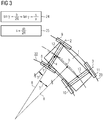
- Fig. 3 shows a running gear of a rail vehicle with a running gear frame 1, a first set of wheels 12 with a first wheel 8, a second wheel 9 and a first axle 2 as well as with a second set of wheels 13 with a third wheel 10, a fourth wheel 11 and a second axle 3 in a curved track.
- a first rail 22 and a second rail 23 are shown.
- a track curve radius R of the track curve, a steering angle ⁇ based on a rotation of the first wheel set 12 about its vertical axis, a center distance b and half a wheel set length a of the first wheel set 12 are shown.
- An adjustment path s for the in Fig. 1 shown pneumatic actuator 19 of the actuator unit 4 is determined.
- the formation formula 24 uses the permissible linearization, according to which, for small angles, the sine function and the tangent function of an angle can be set equal to the angle itself.
- the sine of the steering angle ⁇ is formed as the quotient of half the center distance b and the track curve radius R, the tangent of the steering angle ⁇ from the travel s and half the wheelset length a.
- the term for the sine of the steering angle ⁇ and the term for the tangent of the steering angle ⁇ are equated, ie the steering angle ⁇ is a pure calculation variable and does not have to be measured and processed.
- the travel s is determined as the quotient of the product of half the wheelset length a in the numerator and the center distance b as well as twice the track curve radius R in the denominator.
- the travel s is used in connection with Fig. 2 described method used for the determination of a target actuating force.
Landscapes
- Engineering & Computer Science (AREA)
- Mechanical Engineering (AREA)
- Vehicle Body Suspensions (AREA)
Description
- Die Erfindung bezieht sich auf ein Verfahren zur Achssteuerung von zumindest einer ersten Achse eines Schienenfahrzeugs, wobei die Achssteuerung eine Aktuatoreinheit, ein zu dieser mechanisch wirkungsmäßig parallel geschaltetes, passives Elastiklager und eine Regeleinrichtung aufweist und die Regeleinrichtung zumindest mit der Aktuatoreinheit zwecks Datenübertragung verbunden ist.
- Fahrwerke für Schienenfahrzeuge müssen eine hohe Fahrsicherheit aufweisen. Diese kann beispielsweise durch die Anordnung einer aktiven Achs- bzw. Rad- oder Radsatzsteuerung verbessert werden. Das gezielte Stellen von Achsen bzw. Rädern oder Radsätzen durch aktive Verdrehung derselben um deren Hochachsen dient in bekannter Weise dazu, instabile Fahrzustände zu verhindern.
Ferner wird dadurch der Fahrkomfort durch Vermeidung störender Schwingungen in einem Schienenfahrzeug erhöht.
Dem Rad-Schiene-Kontakt kommt eine besondere, sicherheitsrelevante Bedeutung zu. Unregelmäßigkeiten des Rad-Schiene-Kontakts, z.B. aufgrund der Beschädigung eines Rades, können zu erheblichen Folgeschäden bis hin zu Entgleisungen führen. Auch leichte Beschädigungen, wie z.B. feine Risse können große Schwierigkeiten verursachen, da sie Instandhaltungsarbeiten erforderlich machen, die hohe Kosten und eine eingeschränkte Verfügbarkeit der Schienenfahrzeuge bewirken können.
Durch den Einsatz einer aktiven Achs- bzw. Rad- oder Radsatzsteuerung wird eine Verminderung des Verschleißes bzw. der Rollkontaktermüdung (Rolling Contact Fatigue, RCF) und somit von Unregelmäßigkeiten des Rad-Schiene-Kontakts bei Rädern und Schienen erzielt.
Nach dem Stand der Technik beschreibt beispielsweise dieEP 0 870 664 B1 ein Verfahren zur Radsatzführung von Schienenfahrzeugen. Beispielhaft wird unter anderem eine Einrichtung gezeigt, bei welcher eine Zweikammer-Fluidbuchse zwischen einem Schwingarm und einem Fahrwerksrahmen angeordnet ist, die eine Relativbewegung zwischen dem Schwingarm und dem Fahrwerksrahmen erzeugt und dadurch einen Radsatz-Stellwinkel einstellt.
Als Steuergröße für den Radsatz-Stellwinkel werden ein Ausdrehwinkel zwischen dem Fahrwerksrahmen und einem Wagenkasten oder ein Ausdrehwinkel zwischen zwei Radsätzen und dem Wagenkasten verwendet.
Der genannte Ansatz weist in seiner bekannten Form den Nachteil auf, dass Mess- und Auswerteeinheiten im Zusammenhang mit der Verarbeitung der genannten Ausdrehwinkel, d.h. z.B. Winkelgeber, vorgesehen sein müssen. - In der
EP 2 371 656 A1 wird ein Schienenfahrzeug mit variabler Achsgeometrie vorgestellt. Eine horizontale Winkellage jeder Achse eines Fahrwerks wird während des Betriebs des Schienenfahrzeugs kontinuierlich so eingestellt, dass eine vorgegebene Querverschiebung der Achsen gegeneinander und ein vorgegebener Winkel zwischen den Achsen erzielt wird.
Der genannte Ansatz weist in seiner bekannten Form den Nachteil auf, dass für eine Ansteuerung von exakten Winkeln aufwendige Winkel- oder Wegmessungen erforderlich sind. - Die
DE 198 61 086 B4 zeigt ein Verfahren für eine lenkende Ausrichtung von drehbar an einem Fahrwerk befestigten Rädern eines Schienenfahrzeugs in einem Gleis, wobei ein Soll-Lenkwinkel der Räder in Abhängigkeit von einer Krümmung des Gleises bestimmt wird.
Der genannte Ansatz weist in seiner bekannten Form den Nachteil auf, dass das Verfahren als Lenkwinkelregelung ausgeführt ist, die, für eine Überprüfung auf Erreichung bzw. Einhaltung eines Soll-Lenkwinkels Sensoren für die Winkelerfassung, z.B. Winkelgeber, erfordert. Eine Regelung bezüglich einer Rad-Stellkraft ist in dieser Schrift nicht offenbart.
Weiterhin zeigt dieWO 2016/008731 A1 ein Fahrwerk für ein Schienenfahrzeug mit einer unter Einsatz von Dreieckslenkern ausgebildeten Radsatzführung. Die Dreieckslenker weisen Hydraulikbuchsen auf, mit welchen Fahrwerks-Längssteifigkeiten gesteuert werden. Zur Steuerung dieser Längssteifigkeiten werden mittels einer Einstelleinrichtung hydraulische Drücke der Hydraulikbuchsen auf Grundlage einer Messung von Radsatzbeschleunigungen eingestellt.
DieDE 10 2006 025773 A1 zeigt ein Verfahren zur Regelung eines aktiven Fahrwerks eines Schienenfahrzeugs, für das Aktuatoren vorgesehen sind, welche durch Einstellen von Lenkwinkeln von Radsätzen fahrdynamische Effekte kompensieren. Dazu werden mittels Sensoren Lenkwinkel und für Lasten an den Aktuatoren repräsentative Größen erfasst. - Ferner ist die
EP 0 600 172 A1 bekannt, in welcher ein Drehgestell mit Radsätzen beschrieben ist. Auf den Radsätzen sind kraft- oder weggeregelte Stellglieder angeordnet, die auf Radsatzlager wirken, um ein kontrolliertes Ausdrehen der Radsätze zu gewährleisten.
Die Stellglieder werden auf Grundlage von Abstandsmessungen gesteuert. Aus von einem Sensor gemessenen Abständen werden Ausdrehwinkel zwischen einem Drehgestellrahmen und einem Fahrzeugrahmen ermittelt. Aus diesen Ausdrehwinkeln werden Sollwertvorgaben für die Stellglieder gebildet.
Der Erfindung liegt daher die Aufgabe zugrunde, ein gegenüber dem Stand der Technik verbessertes Verfahren anzugeben. - Erfindungsgemäß wird diese Aufgabe einem Verfahren gemäß Anspruch 1 gelöst.
- Durch einen Verzicht auf Sensoren für die Weg- bzw. Lenkwinkelbestimmung werden die Zahl der Komponenten einer Achs- bzw. Rad- oder Radsatzsteuerung gesenkt und somit deren Bauraumbedarf sowie die Kosten gemindert.
Weiterhin werden dadurch die Robustheit und somit die Verfügbarkeit der Achs- bzw. Rad- oder Radsatzsteuerung erhöht.
Nachfolgend wird die Erfindung anhand von Ausführungsbeispielen näher erläutert.
Es zeigen beispielhaft: - Fig. 1:
- Eine Seitenansicht einer beispielhaften Ausführung eines Fahrwerks, wobei ein Ausschnitt eines Fahrwerksrahmens, ein Rad sowie ein Schwingarm dargestellt sind und, zwischen dem Fahrwerksrahmen und dem Schwingarm angeordnet, eine Aktuatoreinheit sowie ein Elastiklager gezeigt werden,
- Fig. 2:
- Ein Funktionsschaubild zu einer beispielhaften Variante eines erfindungsgemäßen Verfahrens mit einer Aktuatoreinheit, einem Elastiklager, einer Regeleinrichtung, einem Drehratensensor und einem Translationsgeschwindigkeitssensor, und
- Fig. 3:
- Ein Fahrwerk eines Schienenfahrzeuges mit einem ersten Radsatz mit einer ersten Achse und einem zweiten Radsatz mit einer zweiten Achse in einem Gleisbogen, wobei Abhängigkeiten eines Lenkwinkels von Parametern des Fahrwerks und dessen Bewegungszustands sowie von Parametern des Gleisbogens angegeben sind.
- Ein in
Fig. 1 in Seitenansicht dargestellter Ausschnitt einer beispielhaften Variante eines Fahrwerks umfasst einen Ausschnitt eines Fahrwerksrahmens 1 sowie auf einer ersten Schiene 22 ein erstes Rad 8, dessen Mittelpunkt auf einer ersten Achse 2 angeordnet ist.
Das erste Rad 8 ist über eine nicht gezeigte mechanische Kopplung mit einem nicht dargestellten zweiten Rad 9 verbunden, dessen Mittelpunkt ebenfalls auf der ersten Achse 2 angeordnet ist und das auf einer nicht gezeigten zweiten Schiene 23 aufliegt.
Weiterhin werden ein Radlager 14, ein Schwingarm 15 und ein Radlagergehäuse 16 gezeigt.
Zwischen dem Fahrwerksrahmen 1 und dem Schwingarm 15 ist für die Erzeugung einer dynamischen Steifigkeit ein als hydraulische Buchse ausgeführtes, passives Elastiklager 5 mit frequenz- und amplitudenabhängiger statischer und erhöhter dynamischer Steifigkeit vorgesehen.
Die hydraulische Buchse weist eine stabilisierende, federnde und dämpfende Wirkung vornehmlich in der Ebene ihrer Grundfläche auf, d.h. die Steifigkeit wirkt in Richtung einer Fahrwerkslängsache 17 sowie in Richtung einer Fahrwerkshochachse 18.
Eine Aktuatoreinheit 4 ist dem Elastiklager 5 bezüglich der mechanischen Wirkungsweise parallel geschaltet. Sie ist hinsichtlich ihrer Lage in einer Weise angeordnet, dass sie eine Ist-Stellkraft 7 erzeugt, die parallel bezüglich der Richtung der Fahrwerkslängsachse 17 wirkt und über die genannte mechanische Kopplung mit dem zweiten Rad 9 eine Verdrehung des ersten Rades 8 um die Fahrwerkshochachse 18 bzw. um eine zu dieser parallelen Drehachse bewirkt.
Die Aktuatoreinheit 4 weist in dieser beispielhaften Ausführungsvariante einen pneumatischen Aktuator 19 auf, der über nicht dargestellte Aggregate, Leitungen und Ventile mit Druckluft versorgt wird und eine definierte, steuer- bzw. regelbare Ist-Stellkraft 7 erzeugt.
Fig. 2 stellt eine beispielhafte Variante eines erfindungsgemäßen Verfahrens dar. Es werden funktionale Zusammenhänge zwischen einer Aktuatoreinheit 4, einem Elastiklager 5, einer Regeleinrichtung 6, einem Drehratensensor 20 und einem Translationsgeschwindigkeitssensor 21 gezeigt.
Die Aktuatoreinheit 4 erzeugt über einen inFig. 2 nicht dargestellten pneumatischen Aktuator 19 eine Ist-Stellkraft 7 für die Einstellung von Lenkwinkeln γ für eine Achs- bzw. Rad- oder Radsatzsteuerung.
Das Elastiklager 5 weist eine Steifigkeitscharakteristik c auf, die mathematisch einer nichtlinearen Funktion entspricht.
Über den Drehratensensor 20 wird eine Giergeschwindigkeit ω eines Fahrwerks gemessen. Sein Einsatz stellt eine vorteilhafte Lösung für die Bestimmung von - Gleisbogengeometrien dar. Erfindungsgemäß sind jedoch auch andere Mittel vorstellbar, wie z.B. Ortungssysteme, Kreiselsensoren oder Beschleunigungssensoren.
Über den Translationsgeschwindigkeitssensor 21 wird eine Translationsgeschwindigkeit v des Fahrwerks gemessen. Deren Erfassung kann jedoch auch über andere Mittel erfolgen, z.B. über ein Multifunction Vehicle Bus - System (MVB), aus dem entsprechende Daten ausgelesen werden können.
Die Regeleinrichtung 6 umfasst nicht dargestellte Softwaremodule für die Implementierung von Regelungsalgorithmen.
Die Aktuatoreinheit 4, das Elastiklager 5, der Drehratensensor 20 und der Translationsgeschwindigkeitssensor 21 weisen Datenschnittstellen zu der Regeleinrichtung 6 sowie nicht dargestellte Einrichtungen für die Aufbereitung der über die genannten Datenschnittstellen zu übertragenden Informationen auf. - Die Regeleinrichtung 6 empfängt in einer Frequenz von größer oder gleich 10 Hz Informationen über die Ist-Stellkraft 7 bzw. entsprechende Ist-Stellkraftdaten DFIst von der Aktuatoreinheit 4, Informationen über die Steifigkeitscharakteristik c bzw. entsprechende Steifigkeitsdaten Dc von dem Elastiklager 5, Informationen über die Giergeschwindigkeit ω bzw. entsprechende Giergeschwindigkeitsdaten Dω von dem Drehratensensor 20 sowie Informationen über die Translationsgeschwindigkeit v bzw. entsprechende Translationsgeschwindigkeitsdaten Dv von dem Translationsgeschwindigkeitssensor 21.
Bei genanntem Transfer von Steifigkeitsdaten Dc handelt es sich um eine besonders vorteilhafte Lösung. Erfindungsgemäß ist bei Lagern mit bekanntem Steifigkeitsverhalten jedoch auch eine Implementierung von Steifigkeitsverläufen in die Softwaremodule der Regeleinrichtung 6 und somit ein Verzicht auf Datenschnittstellen und Einrichtungen für die Aufbereitung der zu übertragenden Informationen vorstellbar. - In den Softwaremodulen der Regeleinrichtung 6 werden aus den empfangenen Ist-Stellkraftdaten DFIst, den Steifigkeitsdaten Dc, den Giergeschwindigkeitsdaten Dω und den Translationsgeschwindigkeitsdaten Dv Soll-Stellkraftdaten DFSoll gebildet.
Dabei wird aus den Giergeschwindigkeitsdaten Dω bzw. einer Giergeschwindigkeit ω sowie aus den
Translationsgeschwindigkeitsdaten Dv bzw. der Translationsgeschwindigkeit v über die bekannte Vorschrift, wonach sich ein Krümmungskreisradius als Quotient einer Translationsgeschwindigkeit v und einer Giergeschwindigkeit ω ergibt, zunächst ein Gleisbogenradius R bestimmt. - Mittels des Gleisbogenradius R sowie einer in
Fig. 3 dargestellten halben Radsatzlänge a und eines ebendort gezeigten Achsabstands b wird ein Stellweg s für den inFig. 1 gezeigten pneumatischen Aktuator 19 der Aktuatoreinheit 4 gebildet. Die entsprechenden Zusammenhänge sind inFig. 3 dargestellt. Entsprechende Werte für die halbe Radsatzlänge a und den Achsabstand b sind in den Softwaremodulen der Regeleinrichtung 6 implementiert.
Über die bekannte Vorschrift, wonach sich eine Kraft aus dem Produkt einer Steifigkeit und eines Weges ergibt, wird aus den Steifigkeitsdaten Dc bzw. der Steifigkeitscharakteristik c des Elastiklagers 5 und dem Stellweg s eine Soll-Stellkraft gebildet bzw. Soll-Stellkraftdaten DFSoll für die Aktuatoreinheit 4 erzeugt. Die Soll-Stellkraft ist jene Kraft, die für die Überwindung der Steifigkeit des Elastiklagers 5 und für die Erzeugung des Stellwegs s des pneumatischen Aktuators 19 der Aktuatoreinheit 4 erforderlich ist.
Entsprechend einem Abgleich der gebildeten Soll-Stellkraft und der momentan wirkenden Ist-Stellkraft 7 wird der inFig. 1 dargestellte pneumatische Aktuator 19 angesteuert. Hierzu umfasst die Aktuatoreinheit 4 nicht dargestellte Einrichtungen.
Über den bekannten Zusammenhang zwischen einer Kraft, einer Kolbenfläche und einem Druck wird in dem pneumatischen Aktuator 19 ein Druck erzeugt, der die Soll-Stellkraft erzeugt. Ist die Soll-Stellkraft erreicht und wird gehalten, wird sie formal zur Ist-Stellkraft 7, mit der im darauffolgenden Regelungszyklus gegebenenfalls eine neue Soll-Stellkraft abgeglichen wird. - Das Verfahren für die Bestimmung der Soll-Stellkraft, die Ansteuerung der Aktuatoreinheit 4 für die Erzeugung der Soll-Stellkraft sowie die Aufbereitung und Übertragung der Ist-Stellkraftdaten DFIst, der Soll-Stellkraftdaten DFSoll, der Steifigkeitsdaten Dc, der Giergeschwindigkeitsdaten Dω sowie der Translationsgeschwindigkeitsdaten Dv erfolgen zyklisch mit einer Frequenz von größer oder gleich 10 Hz.
-
Fig. 3 zeigt ein Fahrwerk eines Schienenfahrzeuges mit einem Fahrwerksrahmen 1, einem ersten Radsatz 12 mit einem ersten Rad 8, einem zweiten Rad 9 und einer ersten Achse 2 sowie mit einem zweiten Radsatz 13 mit einem dritten Rad 10, einem vierten Rad 11 und einer zweiten Achse 3 in einem Gleisbogen. Es sind eine erste Schiene 22 und eine zweite Schiene 23 dargestellt.
Weiterhin sind ein Gleisbogenradius R des Gleisbogens, ein Lenkwinkel γ bezogen auf eine Verdrehung des ersten Radsatzes 12 um seine Hochachse, ein Achsabstand b und eine halbe Radsatzlänge a des ersten Radsatzes 12 dargestellt.
Über eine Bildungsformel 24 wird durch Umformung in einen Ergebnisterm 25 ein Stellweg s für den inFig. 1 gezeigten pneumatischen Aktuator 19 der Aktuatoreinheit 4 bestimmt.
Die Bildungsformel 24 verwendet die zulässige Linearisierung, wonach bei kleinen Winkeln die Sinusfunktion und die Tangensfunktion eines Winkels gleich dem Winkel selbst gesetzt werden können.
Der Sinus des Lenkwinkels γ wird als Quotient aus der Hälfte des Achsabstands b und dem Gleisbogenradius R gebildet, der Tangens des Lenkwinkels γ aus dem Stellweg s und der halben Radsatzlänge a.
Unter Berücksichtigung der genannten Linearisierung werden der Term für den Sinus des Lenkwinkels γ und der Term für den Tangens des Lenkwinkels γ gleichgesetzt, d.h. der Lenkwinkel γ ist eine reine Rechengröße und muss nicht gemessen und verarbeitet werden.
Über einen Umformung in den Ergebnisterm 25 wird der Stellweg s als Quotient aus dem im Zähler stehenden Produkt der halben Radsatzlänge a und dem Achsabstand b sowie dem im Nenner stehenden Zweifachen des Gleisbogenradius R bestimmt.
Der Stellweg s wird in dem im Zusammenhang mitFig. 2 beschriebenen Verfahren für die Bestimmung einer Soll-Stellkraft verwendet. -
- 1
- Fahrwerksrahmen
- 2
- Erste Achse
- 3
- Zweite Achse
- 4
- Aktuatoreinheit
- 5
- Elastiklager
- 6
- Regeleinrichtung
- 7
- Ist-Stellkraft
- 8
- Erstes Rad
- 9
- Zweites Rad
- 10
- Drittes Rad
- 11
- Viertes Rad
- 12
- Erster Radsatz
- 13
- Zweiter Radsatz
- 14
- Radlager
- 15
- Schwingarm
- 16
- Radlagergehäuse
- 17
- Fahrwerkslängsachse
- 18
- Fahrwerkshochachse
- 19
- Pneumatischer Aktuator
- 20
- Drehratensensor
- 21
- Translationsgeschwindigkeitssensor
- 22
- Erste Schiene
- 23
- Zweite Schiene
- 24
- Bildungsformel
- 25
- Ergebnisterm
- γ
- Lenkwinkel
- c
- Steifigkeitscharakteristik
- v
- Translationsgeschwindigkeit
- ω
- Giergeschwindigkeit
- R
- Gleisbogenradius
- b
- Achsabstand
- a
- Halbe Radsatzlänge
- s
- Stellweg
- Dc
- Steifigkeitsdaten
- Dω
- Giergeschwindigkeitsdaten
- Dv
- Translationsgeschwindigkeitsdaten
- DFIst
- Ist-Stellkraftdaten
- DFSoll
- Soll-Stellkraftdaten
Claims (13)
- Verfahren zur Achssteuerung von zumindest einer ersten Achse eines Schienenfahrzeugs, wobei die Achssteuerung eine Aktuatoreinheit, ein zu dieser mechanisch wirkungsmäßig parallel geschaltetes, passives Elastiklager und eine Regeleinrichtung aufweist und die Regeleinrichtung zumindest mit der Aktuatoreinheit zwecks Datenübertragung verbunden ist, wobei von der Regeleinrichtung (6) als Steuer- bzw. Regelgröße für Lenkwinkel γ der ersten Achse des Schienenfahrzeugs ausschließlich eine Ist-Stellkraft (7) der Aktuatoreinheit (4) eingesetzt wird.
- Verfahren nach Anspruch 1, dadurch gekennzeichnet, dass die Ist-Stellkraft (7) aus Informationen über zumindest eine bekannte Eigenschaft des Schienenfahrzeugs, insbesondere über eine Steifigkeitscharakteristik c des Elastiklagers (5), sowie aus Informationen über eine Gleisgeometrie gebildet wird.
- Verfahren nach Anspruch 1, dadurch gekennzeichnet, dass die Ist-Stellkraft (7) aus Informationen über zumindest eine bekannte Eigenschaft des Schienenfahrzeugs, insbesondere über eine Steifigkeitscharakteristik c des Elastiklagers (5), sowie aus Informationen über Bewegungszustände des Schienenfahrzeugs, insbesondere über eine Translationsgeschwindigkeit v, gebildet wird.
- Verfahren nach Anspruch 2 oder 3, dadurch gekennzeichnet, dass als bekannte Eigenschaft des Schienenfahrzeugs die Steifigkeitscharakteristik c des Elastiklagers (5) eingesetzt wird.
- Verfahren nach Anspruch 1, dadurch gekennzeichnet, dass Lenkwinkel γ zumindest eines ersten Losradsatzes eingestellt werden.
- Verfahren nach Anspruch 1, dadurch gekennzeichnet, dass Lenkwinkel γ zumindest eines ersten Radsatzes (12) eingestellt werden.
- Verfahren nach Anspruch 2 oder 3, dadurch gekennzeichnet, dass die Bildung von Informationen mittels zumindest eines Translationsgeschwindigkeitssensors (21) erfolgt.
- Verfahren nach Anspruch 2 oder 3, dadurch gekennzeichnet, dass die Bildung von Informationen mittels zumindest eines Ortungssystems erfolgt.
- Verfahren nach Anspruch 7, dadurch gekennzeichnet, dass die Bildung von Informationen mittels zumindest eines Drehratensensors (20) erfolgt.
- Verfahren nach Anspruch 7, dadurch gekennzeichnet, dass die Bildung von Informationen mittels zumindest eines Kreiselsensors erfolgt.
- Verfahren nach Anspruch 1, dadurch gekennzeichnet, dass ein Gleisbogenradius R als Quotient einer Translationsgeschwindigkeit v und einer Giergeschwindigkeit ω zumindest eines Fahrwerks des Schienenfahrzeugs bestimmt wird.
- Verfahren nach Anspruch 11, dadurch gekennzeichnet, dass mittels des Gleisbogenradius R sowie einer halben Radsatzlänge a und eines Achsabstands b des zumindest einen Fahrwerks ein Stellweg s für die Aktuatoreinheit (4) gebildet wird.
- Verfahren nach Anspruch 12, dadurch gekennzeichnet, dass mit der Steifigkeitscharakteristik c des Elastiklagers (5) und dem Stellweg s für die Aktuatoreinheit (4) eine Soll-Stellkraft zur Steuerung bzw. Regelung der Ist-Stellkraft (7) gebildet wird.
Priority Applications (1)
| Application Number | Priority Date | Filing Date | Title |
|---|---|---|---|
| PL17164999T PL3239015T3 (pl) | 2016-04-28 | 2017-04-05 | Prowadzenie pojazdu wzdłuż zadanego toru z regulowaną siłą dla pojazdu szynowego |
Applications Claiming Priority (1)
| Application Number | Priority Date | Filing Date | Title |
|---|---|---|---|
| ATA50377/2016A AT518698B1 (de) | 2016-04-28 | 2016-04-28 | Kraftgeregelte Spurführung für ein Schienenfahrzeug |
Publications (2)
| Publication Number | Publication Date |
|---|---|
| EP3239015A1 EP3239015A1 (de) | 2017-11-01 |
| EP3239015B1 true EP3239015B1 (de) | 2021-05-26 |
Family
ID=58536741
Family Applications (1)
| Application Number | Title | Priority Date | Filing Date |
|---|---|---|---|
| EP17164999.9A Active EP3239015B1 (de) | 2016-04-28 | 2017-04-05 | Kraftgeregelte spurführung für ein schienenfahrzeug |
Country Status (4)
| Country | Link |
|---|---|
| EP (1) | EP3239015B1 (de) |
| AT (1) | AT518698B1 (de) |
| ES (1) | ES2875525T3 (de) |
| PL (1) | PL3239015T3 (de) |
Families Citing this family (3)
| Publication number | Priority date | Publication date | Assignee | Title |
|---|---|---|---|---|
| DE102017114421A1 (de) * | 2017-06-28 | 2019-01-03 | Rheinisch-Westfälische Technische Hochschule (Rwth) Aachen | Gelenktes Losradpaar für Schienenfahrzeuge |
| PT110903B (pt) * | 2018-08-03 | 2021-08-02 | Inst Superior Tecnico | Dispositivo de guiamento ferroviário e o seu método de operar. |
| DE102020123592A1 (de) | 2020-09-10 | 2022-03-10 | Liebherr-Transportation Systems Gmbh & Co Kg | Aktive Radsatzsteuerung für ein Schienenfahrzeug |
Family Cites Families (5)
| Publication number | Priority date | Publication date | Assignee | Title |
|---|---|---|---|---|
| DE4240098A1 (de) * | 1992-11-28 | 1994-06-01 | Krupp Verkehrstechnik Gmbh | Fahrwerk für Schienenfahrzeuge |
| AT407140B (de) * | 1993-11-26 | 2000-12-27 | Integral Verkehrstechnik Ag | Einrichtung zur steuerung eines rades, insbesondere eines radsatzes eines schienenfahrzeuges |
| DE19861086B4 (de) * | 1998-06-13 | 2004-04-15 | Bombardier Transportation Gmbh | Verfahren zur Achsausrichtung bei Schienenfahrzeugen |
| DE102006025773A1 (de) * | 2006-05-31 | 2007-12-06 | Bombardier Transportation Gmbh | Verfahren zur Regelung eines aktiven Fahrwerks eines Schienenfahrzeugs |
| DE102014214055A1 (de) * | 2014-07-18 | 2016-01-21 | Siemens Aktiengesellschaft | Fahrwerk für ein Schienenfahrzeug |
-
2016
- 2016-04-28 AT ATA50377/2016A patent/AT518698B1/de not_active IP Right Cessation
-
2017
- 2017-04-05 PL PL17164999T patent/PL3239015T3/pl unknown
- 2017-04-05 ES ES17164999T patent/ES2875525T3/es active Active
- 2017-04-05 EP EP17164999.9A patent/EP3239015B1/de active Active
Non-Patent Citations (1)
| Title |
|---|
| None * |
Also Published As
| Publication number | Publication date |
|---|---|
| AT518698A1 (de) | 2017-12-15 |
| PL3239015T3 (pl) | 2021-11-15 |
| AT518698B1 (de) | 2021-06-15 |
| EP3239015A1 (de) | 2017-11-01 |
| ES2875525T3 (es) | 2021-11-10 |
Similar Documents
| Publication | Publication Date | Title |
|---|---|---|
| EP0877694B1 (de) | Verfahren zur beeinflussung des knickwinkels von schienenfahrzeug-wagenkästen und schienenfahrzeug zur durchführung des verfahrens | |
| EP2414207B1 (de) | Fahrzeug mit wankkompensation | |
| DE102013001973B3 (de) | Spurführung eines Schienenfahrzeugs | |
| EP2021223A2 (de) | Verfahren zur regelung eines aktiven fahrwerks eines schienenfahrzeugs | |
| EP0655378B1 (de) | Einrichtung und Verfahren von Radsätzen von Schienenfahrzeugen | |
| EP3239015B1 (de) | Kraftgeregelte spurführung für ein schienenfahrzeug | |
| EP1412240B1 (de) | Verfahren und vorrichtung zur aktiven radialsteuerung von radpaaren oder radsätzen von fahrzeugen | |
| EP0870664B1 (de) | Verfahren und Einrichtung zur Radsatzführung von Schienen-Fahrzeugen | |
| EP1451030B1 (de) | Positionseinstellung eines fahrzeug-wagenkörpers | |
| EP0833766A1 (de) | Schienenfahrzeug mit einem einachsigen laufwerk | |
| EP3544875B1 (de) | Fahrwerk für schienenfahrzeuge | |
| WO2010113045A2 (de) | Fahrzeug mit wankkompensation | |
| EP0736439B1 (de) | Fahrwerk für Schienenfahrzeuge | |
| DE102016226072A1 (de) | Sicherheitsfunktion und Steuergerät zur Überwachung sowie Steuerung von Wankstabilisatoren | |
| DE102016215004B4 (de) | Verfahren zum Betreiben eines elektrischen Stellmotors, Wankstabilisatoreinrichtung und Fahrzeug | |
| EP3934960A1 (de) | Vorrichtung und verfahren zur bestimmung von abständen zwischen wagenkästen und fahrwerken von fahrzeugen | |
| DE2848398B1 (de) | Spurfuehrung eines Radsatzes fuer Schienenfahrzeuge | |
| AT524550B1 (de) | Fahrwerk für ein Schienenfahrzeug | |
| EP1193154A1 (de) | Verfahren und Vorrichtung zur Stabilisierung des Wellenlaufes von Eisenbahnradsätzen | |
| DE102019213272A1 (de) | Verfahren zum Betreiben eines verstellbaren Wankstabilisators | |
| EP4227188B1 (de) | Schienenfahrzeugfahrwerk mit einer vorrichtung zum steuern einer radachse | |
| EP3241716B1 (de) | Fahrwerk für ein schienenfahrzeug | |
| EP2948359B1 (de) | Schienenfahrzeug mit neigetechnik | |
| AT518035B1 (de) | Fahrwerk für ein Schienenfahrzeug | |
| DE102017114421A1 (de) | Gelenktes Losradpaar für Schienenfahrzeuge |
Legal Events
| Date | Code | Title | Description |
|---|---|---|---|
| PUAI | Public reference made under article 153(3) epc to a published international application that has entered the european phase |
Free format text: ORIGINAL CODE: 0009012 |
|
| STAA | Information on the status of an ep patent application or granted ep patent |
Free format text: STATUS: THE APPLICATION HAS BEEN PUBLISHED |
|
| AK | Designated contracting states |
Kind code of ref document: A1 Designated state(s): AL AT BE BG CH CY CZ DE DK EE ES FI FR GB GR HR HU IE IS IT LI LT LU LV MC MK MT NL NO PL PT RO RS SE SI SK SM TR |
|
| AX | Request for extension of the european patent |
Extension state: BA ME |
|
| STAA | Information on the status of an ep patent application or granted ep patent |
Free format text: STATUS: REQUEST FOR EXAMINATION WAS MADE |
|
| 17P | Request for examination filed |
Effective date: 20180430 |
|
| RBV | Designated contracting states (corrected) |
Designated state(s): AL AT BE BG CH CY CZ DE DK EE ES FI FR GB GR HR HU IE IS IT LI LT LU LV MC MK MT NL NO PL PT RO RS SE SI SK SM TR |
|
| RAP1 | Party data changed (applicant data changed or rights of an application transferred) |
Owner name: SIEMENS MOBILITY GMBH |
|
| RAP1 | Party data changed (applicant data changed or rights of an application transferred) |
Owner name: SIEMENS MOBILITY AUSTRIA GMBH |
|
| GRAP | Despatch of communication of intention to grant a patent |
Free format text: ORIGINAL CODE: EPIDOSNIGR1 |
|
| STAA | Information on the status of an ep patent application or granted ep patent |
Free format text: STATUS: GRANT OF PATENT IS INTENDED |
|
| RIC1 | Information provided on ipc code assigned before grant |
Ipc: B61F 5/38 20060101AFI20201030BHEP |
|
| INTG | Intention to grant announced |
Effective date: 20201123 |
|
| GRAS | Grant fee paid |
Free format text: ORIGINAL CODE: EPIDOSNIGR3 |
|
| GRAA | (expected) grant |
Free format text: ORIGINAL CODE: 0009210 |
|
| STAA | Information on the status of an ep patent application or granted ep patent |
Free format text: STATUS: THE PATENT HAS BEEN GRANTED |
|
| AK | Designated contracting states |
Kind code of ref document: B1 Designated state(s): AL AT BE BG CH CY CZ DE DK EE ES FI FR GB GR HR HU IE IS IT LI LT LU LV MC MK MT NL NO PL PT RO RS SE SI SK SM TR |
|
| REG | Reference to a national code |
Ref country code: GB Ref legal event code: FG4D Free format text: NOT ENGLISH |
|
| REG | Reference to a national code |
Ref country code: CH Ref legal event code: EP |
|
| REG | Reference to a national code |
Ref country code: DE Ref legal event code: R096 Ref document number: 502017010442 Country of ref document: DE |
|
| REG | Reference to a national code |
Ref country code: AT Ref legal event code: REF Ref document number: 1395950 Country of ref document: AT Kind code of ref document: T Effective date: 20210615 |
|
| REG | Reference to a national code |
Ref country code: IE Ref legal event code: FG4D Free format text: LANGUAGE OF EP DOCUMENT: GERMAN |
|
| REG | Reference to a national code |
Ref country code: LT Ref legal event code: MG9D |
|
| PG25 | Lapsed in a contracting state [announced via postgrant information from national office to epo] |
Ref country code: HR Free format text: LAPSE BECAUSE OF FAILURE TO SUBMIT A TRANSLATION OF THE DESCRIPTION OR TO PAY THE FEE WITHIN THE PRESCRIBED TIME-LIMIT Effective date: 20210526 Ref country code: BG Free format text: LAPSE BECAUSE OF FAILURE TO SUBMIT A TRANSLATION OF THE DESCRIPTION OR TO PAY THE FEE WITHIN THE PRESCRIBED TIME-LIMIT Effective date: 20210826 Ref country code: FI Free format text: LAPSE BECAUSE OF FAILURE TO SUBMIT A TRANSLATION OF THE DESCRIPTION OR TO PAY THE FEE WITHIN THE PRESCRIBED TIME-LIMIT Effective date: 20210526 Ref country code: LT Free format text: LAPSE BECAUSE OF FAILURE TO SUBMIT A TRANSLATION OF THE DESCRIPTION OR TO PAY THE FEE WITHIN THE PRESCRIBED TIME-LIMIT Effective date: 20210526 |
|
| REG | Reference to a national code |
Ref country code: NL Ref legal event code: MP Effective date: 20210526 |
|
| REG | Reference to a national code |
Ref country code: ES Ref legal event code: FG2A Ref document number: 2875525 Country of ref document: ES Kind code of ref document: T3 Effective date: 20211110 |
|
| PG25 | Lapsed in a contracting state [announced via postgrant information from national office to epo] |
Ref country code: LV Free format text: LAPSE BECAUSE OF FAILURE TO SUBMIT A TRANSLATION OF THE DESCRIPTION OR TO PAY THE FEE WITHIN THE PRESCRIBED TIME-LIMIT Effective date: 20210526 Ref country code: GR Free format text: LAPSE BECAUSE OF FAILURE TO SUBMIT A TRANSLATION OF THE DESCRIPTION OR TO PAY THE FEE WITHIN THE PRESCRIBED TIME-LIMIT Effective date: 20210827 Ref country code: IS Free format text: LAPSE BECAUSE OF FAILURE TO SUBMIT A TRANSLATION OF THE DESCRIPTION OR TO PAY THE FEE WITHIN THE PRESCRIBED TIME-LIMIT Effective date: 20210926 Ref country code: PT Free format text: LAPSE BECAUSE OF FAILURE TO SUBMIT A TRANSLATION OF THE DESCRIPTION OR TO PAY THE FEE WITHIN THE PRESCRIBED TIME-LIMIT Effective date: 20210927 Ref country code: NO Free format text: LAPSE BECAUSE OF FAILURE TO SUBMIT A TRANSLATION OF THE DESCRIPTION OR TO PAY THE FEE WITHIN THE PRESCRIBED TIME-LIMIT Effective date: 20210826 Ref country code: SE Free format text: LAPSE BECAUSE OF FAILURE TO SUBMIT A TRANSLATION OF THE DESCRIPTION OR TO PAY THE FEE WITHIN THE PRESCRIBED TIME-LIMIT Effective date: 20210526 Ref country code: RS Free format text: LAPSE BECAUSE OF FAILURE TO SUBMIT A TRANSLATION OF THE DESCRIPTION OR TO PAY THE FEE WITHIN THE PRESCRIBED TIME-LIMIT Effective date: 20210526 |
|
| PG25 | Lapsed in a contracting state [announced via postgrant information from national office to epo] |
Ref country code: NL Free format text: LAPSE BECAUSE OF FAILURE TO SUBMIT A TRANSLATION OF THE DESCRIPTION OR TO PAY THE FEE WITHIN THE PRESCRIBED TIME-LIMIT Effective date: 20210526 |
|
| PG25 | Lapsed in a contracting state [announced via postgrant information from national office to epo] |
Ref country code: SM Free format text: LAPSE BECAUSE OF FAILURE TO SUBMIT A TRANSLATION OF THE DESCRIPTION OR TO PAY THE FEE WITHIN THE PRESCRIBED TIME-LIMIT Effective date: 20210526 Ref country code: SK Free format text: LAPSE BECAUSE OF FAILURE TO SUBMIT A TRANSLATION OF THE DESCRIPTION OR TO PAY THE FEE WITHIN THE PRESCRIBED TIME-LIMIT Effective date: 20210526 Ref country code: RO Free format text: LAPSE BECAUSE OF FAILURE TO SUBMIT A TRANSLATION OF THE DESCRIPTION OR TO PAY THE FEE WITHIN THE PRESCRIBED TIME-LIMIT Effective date: 20210526 Ref country code: EE Free format text: LAPSE BECAUSE OF FAILURE TO SUBMIT A TRANSLATION OF THE DESCRIPTION OR TO PAY THE FEE WITHIN THE PRESCRIBED TIME-LIMIT Effective date: 20210526 Ref country code: DK Free format text: LAPSE BECAUSE OF FAILURE TO SUBMIT A TRANSLATION OF THE DESCRIPTION OR TO PAY THE FEE WITHIN THE PRESCRIBED TIME-LIMIT Effective date: 20210526 |
|
| REG | Reference to a national code |
Ref country code: DE Ref legal event code: R097 Ref document number: 502017010442 Country of ref document: DE |
|
| PLBE | No opposition filed within time limit |
Free format text: ORIGINAL CODE: 0009261 |
|
| STAA | Information on the status of an ep patent application or granted ep patent |
Free format text: STATUS: NO OPPOSITION FILED WITHIN TIME LIMIT |
|
| 26N | No opposition filed |
Effective date: 20220301 |
|
| PG25 | Lapsed in a contracting state [announced via postgrant information from national office to epo] |
Ref country code: IS Free format text: LAPSE BECAUSE OF FAILURE TO SUBMIT A TRANSLATION OF THE DESCRIPTION OR TO PAY THE FEE WITHIN THE PRESCRIBED TIME-LIMIT Effective date: 20210926 Ref country code: AL Free format text: LAPSE BECAUSE OF FAILURE TO SUBMIT A TRANSLATION OF THE DESCRIPTION OR TO PAY THE FEE WITHIN THE PRESCRIBED TIME-LIMIT Effective date: 20210526 |
|
| PG25 | Lapsed in a contracting state [announced via postgrant information from national office to epo] |
Ref country code: IT Free format text: LAPSE BECAUSE OF FAILURE TO SUBMIT A TRANSLATION OF THE DESCRIPTION OR TO PAY THE FEE WITHIN THE PRESCRIBED TIME-LIMIT Effective date: 20210526 |
|
| REG | Reference to a national code |
Ref country code: BE Ref legal event code: MM Effective date: 20220430 |
|
| PG25 | Lapsed in a contracting state [announced via postgrant information from national office to epo] |
Ref country code: MC Free format text: LAPSE BECAUSE OF FAILURE TO SUBMIT A TRANSLATION OF THE DESCRIPTION OR TO PAY THE FEE WITHIN THE PRESCRIBED TIME-LIMIT Effective date: 20210526 Ref country code: LU Free format text: LAPSE BECAUSE OF NON-PAYMENT OF DUE FEES Effective date: 20220405 |
|
| PG25 | Lapsed in a contracting state [announced via postgrant information from national office to epo] |
Ref country code: BE Free format text: LAPSE BECAUSE OF NON-PAYMENT OF DUE FEES Effective date: 20220430 |
|
| PG25 | Lapsed in a contracting state [announced via postgrant information from national office to epo] |
Ref country code: IE Free format text: LAPSE BECAUSE OF NON-PAYMENT OF DUE FEES Effective date: 20220405 |
|
| PG25 | Lapsed in a contracting state [announced via postgrant information from national office to epo] |
Ref country code: HU Free format text: LAPSE BECAUSE OF FAILURE TO SUBMIT A TRANSLATION OF THE DESCRIPTION OR TO PAY THE FEE WITHIN THE PRESCRIBED TIME-LIMIT; INVALID AB INITIO Effective date: 20170405 |
|
| PG25 | Lapsed in a contracting state [announced via postgrant information from national office to epo] |
Ref country code: MK Free format text: LAPSE BECAUSE OF FAILURE TO SUBMIT A TRANSLATION OF THE DESCRIPTION OR TO PAY THE FEE WITHIN THE PRESCRIBED TIME-LIMIT Effective date: 20210526 Ref country code: CY Free format text: LAPSE BECAUSE OF FAILURE TO SUBMIT A TRANSLATION OF THE DESCRIPTION OR TO PAY THE FEE WITHIN THE PRESCRIBED TIME-LIMIT Effective date: 20210526 |
|
| PG25 | Lapsed in a contracting state [announced via postgrant information from national office to epo] |
Ref country code: TR Free format text: LAPSE BECAUSE OF FAILURE TO SUBMIT A TRANSLATION OF THE DESCRIPTION OR TO PAY THE FEE WITHIN THE PRESCRIBED TIME-LIMIT Effective date: 20210526 |
|
| PG25 | Lapsed in a contracting state [announced via postgrant information from national office to epo] |
Ref country code: MT Free format text: LAPSE BECAUSE OF FAILURE TO SUBMIT A TRANSLATION OF THE DESCRIPTION OR TO PAY THE FEE WITHIN THE PRESCRIBED TIME-LIMIT Effective date: 20210526 |
|
| PGFP | Annual fee paid to national office [announced via postgrant information from national office to epo] |
Ref country code: PL Payment date: 20250327 Year of fee payment: 9 |
|
| PGFP | Annual fee paid to national office [announced via postgrant information from national office to epo] |
Ref country code: DE Payment date: 20250620 Year of fee payment: 9 |
|
| PGFP | Annual fee paid to national office [announced via postgrant information from national office to epo] |
Ref country code: GB Payment date: 20250507 Year of fee payment: 9 |
|
| PGFP | Annual fee paid to national office [announced via postgrant information from national office to epo] |
Ref country code: FR Payment date: 20250411 Year of fee payment: 9 |
|
| PGFP | Annual fee paid to national office [announced via postgrant information from national office to epo] |
Ref country code: AT Payment date: 20250307 Year of fee payment: 9 |
|
| PGFP | Annual fee paid to national office [announced via postgrant information from national office to epo] |
Ref country code: CZ Payment date: 20250401 Year of fee payment: 9 |
|
| PGFP | Annual fee paid to national office [announced via postgrant information from national office to epo] |
Ref country code: ES Payment date: 20250721 Year of fee payment: 9 |
|
| PGFP | Annual fee paid to national office [announced via postgrant information from national office to epo] |
Ref country code: CH Payment date: 20250709 Year of fee payment: 9 |