EP3238857A1 - Zweistoff-sekundärkühlung für eine stranggiessanlage - Google Patents
Zweistoff-sekundärkühlung für eine stranggiessanlage Download PDFInfo
- Publication number
- EP3238857A1 EP3238857A1 EP17164822.3A EP17164822A EP3238857A1 EP 3238857 A1 EP3238857 A1 EP 3238857A1 EP 17164822 A EP17164822 A EP 17164822A EP 3238857 A1 EP3238857 A1 EP 3238857A1
- Authority
- EP
- European Patent Office
- Prior art keywords
- gas
- coolant
- compressor
- nozzle
- continuous casting
- Prior art date
- Legal status (The legal status is an assumption and is not a legal conclusion. Google has not performed a legal analysis and makes no representation as to the accuracy of the status listed.)
- Granted
Links
Images

Classifications
-
- B—PERFORMING OPERATIONS; TRANSPORTING
- B22—CASTING; POWDER METALLURGY
- B22D—CASTING OF METALS; CASTING OF OTHER SUBSTANCES BY THE SAME PROCESSES OR DEVICES
- B22D11/00—Continuous casting of metals, i.e. casting in indefinite lengths
- B22D11/12—Accessories for subsequent treating or working cast stock in situ
- B22D11/124—Accessories for subsequent treating or working cast stock in situ for cooling
-
- B—PERFORMING OPERATIONS; TRANSPORTING
- B22—CASTING; POWDER METALLURGY
- B22D—CASTING OF METALS; CASTING OF OTHER SUBSTANCES BY THE SAME PROCESSES OR DEVICES
- B22D11/00—Continuous casting of metals, i.e. casting in indefinite lengths
- B22D11/12—Accessories for subsequent treating or working cast stock in situ
- B22D11/124—Accessories for subsequent treating or working cast stock in situ for cooling
- B22D11/1246—Nozzles; Spray heads
-
- B—PERFORMING OPERATIONS; TRANSPORTING
- B22—CASTING; POWDER METALLURGY
- B22D—CASTING OF METALS; CASTING OF OTHER SUBSTANCES BY THE SAME PROCESSES OR DEVICES
- B22D11/00—Continuous casting of metals, i.e. casting in indefinite lengths
- B22D11/16—Controlling or regulating processes or operations
- B22D11/22—Controlling or regulating processes or operations for cooling cast stock or mould
- B22D11/225—Controlling or regulating processes or operations for cooling cast stock or mould for secondary cooling
Definitions
- the invention relates to a device and a method for multi-material secondary cooling in a continuous casting plant, wherein a multi-substance coolant, preferably an air / water mixture, is applied in a secondary cooling zone on surfaces of the cast strand.
- a multi-substance coolant preferably an air / water mixture
- a cooling medium which is for example water or a mixture of air and water, is applied or sprayed onto the metal surfaces of the slab to be cooled.
- the slab or cast strand is deprived of heat by evaporation and / or heating of the cooling medium.
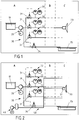
- the FIG. 1 shows a schematic of a conventional water-secondary cooling for a continuous casting plant.
- a pump 20 which may be a simple or frequency-controlled water pump, placed in a water distribution network 30.
- the control valves 31 may be equipped with a valve control and / or a volumetric flow meter, together with the reference numeral 32, to regulate and measure the volume flow via a piping to the nozzle 33.
- the continuous casting plant may have one or more so-called overflow control valves 34, which have an excess amount of water between the water pump 20 and branch off the control valves 31 and lead into a sintering trough 35.
- the reference numeral A denotes a fixed part of the installation, a media room or distribution room
- the reference numeral C denotes a continuous casting segment in the vicinity of the cast strand in which the nozzles 33 for dispensing coolant
- the reference symbol B denotes a section, in which a piping as part of the water distribution network 30, the water from the distribution chamber A to the continuous casting C feeds.
- a conventional water nozzle 33 of simple construction has a fixed orifice for discharging the water. This leads to an invariant pressure / volume flow characteristic, in which each pressure, for example in the pressure range of 0.5 to 12 bar, exactly one water flow point is assigned.
- the desired water volume flow is adjusted with the aforementioned control valve 31 (also referred to as a volume flow control valve) in the distributor room.
- the single-fluid nozzles 33 have a relatively small adjustment range of approximately 1: 3.2 with respect to water flow.
- the water-secondary cooling system is not very flexible in this sense. Furthermore, the regulation or change of the volume flow can lead to an energy loss.
- control valves 31 are designed, for example, as piston valves
- a large amount of energy of the water flow at the ring diffuser of the piston valve is converted into friction, in particular at low water consumption.
- Conventional flat jet or full cone spray pattern nozzles are subdivided along standardized volume flow and jet angle graduations and assigned to the secondary carpet zone nozzle carpet according to a system design tradeoff.
- Another disadvantage of the system described concerns the maintenance required to remove residues on the nozzles, especially lime deposits. Such deposits occur especially at low water flow rates. The small cross-sections of the nozzles set quickly.
- a further development of the water cooling described above is the secondary cooling as two-fluid cooling by means of an air / water mixture perform.
- water is premixed in a mixing chamber with air, and the mixture is fed to one or more nozzles and output as atomized binary mixture.
- Such a two-fluid cooling is for example in the DE 100 15 832 A1 described.
- FIG. 2 shows a schematic of a conventional dual-fluid secondary cooling for a continuous casting plant.
- air is compressed by means of a power driven compressor 40 and directed to one or more mixing chambers 51 in an air distribution network 50, which is largely separate from the water distribution network 30. There, the two distribution networks come together, water and air are mixed in the mixing chambers 51 and output from the nozzles 33.
- the air in the dual-fluid secondary cooling is used for water jet atomization and at the same time for adjusting and maintaining the opening angle of the cooling jet at the nozzle 33, at different pressure settings, in particular at a low water pressure.
- the strand or slab surface is sprayed with an aerosol of very fine water droplets.
- the adjustment range with regard to the amount of water can thus be extended to about 1:14.
- the disadvantage is a poor energy efficiency and consequent high investment and operating costs for the implementation of the dual-material secondary cooling, resulting in particular from the electricity and energy costs for the air compression by means of the compressor 40.
- the EP 2 527 061 A1 describes a technical variant of the single-fluid secondary cooling, are used in the switching valves for intermittent opening and closing of the flow rate of a coolant.
- the volume flow control takes place with the help of a pulse width modulation.
- the use of solenoid valves and Other electronic components require a high level of maintenance and servicing, especially when used in the harsh conditions of continuous casting.
- the cooling effect cyclic and can lead to increased thermal stresses, which in turn can have an increased cracking in the cast product.
- An object of the invention is to provide a device and a method for multi-material secondary cooling for a continuous casting, which overcome at least one of the above-mentioned technical disadvantages.
- the device and method should be energy efficient and flexible, i. ensure a large adjustment range of the volume flow and / or other parameters, and enable a safe and durable spray pattern.
- the device according to the invention is used for multi-material secondary cooling, in particular two-component secondary cooling, for one, preferably in a continuous casting plant.
- the apparatus has at least one nozzle for dispensing a multi-fluid coolant onto surfaces of the cast strand.
- a "cast strand" is here any cast or found casting, for example, a slab, referred to, which is subjected to a secondary cooling. In particular, it does not depend on the shape or the concrete composition of the cast product or on its processing stage, as far as it has left the casting mold.
- the multi-fluid coolant has at least two components, a liquid coolant and a gas.
- the liquid coolant has water or is water, and preferably the gas has air or is air.
- the air can be used for water atomization and preferably for Modeling and / or maintaining the opening angle of the cooling jet can be used or shared.
- the liquid coolant and the gas are mixed in at least one mixing chamber, which is part of the nozzle or fluidly connected to the nozzle, to the multi-fluid coolant.
- the apparatus further comprises a coolant distribution network, with at least one coolant line for transporting the liquid coolant to the mixing chamber and at least one control valve for controlling the volume flow of the liquid coolant to be supplied to the mixing chamber.
- the device has a gas distribution network with at least one gas line for transporting the gas to the mixing chamber.
- coolant distribution network and "gas distribution network” each designate an arrangement of fluidic devices, such as lines, pipes, valves, branches, etc., which need not be arranged net like a net yet several different or a plurality of said devices must have.
- the coolant distribution network has one or more control valves for controlling the volume flow of the liquid coolant and that the two distribution networks communicate with one another at one or more mixing chambers in terms of flow.
- the coolant distribution network has a control valve and a pipe
- the gas distribution network has a pipe.
- the apparatus further comprises a refrigerant driven compressor having a turbine and a gas compressor.
- the turbine and the gas compressor are connected to each other, preferably mechanically.
- the compressor is configured to rotate the turbine of a portion of the liquid coolant, whereby the gas compressor sucks, compresses and supplies gas to the gas distribution network.
- the refrigerant-driven compressor draws and compresses gas through a portion of the kinetic energy of the liquid refrigerant. This energy is used, which is converted in conventional systems such as the volume flow control valve in friction or flows off unused via an overflow control valve.
- this excess energy of the Liquid coolant flow used to perform the gas compression ie energetically fully or partially support. This makes cooling more energy efficient.
- the atomization of the liquid coolant by means of the gas can reduce the clogging of the nozzles by deposits, such as lime.
- the described secondary cooling system allows a large adjustment range and a safe and durable spray pattern.
- the apparatus further comprises at least one pump that pumps liquid coolant into the coolant distribution network, wherein the liquid coolant for driving the turbine is branched from a conduit section between the pump and the control valve.
- the at least one control valve is a piston valve with a ring diffuser.
- a large amount of energy of the liquid flow on Ring diffuser converted into friction which can be profitably used for compression of the gas by means of the compressor.
- the turbine and the gas compressor are connected to each other via a transmission, whereby the flexibility of the device with regard to the compression of the gas and thus on the production of the two-fluid coolant is improved.
- the device has a gas treatment unit which has a filter and / or a dewatering device for the treatment of the gas to be supplied into the gas distribution network, wherein the gas treatment unit is in this case particularly preferably arranged in the flow direction in front of the compressor.
- the gas - in particular air treatment can be realized with relatively little effort, which protects the system from foreign bodies and thus increase their reliability.
- the device comprises at least one bypass valve downstream of the compressor for dividing the refrigerant toward the compressor and the nozzle, the bypass valve preferably being a self-regulating valve controlled by the applied liquid refrigerant pilot pressure and for a given gas / refrigerant Ratio at the nozzle is preset.
- the compressor in this case can be used as an autonomous unit immediately in the vicinity of the continuous casting plant, e.g. on a continuous casting segment or segment support frame or on the cooling chamber wall to arrange, whereby a conventional system in a still simpler manner can be retrofitted with the present invention.
- the device has a distributor space and a continuous casting segment separated therefrom, wherein the at least one control valve and the compressor are arranged in the distributor space and the at least one nozzle is arranged in the continuous casting segment.
- the separation is in this case, for example, with respect to the temperature and / or purity of the atmosphere and / or moisture understand.
- rotating or otherwise more sensitive parts are in a less harsh environment, ie, the manifold space, as compared to the continuous casting segment. This can increase the reliability of the system and reduce maintenance.
- the above-described object of the invention is further achieved by a method comprising: transporting a liquid coolant, preferably water, by means of at least one coolant line through at least one control valve for controlling the volume flow of the liquid coolant into at least one mixing chamber; Transporting a gas by means of at least one gas line into the at least one mixing chamber, in which the liquid coolant and the gas are mixed to form a multi-substance coolant; Dispensing the multi-fluid coolant through at least one nozzle onto surfaces of the cast strand.
- the gas is compressed by means of a compressor which is driven by a part of the liquid coolant.
- the method is particularly preferably carried out by means of the device according to the invention or one of the described preferred embodiments.
- the described devices and methods primarily serve the multi-material secondary cooling, in particular two-component secondary cooling, in a continuous casting plant. However, if appropriate, the invention can also be used in other systems, as far as multicomponent cooling is carried out.
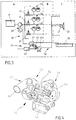
- FIG. 3 shows a schematic of a dual-fluid secondary cooling for a continuous casting plant according to an embodiment.
- the overflow control valves 34 used to drive a water-driven air compressor 60, more precisely, a turbine 61 of the compressor 60.
- the compressor 60 may, for example, a turbine 61, which is designed according to the basic principle of a Francis turbine.
- the compressor 60 is disposed in the distribution room or media room A to utilize the energy of the excess water to compress air, which is then supplied via the air distribution network 50 to the mixing chambers 51 of the nozzles 33.
- the excess water sets a water wheel in the turbine 61 of the compressor 60 in rotary motion.
- a possible component of the compressor 60 may be a torque converter for the low-impact starting.
- the rotational movement of the water wheel is forwarded directly or with the aid of a gear 62 to an air compressor 63.
- the air compressor 63 is part of the compressor 60 and may be designed, for example, as an axial or radial compressor or side channel compressor.
- the air compressor 63 sucks in the air via an air conditioning unit 64 having, for example, a filter and / or a dewatering device and places the air in the air distribution network 50.
- FIG. 4 shows an exemplary water powered air compressor 60 suitable for use with the dual-fluid secondary cooling described.
- the turbine 61, the air compressor 63 and the direct Connection or the gear 62 in between shows the FIG. 4 a water supply port 65 and a water drain port 66, and an air suction port 67 and an air discharge port 68, through which the air compressed by the air compressor 63 is discharged into the air distribution net 50.
- the water-driven (or generally coolant-driven) compressor 60 By the water-driven (or generally coolant-driven) compressor 60, air is sucked in and compressed by excess water energy.
- the energy of the water flow which has been converted into friction in conventional systems on the volume flow control valve 31 or flowed off via the overflow control valve 34 unused, can be used to energetically fully or at least partially support the air compression.
- the water pump (s) 20 By splitting the water circuits for turbine operation and nozzle operation, it is possible to always drive the water pump (s) 20 at the optimum operating point with the highest power, i. at the maximum of the pump characteristic curve, which describes the relationship between the volume flow delivered by the pump and the pressure built up by the pump.
- the rotating parts are in the unproblematic environment of the distribution chamber, unproblematic in terms of air cleanliness, humidity and / or temperature.
- the air treatment and / or filtering by means of the air treatment unit 64 can be realized with relatively little effort.
- water distribution network or “coolant distribution network” and “air distribution network” or “gas distribution network” each designate an arrangement of fluidic devices, such as pipes, pipes, valves, branches, etc., which need not be arranged in the strict sense net or more must have different or a plurality of said facilities.
- the lines for transporting the water and the air according to the embodiments shown in detail go from the FIGS. 1, 2 . 3 and 5 schematically, even if they do not bear the reference numerals for clarity.
- FIG. 5 shows a schematic of a two-fluid secondary cooling for a continuous casting plant according to another embodiment.
- the compressor 60 as an autonomous unit is immediately adjacent to the continuous caster, e.g. in the continuous casting segment C or on the segment support frame or on the cooling chamber wall.
- the unit includes a turbine 61, an air compressor 63, an optional transmission 62, an optional torque converter (not numbered), an air conditioning unit 64, and a bypass valve 69.
- the bypass valve 69 may be self-regulating, for example by being controlled by the applied water pressure.
- the bypass valve 69 may be preset at the nozzle 33 for a given air / water ratio. In order to be able to ensure the variance of the pending water pre-pressure at the bypass valve 69, it is preferable to use a part of the original setting range, for example 80 to 100% of the stroke.
- FIG. 6 showing a continuous casting segment on the side of which a water driven air compressor 60 is mounted.
- there are rotating or sensitive mechanical parts compared to the embodiment of FIG. 3 in a harsher environment (possibly casting powder and / or vapor in the atmosphere, radiating strand, high temperatures) since they are arranged in the continuous casting segment C.
Landscapes
- Engineering & Computer Science (AREA)
- Mechanical Engineering (AREA)
- Continuous Casting (AREA)
Abstract
Description
- Die Erfindung betrifft eine Vorrichtung und ein Verfahren zur Mehrstoff-Sekundärkühlung in einer Stranggießanlage, wobei ein Mehrstoffkühlmittel, vorzugsweise ein Luft/Wasser-Gemisch, in einer Sekundärkühlzone auf Oberflächen des gegossenen Strangs aufgebracht wird.
- Beim Stranggießen von Brammen ist es bekannt, eine Sekundärkühlung des Gießprodukts, d.h. eine Kühlung die nach dem Austritt der Bramme aus der Kokille erfolgt, durchzuführen. Dabei wird ein Kühlmedium, das beispielsweise Wasser oder ein Gemisch aus Luft und Wasser ist, auf die zu kühlenden Metallflächen der Bramme aufgebracht oder aufgesprüht. Der Bramme oder dem gegossenen Strang wird Wärme durch Verdampfen und/oder Erwärmen des Kühlmediums entzogen. Für das Gießen unterschiedlicher Stahlsorten in einem weiten Bereich unterschiedlicher Gießgeschwindigkeiten ist ein großer Stellbereich betreffend die Kühlstärke erforderlich, die von verschiedenen Parametern, darunter der Wasserbeaufschlagungsdichte bestimmt wird.
- Die
Figur 1 zeigt ein Schema einer herkömmlichen Wasser-Sekundärkühlung für eine Stranggießanlage. Hierbei wird Wasser aus einem Reservoir 10 mit Hilfe einer Pumpe 20, die eine einfache oder frequenzgeregelte Wasserpumpe sein kann, in ein Wasserverteilernetz 30 gebracht. Für die Regelung des Wasservolumenstroms werden Regelventile 31, beispielsweise Kolbenventile, verwendet. Die Regelventile 31 können mit einer Ventilsteuerung und/oder einem Volumenstrommessgerät, gemeinsam mit dem Bezugszeichen 32 bezeichnet, ausgestattet sein, um den Volumenstrom über eine Verrohrung hin zu Düsen 33 zu regeln und zu messen. Die Stranggießanlage kann ein oder mehrere sogenannte Überstromregelventile 34 aufweisen, die eine überschüssige Wassermenge zwischen der Wasserpumpe 20 und den Regelventilen 31 abzweigen und in eine Sinterrinne 35 leiten. Die Vorrichtung derFigur 1 ist schematisch in drei Abschnitte unterteilt, wobei das Bezugszeichen A einen feststehenden Anlagenteil, einen Medienraum oder Verteilerraum, das Bezugszeichen C ein Stranggießsegment in der Nähe des gegossenen Strangs, in dem die Düsen 33 zur Kühlmittelabgabe vorgesehen sind, und das Bezugszeichen B einen Abschnitt bezeichnet, in dem eine Verrohrung als Teil des Wasserverteilernetzes 30 das Wasser vom Verteilerraum A zum Stranggießsegment C zuführt. - Eine herkömmliche Wasserdüse 33 mit einfacher Bauart weist eine feste Mündung zur Abgabe des Wassers auf. Dies führt zu einer invarianten Druck/Volumenstrom-Kennlinie, bei der jedem Druck, beispielsweise im Druckbereich von 0,5 bis 12 bar, genau ein Wasservolumenstrompunkt zugeordnet ist. Der gewünschte Wasservolumenstrom wird mit dem oben genannten Regelventil 31 (auch als Volumenstromregelventil bezeichnet) im Verteilerraum eingestellt. In dem genannten Druckbereich von 0,5 bis 12 bar weisen die Einstoffdüsen 33 einen relativ geringen Stellbereich von etwa 1:3,2 bezüglich Wasserdurchfluss auf. Das Wasser-Sekundärkühlsystem ist in diesem Sinne wenig flexibel. Ferner kann die Regelung oder Änderung des Volumenstroms zu einem Energieverlust führen. Denn wenn die Regelventile 31 beispielsweise als Kolbenventile ausgeführt sind, wird insbesondere bei einem niedrigen Wasserverbrauch eine große Menge an Energie des Wasserstroms am Ringdiffusor des Kolbenventils in Reibung umgewandelt. Herkömmliche Flachstrahl- oder Vollkegelsprühbild-Düsen sind entlang standardisierter Volumenstrom- und Strahlwinkelabstufungen unterteilt und gemäß einem Kompromiss bei der Anlagenauslegung dem Düsenteppich der Sekundärkühlzone zugeordnet. Ein weiterer Nachteil der beschriebenen Anlage betrifft den Wartungsaufwand, der zur Beseitigung von Rückständen an den Düsen, insbesondere Kalkablagerungen, erforderlich ist. Solche Ablagerungen treten insbesondere bei geringen Wasservolumenströmen auf. Die kleinen Querschnitte der Düsen setzen sich schnell zu.
- Eine Weiterentwicklung der oben beschriebenen Wasserkühlung besteht darin, die Sekundärkühlung als Zweistoffkühlung mittels eines Luft/Wasser-Gemischs durchzuführen. Dabei wird Wasser in einer Mischkammer mit Luft vorgemischt, und das Gemisch wird einer oder mehreren Düsen zugeführt und als zerstäubtes Zweistoffgemisch ausgegeben. Eine solche Zweistoffkühlung ist beispielsweise in der
DE 100 15 832 A1 beschrieben. - Die
Figur 2 zeigt ein Schema einer herkömmlichen Zweistoff-Sekundärkühlung für eine Stranggießanlage. Dabei sind gleiche, ähnliche oder gleichwirkende Elemente relativ zurFigur 1 mit identischen Bezugszeichen versehen, und auf eine wiederholende Beschreibung dieser Elemente wird teilweise verzichtet, um Redundanzen zu vermeiden. Im Verteilerraum A wird Luft mittels eines strombetriebenen Kompressors 40 verdichtet und in einem Luftverteilernetz 50, das von dem Wasserverteilernetz 30 größtenteils getrennt ist, bis zu einer oder mehreren Mischkammern 51 geleitet. Dort kommen die beiden Verteilernetze zusammen, Wasser und Luft werden in den Mischkammern 51 vermischt und aus den Düsen 33 ausgegeben. - Die Luft bei der Zweistoff-Sekundärkühlung wird zur Wasserstrahlzerstäubung und gleichzeitig zum Einstellen und Aufrechterhalten des Öffnungswinkels des Kühlstrahls an der Düse 33 genutzt, bei verschiedenen Druckeinstellungen, insbesondere bei einem niedrigen Wasserdruck. Im Unterschied zur "reinen" Wasserkühlung der
Figur 1 wird die Strang- oder Brammenoberfläche mit einem Aerosol mit sehr feinen Wassertröpfchen besprüht. Der Stellbereich hinsichtlich der Wassermenge lässt sich dadurch etwa bis auf 1:14 erweitern. Nachteilig, allerdings, sind eine schlechte Energieeffizienz und daraus folgende hohe Investitions- und Betriebskosten zur Implementierung der Zweistoff-Sekundärkühlung, dich sich insbesondere aus den Strom- und Energiekosten für die Luftverdichtung mittels des Kompressors 40 ergeben. - Die
EP 2 527 061 A1 beschreibt eine technische Variante der Einstoff-Sekundärkühlung, bei der Schaltventile zum intermittierenden Öffnen und Schließen des Volumenstroms eines Kühlmittels eingesetzt werden. Die Volumenstromregelung erfolgt mit Hilfe einer Pulsweitenmodulation. Die Verwendung von Magnetventilen und anderen elektronischen Komponenten erfordert einen hohen Wartungs- und Instandhaltungsaufwand, insbesondere beim Einsatz unter den rauen Bedingungen des Stranggießens. Zudem ist bei dieser Art der Volumenstromregelung die Kühlwirkung zyklisch und kann zu erhöhten thermischen Spannungen führen, die wiederrum eine vermehrte Rissbildung im Gießprodukt zur Folge haben können. - Eine Aufgabe der Erfindung besteht darin, eine Vorrichtung und ein Verfahren zur Mehrstoff-Sekundärkühlung für eine Stranggießanlage anzugeben, die wenigstens einen der oben genannten technischen Nachteile überwinden. Insbesondere sollen die Vorrichtung und das Verfahren energieeffizient und flexibel sein, d.h. einen großen Einstellbereich des Volumenstroms und/oder anderer Parameter gewährleisten, und ein sicheres und dauerhaftes Spritzbild ermöglichen.
- Gelöst wird die Aufgabe mit einer Vorrichtung mit den Merkmalen des Anspruchs 1 sowie einem Verfahren mit den Merkmalen des Anspruchs 9. Vorteilhafte Weiterbildungen folgen aus den Unteransprüchen, der folgenden Darstellung der Erfindung sowie der Beschreibung bevorzugter Ausführungsbeispiele.
- Die erfindungsgemäße Vorrichtung dient der Mehrstoff-Sekundärkühlung, insbesondere Zweistoff-Sekundärkühlung, für eine, bevorzugt in einer Stranggießanlage. Die Vorrichtung weist wenigstens eine Düse zum Abgeben eines Mehrstoffkühlmittels auf Oberflächen des gegossenen Strangs auf. Als "gegossener Strang" wird hier jedwedes gegossenes oder im gießen befindliche Gießprodukt, beispielsweise eine Bramme, bezeichnet, das einer Sekundärkühlung zu unterziehen ist. Insbesondere kommt es nicht auf die Form oder die konkrete Zusammensetzung des Gießprodukts oder auf dessen Bearbeitungsstadium an, insoweit es die Gießkokille verlassen hat. Das Mehrstoffkühlmittel hat wenigstens zwei Komponenten, ein flüssiges Kühlmittel und ein Gas. Vorzugsweise weist das flüssige Kühlmittel Wasser auf oder ist Wasser, und vorzugsweise weist das Gas Luft auf oder ist Luft. In diesem Fall kann die Luft etwa zur Wasserzerstäubung und vorzugsweise zum Modellieren und/oder Einhalten des Öffnungswinkels des Kühlstrahls genutzt oder mitgenutzt werden. Das flüssige Kühlmittel und das Gas werden in wenigstens einer Mischkammer, die Teil der Düse ist oder mit der Düse strömungstechnisch verbunden ist, zum Mehrstoffkühlmittel vermischt. Die Vorrichtung weist ferner ein Kühlmittelverteilernetz auf, mit wenigstens einer Kühlmittelleitung zum Transport des flüssigen Kühlmittels zur Mischkammer und wenigstens einem Regelventil zur Regelung des der Mischkammer zuzuführenden Volumenstroms des flüssigen Kühlmittels. Ferner weist die Vorrichtung ein Gasverteilernetz mit wenigstens einer Gasleitung zum Transport des Gases zur Mischkammer auf. Die Begriffe "Kühlmittelverteilernetz" und "Gasverteilernetz" bezeichnen jeweils eine Anordnung strömungstechnischer Einrichtungen, wie etwa Leitungen, Rohre, Ventile, Abzweigungen usw., wobei diese weder im strengen Sinne netzartig angeordnet sein müssen noch mehrere unterschiedliche oder eine Vielzahl der genannten Einrichtungen aufweisen müssen. Für die vorliegende Erfindung ist es wichtig, dass das Kühlmittelverteilernetz ein oder mehrere Regelventile zur Regelung des Volumenstroms des flüssigen Kühlmittels aufweist und dass die beiden Verteilernetze an einer oder mehreren Mischkammern miteinander strömungstechnisch kommunizieren. Im einfachsten Fall weist das Kühlmittelverteilernetz ein Regelventil und eine Leitung, und das Gasverteilernetz eine Leitung auf.
- Erfindungsgemäß weist die Vorrichtung ferner einen kühlmittelbetriebenen Kompressor auf, der eine Turbine und einen Gasverdichter hat. Die Turbine und der Gasverdichter sind miteinander verbunden, vorzugsweise mechanisch. Der Kompressor ist so eingerichtet, dass die Turbine von einem Teil des flüssigen Kühlmittels in Drehung versetzt wird, wodurch der Gasverdichter Gas ansaugt, verdichtet und dem Gasverteilernetz zuführt.
- Durch den kühlmittelbetriebenen Kompressor wird Gas durch einen Teil der kinetischen Energie des flüssigen Kühlmittels angesaugt und verdichtet. Hierbei wird Energie genutzt, die in herkömmlichen Anlagen etwa am Volumenstromregelventil in Reibung umgewandelt wird oder über ein Überstromregelventil ungenutzt abfließt. Somit wird gemäß der Erfindung diese überschüssige Energie des Flüssigkühlmittelstroms genutzt, um die Gasverdichtung durchzuführen, d.h. energetisch vollständig oder teilweise zu unterstützen. Dadurch kann die Kühlung energieeffizienter durchgeführt werden. Neben einer verbesserten Kühlwirkung kann durch die Zerstäubung des flüssigen Kühlmittels mittels des Gases ein Zusetzen der Düsen durch Ablagerungen, wie etwa Kalk, vermindert werden. Das beschriebene Sekundärkühlsystem erlaubt einen großen Stellbereich und ein sicheres und dauerhaftes Spritzbild. Die Umrüstung einer herkömmlichen Zweistoff-Sekundärkühlung auf eine solche flüssigkühlmittelunterstützte Gasverdichtung ist auf einfache Weise möglich, denn die vorhandene Leitung/Ventil/Mischkammer/Düsen-Architektur kann in wesentlichen Teilen weitergenutzt werden. Wenn die Gasverdichtung herkömmlich mittels eines strombetriebenen Kompressors durchgeführt wurde, kann dieser mit dem oben beschriebenen flüssigkeitsbetriebenen Kompressor ersetzt oder ergänzt werden.
- Auch wenn die strömungstechnischen Beziehungen zum Zweck der übersichtlichen Darstellung oft im Singular, etwa anhand eines Regelventils, einer Mischkammer, einer Düse, eines Kompressors usw. beschrieben werden, ist die Erfindung und deren bevorzugte Ausführungsformen darauf nicht beschränkt. Auf analoge und bevorzugte Weise können mehrere Regelventile und/oder mehrere Mischkammern und/oder mehrere Düsen und/oder mehrere Kompressoren und/oder mehrere Pumpen (siehe unten) usw. vorgesehen sein.
- Vorzugsweise weist die Vorrichtung ferner wenigstens eine Pumpe auf, die flüssiges Kühlmittel in das Kühlmittelverteilernetz pumpt, wobei das flüssige Kühlmittel zum Antreiben der Turbine aus einem Leitungsabschnitt zwischen der Pumpe und dem Regelventil abgezweigt wird. Damit sind die Flüssigkühlmittelkreisläufe für den Turbinenbetrieb und Düsenbetrieb gesplittet, wodurch es möglich ist, die Pumpe stets am optimalen Betriebspunkt mit der höchsten Leistung zu fahren.
- Vorzugsweise ist das wenigstens eine Regelventil ein Kolbenventil mit einem Ringdiffusor. Insbesondere bei einem niedrigen Flüssigkühlmittelverbrauch wird im Fall eines Kolbenventils eine große Menge an Energie des Flüssigkeitsstroms am Ringdiffusor in Reibung umgewandelt, die dadurch gewinnbringend zur Verdichtung des Gases mittels des Kompressors genutzt werden kann.
- Vorzugsweise sind die Turbine und der Gasverdichter über ein Getriebe miteinander verbunden, wodurch die Flexibilität der Vorrichtung im Hinblick auf die Verdichtung des Gases und damit auf die Herstellung des Zweistoffkühlmittels verbessert wird.
- Vorzugsweise weist die Vorrichtung eine Gasaufbereitungseinheit auf, die einen Filter und/oder eine Entwässerungsvorrichtung hat, zur Behandlung des in das Gasverteilernetz zuzuführenden Gases, wobei die Gasaufbereitungseinheit in diesem Fall besonders bevorzugt in Strömungsrichtung vor dem Kompressor angeordnet ist. Die Gas- insbesondere Luftaufbereitung lässt sich mit relativ kleinem Aufwand realisieren, wodurch sich die Anlage vor Fremdkörpern schützen und deren Zuverlässigkeit damit erhöhen lässt.
- Vorzugsweise weist die Vorrichtung wenigstens ein Bypass-Ventil in Strömungsrichtung vor dem Kompressor auf, zum Aufteilen des Kühlmittels zum Kompressor und zur Düse, wobei das Bypass-Ventil vorzugsweise ein selbstregelndes Ventil ist, das vom anliegenden Flüssigkühlmittelvordruck gesteuert wird und für ein vorgegebenes Gas/Kühlmittel-Verhältnis an der Düse voreingestellt ist. Auf diese Weise kann eine autonome Steuerung oder autonome Teilsteuerung der Vorrichtung realisiert werden, insbesondere lässt sich der Kompressor in diesem Fall als autonome Einheit unmittelbar in der Nähe der Stranggießanlage, z.B. an einem Stranggießsegment oder Segmenttragrahmen oder an der Kühlkammerwand, anordnen, wodurch eine herkömmliche Anlage auf noch einfachere Weise mit der vorliegenden Erfindung nachrüstbar ist.
- Vorzugsweise weist die Vorrichtung einen Verteilerraum und ein davon getrenntes Stranggießsegment auf, wobei das wenigstens eine Regelventil und der Kompressor im Verteilerraum angeordnet sind und die wenigstens eine Düse im Stranggießsegment angeordnet ist. Die Trennung ist hierbei beispielsweise bezüglich der Temperatur und/oder Reinheit der Atmosphäre und/oder Feuchtigkeit zu verstehen. Somit befinden sich gemäß dieser bevorzugten Ausführungsform drehende oder auf andere Weise empfindlichere Teile in einer weniger rauen Umgebung, d.h. dem Verteilerraum, im Vergleich zum Stranggießsegment. Dadurch lässt sich die Zuverlässigkeit der Anlage erhöhen und der Wartungsaufwand verringern.
- Andererseits kann es, wie oben dargelegt, gerade im Hinblick auf die Modularität oder Nachrüstbarkeit sinnvoll sein, den Kompressor in der Nähe des zu kühlenden Strangs anzuordnen, wobei es in diesem Fall besonders bevorzugt ist, das wenigstens eine Regelventil im Verteilerraum und den Kompressor und die wenigstens eine Düse im Stranggießsegment anzuordnen.
- Die oben beschriebene Aufgabe der Erfindung wird ferner mit einem Verfahren gelöst, das aufweist: Transportieren eines flüssigen Kühlmittels, vorzugsweise Wasser, mittels wenigstens einer Kühlmittelleitung durch wenigstens ein Regelventil zur Regelung des Volumenstroms des flüssigen Kühlmittels in wenigstens eine Mischkammer; Transportieren eines Gases mittels wenigstens einer Gasleitung in die wenigstens eine Mischkammer, in der das flüssige Kühlmittel und das Gas zu einem Mehrstoffkühlmittel vermischt werden; Abgeben des Mehrstoffkühlmittels durch wenigstens eine Düse auf Oberflächen des gegossenen Strangs. Erfindungsgemäß wird das Gas mittels eines Kompressors komprimiert, der von einem Teil des flüssigen Kühlmittels angetrieben wird. Die technischen Wirkungen und Vorteile des Verfahrens entsprechen denen, die oben mit Bezug auf die Vorrichtung beschrieben sind.
- Besonders bevorzugt wird das Verfahren mittels der erfindungsgemäßen Vorrichtung oder einer der beschriebenen bevorzugten Ausführungsvarianten durchgeführt.
- Die beschriebenen Vorrichtungen und Verfahren dienen in erster Linie der Mehrstoff-Sekundärkühlung, insbesondere Zweistoff-Sekundärkühlung, in einer Stranggießanlage. Doch die Erfindung kann gegebenenfalls auch in anderen Anlagen eingesetzt werden, soweit eine Mehrstoffkühlung durchgeführt wird.
- Weitere Vorteile und Merkmale der vorliegenden Erfindung sind aus der folgenden Beschreibung bevorzugter Ausführungsbeispiele ersichtlich. Die dort beschriebenen Merkmale können alleinstehend oder in Kombination mit einem oder mehreren der oben dargelegten Merkmale umgesetzt werden, insofern sich die Merkmale nicht widersprechen. Die folgende Beschreibung der bevorzugten Ausführungsbeispiele erfolgt dabei unter Bezugnahme auf die begleitenden Zeichnungen.
-
- Die
Figur 1 zeigt ein Schema einer herkömmlichen Wasser-Sekundärkühlung für eine Stranggießanlage. - Die
Figur 2 zeigt ein Schema einer herkömmlichen Zweistoff-Sekundärkühlung für eine Stranggießanlage. - Die
Figur 3 zeigt ein Schema einer Zweistoff-Sekundärkühlung für eine Stranggießanlage gemäß einem Ausführungsbeispiel der Erfindung. - Die
Figur 4 zeigt einen wasserbetriebenen Luftkompressor, der zur Anwendung bei einer Zweistoff-Sekundärkühlung geeignet ist. - Die
Figur 5 zeigt ein Schema einer Zweistoff-Sekundärkühlung für eine Stranggießanlage gemäß einem weiteren Ausführungsbeispiel der Erfindung. - Die
Figur 6 ist eine perspektivische Ansicht auf ein Stranggießsegment, an dessen Seite ein wasserbetriebener Luftkompressor angebracht ist. - Im Folgenden werden bevorzugte Ausführungsbeispiele anhand der Figuren beschrieben. Dabei sind gleiche, ähnliche oder gleichwirkende Elemente mit identischen Bezugszeichen versehen, und auf eine wiederholende Beschreibung dieser Elemente wird teilweise verzichtet, um Redundanzen zu vermeiden. Dies gilt auch mit Bezug auf die oben, im Abschnitt "Hintergrund der Erfindung" beschriebenen
Figuren 1 und 2 . - Die
Figur 3 zeigt ein Schema einer Zweistoff-Sekundärkühlung für eine Stranggießanlage gemäß einem Ausführungsbeispiel. - Im Unterschied zu dem in der
Figur 2 dargestellten herkömmlichen Zweistoff-Sekundärkühlsystem wird überschüssige Wasserenergie, die beispielsweise an den Überstromregelventilen 34 abgefallen ist, dazu genutzt, einen wasserbetriebenen Luftkompressor 60, genauer gesagt eine Turbine 61 des Kompressors 60, anzutreiben. Der Kompressor 60 kann dazu beispielsweise eine Turbine 61, die nach dem Grundprinzip einer Francis-Turbine ausgeführt ist, aufweisen. - In dem vorliegenden Ausführungsbeispiel ist der Kompressor 60 im Verteilerraum oder Medienraum A angeordnet, um die Energie des überschüssigen Wassers zur Verdichtung von Luft zu nutzen, die anschließend über das Luftverteilernetz 50 den Mischkammern 51 der Düsen 33 zugeführt wird. Dazu setzt das überschüssige Wasser ein Wasserrad in der Turbine 61 des Kompressors 60 in Drehbewegung. Ein möglicher Bestandteil des Kompressors 60 kann dabei ein Drehmomentumsetzer für das stoßarme Anfahren sein. Die Drehbewegung des Wasserrads wird direkt oder mit Hilfe eines Getriebes 62 an einen Luftverdichter 63 weitergeleitet. Der Luftverdichter 63 ist Teil des Kompressors 60 und kann beispielsweise als Axialverdichter oder Radialverdichter oder Seitenkanalverdichter ausgeführt sein. Der Luftverdichter 63 saugt die Luft über eine Luftaufbereitungseinheit 64 an, die beispielsweise einen Filter und/oder eine Entwässerungsvorrichtung hat, und stellt die Luft ins Luftverteilernetz 50.
- Die
Figur 4 zeigt einen beispielhaften wasserbetriebenen Luftkompressor 60, der zur Anwendung der beschriebenen Zweistoff-Sekundärkühlung geeignet ist. Neben den genannten Bestandteilen, d.h. der Turbine 61, dem Luftverdichter 63 und der direkten Verbindung oder dem Getriebe 62 dazwischen, zeigt dieFigur 4 einen Wasserzufuhranschluss 65 und einen Wasserabflussanschluss 66, sowie einen Luftansauganschluss 67 und einen Luftabgabeanschluss 68, durch den die vom Luftverdichter 63 komprimierte Luft in das Luftverteilernetz 50 abgegeben wird. - Durch den wasserbetriebenen (oder allgemein kühlmittelbetriebenen) Kompressor 60 wird Luft durch überschüssige Wasserenergie angesaugt und verdichtet. Somit kann die Energie des Wasserstroms, die in herkömmlichen Anlagen am Volumenstromregelventil 31 in Reibung umgewandelt wurde oder über das Überstromregelventil 34 ungenutzt abfloss, genutzt werden, um die Luftverdichtung energetisch vollständig oder zumindest teilweise zu unterstützen. Dadurch dass die Wasserkreisläufe für den Turbinenbetrieb und Düsenbetrieb gesplittet sind, ist es möglich, die Wasserpumpe(n) 20 immer am optimalen Betriebspunkt mit der höchsten Leistung zu fahren, d.h. am Maximum der Pumpenkennlinie, die den Zusammenhang zwischen dem von der Pumpe geförderten Volumenstrom und dem dabei von der Pumpe aufgebauten Druck beschreibt. Gemäß dem dargestellten Ausführungsbeispiel befinden sich die drehenden Teile in der unproblematischen Umgebung des Verteilerraums, unproblematisch etwa hinsichtlich Luftsauberkeit, Feuchtigkeit und/oder Temperatur. Die Luftaufbereitung und/oder Filterung mittels der Luftaufbereitungseinheit 64 lässt sich mit relativ kleinem Aufwand realisieren.
- Die Bezeichnungen "Wasserverteilernetz" bzw. "Kühlmittelverteilernetz" und "Luftverteilernetz" bzw. "Gasverteilernetz" bezeichnen jeweils eine Anordnung strömungstechnischer Einrichtungen, wie etwa Leitungen, Rohre, Ventile, Abzweigungen usw., wobei diese weder im strengen Sinne netzartig angeordnet sein müssen noch mehrere unterschiedliche oder eine Vielzahl der genannten Einrichtungen aufweisen müssen. Die Leitungen zum Transport des Wassers und der Luft gemäß den detailliert dargestellten Ausführungsbeispielen gehen aus den
Figuren 1, 2 ,3 und5 schematisch hervor, auch wenn sie der Übersichtlichkeit halber keine Bezugszeichen tragen. - Die
Figur 5 zeigt ein Schema einer Zweistoff-Sekundärkühlung für eine Stranggießanlage gemäß einem weiteren Ausführungsbeispiel. - Gemäß diesem Ausführungsbeispiel ist der Kompressor 60 als autonome Einheit unmittelbar in der Nähe der Stranggießanlage, z.B. im Stranggießsegment C oder am Segmenttragrahmen oder an der Kühlkammerwand, angeordnet. Die Einheit weist eine Turbine 61, einen Luftverdichter 63, ein optionales Getriebe 62, einen optionalen Drehmomentumsetzer (ohne Bezugszeichen), eine Luftaufbereitungseinheit 64 und ein Bypass-Ventil 69 auf. Das Bypass-Ventil 69 kann selbstregelnd ausgeführt sein, indem es beispielsweise vom anliegenden Wasservordruck gesteuert wird. Das Bypass-Ventil 69 kann für ein vorgegebenes Luft/Wasser-Verhältnis an der Düse 33 voreingestellt sein. Um die Varianz des anstehenden Wasservordrucks am Bypass-Ventil 69 gewährleisten zu können, ist es bevorzugt, einen Teil des originalen bzw. ursprünglichen Stellbereichs zu verwenden, beispielsweise 80 bis 100% des Hubs.
- Gegenüber dem Ausführungsbeispiel der
Figur 3 kann in dem autonomen Ausführungsbeispiel derFigur 5 der Verrohrungsaufwand geringer gehalten werden. Beispielsweise sind der Materialaufwand, Montageaufwand und die Stillstanddauer für die Montage der Luftleitungen geringer. Das geht auch aus derFigur 6 hervor, die ein Stranggießsegment zeigt, an dessen Seite ein wasserbetriebener Luftkompressor 60 angebracht ist. Demgegenüber befinden sich drehende oder empfindliche mechanische Teile im Vergleich zum Ausführungsbeispiel derFigur 3 in einer raueren Umgebung (möglicherweise Gießpulver und/oder Dampf in der Atmosphäre, strahlender Strang, hohe Temperaturen), da sie im Stranggießsegment C angeordnet sind. - Soweit anwendbar, können alle einzelnen Merkmale, die in den Ausführungsbeispielen dargestellt sind, miteinander kombiniert und/oder ausgetauscht werden, ohne den Bereich der Erfindung zu verlassen.
-
- 10
- Reservoir
- 20
- Pumpe/Wasserpumpe
- 30
- Wasserverteilernetz/Kühlmittelverteilernetz
- 31
- Regelventil
- 32
- Ventilsteuerung/Volumenstrommessgerät
- 33
- Düse
- 34
- Überstromregelventile
- 35
- Sinterrinne
- 40
- strombetriebener Kompressor
- 50
- Luftverteilernetz/Gasverteilernetz
- 51
- Mischkammer
- 60
- kühlmittelbetriebener Kompressor
- 61
- Turbine
- 62
- Getriebe
- 63
- Luftverdichter/Gasverdichter
- 64
- Luftaufbereitungseinheit/Gasaufbereitungseinheit
- 65
- Wasserzufuhranschluss
- 66
- Wasserabflussanschluss
- 67
- Luftansauganschluss
- 68
- Luftabgabeanschluss
- 69
- Bypass-Ventil
- A
- Verteilerraum/Medienraum
- B
- Verrohrung
- C
- Segment der Stranggießanlage, an dem eine Sekundärkühlung stattfindet
Claims (10)
- Vorrichtung zur Mehrstoff-Sekundärkühlung für eine Stranggießanlage, wobei die Vorrichtung aufweist:wenigstens eine Düse (33) zum Abgeben eines Mehrstoffkühlmittels auf Oberflächen des gegossenen Strangs;wenigstens eine Mischkammer (51), die Teil der Düse (33) ist oder mit der Düse (33) strömungstechnisch verbunden ist und in der ein flüssiges Kühlmittel, vorzugsweise Wasser, und ein Gas, vorzugsweise Luft, zum Mehrstoffkühlmittel vermischt werden;ein Kühlmittelverteilernetz (30) mit wenigstens einer Kühlmittelleitung zum Transport des flüssigen Kühlmittels zur Mischkammer (51) und wenigstens einem Regelventil (31) zur Regelung des der Mischkammer (51) zuzuführenden Volumenstroms des flüssigen Kühlmittels; undein Gasverteilernetz (50) mit wenigstens einer Gasleitung zum Transport des Gases zur Mischkammer (51);dadurch gekennzeichnet, dass
die Vorrichtung einen kühlmittelbetriebenen Kompressor (60) mit einer Turbine (61) und einem mit dieser verbundenen Gasverdichter (63) aufweist, wobei der Kompressor (60) so eingerichtet ist, dass die Turbine (61) von einem Teil des flüssigen Kühlmittels in Drehung versetzt wird, wodurch der Gasverdichter (63) Gas ansaugt, verdichtet und dem Gasverteilernetz (50) zuführt. - Vorrichtung nach Anspruch 1, dadurch gekennzeichnet, dass diese wenigstens eine Pumpe (20) aufweist, die flüssiges Kühlmittel in das Kühlmittelverteilernetz (30) pumpt, wobei das flüssige Kühlmittel zum Antreiben der Turbine (61) aus einem Leitungsabschnitt zwischen der Pumpe (20) und dem Regelventil (31) abgezweigt wird.
- Vorrichtung nach Anspruch 1 oder 2, dadurch gekennzeichnet, dass das wenigstens eine Regelventil (31) ein Kolbenventil mit einem Ringdiffusor oder ein V-Ball Ventil ohne Ringdiffusor ist.
- Vorrichtung nach einem der vorigen Ansprüche, dadurch gekennzeichnet, dass die Turbine (61) und der Gasverdichter (63) über ein Getriebe (62) miteinander verbunden sind.
- Vorrichtung nach einem der vorigen Ansprüche, dadurch gekennzeichnet, dass diese eine Gasaufbereitungseinheit (64) aufweist, die einen Filter und/oder eine Entwässerungsvorrichtung hat, zur Behandlung des in das Gasverteilernetz (50) zuzuführenden Gases, wobei die Gasaufbereitungseinheit (64) vorzugsweise in Strömungsrichtung vor dem Kompressor (60) angeordnet ist.
- Vorrichtung nach einem der vorigen Ansprüche, dadurch gekennzeichnet, dass diese wenigstens ein Bypass-Ventil (69) in Strömungsrichtung vor dem Kompressor (60) aufweist, zum Aufteilen des Kühlmittels zum Kompressor (60) und zur Düse (33), wobei das Bypass-Ventil (69) vorzugsweise ein selbstregelndes Ventil ist, das vom anliegenden Flüssigkühlmittelvordruck gesteuert wird und für ein vorgegebenes Gas/Kühlmittel-Verhältnis an der Düse (33) voreingestellt ist.
- Vorrichtung nach einem der vorigen Ansprüche, dadurch gekennzeichnet, dass diese einen Verteilerraum (A) und ein davon getrenntes Stranggießsegment (C) aufweist, wobei das wenigstens eine Regelventil (31) und der Kompressor (60) im Verteilerraum (A) angeordnet sind und die wenigstens eine Düse (33) im Stranggießsegment (C) angeordnet ist.
- Vorrichtung nach einem der Ansprüche 1 bis 6, dadurch gekennzeichnet, dass diese einen Verteilerraum (A) und ein davon getrenntes Stranggießsegment (C) aufweist, wobei das wenigstens eine Regelventil (31) im Verteilerraum (A) angeordnet ist und der Kompressor (60) und die wenigstens eine Düse (33) im Stranggießsegment (C) angeordnet sind.
- Verfahren zur Mehrstoff-Sekundärkühlung in einer Stranggießanlage, wobei das Verfahren aufweist:Transportieren eines flüssigen Kühlmittels, vorzugsweise Wasser, mittels wenigstens einer Kühlmittelleitung durch wenigstens ein Regelventil (31) zur Regelung des Volumenstroms des flüssigen Kühlmittels in wenigstens eine Mischkammer (51);Transportieren eines Gases mittels wenigstens einer Gasleitung in die wenigstens eine Mischkammer (51), in der das flüssige Kühlmittel und das Gas zu einem Mehrstoffkühlmittel vermischt werden;Abgeben des Mehrstoffkühlmittels durch wenigstens eine Düse (33) auf Oberflächen des gegossenen Strangs;dadurch gekennzeichnet, dass
das Gas mittels eines Kompressors (60) komprimiert wird, der von einem Teil des flüssigen Kühlmittels angetrieben wird. - Verfahren nach Anspruch 9, dadurch gekennzeichnet, dass dieses mit einer Vorrichtung nach einem der Ansprüche 1 bis 8 ausgeführt wird.
Applications Claiming Priority (2)
| Application Number | Priority Date | Filing Date | Title |
|---|---|---|---|
| DE102016207403 | 2016-04-29 | ||
| DE102016215209.2A DE102016215209A1 (de) | 2016-04-29 | 2016-08-16 | Zweistoff-Sekundärkühlung für eine Stranggießanlage |
Publications (2)
| Publication Number | Publication Date |
|---|---|
| EP3238857A1 true EP3238857A1 (de) | 2017-11-01 |
| EP3238857B1 EP3238857B1 (de) | 2019-07-24 |
Family
ID=58489257
Family Applications (1)
| Application Number | Title | Priority Date | Filing Date |
|---|---|---|---|
| EP17164822.3A Active EP3238857B1 (de) | 2016-04-29 | 2017-04-04 | Zweistoff-sekundärkühlung für eine stranggiessanlage |
Country Status (1)
| Country | Link |
|---|---|
| EP (1) | EP3238857B1 (de) |
Cited By (5)
| Publication number | Priority date | Publication date | Assignee | Title |
|---|---|---|---|---|
| CN108080592A (zh) * | 2018-01-19 | 2018-05-29 | 山东钢铁集团日照有限公司 | 一种快速清洗连铸二冷过滤器、喷杆、喷嘴的系统和方法 |
| CN108356241A (zh) * | 2018-03-30 | 2018-08-03 | 上海梅山钢铁股份有限公司 | 一种铸坯宽面冷却精准控制方法 |
| CN109752624A (zh) * | 2018-12-24 | 2019-05-14 | 紫光华山信息技术有限公司 | 液冷流路通断检测方法及装置 |
| CN111531144A (zh) * | 2020-05-15 | 2020-08-14 | 河钢乐亭钢铁有限公司 | 一种超宽流量及拉速变化范围的连铸喷嘴水流量控制方法 |
| AT523701A1 (de) * | 2020-03-12 | 2021-10-15 | Primetals Technologies Austria GmbH | Zweistoff-Schaftdüse mit verringerter Verstopfungsneigung |
Citations (5)
| Publication number | Priority date | Publication date | Assignee | Title |
|---|---|---|---|---|
| DE2444794A1 (de) * | 1974-09-19 | 1976-04-01 | Demag Ag | Verfahren zum kuehlen des in einer stahlstranggiessanlage erzeugten stranges |
| GB1453969A (en) * | 1972-12-05 | 1976-10-27 | Concast Ag | Method and apparatus for continious casting |
| JPH01271049A (ja) * | 1988-04-22 | 1989-10-30 | Nippon Steel Corp | 連続鋳造における2次冷却方法 |
| DE10015832A1 (de) | 1999-04-30 | 2001-03-15 | Voest Alpine Ind Anlagen | Verfahren zum Verteilen einer feinzerstäubten Flüssigkeit sowie Einrichtung hierzu |
| EP2527061A1 (de) | 2011-05-27 | 2012-11-28 | Siemens VAI Metals Technologies GmbH | Verfahren zur Kühlung eines metallischen Strangs und Schaltventil zum intermittierenden Öffnen und Schließen eines Volumenstroms eines Kühlmediums |
-
2017
- 2017-04-04 EP EP17164822.3A patent/EP3238857B1/de active Active
Patent Citations (5)
| Publication number | Priority date | Publication date | Assignee | Title |
|---|---|---|---|---|
| GB1453969A (en) * | 1972-12-05 | 1976-10-27 | Concast Ag | Method and apparatus for continious casting |
| DE2444794A1 (de) * | 1974-09-19 | 1976-04-01 | Demag Ag | Verfahren zum kuehlen des in einer stahlstranggiessanlage erzeugten stranges |
| JPH01271049A (ja) * | 1988-04-22 | 1989-10-30 | Nippon Steel Corp | 連続鋳造における2次冷却方法 |
| DE10015832A1 (de) | 1999-04-30 | 2001-03-15 | Voest Alpine Ind Anlagen | Verfahren zum Verteilen einer feinzerstäubten Flüssigkeit sowie Einrichtung hierzu |
| EP2527061A1 (de) | 2011-05-27 | 2012-11-28 | Siemens VAI Metals Technologies GmbH | Verfahren zur Kühlung eines metallischen Strangs und Schaltventil zum intermittierenden Öffnen und Schließen eines Volumenstroms eines Kühlmediums |
Cited By (8)
| Publication number | Priority date | Publication date | Assignee | Title |
|---|---|---|---|---|
| CN108080592A (zh) * | 2018-01-19 | 2018-05-29 | 山东钢铁集团日照有限公司 | 一种快速清洗连铸二冷过滤器、喷杆、喷嘴的系统和方法 |
| CN108356241A (zh) * | 2018-03-30 | 2018-08-03 | 上海梅山钢铁股份有限公司 | 一种铸坯宽面冷却精准控制方法 |
| CN109752624A (zh) * | 2018-12-24 | 2019-05-14 | 紫光华山信息技术有限公司 | 液冷流路通断检测方法及装置 |
| CN109752624B (zh) * | 2018-12-24 | 2021-04-06 | 新华三信息技术有限公司 | 液冷流路通断检测方法及装置 |
| AT523701A1 (de) * | 2020-03-12 | 2021-10-15 | Primetals Technologies Austria GmbH | Zweistoff-Schaftdüse mit verringerter Verstopfungsneigung |
| AT523701B1 (de) * | 2020-03-12 | 2024-04-15 | Primetals Technologies Austria GmbH | Zweistoff-Schaftdüse mit verringerter Verstopfungsneigung |
| CN111531144A (zh) * | 2020-05-15 | 2020-08-14 | 河钢乐亭钢铁有限公司 | 一种超宽流量及拉速变化范围的连铸喷嘴水流量控制方法 |
| CN111531144B (zh) * | 2020-05-15 | 2021-07-23 | 河钢乐亭钢铁有限公司 | 一种超宽流量及拉速变化范围的连铸喷嘴水流量控制方法 |
Also Published As
| Publication number | Publication date |
|---|---|
| EP3238857B1 (de) | 2019-07-24 |
Similar Documents
| Publication | Publication Date | Title |
|---|---|---|
| EP3238857B1 (de) | Zweistoff-sekundärkühlung für eine stranggiessanlage | |
| EP3111148B1 (de) | Verfahren zur trocknung von schüttgut | |
| DE102009006704A1 (de) | Verfahren zum Betreiben einer Anlage und eine Anlage zur Herstellung von Faser-, MDF, HDF, Holzwerkstoff- oder Kunststoffplatten aus Fasern oder faserähnlichem Material | |
| DE102007007090A1 (de) | Gasturbine mit Kühlluft-Übertragungssystem | |
| DE102008004911A1 (de) | Verfahren zur Regelung der Sekundärkühlung von Stranggießanlagen | |
| WO2018108746A1 (de) | Vorrichtung zum befeuchten eines luftstroms | |
| EP1094911B1 (de) | Verfahren und vorrichtung zum herstellen von weichlotpulver | |
| EP3300486A1 (de) | Verfahren und vorrichtung zum kühlen von extrudierten profilen | |
| DE102008039466A1 (de) | Verfahren und Streustation zur Herstellung einer Streugutmatte aus rieselfähigem Streugut im Zuge der Herstellung von Holzwerkstoffplatten | |
| DE20221407U1 (de) | Vorrichtung zur Rückkühlung von Kühlmitteln oder Rückkühlmedien oder zur Kältegewinnung | |
| EP2581137A1 (de) | Verfahren zur Flüssigkeitsdispergierung mit einer Aerosolbildung in einem dispersen Luftstrahl und ein mobiler Aerosolgenerator zur Generierung von Aerosolen mit einer regelbaren Dispersität | |
| AT523701B1 (de) | Zweistoff-Schaftdüse mit verringerter Verstopfungsneigung | |
| EP3399264A1 (de) | Sprühfeldsystem für einen kühlturm, kühlturm, verwendung und verfahren | |
| EP2583772A1 (de) | Strangführungsvorrichtung | |
| EP3271133B1 (de) | Behandlungsfluidführung in einer folienreckanlage | |
| DE102016215209A1 (de) | Zweistoff-Sekundärkühlung für eine Stranggießanlage | |
| EP2037198B1 (de) | Anlage zum Trocknen einer Mehrzahl von vorzugsweise mehrteiligen Gipsformen | |
| DE602005003251T2 (de) | Verdampfungssystem für eine Flüssigkeit | |
| EP2611513B1 (de) | Fluidentgasungs-vorrichtung und verfahren zur entgasung von fluiden | |
| DE3323839A1 (de) | Verfahren zum kuehlen von heissen gussteilen sowie vorrichtung zur durchfuehrung des verfahrens | |
| DE102021129749B4 (de) | Anströmungsvorrichtung zum Trocknen und/oder Erwärmen eines Werkstücks | |
| DE102006033007B3 (de) | Vorrichtung zur Luftkühlung von Presssträngen | |
| AT528580B1 (de) | Trocknereinheit zur Trocknung von Kunststoffgranulat | |
| DE102004059069A1 (de) | Vertropfungsanlage | |
| DE102011105647B4 (de) | Pneumatische Vorrichtung oder pneumatisches System mit einer Öler-Vorrichtung |
Legal Events
| Date | Code | Title | Description |
|---|---|---|---|
| PUAI | Public reference made under article 153(3) epc to a published international application that has entered the european phase |
Free format text: ORIGINAL CODE: 0009012 |
|
| STAA | Information on the status of an ep patent application or granted ep patent |
Free format text: STATUS: REQUEST FOR EXAMINATION WAS MADE |
|
| 17P | Request for examination filed |
Effective date: 20170404 |
|
| AK | Designated contracting states |
Kind code of ref document: A1 Designated state(s): AL AT BE BG CH CY CZ DE DK EE ES FI FR GB GR HR HU IE IS IT LI LT LU LV MC MK MT NL NO PL PT RO RS SE SI SK SM TR |
|
| AX | Request for extension of the european patent |
Extension state: BA ME |
|
| STAA | Information on the status of an ep patent application or granted ep patent |
Free format text: STATUS: EXAMINATION IS IN PROGRESS |
|
| 17Q | First examination report despatched |
Effective date: 20171113 |
|
| RBV | Designated contracting states (corrected) |
Designated state(s): AL AT BE BG CH CY CZ DE DK EE ES FI FR GB GR HR HU IE IS IT LI LT LU LV MC MK MT NL NO PL PT RO RS SE SI SK SM TR |
|
| GRAP | Despatch of communication of intention to grant a patent |
Free format text: ORIGINAL CODE: EPIDOSNIGR1 |
|
| STAA | Information on the status of an ep patent application or granted ep patent |
Free format text: STATUS: GRANT OF PATENT IS INTENDED |
|
| INTG | Intention to grant announced |
Effective date: 20190211 |
|
| GRAS | Grant fee paid |
Free format text: ORIGINAL CODE: EPIDOSNIGR3 |
|
| GRAA | (expected) grant |
Free format text: ORIGINAL CODE: 0009210 |
|
| STAA | Information on the status of an ep patent application or granted ep patent |
Free format text: STATUS: THE PATENT HAS BEEN GRANTED |
|
| AK | Designated contracting states |
Kind code of ref document: B1 Designated state(s): AL AT BE BG CH CY CZ DE DK EE ES FI FR GB GR HR HU IE IS IT LI LT LU LV MC MK MT NL NO PL PT RO RS SE SI SK SM TR |
|
| REG | Reference to a national code |
Ref country code: GB Ref legal event code: FG4D Free format text: NOT ENGLISH |
|
| REG | Reference to a national code |
Ref country code: CH Ref legal event code: EP |
|
| REG | Reference to a national code |
Ref country code: DE Ref legal event code: R096 Ref document number: 502017001813 Country of ref document: DE |
|
| REG | Reference to a national code |
Ref country code: AT Ref legal event code: REF Ref document number: 1157600 Country of ref document: AT Kind code of ref document: T Effective date: 20190815 |
|
| REG | Reference to a national code |
Ref country code: IE Ref legal event code: FG4D Free format text: LANGUAGE OF EP DOCUMENT: GERMAN |
|
| REG | Reference to a national code |
Ref country code: NL Ref legal event code: MP Effective date: 20190724 |
|
| REG | Reference to a national code |
Ref country code: LT Ref legal event code: MG4D |
|
| PG25 | Lapsed in a contracting state [announced via postgrant information from national office to epo] |
Ref country code: LT Free format text: LAPSE BECAUSE OF FAILURE TO SUBMIT A TRANSLATION OF THE DESCRIPTION OR TO PAY THE FEE WITHIN THE PRESCRIBED TIME-LIMIT Effective date: 20190724 Ref country code: HR Free format text: LAPSE BECAUSE OF FAILURE TO SUBMIT A TRANSLATION OF THE DESCRIPTION OR TO PAY THE FEE WITHIN THE PRESCRIBED TIME-LIMIT Effective date: 20190724 Ref country code: NO Free format text: LAPSE BECAUSE OF FAILURE TO SUBMIT A TRANSLATION OF THE DESCRIPTION OR TO PAY THE FEE WITHIN THE PRESCRIBED TIME-LIMIT Effective date: 20191024 Ref country code: SE Free format text: LAPSE BECAUSE OF FAILURE TO SUBMIT A TRANSLATION OF THE DESCRIPTION OR TO PAY THE FEE WITHIN THE PRESCRIBED TIME-LIMIT Effective date: 20190724 Ref country code: FI Free format text: LAPSE BECAUSE OF FAILURE TO SUBMIT A TRANSLATION OF THE DESCRIPTION OR TO PAY THE FEE WITHIN THE PRESCRIBED TIME-LIMIT Effective date: 20190724 Ref country code: BG Free format text: LAPSE BECAUSE OF FAILURE TO SUBMIT A TRANSLATION OF THE DESCRIPTION OR TO PAY THE FEE WITHIN THE PRESCRIBED TIME-LIMIT Effective date: 20191024 Ref country code: PT Free format text: LAPSE BECAUSE OF FAILURE TO SUBMIT A TRANSLATION OF THE DESCRIPTION OR TO PAY THE FEE WITHIN THE PRESCRIBED TIME-LIMIT Effective date: 20191125 Ref country code: NL Free format text: LAPSE BECAUSE OF FAILURE TO SUBMIT A TRANSLATION OF THE DESCRIPTION OR TO PAY THE FEE WITHIN THE PRESCRIBED TIME-LIMIT Effective date: 20190724 |
|
| PG25 | Lapsed in a contracting state [announced via postgrant information from national office to epo] |
Ref country code: IS Free format text: LAPSE BECAUSE OF FAILURE TO SUBMIT A TRANSLATION OF THE DESCRIPTION OR TO PAY THE FEE WITHIN THE PRESCRIBED TIME-LIMIT Effective date: 20191124 Ref country code: RS Free format text: LAPSE BECAUSE OF FAILURE TO SUBMIT A TRANSLATION OF THE DESCRIPTION OR TO PAY THE FEE WITHIN THE PRESCRIBED TIME-LIMIT Effective date: 20190724 Ref country code: LV Free format text: LAPSE BECAUSE OF FAILURE TO SUBMIT A TRANSLATION OF THE DESCRIPTION OR TO PAY THE FEE WITHIN THE PRESCRIBED TIME-LIMIT Effective date: 20190724 Ref country code: AL Free format text: LAPSE BECAUSE OF FAILURE TO SUBMIT A TRANSLATION OF THE DESCRIPTION OR TO PAY THE FEE WITHIN THE PRESCRIBED TIME-LIMIT Effective date: 20190724 |
|
| PG25 | Lapsed in a contracting state [announced via postgrant information from national office to epo] |
Ref country code: TR Free format text: LAPSE BECAUSE OF FAILURE TO SUBMIT A TRANSLATION OF THE DESCRIPTION OR TO PAY THE FEE WITHIN THE PRESCRIBED TIME-LIMIT Effective date: 20190724 |
|
| PG25 | Lapsed in a contracting state [announced via postgrant information from national office to epo] |
Ref country code: DK Free format text: LAPSE BECAUSE OF FAILURE TO SUBMIT A TRANSLATION OF THE DESCRIPTION OR TO PAY THE FEE WITHIN THE PRESCRIBED TIME-LIMIT Effective date: 20190724 Ref country code: PL Free format text: LAPSE BECAUSE OF FAILURE TO SUBMIT A TRANSLATION OF THE DESCRIPTION OR TO PAY THE FEE WITHIN THE PRESCRIBED TIME-LIMIT Effective date: 20190724 Ref country code: RO Free format text: LAPSE BECAUSE OF FAILURE TO SUBMIT A TRANSLATION OF THE DESCRIPTION OR TO PAY THE FEE WITHIN THE PRESCRIBED TIME-LIMIT Effective date: 20190724 Ref country code: EE Free format text: LAPSE BECAUSE OF FAILURE TO SUBMIT A TRANSLATION OF THE DESCRIPTION OR TO PAY THE FEE WITHIN THE PRESCRIBED TIME-LIMIT Effective date: 20190724 |
|
| PG25 | Lapsed in a contracting state [announced via postgrant information from national office to epo] |
Ref country code: SM Free format text: LAPSE BECAUSE OF FAILURE TO SUBMIT A TRANSLATION OF THE DESCRIPTION OR TO PAY THE FEE WITHIN THE PRESCRIBED TIME-LIMIT Effective date: 20190724 Ref country code: IS Free format text: LAPSE BECAUSE OF FAILURE TO SUBMIT A TRANSLATION OF THE DESCRIPTION OR TO PAY THE FEE WITHIN THE PRESCRIBED TIME-LIMIT Effective date: 20200224 Ref country code: CZ Free format text: LAPSE BECAUSE OF FAILURE TO SUBMIT A TRANSLATION OF THE DESCRIPTION OR TO PAY THE FEE WITHIN THE PRESCRIBED TIME-LIMIT Effective date: 20190724 Ref country code: SK Free format text: LAPSE BECAUSE OF FAILURE TO SUBMIT A TRANSLATION OF THE DESCRIPTION OR TO PAY THE FEE WITHIN THE PRESCRIBED TIME-LIMIT Effective date: 20190724 |
|
| REG | Reference to a national code |
Ref country code: DE Ref legal event code: R097 Ref document number: 502017001813 Country of ref document: DE |
|
| PLBE | No opposition filed within time limit |
Free format text: ORIGINAL CODE: 0009261 |
|
| STAA | Information on the status of an ep patent application or granted ep patent |
Free format text: STATUS: NO OPPOSITION FILED WITHIN TIME LIMIT |
|
| PG2D | Information on lapse in contracting state deleted |
Ref country code: IS |
|
| 26N | No opposition filed |
Effective date: 20200603 |
|
| PG25 | Lapsed in a contracting state [announced via postgrant information from national office to epo] |
Ref country code: SI Free format text: LAPSE BECAUSE OF FAILURE TO SUBMIT A TRANSLATION OF THE DESCRIPTION OR TO PAY THE FEE WITHIN THE PRESCRIBED TIME-LIMIT Effective date: 20190724 |
|
| PG25 | Lapsed in a contracting state [announced via postgrant information from national office to epo] |
Ref country code: ES Free format text: LAPSE BECAUSE OF FAILURE TO SUBMIT A TRANSLATION OF THE DESCRIPTION OR TO PAY THE FEE WITHIN THE PRESCRIBED TIME-LIMIT Effective date: 20190724 |
|
| PG25 | Lapsed in a contracting state [announced via postgrant information from national office to epo] |
Ref country code: MC Free format text: LAPSE BECAUSE OF FAILURE TO SUBMIT A TRANSLATION OF THE DESCRIPTION OR TO PAY THE FEE WITHIN THE PRESCRIBED TIME-LIMIT Effective date: 20190724 |
|
| REG | Reference to a national code |
Ref country code: CH Ref legal event code: PL |
|
| PG25 | Lapsed in a contracting state [announced via postgrant information from national office to epo] |
Ref country code: CH Free format text: LAPSE BECAUSE OF NON-PAYMENT OF DUE FEES Effective date: 20200430 Ref country code: LI Free format text: LAPSE BECAUSE OF NON-PAYMENT OF DUE FEES Effective date: 20200430 Ref country code: LU Free format text: LAPSE BECAUSE OF NON-PAYMENT OF DUE FEES Effective date: 20200404 Ref country code: FR Free format text: LAPSE BECAUSE OF NON-PAYMENT OF DUE FEES Effective date: 20200430 |
|
| REG | Reference to a national code |
Ref country code: BE Ref legal event code: MM Effective date: 20200430 |
|
| PG25 | Lapsed in a contracting state [announced via postgrant information from national office to epo] |
Ref country code: BE Free format text: LAPSE BECAUSE OF NON-PAYMENT OF DUE FEES Effective date: 20200430 |
|
| PG25 | Lapsed in a contracting state [announced via postgrant information from national office to epo] |
Ref country code: IE Free format text: LAPSE BECAUSE OF NON-PAYMENT OF DUE FEES Effective date: 20200404 |
|
| PGFP | Annual fee paid to national office [announced via postgrant information from national office to epo] |
Ref country code: IT Payment date: 20210427 Year of fee payment: 5 |
|
| GBPC | Gb: european patent ceased through non-payment of renewal fee |
Effective date: 20210404 |
|
| PG25 | Lapsed in a contracting state [announced via postgrant information from national office to epo] |
Ref country code: GB Free format text: LAPSE BECAUSE OF NON-PAYMENT OF DUE FEES Effective date: 20210404 |
|
| PG25 | Lapsed in a contracting state [announced via postgrant information from national office to epo] |
Ref country code: MT Free format text: LAPSE BECAUSE OF FAILURE TO SUBMIT A TRANSLATION OF THE DESCRIPTION OR TO PAY THE FEE WITHIN THE PRESCRIBED TIME-LIMIT Effective date: 20190724 Ref country code: CY Free format text: LAPSE BECAUSE OF FAILURE TO SUBMIT A TRANSLATION OF THE DESCRIPTION OR TO PAY THE FEE WITHIN THE PRESCRIBED TIME-LIMIT Effective date: 20190724 |
|
| PG25 | Lapsed in a contracting state [announced via postgrant information from national office to epo] |
Ref country code: MK Free format text: LAPSE BECAUSE OF FAILURE TO SUBMIT A TRANSLATION OF THE DESCRIPTION OR TO PAY THE FEE WITHIN THE PRESCRIBED TIME-LIMIT Effective date: 20190724 |
|
| PG25 | Lapsed in a contracting state [announced via postgrant information from national office to epo] |
Ref country code: GR Free format text: LAPSE BECAUSE OF FAILURE TO SUBMIT A TRANSLATION OF THE DESCRIPTION OR TO PAY THE FEE WITHIN THE PRESCRIBED TIME-LIMIT Effective date: 20190724 |
|
| PG25 | Lapsed in a contracting state [announced via postgrant information from national office to epo] |
Ref country code: IT Free format text: LAPSE BECAUSE OF NON-PAYMENT OF DUE FEES Effective date: 20220404 |
|
| REG | Reference to a national code |
Ref country code: AT Ref legal event code: MM01 Ref document number: 1157600 Country of ref document: AT Kind code of ref document: T Effective date: 20220404 |
|
| PG25 | Lapsed in a contracting state [announced via postgrant information from national office to epo] |
Ref country code: AT Free format text: LAPSE BECAUSE OF NON-PAYMENT OF DUE FEES Effective date: 20220404 |
|
| P01 | Opt-out of the competence of the unified patent court (upc) registered |
Effective date: 20230707 |
|
| PGFP | Annual fee paid to national office [announced via postgrant information from national office to epo] |
Ref country code: DE Payment date: 20250422 Year of fee payment: 9 |