EP3238828A1 - Schneckenzentrifuge zur nassmechanischen trennung von feststoffen - Google Patents
Schneckenzentrifuge zur nassmechanischen trennung von feststoffen Download PDFInfo
- Publication number
- EP3238828A1 EP3238828A1 EP17159643.0A EP17159643A EP3238828A1 EP 3238828 A1 EP3238828 A1 EP 3238828A1 EP 17159643 A EP17159643 A EP 17159643A EP 3238828 A1 EP3238828 A1 EP 3238828A1
- Authority
- EP
- European Patent Office
- Prior art keywords
- screw
- separated
- solids
- shaft
- coil
- Prior art date
- Legal status (The legal status is an assumption and is not a legal conclusion. Google has not performed a legal analysis and makes no representation as to the accuracy of the status listed.)
- Granted
Links
Images

Classifications
-
- B—PERFORMING OPERATIONS; TRANSPORTING
- B04—CENTRIFUGAL APPARATUS OR MACHINES FOR CARRYING-OUT PHYSICAL OR CHEMICAL PROCESSES
- B04B—CENTRIFUGES
- B04B1/00—Centrifuges with rotary bowls provided with solid jackets for separating predominantly liquid mixtures with or without solid particles
- B04B1/20—Centrifuges with rotary bowls provided with solid jackets for separating predominantly liquid mixtures with or without solid particles discharging solid particles from the bowl by a conveying screw coaxial with the bowl axis and rotating relatively to the bowl
-
- B—PERFORMING OPERATIONS; TRANSPORTING
- B03—SEPARATION OF SOLID MATERIALS USING LIQUIDS OR USING PNEUMATIC TABLES OR JIGS; MAGNETIC OR ELECTROSTATIC SEPARATION OF SOLID MATERIALS FROM SOLID MATERIALS OR FLUIDS; SEPARATION BY HIGH-VOLTAGE ELECTRIC FIELDS
- B03B—SEPARATING SOLID MATERIALS USING LIQUIDS OR USING PNEUMATIC TABLES OR JIGS
- B03B5/00—Washing granular, powdered or lumpy materials; Wet separating
- B03B5/62—Washing granular, powdered or lumpy materials; Wet separating by hydraulic classifiers, e.g. of launder, tank, spiral or helical chute concentrator type
-
- B—PERFORMING OPERATIONS; TRANSPORTING
- B04—CENTRIFUGAL APPARATUS OR MACHINES FOR CARRYING-OUT PHYSICAL OR CHEMICAL PROCESSES
- B04B—CENTRIFUGES
- B04B11/00—Feeding, charging, or discharging bowls
- B04B11/02—Continuous feeding or discharging; Control arrangements therefor
-
- B—PERFORMING OPERATIONS; TRANSPORTING
- B04—CENTRIFUGAL APPARATUS OR MACHINES FOR CARRYING-OUT PHYSICAL OR CHEMICAL PROCESSES
- B04B—CENTRIFUGES
- B04B7/00—Elements of centrifuges
- B04B7/08—Rotary bowls
-
- B—PERFORMING OPERATIONS; TRANSPORTING
- B04—CENTRIFUGAL APPARATUS OR MACHINES FOR CARRYING-OUT PHYSICAL OR CHEMICAL PROCESSES
- B04B—CENTRIFUGES
- B04B1/00—Centrifuges with rotary bowls provided with solid jackets for separating predominantly liquid mixtures with or without solid particles
- B04B1/20—Centrifuges with rotary bowls provided with solid jackets for separating predominantly liquid mixtures with or without solid particles discharging solid particles from the bowl by a conveying screw coaxial with the bowl axis and rotating relatively to the bowl
- B04B2001/2041—Centrifuges with rotary bowls provided with solid jackets for separating predominantly liquid mixtures with or without solid particles discharging solid particles from the bowl by a conveying screw coaxial with the bowl axis and rotating relatively to the bowl with baffles, plates, vanes or discs attached to the conveying screw
-
- B—PERFORMING OPERATIONS; TRANSPORTING
- B04—CENTRIFUGAL APPARATUS OR MACHINES FOR CARRYING-OUT PHYSICAL OR CHEMICAL PROCESSES
- B04B—CENTRIFUGES
- B04B1/00—Centrifuges with rotary bowls provided with solid jackets for separating predominantly liquid mixtures with or without solid particles
- B04B1/20—Centrifuges with rotary bowls provided with solid jackets for separating predominantly liquid mixtures with or without solid particles discharging solid particles from the bowl by a conveying screw coaxial with the bowl axis and rotating relatively to the bowl
- B04B2001/205—Centrifuges with rotary bowls provided with solid jackets for separating predominantly liquid mixtures with or without solid particles discharging solid particles from the bowl by a conveying screw coaxial with the bowl axis and rotating relatively to the bowl with special construction of screw thread, e.g. segments, height
-
- B—PERFORMING OPERATIONS; TRANSPORTING
- B04—CENTRIFUGAL APPARATUS OR MACHINES FOR CARRYING-OUT PHYSICAL OR CHEMICAL PROCESSES
- B04B—CENTRIFUGES
- B04B1/00—Centrifuges with rotary bowls provided with solid jackets for separating predominantly liquid mixtures with or without solid particles
- B04B1/20—Centrifuges with rotary bowls provided with solid jackets for separating predominantly liquid mixtures with or without solid particles discharging solid particles from the bowl by a conveying screw coaxial with the bowl axis and rotating relatively to the bowl
- B04B2001/2058—Centrifuges with rotary bowls provided with solid jackets for separating predominantly liquid mixtures with or without solid particles discharging solid particles from the bowl by a conveying screw coaxial with the bowl axis and rotating relatively to the bowl with ribbon-type screw conveyor
Definitions
- the invention relates to a screw centrifuge for wet-mechanical separation of solids according to their density with a rotating cylindrical drum with two conical drums connected and openings for the discharge of the separated substances as a sink and Weggut and the separating liquid, and a rotating shaft with openings for the entry of solids to be separated, wherein the shaft has two counter-rotating screw flights, wherein a baffle plate is arranged on the shaft in the axial direction between the entry opening for the substances to be separated and the discharge for the Sinkgut, wherein the outer coil of the screw for the Sinkgut with an overlap the inner helix of the screw for the Weggut, wherein the helix are in opposite directions.
- Such screw centrifuges are eg from the EP 0 553 793 B1 known. Such machines are limited in throughput for the light goods or floating. If the established throughput is increased, the machine locks with the product.
- Other similar machines are from the DE 195 16 636 A1 or the EP 1485 205 B1 known. Such machines are used for a 3-phase separation of mixtures, for example, different plastic fractions and a separating liquid. By suitable choice of the separating liquid in the density, several different fractions can be separated in multi-stage process. Further describes the DE 3134935 A1 a decanter centrifuge for separating one solid phase and two liquid phases. A separation of light goods or floating is not possible here. Also the decanter centrifuge of DE 2612696 does not allow separation of floating material.
- the US 2528974 describes a centrifugal separator for the separation of solid and liquid, which also no three-phase separation is possible.
- the spiral separator of the US4781822 separates two types of particles according to density or size.
- the aim of the invention is therefore to achieve better separation and higher throughput in a three-phase separation.
- the invention is therefore characterized in that the screw for the floating material is designed as a multi-start screw.
- the throughput can be greatly increased with the same separation quality and product residual moisture, whereby a significant reduction of blockage / blocking of the machine is achieved despite higher throughputs.
- a favorable embodiment of the invention is characterized in that the screw flight for the material to be dewed extends to the drum and the screw flight for the floating material has a smaller outer diameter than the inner diameter of the screw flight of the screw for the dew.
- a favorable development of the invention is characterized in that the part of the overlap of the screw flight for the material to be dew directly connected to the coil for the floating, preferably welded, is. Thus, no additional supports are required, which could affect the paths of the separated goods.
- An advantageous development of the invention is characterized in that the screw is designed for the sinker as a multi-start screw. With a suitable choice of gears and pitch, the total capacity of a screw can be increased.
- the amount of product produced by the respective helical turn (the product "heap" in front of the helix) is significantly reduced compared to the single-helix helix. This supports the stability of the process, the separation of the product fractions, the transport of the respective fraction and the separation from the separation medium at significantly increased product throughputs.
- a two-piece screw conveyor 12 with screw flights 13 for discharging the Sinkgutes 16 and with screw flights 23 for discharging the floating material 17.
- the debris 16 and the floating material 17 are transported to oppositely arranged discharge openings 14, 15: the sinker 16 to one or more discharge openings 14, the floating material 17 to one or more discharge openings 15th
- the separating liquid 18 separated from the material to be dehumidified and from the floating goods is discharged via one or more nozzles 19 on the heavy goods side of the separating device 10.
- a baffle plate 20 prevents that during the separation process the floating material 17 can be detected by the coils 13 for the Sinkgut 16 and passes to the Sinkgutaustrag 14.
- the mixture of solids and separating liquid to be separated is fed via an axially arranged feed tube 21 through one or more feed openings 22 into the container interior.
- the mixture for example, suspension
- the screw conveyor 12 is usually driven at a different speed from the drum speed.
- the floating material is now detected by the worm gear 23 and conveyed to the discharge 15, the silt 16 is detected by the worm gear 13, conveyed to the discharge opening 14 and lifted out of the separating liquid due to the conical shape of the lateral surface of the drum 11 and the discharge opening 14 from the Drum 11 conveyed out.
- the conical part of the drum 11 in the region of the discharge opening 15 facilitates the separation of the floating material 17 from the separating liquid 18.
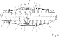
- Fig. 2 now shows a screw centrifuge according to the invention with an analogous representation to Fig. 1 was chosen. Same parts are denoted by the same reference numerals as in FIG Fig. 1 Mistake.
- additional parallel coil 13 ' This extension consists of one or more additional narrow (band) coil (s) 13 ', which (r) is arranged parallel to the coil 13 around the coil 23 (and 23') for the floating material 17 around. Due to the contrariness, there is a better separation of the solids.
- the coil 13,13 'are supported there are no separate supports required, which can constrict the helical turns of the screw and can lead to blockage / blocking of the machine.
- the worm spiral 23, 23 ' is designed to be double-threaded for the floating material 17, as a result of which a better delivery and thus a higher throughput can be achieved.
- feedstock often plastic mixtures of different densities are used, which are to be separated into swimming and Sinkgut-fractions. Depending on the application, the separation leads to a separation selectivity of well over 99% of the individual fractions.
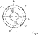
- Fig. 3 is a cut through Fig. 2 shown along the line III-III. It shows a section through the single helix.
- the screw 12 In the upper part of the section through the first coil 23 of the screw 12 for the separation of the floating material 17 is shown.
- the second coil 23 'for the floating In the lower part can be seen a section through the second coil 23 'for the floating.
- At the outer periphery of the coil 13 'for the debris 16 is shown.
- a catchy helix for the Sinkgut 16 occurs only the coil 13 'as shown in the upper part.
- Wendel 13 As shown in the lower part of the drawing, available.
- the invention is not limited by the examples in the drawings.
- the edges of the coils can also be protected by wear pieces from excessive wear.
- the invention relates to a screw centrifuge for wet-mechanical separation of solids by their density, having a rotating cylindrical drum with two conical drums connected thereto, with openings for the discharge of the separated substances as a sink and Weggut and the separating liquid, and a rotating shaft, with openings for the entry of the solids to be separated, wherein the shaft has two opposing worm helix, wherein in the axial direction between the entry opening for the substances to be separated and the discharge opening for the Sinkgut a baffle plate is arranged on the shaft.
- the outer spiral of the worm for the Sinkgut an overlap with the inner single or multi-start helix of the worm for the floating, wherein the helix are in opposite directions.
- the outer spiral of the worm for the debris can also be more smooth. As a result, a particularly high throughput can be achieved with a still high selective separation and a low residual moisture content.
- the invention also relates to a screw conveyor for such a screw centrifuge.
Landscapes
- Centrifugal Separators (AREA)
- Separation Of Solids By Using Liquids Or Pneumatic Power (AREA)
Abstract
Description
- Die Erfindung betrifft eine Schneckenzentrifuge zur nassmechanischen Trennung von Feststoffen nach ihrer Dichte mit einer rotierenden zylindrischen Trommel mit zwei konischen damit verbundenen Trommeln und Öffnungen für den Austrag der getrennten Stoffe als Sinkgut und Schwimmgut und der Trennflüssigkeit, und einer rotierenden Welle mit Öffnungen für den Eintrag der zu trennenden Feststoffe, wobei die Welle zwei gegenläufige Schneckenwendel aufweist, wobei in axialer Richtung zwischen der Eintragsöffnung für die zu trennenden Stoffe und der Austragsöffnung für das Sinkgut eine Stauscheibe auf der Welle angeordnet ist, wobei der außenliegende Wendel der Schnecke für das Sinkgut eine Überdeckung mit der innenliegenden Wendel der Schnecke für das Schwimmgut aufweist, wobei die Wendel gegenläufig sind.
- Derartige Schneckenzentrifugen sind z.B. aus der
EP 0 553 793 B1 bekannt. Derartige Maschinen sind im Durchsatz für das Leichtgut bzw. Schwimmgut begrenzt. Bei einer Steigerung des etablierten Durchsatzes verblockt die Maschine mit dem Produkt. Weitere ähnliche Maschinen sind aus derDE 195 16 636 A1 oder derEP 1485 205 B1 bekannt. Derartige Maschinen dienen zu einer 3 PhasenTrennung von Stoffgemischen, z.B. unterschiedliche Kunststofffraktionen und eine Trennflüssigkeit. Durch geeignete Wahl der Trennflüssigkeit in der Dichte können in mehrstufigen Verfahren auch mehrere unterschiedliche Fraktionen getrennt werden. Weiters beschreibt dieDE 3134935 A1 eine Dekanterzentrifuge zur Trennung von einer Feststoffphase und zwei Flüssigphasen. Eine Abtrennung von Leichtgut bzw. Schwimmgut ist hier nicht möglich. Auch die Dekantierzentrifuge derDE 2612696 ermöglicht keine Abtrennung von Schwimmgut. Sie trennt leichte und schwere Feststoffe, die sich absetzen bzw. durch die Schwerkraft an den Innenumfang der Zentrifugentrommel getragen werden. DieUS 2528974 beschreibt einen Zentrifugalseparator zur Trennung von Feststoff und Flüssigkeit, womit ebenfalls keine Dreiphasen Trennung möglich ist. Der Spiralseparator derUS4781822 trennt zwei Sorten von Partikeln entsprechend der Dichte bzw. der Größe. - Ziel der Erfindung ist es daher eine bessere Trennung und höhere Durchsatzleistung bei einer Dreiphasen Trennung zu erreichen.
- Die Erfindung ist daher dadurch gekennzeichnet, dass die Schnecke für das Schwimmgut als mehrgängige Schnecke ausgeführt ist. Damit kann der Durchsatz bei gleicher Trennqualität und Produktrestfeuchte stark erhöht werden, wobei auch eine deutliche Reduktion von Verstopfung/Verblockung der Maschine trotz höherer Durchsätze erreicht wird.
- Eine günstige Ausgestaltung der Erfindung ist dadurch gekennzeichnet, dass der Schneckenwendel für das Sinkgut bis zur Trommel reicht und der Schneckenwendel für das Schwimmgut einen kleineren Außendurchmesser aufweist als der Innendurchmesser des Schneckenwendel der Schnecke für das Sinkgut. Durch diese Maßnahme und die Gegenläufigkeit der beiden Schnecken kann das Leichtgut, das auf der Trennflüssigkeit aufschwimmt, von dem inneren Wendel zum Leichtgutaustrag transportiert werden, während das Schwergut absinkt, sich an der Trommelwand sammelt und von dem äußeren Wendel zum gegenüberliegenden Austrag transportiert wird. Die Trennflüssigkeit wird hierbei gesondert über Düsen abgeschieden.
- Eine günstige Weiterbildung der Erfindung ist dadurch gekennzeichnet, dass der Teil der Überdeckung der Schneckenwendel für das Sinkgut direkt mit dem Wendel für das Schwimmgut verbunden, vorzugsweise verschweißt, ist. Damit werden keinerlei zusätzliche Stützen erforderlich, die die Wege des separierten Gutes beeinträchtigen könnten.
- Eine vorteilhafte Weiterbildung der Erfindung ist dadurch gekennzeichnet, dass die Schnecke für das Sinkgut als mehrgängige Schnecke ausgeführt ist. Bei einer geeigneten Wahl von Gängen und Steigung kann die Gesamtkapazität einer Schnecke gesteigert werden.
- Die vom jeweiligen Wendelgang geförderte Produktmenge (das Produkt-"Haufwerk" vor dem Wendel) ist im Vergleich zum eingängigen Wendel deutlich reduziert. Dies unterstützt die Stabilität des Prozesses, die Trennung der Produktfraktionen, den Transport derjeweiligen Fraktion und die Abtrennung vom Trennmedium bei deutlich erhöhten Produktdurchsätzen.
- Die Erfindung wird nun im Folgenden anhand der Zeichnungen beispielhaft beschrieben, wobei
-
Fig. 1 eine Schneckenzentrifuge nach dem Stand der Technik -
Fig. 2 eine Schneckenzentrifuge nach der Erfindung -
Fig. 3 einen Schnitt durchFig. 2 entlang Linie III-III - In
Fig. 1 besteht die Trennvorrichtung 10 aus einer zylindrischen an beiden Enden konischen Trommel 11. Innerhalb der Trommel 11 befindet sich eine zweiteilige Transportschnecke 12 mit Schneckenwendeln 13 zum Austrag des Sinkgutes 16 und mit Schneckenwendeln 23 zum Austrag des Schwimmgutes 17. Durch unterschiedliche Gestaltung der Schneckenwendeln, z.B. äußerer Durchmesser, gegenläufige Wendeln, werden das Sinkgut 16 und das Schwimmgut 17 zu entgegengesetzt angeordneten Austragsöffnungen 14, 15 transportiert: das Sinkgut 16 zu einer oder mehreren Austragsöffnungen 14, das Schwimmgut 17 zu einer oder mehreren Austragsöffnungen 15. Die vom Sinkgut und vom Schwimmgut abgetrennte Trennflüssigkeit 18 wird über eine oder mehrere Düsen 19 auf der Schwergutseite der Trennvorrichtung 10 ausgetragen. Eine Stauscheibe 20 verhindert, dass während des Trennvorgangs das Schwimmgut 17 von den Wendeln 13 für das Sinkgut 16 mit erfasst werden kann und zum Sinkgutaustrag 14 gelangt. Das zu trennende Gemisch aus Feststoffen und Trennflüssigkeit wird über ein axial angeordnetes Aufgaberohr 21 durch eine oder mehrere Aufgabeöffnungen 22 in den Behälterinnenraum aufgegeben. Durch Rotation der Trommel 11 und der Transportschnecke 12 wird das Gemisch, beispielsweise Suspension, in Rotation versetzt und in der Suspension ein Zentrifugalfeld erzeugt. Die Transportschnecke 12 wird dabei üblicherweise mit einer von der Trommeldrehzahl abweichenden Drehzahl angetrieben. Infolge des Dichteunterschieds der Feststoffe und der Trennflüssigkeit findet in kurzer Zeit eine Trennung der Feststoffe statt, wobei der leichte Feststoff (Schwimmgut 17) sich an der Oberfläche der Trennflüssigkeit 18 anordnet und der schwere Feststoff (Sinkgut 16) zur inneren Mantelfläche der Trommel 11 absinkt. Das Schwimmgut wird nun von dem Schneckenwendel 23 erfasst und zur Austragsöffnung 15 gefördert, das Sinkgut 16 wird durch den Schneckenwendel 13 erfasst, zur Austragsöffnung 14 gefördert und infolge des konischen Verlaufes der Mantelfläche der Trommel 11 aus der Trennflüssigkeit herausgehoben und über die Austragsöffnung 14 aus der Trommel 11 herausgefördert. Der konische Teil der Trommel 11 im Bereich der Austragsöffnung 15 erleichtert die Abscheidung des Schwimmgutes 17 von der Trennflüssigkeit 18. -
Fig. 2 zeigt nun eine Schneckenzentrifuge nach der Erfindung wobei eine analoge Darstellung zuFig. 1 gewählt wurde. Gleiche Teile sind mit den gleichen Bezugszeichen wie inFig. 1 versehen. Um eine Verbesserung im Durchsatz bei gleicher Trennselektivität und Restfeuchte zu erlangen, wird der Transport des Sinkgutes 16 über Wendel 13 zur Austragsöffnung 14 um zusätzliche Parallel-Wendel 13' ergänzt. Diese Erweiterung besteht aus einem oder mehreren zusätzlichen schmalen (Band-) Wendel(n) 13', welche(r) parallel zur Wendel 13 um den Wendel 23 (und 23') für das Schwimmgut 17 herum angeordnet ist. Durch die Gegenläufigkeit erfolgt eine bessere Trennung der Feststoffe. Die Wendel(n) 13,13' wird bzw. werden dabei an verschiedenen Punkten mit den Wendeln 23, 23' verbunden, beispielsweise verschweißt. Dadurch sind die Wendel 13,13' abgestützt, es sind keine separaten Stützen erforderlich, die die Wendelgänge der Schnecke einengen können und zu Verstopfung/Verblockung der Maschine führen können. Erfindungsgemäß ist der Schneckenwendel 23, 23' für das Schwimmgut 17 zweigängig ausgeführt, wodurch eine bessere Förderung und damit ein höherer Durchsatz erzielt werden können. Als zu verarbeitendes Produkt (Aufgabegut) werden häufig Kunststoffgemische von unterschiedlicher Dichte eingesetzt, die in Schwimm- und Sinkgut-fraktionen aufgetrennt werden sollen. Die Auftrennung führt je nach Anwendung zu einer Trennselektivität von deutlich über 99% der einzelnen Fraktionen. So können neben stückigen Kunststoffgemischen oder-folien auch Fasermaterialien wie z.B. Teppichreste u.a. aus Polypropylen, Polyamid und Latex in einem zweistufigen Verfahren aufgetrennt und somit einer Wiederverwertung zugeführt werden. Auch werden die getrennten Feststoffe während des Trennprozesses vor ihrem Austrag zu gewissem Grad einer Waschung unterzogen. Für eine noch effektivere Trennung können die beide Schneckenwendelgruppen für Sink- und Schwimmgut je nach Bedarfsfall auch mit für den Prozess notwendigen unterschiedlichen Steigungen installiert werden, wodurch sich die Maschine perfekt auf den Prozess abstimmen lässt. - In
Fig. 3 ist ein Schnitt durchFig. 2 entlang der Linie III-III dargestellt. Sie zeigt dabei einen Schnitt durch die einzelnen Schneckenwendel. Im oberen Teil ist der Schnitt durch den ersten Wendel 23 der Schnecke 12 zur Abtrennung des Schwimmgutes 17 dargestellt. Im unteren Teil erkennt man einen Schnitt durch den zweiten Wendel 23' für das Schwimmgut. Es können aber auch noch weitere Schneckenwendel eingesetzt werden, so dass die Schnecke dann gegebenenfalls auch drei oder mehr Schneckengänge aufweist. Am äußeren Umfang ist der Wendel 13' für das Sinkgut 16 dargestellt. Bei einem eingängigen Wendel für das Sinkgut 16 tritt nur der Wendel 13' wie im oberen Teil dargestellt auf. Bei einem zweigängigen Wendel ist auch noch Wendel 13" wie im unteren Teil der Zeichnung gezeigt, vorhanden. - Die Erfindung ist nicht durch die Beispiele in den Zeichnungen beschränkt. Die Kanten der Wendeln können auch durch Verschleißstücke vor zu starkem Verschleiß geschützt werden.
- Zusammenfassend ist festzuhalten, dass die Erfindung eine Schneckenzentrifuge zur nassmechanischen Trennung von Feststoffen nach ihrer Dichte betrifft, die eine rotierende zylindrische Trommel mit zwei konischen damit verbundenen Trommeln aufweist, mit Öffnungen für den Austrag der getrennten Stoffe als Sinkgut und Schwimmgut und der Trennflüssigkeit, und einer rotierenden Welle, mit Öffnungen für den Eintrag der zu trennenden Feststoffe, wobei die Welle zwei gegenläufige Schneckenwendel aufweist, wobei in axialer Richtung zwischen der Eintragsöffnung für die zu trennenden Stoffe und der Austragsöffnung für das Sinkgut eine Stauscheibe auf der Welle angeordnet ist. Außerdem weist der außenliegende Wendel der Schnecke für das Sinkgut eine Überdeckung mit dem innenliegenden ein- oder mehrgängigen Wendel der Schnecke für das Schwimmgut auf, wobei die Wendel gegenläufig sind. Der außenliegende Wendel der Schnecke für das Sinkgut kann auch mehrgängig sein. Dadurch lässt sich ein besonders hoher Durchsatz bei weiterhin hoher selektiver Trennung und gleich niedriger Restfeuchte erreichen. Die Erfindung betrifft auch eine Transportschnecke für eine derartige Schneckenzentrifuge.
Claims (6)
- Schneckenzentrifuge zur nassmechanischen Trennung von Feststoffen nach ihrer Dichte mit einer rotierenden zylindrischen Trommel (11) mit zwei konischen damit verbundenen Trommeln, mit Öffnungen (14, 15) für den Austrag der getrennten Stoffe als Sinkgut (16) und Schwimmgut (17) und der Trennflüssigkeit (18), und einer rotierenden Welle (12) mit Öffnungen (22) für den Eintrag der zu trennenden Feststoffe, wobei die Welle (12) zwei gegenläufige Schneckenwendel (13, 13', 13", 23, 23') aufweist, wobei in axialer Richtung zwischen der Eintragsöffnung (22) für die zu trennenden Stoffe und der Austragsöffnung (14) für das Sinkgut (16) eine Stauscheibe (20) auf der Welle angeordnet ist, wobei der außenliegende Wendel (13', 13") der Schnecke für das Sinkgut (16) eine Überdeckung mit dem innenliegenden Wendel (23, 23') der Schnecke für das Schwimmgut (17) aufweist, wobei die Wendel (13, 13', 13", 23, 23') gegenläufig sind, dadurch gekennzeichnet, dass die Schnecke für das Schwimmgut (17) als mehrgängige Schnecke ausgeführt ist.
- Schneckenzentrifuge nach Anspruch 1, dadurch gekennzeichnet, dass der Schneckenwendel (13, 13', 13") für das Sinkgut (16) bis zur Trommel (11) reicht und der Schneckenwendel (23, 23') für das Schwimmgut (17) einen kleineren Außendurchmesser aufweist als der Innendurchmesser des Schneckenwendel (13', 13") der Schnecke für das Sinkgut (16).
- Schneckenzentrifuge nach Anspruch 1 oder 2, dadurch gekennzeichnet, dass der Teil der Überdeckung des Schneckenwendel (13', 13") für das Sinkgut (16) direkt mit dem Schneckenwendel (23, 23') für das Schwimmgut (17) verbunden, vorzugsweise verschweißt, ist.
- Schneckenzentrifuge nach einem der Ansprüche 1 bis 3, dadurch gekennzeichnet, dass die Schnecke für das Sinkgut (16) als mehrgängige Schnecke ausgeführt ist.
- Transportschnecke für eine Schneckenzentrifuge nach einem der Ansprüche 1 bis 4, dadurch gekennzeichnet, dass die Welle (12) zwei gegenläufige Schneckenwendel (13, 13', 13", 23, 23') aufweist, wobei der außenliegende Wendel (13', 13") der Schnecke für das Sinkgut (16) eine Überdeckung mit der innenliegenden Wendel (23, 23') der Schnecke für das Schwimmgut (17) aufweist, wobei die Wendel (13, 13', 13", 23, 23') gegenläufig sind und die Schnecke für das Schwimmgut (17) als mehrgängige Schnecke ausgeführt ist.
- Transportschnecke nach Anspruch 5, dadurch gekennzeichnet, dass die Schnecke für das Sinkgut (16) als mehrgängige Schnecke ausgeführt ist.
Applications Claiming Priority (1)
| Application Number | Priority Date | Filing Date | Title |
|---|---|---|---|
| ATA50367/2016A AT518275B1 (de) | 2016-04-26 | 2016-04-26 | Schneckenzentrifuge zur nassmechanischen trennung von feststoffen |
Publications (3)
| Publication Number | Publication Date |
|---|---|
| EP3238828A1 true EP3238828A1 (de) | 2017-11-01 |
| EP3238828B1 EP3238828B1 (de) | 2025-01-08 |
| EP3238828C0 EP3238828C0 (de) | 2025-01-08 |
Family
ID=58261596
Family Applications (1)
| Application Number | Title | Priority Date | Filing Date |
|---|---|---|---|
| EP17159643.0A Active EP3238828B1 (de) | 2016-04-26 | 2017-03-07 | Schneckenzentrifuge zur nassmechanischen trennung von feststoffen |
Country Status (5)
| Country | Link |
|---|---|
| US (1) | US10213791B2 (de) |
| EP (1) | EP3238828B1 (de) |
| JP (1) | JP6840011B2 (de) |
| AT (1) | AT518275B1 (de) |
| CA (1) | CA2963405C (de) |
Families Citing this family (4)
| Publication number | Priority date | Publication date | Assignee | Title |
|---|---|---|---|---|
| AT518275B1 (de) | 2016-04-26 | 2017-09-15 | Andritz Tech And Asset Man Gmbh | Schneckenzentrifuge zur nassmechanischen trennung von feststoffen |
| CN110935553B (zh) * | 2019-11-29 | 2025-07-08 | 云南焠金时代科技有限公司 | 一种圆环形盘式选矿机及选矿方法 |
| AU2022370909A1 (en) * | 2021-10-22 | 2024-06-06 | Thomas A. Valerio | Method and system for waste separation using a multi-spiral separator |
| DE102021133336A1 (de) * | 2021-12-15 | 2023-06-15 | Gea Westfalia Separator Group Gmbh | Separator und Verfahren zum Klären eines Flüssigkeits-/Feststoffgemischs |
Citations (3)
| Publication number | Priority date | Publication date | Assignee | Title |
|---|---|---|---|---|
| US2528974A (en) * | 1945-09-19 | 1950-11-07 | Process Dev Company | Method and apparatus for centrifugal separation |
| EP0553793A2 (de) * | 1992-01-31 | 1993-08-04 | Klöckner-Humboldt-Deutz Aktiengesellschaft | Vorrichtung und Verfahren zur nassmechanischen Aufbereitung von Feststoffen |
| EP1020227A1 (de) * | 1999-01-18 | 2000-07-19 | Baker Hughes (Deutschland) GmbH | Zentrifuge zur nassmechanischen Trennung von Feststoffgemischen |
Family Cites Families (9)
| Publication number | Priority date | Publication date | Assignee | Title |
|---|---|---|---|---|
| US2919848A (en) * | 1956-03-14 | 1960-01-05 | Andrew F Howe | Centrifugal separation |
| DE2612696A1 (de) * | 1975-04-01 | 1976-10-14 | Pennwalt Corp | Vollmantel-dekantierzentrifuge |
| DE3134935A1 (de) * | 1980-09-09 | 1982-06-09 | Alfa-Laval Separation A/S, 2860 Soeborg | "mitstrom-dekanterzentrifuge" |
| US4781822A (en) * | 1985-08-08 | 1988-11-01 | Minpro Pty. Limited | Spiral separator |
| DE4222119C2 (de) * | 1992-07-06 | 1997-07-10 | Deutz Ag | Vorrichtung und Verfahren zur naßmechanischen Trennung von Feststoffgemischen |
| DE4305346A1 (de) * | 1993-02-20 | 1994-08-25 | Kloeckner Humboldt Deutz Ag | Vorrichtung und Verfahren zur naßmechanischen Aufbereitung von Feststoffen |
| JP2002186878A (ja) * | 2000-12-21 | 2002-07-02 | Nkk Corp | 湿式比重分離装置およびその運転方法 |
| DE10212187A1 (de) * | 2002-03-20 | 2003-10-02 | Hiller Gmbh | Schneckenzentrifuge |
| AT518275B1 (de) | 2016-04-26 | 2017-09-15 | Andritz Tech And Asset Man Gmbh | Schneckenzentrifuge zur nassmechanischen trennung von feststoffen |
-
2016
- 2016-04-26 AT ATA50367/2016A patent/AT518275B1/de active
-
2017
- 2017-03-07 EP EP17159643.0A patent/EP3238828B1/de active Active
- 2017-03-30 JP JP2017067514A patent/JP6840011B2/ja active Active
- 2017-04-05 CA CA2963405A patent/CA2963405C/en active Active
- 2017-04-24 US US15/494,853 patent/US10213791B2/en active Active
Patent Citations (3)
| Publication number | Priority date | Publication date | Assignee | Title |
|---|---|---|---|---|
| US2528974A (en) * | 1945-09-19 | 1950-11-07 | Process Dev Company | Method and apparatus for centrifugal separation |
| EP0553793A2 (de) * | 1992-01-31 | 1993-08-04 | Klöckner-Humboldt-Deutz Aktiengesellschaft | Vorrichtung und Verfahren zur nassmechanischen Aufbereitung von Feststoffen |
| EP1020227A1 (de) * | 1999-01-18 | 2000-07-19 | Baker Hughes (Deutschland) GmbH | Zentrifuge zur nassmechanischen Trennung von Feststoffgemischen |
Also Published As
| Publication number | Publication date |
|---|---|
| CA2963405C (en) | 2022-04-26 |
| AT518275B1 (de) | 2017-09-15 |
| JP2017196615A (ja) | 2017-11-02 |
| EP3238828B1 (de) | 2025-01-08 |
| AT518275A4 (de) | 2017-09-15 |
| US10213791B2 (en) | 2019-02-26 |
| JP6840011B2 (ja) | 2021-03-10 |
| CA2963405A1 (en) | 2017-10-26 |
| US20170304846A1 (en) | 2017-10-26 |
| EP3238828C0 (de) | 2025-01-08 |
Similar Documents
| Publication | Publication Date | Title |
|---|---|---|
| DE3318793A1 (de) | Vorrichtung zum entfeuchten von schlamm | |
| AT518275B1 (de) | Schneckenzentrifuge zur nassmechanischen trennung von feststoffen | |
| EP0553793B1 (de) | Vorrichtung und Verfahren zur nassmechanischen Aufbereitung von Feststoffen | |
| DE102019102623A1 (de) | Verfahren zum Klären einer Suspension von Feststoffen | |
| EP1468744A1 (de) | Schubzentrifuge mit rotierbarem Trichter zur Vorbeschleunigung des Gemisches | |
| WO2003078070A1 (de) | Schneckenzentrifuge | |
| DE4115347C2 (de) | Vollmantel-Schneckenzentrifuge zur Klassierung eines Feststoff-Flüssigkeitsgemisches | |
| DE3301099C2 (de) | ||
| DE19516636C2 (de) | Vollmantel-Schnecken-Zentrifuge zur naßmechanischen Trennung von Feststoffen | |
| DE102019000604A1 (de) | Verfahren und Vorrichtung zur flüssigkeitsarmen mechanischen Rohmaterialbeschickung von Durchlauftrennzentrifugen oder anderen Rotationsmaschinen und deren möglicher Entschickung über Siebmäntel oder einfachem Naßaustrag | |
| WO2007074076A1 (de) | Vollmantel-schneckenzentrifuge | |
| DE2718673A1 (de) | Verfahren und vorrichtung zum entwaessern von schlamm | |
| EP0421188B1 (de) | Schubzentrifuge | |
| WO2011117090A1 (de) | Vollmantel-schneckenzentrifuge | |
| EP0076476A2 (de) | Dekantier-Zentrifuge | |
| EP0631820B1 (de) | Verfahren zum Betrieb von Schneckenzentrifugen | |
| DE3132740A1 (de) | Vollmantelzentrifuge mit siebteil | |
| DE1757368C3 (de) | Vollmantel-Schneckenzentrifuge | |
| EP1260273A1 (de) | Vollmantel-Schneckenzentrifuge | |
| WO2008064905A1 (de) | Verfahren zur zentrifugalen klärung eines ölhaltigen sandes | |
| DE3335873A1 (de) | Vollmantel-schneckenzentrifuge zur trennung eines feststoff-fluessigkeitsgemisches | |
| DE19901655A1 (de) | Zentrifuge zur naßmechanischen Trennung von Feststoffgemischen | |
| EP1468742A1 (de) | Mehrstufige Schubzentrifuge | |
| DE2637968A1 (de) | Dekantierzentrifuge | |
| EP1468743A1 (de) | Schubzentrifuge |
Legal Events
| Date | Code | Title | Description |
|---|---|---|---|
| PUAI | Public reference made under article 153(3) epc to a published international application that has entered the european phase |
Free format text: ORIGINAL CODE: 0009012 |
|
| STAA | Information on the status of an ep patent application or granted ep patent |
Free format text: STATUS: THE APPLICATION HAS BEEN PUBLISHED |
|
| AK | Designated contracting states |
Kind code of ref document: A1 Designated state(s): AL AT BE BG CH CY CZ DE DK EE ES FI FR GB GR HR HU IE IS IT LI LT LU LV MC MK MT NL NO PL PT RO RS SE SI SK SM TR |
|
| AX | Request for extension of the european patent |
Extension state: BA ME |
|
| STAA | Information on the status of an ep patent application or granted ep patent |
Free format text: STATUS: REQUEST FOR EXAMINATION WAS MADE |
|
| 17P | Request for examination filed |
Effective date: 20180404 |
|
| RBV | Designated contracting states (corrected) |
Designated state(s): AL AT BE BG CH CY CZ DE DK EE ES FI FR GB GR HR HU IE IS IT LI LT LU LV MC MK MT NL NO PL PT RO RS SE SI SK SM TR |
|
| STAA | Information on the status of an ep patent application or granted ep patent |
Free format text: STATUS: EXAMINATION IS IN PROGRESS |
|
| 17Q | First examination report despatched |
Effective date: 20201207 |
|
| GRAP | Despatch of communication of intention to grant a patent |
Free format text: ORIGINAL CODE: EPIDOSNIGR1 |
|
| STAA | Information on the status of an ep patent application or granted ep patent |
Free format text: STATUS: GRANT OF PATENT IS INTENDED |
|
| INTG | Intention to grant announced |
Effective date: 20240927 |
|
| GRAS | Grant fee paid |
Free format text: ORIGINAL CODE: EPIDOSNIGR3 |
|
| GRAA | (expected) grant |
Free format text: ORIGINAL CODE: 0009210 |
|
| STAA | Information on the status of an ep patent application or granted ep patent |
Free format text: STATUS: THE PATENT HAS BEEN GRANTED |
|
| AK | Designated contracting states |
Kind code of ref document: B1 Designated state(s): AL AT BE BG CH CY CZ DE DK EE ES FI FR GB GR HR HU IE IS IT LI LT LU LV MC MK MT NL NO PL PT RO RS SE SI SK SM TR |
|
| REG | Reference to a national code |
Ref country code: GB Ref legal event code: FG4D Free format text: NOT ENGLISH |
|
| REG | Reference to a national code |
Ref country code: CH Ref legal event code: EP |
|
| REG | Reference to a national code |
Ref country code: DE Ref legal event code: R096 Ref document number: 502017016643 Country of ref document: DE |
|
| REG | Reference to a national code |
Ref country code: IE Ref legal event code: FG4D Free format text: LANGUAGE OF EP DOCUMENT: GERMAN |
|
| U01 | Request for unitary effect filed |
Effective date: 20250116 |
|
| U07 | Unitary effect registered |
Designated state(s): AT BE BG DE DK EE FI FR IT LT LU LV MT NL PT RO SE SI Effective date: 20250122 |
|
| U20 | Renewal fee for the european patent with unitary effect paid |
Year of fee payment: 9 Effective date: 20250325 |
|
| PG25 | Lapsed in a contracting state [announced via postgrant information from national office to epo] |
Ref country code: RS Free format text: LAPSE BECAUSE OF FAILURE TO SUBMIT A TRANSLATION OF THE DESCRIPTION OR TO PAY THE FEE WITHIN THE PRESCRIBED TIME-LIMIT Effective date: 20250408 |
|
| PG25 | Lapsed in a contracting state [announced via postgrant information from national office to epo] |
Ref country code: PL Free format text: LAPSE BECAUSE OF FAILURE TO SUBMIT A TRANSLATION OF THE DESCRIPTION OR TO PAY THE FEE WITHIN THE PRESCRIBED TIME-LIMIT Effective date: 20250108 |
|
| PG25 | Lapsed in a contracting state [announced via postgrant information from national office to epo] |
Ref country code: ES Free format text: LAPSE BECAUSE OF FAILURE TO SUBMIT A TRANSLATION OF THE DESCRIPTION OR TO PAY THE FEE WITHIN THE PRESCRIBED TIME-LIMIT Effective date: 20250108 |
|
| PG25 | Lapsed in a contracting state [announced via postgrant information from national office to epo] |
Ref country code: NO Free format text: LAPSE BECAUSE OF FAILURE TO SUBMIT A TRANSLATION OF THE DESCRIPTION OR TO PAY THE FEE WITHIN THE PRESCRIBED TIME-LIMIT Effective date: 20250408 Ref country code: IS Free format text: LAPSE BECAUSE OF FAILURE TO SUBMIT A TRANSLATION OF THE DESCRIPTION OR TO PAY THE FEE WITHIN THE PRESCRIBED TIME-LIMIT Effective date: 20250508 |
|
| PG25 | Lapsed in a contracting state [announced via postgrant information from national office to epo] |
Ref country code: HR Free format text: LAPSE BECAUSE OF FAILURE TO SUBMIT A TRANSLATION OF THE DESCRIPTION OR TO PAY THE FEE WITHIN THE PRESCRIBED TIME-LIMIT Effective date: 20250108 |
|
| PG25 | Lapsed in a contracting state [announced via postgrant information from national office to epo] |
Ref country code: GR Free format text: LAPSE BECAUSE OF FAILURE TO SUBMIT A TRANSLATION OF THE DESCRIPTION OR TO PAY THE FEE WITHIN THE PRESCRIBED TIME-LIMIT Effective date: 20250409 |
|
| PG25 | Lapsed in a contracting state [announced via postgrant information from national office to epo] |
Ref country code: SM Free format text: LAPSE BECAUSE OF FAILURE TO SUBMIT A TRANSLATION OF THE DESCRIPTION OR TO PAY THE FEE WITHIN THE PRESCRIBED TIME-LIMIT Effective date: 20250108 |
|
| PG25 | Lapsed in a contracting state [announced via postgrant information from national office to epo] |
Ref country code: MC Free format text: LAPSE BECAUSE OF FAILURE TO SUBMIT A TRANSLATION OF THE DESCRIPTION OR TO PAY THE FEE WITHIN THE PRESCRIBED TIME-LIMIT Effective date: 20250108 |
|
| PG25 | Lapsed in a contracting state [announced via postgrant information from national office to epo] |
Ref country code: CZ Free format text: LAPSE BECAUSE OF FAILURE TO SUBMIT A TRANSLATION OF THE DESCRIPTION OR TO PAY THE FEE WITHIN THE PRESCRIBED TIME-LIMIT Effective date: 20250108 |
|
| REG | Reference to a national code |
Ref country code: CH Ref legal event code: H13 Free format text: ST27 STATUS EVENT CODE: U-0-0-H10-H13 (AS PROVIDED BY THE NATIONAL OFFICE) Effective date: 20251023 |
|
| PG25 | Lapsed in a contracting state [announced via postgrant information from national office to epo] |
Ref country code: SK Free format text: LAPSE BECAUSE OF FAILURE TO SUBMIT A TRANSLATION OF THE DESCRIPTION OR TO PAY THE FEE WITHIN THE PRESCRIBED TIME-LIMIT Effective date: 20250108 |
|
| PLBE | No opposition filed within time limit |
Free format text: ORIGINAL CODE: 0009261 |
|
| STAA | Information on the status of an ep patent application or granted ep patent |
Free format text: STATUS: NO OPPOSITION FILED WITHIN TIME LIMIT |
|
| 26N | No opposition filed |
Effective date: 20251009 |
|
| PG25 | Lapsed in a contracting state [announced via postgrant information from national office to epo] |
Ref country code: CH Free format text: LAPSE BECAUSE OF NON-PAYMENT OF DUE FEES Effective date: 20250331 |
|
| PG25 | Lapsed in a contracting state [announced via postgrant information from national office to epo] |
Ref country code: IE Free format text: LAPSE BECAUSE OF NON-PAYMENT OF DUE FEES Effective date: 20250307 |
|
| PGFP | Annual fee paid to national office [announced via postgrant information from national office to epo] |
Ref country code: GB Payment date: 20260324 Year of fee payment: 10 |
|
| U20 | Renewal fee for the european patent with unitary effect paid |
Year of fee payment: 10 Effective date: 20260326 |
|
| PG25 | Lapsed in a contracting state [announced via postgrant information from national office to epo] |
Ref country code: CY Free format text: LAPSE BECAUSE OF FAILURE TO SUBMIT A TRANSLATION OF THE DESCRIPTION OR TO PAY THE FEE WITHIN THE PRESCRIBED TIME-LIMIT Effective date: 20250108 |
|
| PG25 | Lapsed in a contracting state [announced via postgrant information from national office to epo] |
Ref country code: TR Free format text: LAPSE BECAUSE OF FAILURE TO SUBMIT A TRANSLATION OF THE DESCRIPTION OR TO PAY THE FEE WITHIN THE PRESCRIBED TIME-LIMIT Effective date: 20250108 |