EP3238596B1 - Floor cleaner, cleaning roller component, and sponge roller - Google Patents
Floor cleaner, cleaning roller component, and sponge roller Download PDFInfo
- Publication number
- EP3238596B1 EP3238596B1 EP15905699.3A EP15905699A EP3238596B1 EP 3238596 B1 EP3238596 B1 EP 3238596B1 EP 15905699 A EP15905699 A EP 15905699A EP 3238596 B1 EP3238596 B1 EP 3238596B1
- Authority
- EP
- European Patent Office
- Prior art keywords
- sponge roller
- sponge
- water
- inner layer
- outer layer
- Prior art date
- Legal status (The legal status is an assumption and is not a legal conclusion. Google has not performed a legal analysis and makes no representation as to the accuracy of the status listed.)
- Active
Links
- 238000004140 cleaning Methods 0.000 title claims description 49
- XLYOFNOQVPJJNP-UHFFFAOYSA-N water Substances O XLYOFNOQVPJJNP-UHFFFAOYSA-N 0.000 claims description 61
- 239000002351 wastewater Substances 0.000 claims description 55
- 230000002745 absorbent Effects 0.000 claims description 25
- 239000002250 absorbent Substances 0.000 claims description 25
- 239000010813 municipal solid waste Substances 0.000 description 18
- 238000010586 diagram Methods 0.000 description 11
- 230000007246 mechanism Effects 0.000 description 10
- 230000006872 improvement Effects 0.000 description 6
- 238000005406 washing Methods 0.000 description 6
- 238000000605 extraction Methods 0.000 description 5
- 230000000694 effects Effects 0.000 description 4
- 239000007788 liquid Substances 0.000 description 4
- 238000007599 discharging Methods 0.000 description 3
- 238000005265 energy consumption Methods 0.000 description 3
- 239000006260 foam Substances 0.000 description 3
- 230000003993 interaction Effects 0.000 description 3
- 238000011084 recovery Methods 0.000 description 3
- 239000002699 waste material Substances 0.000 description 3
- 230000009471 action Effects 0.000 description 2
- 230000002349 favourable effect Effects 0.000 description 2
- 239000000463 material Substances 0.000 description 2
- 230000004048 modification Effects 0.000 description 2
- 238000012986 modification Methods 0.000 description 2
- 238000007789 sealing Methods 0.000 description 2
- 244000007853 Sarothamnus scoparius Species 0.000 description 1
- 230000004308 accommodation Effects 0.000 description 1
- 230000003247 decreasing effect Effects 0.000 description 1
- 239000000428 dust Substances 0.000 description 1
- 239000013013 elastic material Substances 0.000 description 1
- 238000005516 engineering process Methods 0.000 description 1
- 239000002184 metal Substances 0.000 description 1
- 238000005086 pumping Methods 0.000 description 1
- 238000005096 rolling process Methods 0.000 description 1
- 239000002910 solid waste Substances 0.000 description 1
- 230000001960 triggered effect Effects 0.000 description 1
Images


Classifications
-
- A—HUMAN NECESSITIES
- A47—FURNITURE; DOMESTIC ARTICLES OR APPLIANCES; COFFEE MILLS; SPICE MILLS; SUCTION CLEANERS IN GENERAL
- A47L—DOMESTIC WASHING OR CLEANING; SUCTION CLEANERS IN GENERAL
- A47L13/00—Implements for cleaning floors, carpets, furniture, walls, or wall coverings
- A47L13/10—Scrubbing; Scouring; Cleaning; Polishing
- A47L13/14—Scrubbing; Scouring; Cleaning; Polishing combined with squeezing or wringing devices
- A47L13/144—Scrubbing; Scouring; Cleaning; Polishing combined with squeezing or wringing devices having squeezing rollers
-
- A—HUMAN NECESSITIES
- A47—FURNITURE; DOMESTIC ARTICLES OR APPLIANCES; COFFEE MILLS; SPICE MILLS; SUCTION CLEANERS IN GENERAL
- A47L—DOMESTIC WASHING OR CLEANING; SUCTION CLEANERS IN GENERAL
- A47L11/00—Machines for cleaning floors, carpets, furniture, walls, or wall coverings
- A47L11/26—Floor-scrubbing machines, hand-driven
-
- A—HUMAN NECESSITIES
- A47—FURNITURE; DOMESTIC ARTICLES OR APPLIANCES; COFFEE MILLS; SPICE MILLS; SUCTION CLEANERS IN GENERAL
- A47L—DOMESTIC WASHING OR CLEANING; SUCTION CLEANERS IN GENERAL
- A47L11/00—Machines for cleaning floors, carpets, furniture, walls, or wall coverings
- A47L11/28—Floor-scrubbing machines, motor-driven
- A47L11/282—Floor-scrubbing machines, motor-driven having rotary tools
-
- A—HUMAN NECESSITIES
- A47—FURNITURE; DOMESTIC ARTICLES OR APPLIANCES; COFFEE MILLS; SPICE MILLS; SUCTION CLEANERS IN GENERAL
- A47L—DOMESTIC WASHING OR CLEANING; SUCTION CLEANERS IN GENERAL
- A47L11/00—Machines for cleaning floors, carpets, furniture, walls, or wall coverings
- A47L11/40—Parts or details of machines not provided for in groups A47L11/02 - A47L11/38, or not restricted to one of these groups, e.g. handles, arrangements of switches, skirts, buffers, levers
- A47L11/4013—Contaminants collecting devices, i.e. hoppers, tanks or the like
- A47L11/4016—Contaminants collecting devices, i.e. hoppers, tanks or the like specially adapted for collecting fluids
- A47L11/4019—Fill level sensors; Security means to prevent overflow, e.g. float valves
-
- A—HUMAN NECESSITIES
- A47—FURNITURE; DOMESTIC ARTICLES OR APPLIANCES; COFFEE MILLS; SPICE MILLS; SUCTION CLEANERS IN GENERAL
- A47L—DOMESTIC WASHING OR CLEANING; SUCTION CLEANERS IN GENERAL
- A47L11/00—Machines for cleaning floors, carpets, furniture, walls, or wall coverings
- A47L11/40—Parts or details of machines not provided for in groups A47L11/02 - A47L11/38, or not restricted to one of these groups, e.g. handles, arrangements of switches, skirts, buffers, levers
- A47L11/4036—Parts or details of the surface treating tools
- A47L11/4041—Roll shaped surface treating tools
-
- A—HUMAN NECESSITIES
- A47—FURNITURE; DOMESTIC ARTICLES OR APPLIANCES; COFFEE MILLS; SPICE MILLS; SUCTION CLEANERS IN GENERAL
- A47L—DOMESTIC WASHING OR CLEANING; SUCTION CLEANERS IN GENERAL
- A47L11/00—Machines for cleaning floors, carpets, furniture, walls, or wall coverings
- A47L11/40—Parts or details of machines not provided for in groups A47L11/02 - A47L11/38, or not restricted to one of these groups, e.g. handles, arrangements of switches, skirts, buffers, levers
- A47L11/408—Means for supplying cleaning or surface treating agents
-
- A—HUMAN NECESSITIES
- A47—FURNITURE; DOMESTIC ARTICLES OR APPLIANCES; COFFEE MILLS; SPICE MILLS; SUCTION CLEANERS IN GENERAL
- A47L—DOMESTIC WASHING OR CLEANING; SUCTION CLEANERS IN GENERAL
- A47L13/00—Implements for cleaning floors, carpets, furniture, walls, or wall coverings
- A47L13/10—Scrubbing; Scouring; Cleaning; Polishing
- A47L13/16—Cloths; Pads; Sponges
Definitions
- the disclosure relates to cleaning equipment, and more particularly to a sponge roller of a floor cleaner.
- cleaners for cleaning ground include brooms, mops and floor wipers, all of which are manual tools.
- vacuum cleaner is developed, which operates to adsorb waste and dust on the ground through negative pressure produced by electric power.
- the vacuum cleaner fails to eliminate the waste and stains firmly attached to the ground.
- the new generation of cleaners includes a motor and a cleaning roller which is driven by the motor to clean the ground.
- the cleaning roller is often made of sponge.
- the cleaning capability of the cleaners is proportional to the thickness of the sponge roller, the thicker the sponge roller, the stronger the cleaning capability.
- the new generation of cleaners is also equipped with a water supply system and a water channel for washing the cleaning roller, thus cleaning the ground completely.
- the action force the squeezing structure exerts on the sponge roller is favorable to the removal of the water, on the other hand, the action force is resistant to the rolling of the sponge roller. That is to say, for a thick sponge roller, when the squeezing force is too small, the water cannot be removed, when the squeezing force is too large, the resistance to the sponge roller is large, which causes the waste of the energy.
- a sponge roller of a floor cleaner comprises an outer layer (made of absorbent sponge) and an inner layer (made of non-absorbent sponge), wherein the outer layer is sleeved on the inner layer.
- a sponge roller comprising an outer layer and an inner layer; wherein the outer layer is sleeved on the inner layer; the inner layer is made of non-absorbent sponge, and the outer layer is made of absorbent sponge, wherein at least one end of the outer layer and one end of the inner layer are a conical surface along an axial direction of the sponge roller.
- a radial thickness of the outer layer is smaller than that of the inner layer.
- the disclosure also provides a cleaning roller assembly, comprising a power unit, a sleeve barrel, and a sponge roller; wherein the sleeve barrel is sleeved on the power unit; the sponge roller comprises an outer layer and an inner layer; the inner layer is sleeved on the sleeve barrel; the outer layer is sleeved on the inner layer; the inner layer is made of non-absorbent sponge, and the outer layer is made of absorbent sponge; the sleeve barrel and the sponge roller are driven by the power unit to rotate to clean the ground.
- a radial thickness of the outer layer is smaller than that of the inner layer.
- At least one end of the outer layer and one end of the inner layer are a conical surface along an axial direction of the sponge roller.
- the disclosure further provides a floor cleaner, comprising a base shell and a cleaning roller assembly.
- the cleaning roller assembly comprises a power unit, a sleeve barrel, and a sponge roller; the sleeve barrel is sleeved on the power unit; the sponge roller comprises an outer layer and an inner layer; the inner layer is sleeved on the sleeve barrel; the outer layer is sleeved on the inner layer; the inner layer is made of non-absorbent sponge, and the outer layer is made of absorbent sponge and is disposed on the base shell; and the sleeve barrel and the sponge roller are driven by the power unit to rotate to clean the ground.
- radial thickness of the outer layer is smaller than that of the inner layer.
- At least one end of the outer layer and one end of the inner layer are a conical surface along an axial direction of the sponge roller, and an outer edge of the conical surface stretch into one side of the base shell facing the ground.
- the sponge roller comprises an outer layer and an inner layer.
- the outer layer is sleeved on the inner layer; the inner layer is made of non-absorbent sponge, and the outer layer is made of absorbent sponge.
- the sponge roller can be made with a large thickness, thus improving the cleaning capacity of the cleaner.
- the water is mainly stored in the outer layer, so it can be squeezed out without the exertion of much more external force, and thus the resistance against the rotation of the sponge roller is negligible, thus saving the energy consumption.
- the disclosure provides a cleaner for cleaning the ground.
- the cleaner for cleaning the ground comprises a shell assembly, a cleaning mechanism, a water supply system, a control unit, and an adaptor component.
- the shell assembly is a support of the cleaner, and comprises two parts, one is a base, the other is a handle.
- the base and the handle are connected by the adaptor component.
- the connection mode is flexible, so that the user can conveniently operate the cleaner with different angles.
- the cleaning mechanism is a key part to clean the ground and is disposed on the base.
- the water supply system comprises a clean water tank and a wastewater tank.
- the clean water tank is configured to store clean water and communicates with the cleaning mechanism. Clean water is transported to the cleaning mechanism through a power unit to clean the cleaning mechanism.
- the wastewater tank is configured to store wastewater which is discharged from the cleaning mechanism communicating with the wastewater tank. The wastewater produced by the cleaning mechanism is restored in the wastewater tank via another power unit, thus preventing the wastewater from leaking out of the cleaner.
- the control unit comprises a control circuit and a circuit board loading the control circuit.
- the control unit controls the operation of the cleaner, such as the operation and halt of the cleaning mechanism, the opening and closing of the water supply system, so as to achieve the man-machine interaction.
- the example defines where the base is located is the front part of the cleaner and the handle is the rear part of the cleaner.
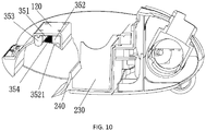
- the base comprises a turnable cover 110, a base shell 120, side shells 130, and a rear shell 140.
- the turnable cover 110 is disposed above the base shell 120 and may be flipped to open with respect to the base shell 120.
- the rear shell 140 is disposed at the lower rear of the base shell 120, and the side shells 130 are clamped at two sides of the base shell 120.
- the handle comprises a handle portion and a body portion.
- the handle portion comprises a top handle part 170 and a rear handle part 180.
- the body portion comprises a top body part 150 and a rear body part 160.
- the handle portion is mounted on the body portion.
- the body portion is connected to base through the adapter component 500 to realize the connection between the handle and the base.
- the cleaning mechanism comprises a cleaning roller assembly 210, a clearing component 220 operating to remove trash on the cleaning roller assembly, and a trash bin 230 for collecting the trash on the cleaning roller assembly.
- the cleaning roller assembly 210 comprises a cleaning roller.
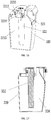
- the cleaning roller is made of flexible material, for example, in this example, the cleaning roller is a sponge roller 211.
- the cleaning roller assembly 210 further comprises a sleeve barrel 213 loading the sponge roller 211, and a power unit 212 for driving the sponge roller 211 and the sleeve barrel 213.
- the power unit 212 is disposed on the side wall of the base shell 120 and is locked using a bolt.
- the side wall is vertical to the ground.
- the sleeve barrel 213 of the sponge roller 211 is sleeved on the power unit 212 and is replaceable.
- the sponge roller 211 is sleeved on the sleeve barrel 213, and the power unit 212 is disposed in the sleeve barrel 213.
- the power unit 212 is optionally a motor, and the opening and closing of the power unit 212 is controlled by the control unit.
- the trash bin 230 is disposed at the lower rear of the sponge roller 211. Without affecting the rotation of the sponge roller 211, the trash bin can be close to the sponge roller 211 as possibly, so as to prevent the trash from leaking from the gap between the sponge roller 211 and the trash bin 230.
- the clearing component comprises a rotation body 221 and a plurality of clearing elements 222 disposed on the rotation body 221.
- the rotation body 221 is driven by a power unit (the power unit can be a motor, which is not shown in the drawings) to rotate along with the sponge roller 211 (clockwise or anticlockwise).
- the clearing elements 222 are strip-shaped, such as hair brush or tooth structures, and rotate with the rotation body 221.
- the gap between the clearing elements 222 and the sponge roller 211 is smaller than the volume of the trash or the clearing elements 222 and the sponge roller 211 directly contact with each other, so as to clear the trash on the sponge roller 211.
- the clearing component 220 is disposed at the upper rear of the sponge roller 211, i.e., above the trash bin 230, so that the trash cleared from the sponge roller 211 falls into the trash bin 230.
- the clearing elements 222 can be divided into at least two groups, each group comprises a plurality of clearing elements 222 which are disposed along the center line of rotation of the rotation body 221.
- the length of the clearing elements can be smaller than, larger than, or equal to the length of the sponge roller 211 along the center line of rotation of the rotation body 221.
- the clearing elements 222 can be aligned, or be disposed in the shape of wave. The latter can reduce the resistance of the clearing elements 222 against the sponge roller 211, thus saving the energy consumption.
- a scraper 240 is disposed at the rear of the sponge roller 211.
- the scraper 240 comprises a flexible front end 241 made of, for example, rubber.
- the front end 241 is attached to the ground, thus preventing the trash from omitting from the lower part of the cleaner.
- a gap exists between the scraper 240 and the sponge roller 211.
- the outer wall of the scraper 240 facing the sponge roller 211 is designed as an arc, and thus the gap operates as a guide channel to collect the trash.
- the water supply system comprises a washing chamber, a clean water tank 310, a clean water supply device (for example, water pump 330), a wastewater tank 320, and a wastewater recovery device (for example, air pump 340).
- the washing chamber is disposed on the rotation path of the sponge roller 211 and coordinates with the sponge roller 211 in a sealing mode.
- the washing chamber is filled with water to wash the sponge roller 211.
- the washing chamber is a water channel, or other chambers having a different structure.
- Part of the base shell 120 (can be regarded as the shell of the water channel) is concave to form the water channel 351, which simplifies the structure of the cleaner.
- the water channel 351 can be an individual structure.
- the water channel 351 is pressed on the sponge roller 211 in an overturn mode.
- the contact regions of the water channel 351 and the sponge roller 211 are sealed.
- a seal element 352 and a water-squeezing element 353 are locked at two sides of the water channel 351 via bolts, respectively.
- the seal element 352 is behind the water-squeezing element 353, that is to say, the sponge roller first moves to the seal element 352, and then to the water-squeezing element 353.
- the water-squeezing element 353 and the seal element 352 function as leak proof structures of the water channel 351 and the sponge roller 211, respectively.
- the water-squeezing element 353 operates to squeeze out the water in the sponge roller 211.
- the wastewater squeezed out from the sponge roller 211 directly flows to the water channel 351, and then collected by the wastewater tank 320.
- the water-squeezing element 353 is made of hard material, and the outer wall thereof contacting the sponge roller 211 is arc-shaped.
- the water-squeezing elements 353 are strips or shaft-shaped structures made of rigid plastic or metal.
- the seal element 352 only has the sealing properties. As shown in FIG. 1 1 , the contact part 3521 of the seal element 352 and sponge roller 211 is a bulge made of elastic material, the elasticity thereof can prevent the trash on the sponge roller 211 from being squeezed out of the water channel 351.
- a filter 354 is disposed in the water channel 351. Two ends of the filter 354 are pressed in the water channel 351 by the water-squeezing element 353 and the seal element 352.
- the clean water outlet 311 of the clean water tank 310, the clean water inlet (not shown in the drawings) of the water channel 351 communicate with the water pump 330.
- the water inlet of the water pump communicates with the clean water outlet 311, the water outlet 332 thereof communicates with the clean water inlet.
- clean water enters the water channel 351 via the clean water inlet to wash the sponge roller 211, and then flows out from the wastewater outlet 1241 of the water channel 351.
- the wastewater outlet 1241, the wastewater inlet 3211 of the wastewater tank 320 communicate with the air pump 340.
- the air pump 340 communicates with the air extraction opening 3212 of the wastewater tank 320
- the wastewater outlet 1241 of the water channel 351 communicates with the wastewater inlet 3211 of the wastewater tank 320.
- the air pump 340 operates to extract the air in the wastewater tank 320 to produce a negative environment, which is favorable to the wastewater tank 320 to absorb wastewater from the water channel 351.
- Employing the air pump 340 to absorb wastewater can flexibly control the wastewater tank 320 to absorb wastewater as needed.
- the clean water supply device is not limited to the water pump 330, it can also be an air pump instead of the water pump 330.
- the air pump communicates with the water channel 351. Through pumping, the pressure in the water channel 351 is decreased, the water channel sucks up clean water from the clean water tank 310.
- the working principle of the air pump is the same as the principle of the wastewater tank 320 for wastewater recovery.
- the wastewater recovery device is not limited to the air pump 340, it can also be a water pump instead of the air pump 340.
- the working principle of the water pump is the same as the principle of the clean water tank 310 for clean water supply.
- the wastewater tank 320 comprises a wastewater storage chamber and at least one splash-proof member.
- the splash-proof member separates the air extraction opening 3212 of the wastewater tank 320 from the storage chamber.
- the splash-proof member comprises an air vent communicating with the storage chamber.
- the air extraction opening 3212 of the wastewater tank 320 communicates with the air vent of the splash-proof member.
- Most of splashed foams are blocked by the splash-proof member, but the work of the air pump 340 is not affected. The more the splash-proof member, the better the splash-proof effect.
- the wastewater tank 320 comprises a chamber having the wastewater inlet 3211 and the air extraction opening 3212, a liquid level detector 322 and the splash-proof member 323.
- the liquid level detector 322 and the splash-proof member 323 both are disposed in the chamber.
- the liquid level detector 322 operates to detect the liquid level of the wastewater in the wastewater tank 320 and is connected to the control unit. When the wastewater overtakes the maximum, a switch is triggered to send signal to the control unit.
- the splash-proof member 323 comprises a first buffer chamber 3234 comprising first air vents 3231 at the top thereof and second air vents 3232 at the bottom thereof.
- the first air vents 3231 and the second air vents 3232 are disposed at different directions. Specifically, the first air vents 3231 are disposed vertically, and the second air vents 3232 are disposed transversely. The staggered arrangement of the air vents can prevent the water entering from the second air vents 3232 from entering the first air vents 3231.
- the chamber of the wastewater tank 320 is divided into a second buffer chamber 3233 and an accommodation chamber 3235.
- the second buffer chamber 3233 and the first buffer chamber 3234 communicate with each other via the first air vents 3231.
- the air extraction opening 3212 communicates with the second buffer chamber 3233. Therefore, through multiple levels of anti-splash, almost no water is pumped into the air pump 340.
- the air outlet 342 of the air pump 340 communicates with the sponge roller 211 or the water channel 351, and the water absorbed by the air pump 340 is discharged and collected by the sponge roller 211 or the water channel 351.
- the waterways of the water channel 351, the clean water tank 310, the water pump 330, the wastewater tank 320, and the air pump 340 can be independent pipes, or be integrated with other structures for simplifying the cleaner.
- two sides of the base shell 120 are provided with a clean water channel, a wastewater channel 124, and a water-discharging channel 125.
- One end of the wastewater channel 124 is the wastewater outlet 1241 of the water channel 351, and the other end thereof is a wastewater adaptor 1242 connected to the wastewater tank 320.
- One end of the water-discharging channel 125 is a water inlet 1251, and the other end thereof is a water outlet 1252 communicating with the water channel 351 or the sponge roller 211.
- the clean water channel is disposed at the base shell 120 and opposite to the wastewater channel 124, and comprises an adaptor communicating with the water pump 330 and the clean water inlet of the water channel 351.
- the structure of the clean water channel is basically the same as that of the wastewater channel 124, so no more detailed description should be provided for the clean water channel.
- the sponge roller 211 can be made much thicker. As a result, when washing the sponge, much more force must be exerted by the water-squeezing element 353 on the sponge roller 211 so as to squeeze water out of the sponge. However, when the squeezing force is much large, the rotation of the sponge roller 211 may be impeded, and to maintain the normal rotation of the sponge roller 211, much more energy must be imposed, thus causing more energy consumption.
- the sponge roller 211 comprises at least two layers, that is, an outer layer and an inner layer.
- the outer layer is an absorbent spongy layer 2111 and the inner layer is non-absorbent spongy layer 2112.
- the non-absorbent spongy layer 2112 is made of non-absorbent sponge and is incapable of absorbing water.
- the absorbent spongy layer 2111 is made of absorbent sponge, and water is mainly absorbed by the outer absorbent spongy layer 2111. Thus, to squeeze out water, only need to squeeze out water in the outer absorbent spongy layer 2111. Because the outer absorbent spongy layer is thinner than conventional spongy layer, the external force used for squeezing out water is gentle and does not impede the rotation of the sponge roller 211.
- the sponge roller 211 is disposed in the base shell 120.
- Two ends of conventional cylindrical sponge roller are a circular surface vertical to the ground.
- the left and right side walls of the base shell 120 have a certain thickness, so that the sponge roller 120 cannot stretch into the region below the left and right side walls of the base shell 120 adjacent to the sponge roller 211 due to the circular structure of the sponge roller. As a result, the regions below the left and right side walls of the base shell 120 adjacent to the sponge roller 211 cannot be cleaned.
- At least one end of the sponge roller 211 is a conical surface along the axial direction.
- two conical surfaces are provided, as shown in a and b.
- the conical surfaces a and b can stretch into the lower part of the left and right side walls of the base shell 120 adjacent to the sponge roller 211, thus cleaning the ground completely.
- the control unit comprises a circuit board loading a control circuit and a man-machine interaction unit. Because the control unit is not the key point of improvement of the disclosure, no detailed description is provided herein.
- FIG.3 shows keys of the man-machine interaction unit.
Landscapes
- Cleaning Implements For Floors, Carpets, Furniture, Walls, And The Like (AREA)
- Cleaning In General (AREA)
- Nozzles For Electric Vacuum Cleaners (AREA)
Priority Applications (4)
| Application Number | Priority Date | Filing Date | Title |
|---|---|---|---|
| PT15905699T PT3238596T (pt) | 2015-10-10 | 2015-10-10 | Equipamento de limpeza para o chão, componente de rolo de limpeza e rolo de esponja |
| PL15905699T PL3238596T3 (pl) | 2015-10-10 | 2015-10-10 | Urządzenie do czyszczenia podłogi, element wałka czyszczącego i wałek piankowy |
| HUE15905699A HUE045855T2 (hu) | 2015-10-10 | 2015-10-10 | Padlótisztító, tisztítóhenger komponens és szivacshenger |
| EP19174624.7A EP3556274A1 (en) | 2015-10-10 | 2015-10-10 | Floor cleaner, cleaning roller component, and sponge roller |
Applications Claiming Priority (1)
| Application Number | Priority Date | Filing Date | Title |
|---|---|---|---|
| PCT/CN2015/091683 WO2017059601A1 (zh) | 2015-10-10 | 2015-10-10 | 地面清洁器、清洁筒组件及海绵筒 |
Related Child Applications (2)
| Application Number | Title | Priority Date | Filing Date |
|---|---|---|---|
| EP19174624.7A Division EP3556274A1 (en) | 2015-10-10 | 2015-10-10 | Floor cleaner, cleaning roller component, and sponge roller |
| EP19174624.7A Division-Into EP3556274A1 (en) | 2015-10-10 | 2015-10-10 | Floor cleaner, cleaning roller component, and sponge roller |
Publications (3)
| Publication Number | Publication Date |
|---|---|
| EP3238596A1 EP3238596A1 (en) | 2017-11-01 |
| EP3238596A4 EP3238596A4 (en) | 2018-09-05 |
| EP3238596B1 true EP3238596B1 (en) | 2019-07-03 |
Family
ID=58487175
Family Applications (2)
| Application Number | Title | Priority Date | Filing Date |
|---|---|---|---|
| EP15905699.3A Active EP3238596B1 (en) | 2015-10-10 | 2015-10-10 | Floor cleaner, cleaning roller component, and sponge roller |
| EP19174624.7A Withdrawn EP3556274A1 (en) | 2015-10-10 | 2015-10-10 | Floor cleaner, cleaning roller component, and sponge roller |
Family Applications After (1)
| Application Number | Title | Priority Date | Filing Date |
|---|---|---|---|
| EP19174624.7A Withdrawn EP3556274A1 (en) | 2015-10-10 | 2015-10-10 | Floor cleaner, cleaning roller component, and sponge roller |
Country Status (10)
| Country | Link |
|---|---|
| US (2) | US10052007B2 (ko) |
| EP (2) | EP3238596B1 (ko) |
| JP (1) | JP2018506413A (ko) |
| KR (1) | KR102093377B1 (ko) |
| CN (1) | CN108135420B (ko) |
| ES (1) | ES2746113T3 (ko) |
| HU (1) | HUE045855T2 (ko) |
| PL (1) | PL3238596T3 (ko) |
| PT (1) | PT3238596T (ko) |
| WO (1) | WO2017059601A1 (ko) |
Families Citing this family (29)
| Publication number | Priority date | Publication date | Assignee | Title |
|---|---|---|---|---|
| USD897059S1 (en) * | 2017-10-20 | 2020-09-22 | Shenzhen Hizero Technologies Co., Ltd. | Floor cleaner |
| CN110636790B (zh) | 2018-02-13 | 2021-10-01 | 深圳市赫兹家电有限公司 | 扫地机器人及其清洁装置 |
| IT201800010902A1 (it) | 2018-12-07 | 2020-06-07 | Plastecs S R L | Apparecchio per il trattamento di superfici calpestabili, come ad esempio pavimenti |
| KR102707557B1 (ko) * | 2019-04-04 | 2024-09-19 | 삼성전자주식회사 | 청소기 및 청소기의 브러시 드럼 제조방법 |
| CN113710139A (zh) | 2019-04-12 | 2021-11-26 | 阿尔弗雷德·卡赫欧洲两合公司 | 带增强模式的表面清洁机和用于运行表面清洁机的方法 |
| GB2584311B8 (en) * | 2019-05-30 | 2021-08-18 | Lupe Tech Limited | Rollers for vacuum cleaners |
| US11503976B2 (en) * | 2019-09-06 | 2022-11-22 | Brenda Stone | Cleaning apparatus |
| CN212368899U (zh) * | 2020-06-17 | 2021-01-19 | 深圳市探博智能机器人有限公司 | 用于扫地机器人的清洗装置 |
| KR102209199B1 (ko) | 2020-06-19 | 2021-01-29 | 홍연기 | 세레이션 롤러 제작방법 및 운용방법 |
| CN113565054B (zh) * | 2021-07-22 | 2023-10-31 | 安徽华信电动科技股份有限公司 | 一种基于电池动力的小型三轮环卫清污车 |
| DE102021134552A1 (de) | 2021-12-23 | 2023-06-29 | Alfred Kärcher SE & Co. KG | Bodenreinigungsmaschine mit Schwenkgelenk und Verfahren zum Betreiben einer Bodenreinigungsmaschine |
| DE102021134463A1 (de) | 2021-12-23 | 2023-07-13 | Alfred Kärcher SE & Co. KG | Flächenreinigungsmaschine mit gekrümmtem Abstreifelement |
| DE102021134577A1 (de) | 2021-12-23 | 2023-06-29 | Alfred Kärcher SE & Co. KG | Bodenreinigungsmaschine mit Trittlasche und Verfahren zur Abnahme einer Schmutzfluidtankeinrichtung von einem Reinigungskopf |
| DE102021134612A1 (de) | 2021-12-23 | 2023-06-29 | Alfred Kärcher SE & Co. KG | Bodenreinigungsmaschine mit mindestens einem Abstützelement |
| DE202022101312U1 (de) | 2022-02-08 | 2022-06-20 | Alfred Kärcher SE & Co. KG | Bodenreinigungsgerät mit Kassette |
| DE202022101313U1 (de) | 2022-02-08 | 2022-06-20 | Alfred Kärcher SE & Co. KG | Bodenreinigungsgerät mit beweglichem Abstreifelement |
| DE102022102918A1 (de) | 2022-02-08 | 2023-08-10 | Alfred Kärcher SE & Co. KG | Bodenreinigungsgerät mit Kassette |
| DE102022102924A1 (de) | 2022-02-08 | 2023-08-10 | Alfred Kärcher SE & Co. KG | Bodenreinigungsgerät mit beweglichem Abstreifelement |
| DE102022133009A1 (de) | 2022-02-08 | 2023-08-10 | Alfred Kärcher SE & Co. KG | Bodenreinigungsgerät mit Drehlagereinrichtung mit Widerlager |
| DE202022101314U1 (de) | 2022-02-08 | 2022-06-20 | Alfred Kärcher SE & Co. KG | Bodenreinigungsgerät mit Schmutzfluid-Tank |
| EP4475732A1 (de) | 2022-02-08 | 2024-12-18 | Alfred Kärcher SE & Co. KG | Bodenreinigungsgerät mit drehlagereinrichtung mit widerlager |
| WO2023151833A1 (de) | 2022-02-08 | 2023-08-17 | Alfred Kärcher SE & Co. KG | Bodenreinigungsgerät mit kehreinrichtung und verfahren zum betreiben eines bodenreinigungsgeräts |
| DE102022102937A1 (de) | 2022-02-08 | 2023-08-10 | Alfred Kärcher SE & Co. KG | Bodenreinigungsgerät mit Schmutzfluid-Tank |
| GB2616903B (en) * | 2022-03-25 | 2024-06-26 | Dyson Technology Ltd | Hard floor cleaner |
| DE102022124120A1 (de) | 2022-09-20 | 2024-03-21 | Alfred Kärcher SE & Co. KG | Bodenreinigungsgerät mit Becken und Verfahren zum Betreiben eines Bodenreinigungsgeräts |
| DE102022133006A1 (de) | 2022-12-12 | 2024-06-13 | Alfred Kärcher SE & Co. KG | Bodenreinigungsgerät mit Schmutzfluid-Tank mit zwei Bereichen |
| DE102022133004A1 (de) | 2022-12-12 | 2024-06-13 | Alfred Kärcher SE & Co. KG | Bodenreinigungsgerät mit Bodenkopf mit Wandung |
| EP4665193A1 (de) | 2023-02-16 | 2025-12-24 | Alfred Kärcher SE & Co. KG | Bodenreinigungsmaschine mit basismodul und reinigungsmodul |
| DE102023104615A1 (de) | 2023-02-24 | 2024-08-29 | Alfred Kärcher SE & Co. KG | Flächenreinigungsmaschine mit Heißfluiderzeugungseinrichtung und Verfahren zum Betreiben einer Flächenreinigungsmaschine |
Family Cites Families (27)
| Publication number | Priority date | Publication date | Assignee | Title |
|---|---|---|---|---|
| FR651101A (fr) | 1927-03-29 | 1929-02-14 | Balai-frotteuse à commande électrique | |
| US2881461A (en) * | 1956-10-29 | 1959-04-14 | Wynton E Parker | Paint roller for curved surfaces |
| US3172138A (en) * | 1963-09-16 | 1965-03-09 | William B Price | Surface treating apparatus |
| JPS5029975B2 (ko) * | 1972-04-24 | 1975-09-27 | ||
| US4959628A (en) * | 1988-07-22 | 1990-09-25 | Quad Research, Inc. | Rotating electric switch actuated by fixed magnetic means, usable for a surface cleaning device |
| CN2241510Y (zh) | 1995-05-31 | 1996-12-04 | 谢嘉益 | 一种拖把 |
| DE19805900C1 (de) * | 1998-02-13 | 1999-07-29 | Duepro Ag | Saugreinigungswerkzeug mit ausschwenkbarer Bürstenwalze |
| DE10001467B4 (de) * | 2000-01-15 | 2004-04-08 | Düpro AG | Saugreinigungswerkzeug |
| US7279050B2 (en) * | 2002-10-29 | 2007-10-09 | Xerox Corporation | One-piece bottom edge wipe sponge for cleaning a photoreceptor drum |
| US8079112B2 (en) | 2004-11-17 | 2011-12-20 | Butler Home Products, Llc | Disposable liquid absorbing cleaning pad for a hand held cleaning implement having an elongated handle |
| CN2794412Y (zh) | 2005-04-09 | 2006-07-12 | 袁仁华 | 湿式滚筒吸尘器 |
| US7979952B2 (en) * | 2006-12-13 | 2011-07-19 | Ab Electrolux | Wet/dry floor cleaning device |
| CN100581433C (zh) * | 2007-03-29 | 2010-01-20 | 杜爵伟 | 结合具有扫地功能的擦地装置的地面清洁器 |
| DE102007052982A1 (de) * | 2007-11-07 | 2009-05-14 | Vorwerk & Co. Interholding Gmbh | Reinigungsgerät sowie Reinigungswalze für ein Reinigungsgerät |
| CN102087501A (zh) * | 2009-12-02 | 2011-06-08 | 深圳市宝安区松岗富士(中国)制品厂 | 清洗辊筒及其制造方法以及其制造模具 |
| IT1402118B1 (it) * | 2010-09-15 | 2013-08-28 | Bettuzzi | Macchina lavasciuga-spazzante. |
| KR101573742B1 (ko) | 2010-10-25 | 2015-12-07 | 삼성전자주식회사 | 로봇청소기 |
| JP5230775B2 (ja) * | 2011-06-09 | 2013-07-10 | 惠司 細川 | 結露除去具 |
| KR101452617B1 (ko) * | 2013-03-08 | 2014-10-22 | 박미경 | 미세먼지 제거용 진공청소기 |
| US9682399B2 (en) * | 2013-03-15 | 2017-06-20 | Affordable Countertop Solutions, Inc. | Paint roller |
| TWM469037U (zh) | 2013-05-07 | 2014-01-01 | qing-ji Lin | 電動掃洗裝置 |
| CN203263303U (zh) | 2013-05-23 | 2013-11-06 | 林清吉 | 电动扫洗装置 |
| CN203506629U (zh) * | 2013-06-20 | 2014-04-02 | 苏州经贸职业技术学院 | 一种多功能清洁器 |
| CN203458324U (zh) * | 2013-07-08 | 2014-03-05 | 范施嫡 | 玻璃擦 |
| US20150082579A1 (en) | 2013-09-26 | 2015-03-26 | Ching-Chi Lin | Electric sweeping washing device |
| CN204096530U (zh) * | 2014-07-21 | 2015-01-14 | 安徽中瀚节能环保科技有限公司 | 一种海绵体清洁托辊 |
| US9713411B2 (en) * | 2014-10-20 | 2017-07-25 | The Kirby Company / Scott Fetzer Company | Surface-treatment apparatus and head unit |
-
2015
- 2015-10-10 PT PT15905699T patent/PT3238596T/pt unknown
- 2015-10-10 JP JP2017563376A patent/JP2018506413A/ja active Pending
- 2015-10-10 CN CN201580083997.4A patent/CN108135420B/zh active Active
- 2015-10-10 PL PL15905699T patent/PL3238596T3/pl unknown
- 2015-10-10 HU HUE15905699A patent/HUE045855T2/hu unknown
- 2015-10-10 KR KR1020187013363A patent/KR102093377B1/ko active Active
- 2015-10-10 EP EP15905699.3A patent/EP3238596B1/en active Active
- 2015-10-10 ES ES15905699T patent/ES2746113T3/es active Active
- 2015-10-10 US US15/122,437 patent/US10052007B2/en active Active
- 2015-10-10 EP EP19174624.7A patent/EP3556274A1/en not_active Withdrawn
- 2015-10-10 WO PCT/CN2015/091683 patent/WO2017059601A1/zh not_active Ceased
-
2018
- 2018-08-20 US US16/105,339 patent/US10898048B2/en active Active
Non-Patent Citations (1)
| Title |
|---|
| None * |
Also Published As
| Publication number | Publication date |
|---|---|
| EP3238596A1 (en) | 2017-11-01 |
| US20180199787A1 (en) | 2018-07-19 |
| EP3556274A1 (en) | 2019-10-23 |
| KR20180098228A (ko) | 2018-09-03 |
| PT3238596T (pt) | 2019-08-06 |
| WO2017059601A1 (zh) | 2017-04-13 |
| CN108135420A (zh) | 2018-06-08 |
| KR102093377B1 (ko) | 2020-03-26 |
| US10898048B2 (en) | 2021-01-26 |
| PL3238596T3 (pl) | 2020-02-28 |
| HUE045855T2 (hu) | 2020-01-28 |
| EP3238596A4 (en) | 2018-09-05 |
| US10052007B2 (en) | 2018-08-21 |
| JP2018506413A (ja) | 2018-03-08 |
| CN108135420B (zh) | 2021-04-09 |
| US20180353046A1 (en) | 2018-12-13 |
| ES2746113T3 (es) | 2020-03-04 |
Similar Documents
| Publication | Publication Date | Title |
|---|---|---|
| US10898048B2 (en) | Floor cleaner, cleaning roller assembly, and sponge roller | |
| US10786134B2 (en) | Floor cleaner and water channel | |
| US10912436B2 (en) | Floor cleaner, and cleaning mechanism for clearing cleaning roller | |
| KR102072512B1 (ko) | 바닥 청소기 | |
| CN205181250U (zh) | 地面清洁器 | |
| CN205181251U (zh) | 地面清洁器、清洁筒组件及海绵筒 | |
| CN205181257U (zh) | 地面清洁器及其水槽结构 | |
| CN205181256U (zh) | 地面清洁器及其清洁筒清理结构 | |
| JP2019107563A (ja) | 床面掃除機及びその水槽構造 | |
| JP2019115789A (ja) | 床面掃除機 |
Legal Events
| Date | Code | Title | Description |
|---|---|---|---|
| STAA | Information on the status of an ep patent application or granted ep patent |
Free format text: STATUS: THE INTERNATIONAL PUBLICATION HAS BEEN MADE |
|
| PUAI | Public reference made under article 153(3) epc to a published international application that has entered the european phase |
Free format text: ORIGINAL CODE: 0009012 |
|
| STAA | Information on the status of an ep patent application or granted ep patent |
Free format text: STATUS: REQUEST FOR EXAMINATION WAS MADE |
|
| 17P | Request for examination filed |
Effective date: 20170727 |
|
| AK | Designated contracting states |
Kind code of ref document: A1 Designated state(s): AL AT BE BG CH CY CZ DE DK EE ES FI FR GB GR HR HU IE IS IT LI LT LU LV MC MK MT NL NO PL PT RO RS SE SI SK SM TR |
|
| AX | Request for extension of the european patent |
Extension state: BA ME |
|
| A4 | Supplementary search report drawn up and despatched |
Effective date: 20180808 |
|
| RIC1 | Information provided on ipc code assigned before grant |
Ipc: A47L 11/40 20060101ALI20180802BHEP Ipc: A47L 11/26 20060101AFI20180802BHEP |
|
| DAV | Request for validation of the european patent (deleted) | ||
| DAX | Request for extension of the european patent (deleted) | ||
| GRAP | Despatch of communication of intention to grant a patent |
Free format text: ORIGINAL CODE: EPIDOSNIGR1 |
|
| STAA | Information on the status of an ep patent application or granted ep patent |
Free format text: STATUS: GRANT OF PATENT IS INTENDED |
|
| INTG | Intention to grant announced |
Effective date: 20190213 |
|
| GRAS | Grant fee paid |
Free format text: ORIGINAL CODE: EPIDOSNIGR3 |
|
| GRAA | (expected) grant |
Free format text: ORIGINAL CODE: 0009210 |
|
| STAA | Information on the status of an ep patent application or granted ep patent |
Free format text: STATUS: THE PATENT HAS BEEN GRANTED |
|
| AK | Designated contracting states |
Kind code of ref document: B1 Designated state(s): AL AT BE BG CH CY CZ DE DK EE ES FI FR GB GR HR HU IE IS IT LI LT LU LV MC MK MT NL NO PL PT RO RS SE SI SK SM TR |
|
| REG | Reference to a national code |
Ref country code: GB Ref legal event code: FG4D |
|
| REG | Reference to a national code |
Ref country code: CH Ref legal event code: EP Ref country code: AT Ref legal event code: REF Ref document number: 1149963 Country of ref document: AT Kind code of ref document: T Effective date: 20190715 |
|
| REG | Reference to a national code |
Ref country code: DE Ref legal event code: R096 Ref document number: 602015033368 Country of ref document: DE |
|
| REG | Reference to a national code |
Ref country code: IE Ref legal event code: FG4D |
|
| REG | Reference to a national code |
Ref country code: PT Ref legal event code: SC4A Ref document number: 3238596 Country of ref document: PT Date of ref document: 20190806 Kind code of ref document: T Free format text: AVAILABILITY OF NATIONAL TRANSLATION Effective date: 20190731 |
|
| REG | Reference to a national code |
Ref country code: NL Ref legal event code: FP |
|
| REG | Reference to a national code |
Ref country code: SE Ref legal event code: TRGR |
|
| REG | Reference to a national code |
Ref country code: LT Ref legal event code: MG4D |
|
| REG | Reference to a national code |
Ref country code: HU Ref legal event code: AG4A Ref document number: E045855 Country of ref document: HU |
|
| PG25 | Lapsed in a contracting state [announced via postgrant information from national office to epo] |
Ref country code: LT Free format text: LAPSE BECAUSE OF FAILURE TO SUBMIT A TRANSLATION OF THE DESCRIPTION OR TO PAY THE FEE WITHIN THE PRESCRIBED TIME-LIMIT Effective date: 20190703 Ref country code: FI Free format text: LAPSE BECAUSE OF FAILURE TO SUBMIT A TRANSLATION OF THE DESCRIPTION OR TO PAY THE FEE WITHIN THE PRESCRIBED TIME-LIMIT Effective date: 20190703 Ref country code: BG Free format text: LAPSE BECAUSE OF FAILURE TO SUBMIT A TRANSLATION OF THE DESCRIPTION OR TO PAY THE FEE WITHIN THE PRESCRIBED TIME-LIMIT Effective date: 20191003 Ref country code: NO Free format text: LAPSE BECAUSE OF FAILURE TO SUBMIT A TRANSLATION OF THE DESCRIPTION OR TO PAY THE FEE WITHIN THE PRESCRIBED TIME-LIMIT Effective date: 20191003 Ref country code: HR Free format text: LAPSE BECAUSE OF FAILURE TO SUBMIT A TRANSLATION OF THE DESCRIPTION OR TO PAY THE FEE WITHIN THE PRESCRIBED TIME-LIMIT Effective date: 20190703 |
|
| PGFP | Annual fee paid to national office [announced via postgrant information from national office to epo] |
Ref country code: SE Payment date: 20191010 Year of fee payment: 5 Ref country code: PT Payment date: 20191010 Year of fee payment: 5 Ref country code: HU Payment date: 20191031 Year of fee payment: 5 Ref country code: NL Payment date: 20191014 Year of fee payment: 5 |
|
| PG25 | Lapsed in a contracting state [announced via postgrant information from national office to epo] |
Ref country code: GR Free format text: LAPSE BECAUSE OF FAILURE TO SUBMIT A TRANSLATION OF THE DESCRIPTION OR TO PAY THE FEE WITHIN THE PRESCRIBED TIME-LIMIT Effective date: 20191004 Ref country code: RS Free format text: LAPSE BECAUSE OF FAILURE TO SUBMIT A TRANSLATION OF THE DESCRIPTION OR TO PAY THE FEE WITHIN THE PRESCRIBED TIME-LIMIT Effective date: 20190703 Ref country code: IS Free format text: LAPSE BECAUSE OF FAILURE TO SUBMIT A TRANSLATION OF THE DESCRIPTION OR TO PAY THE FEE WITHIN THE PRESCRIBED TIME-LIMIT Effective date: 20191103 Ref country code: AL Free format text: LAPSE BECAUSE OF FAILURE TO SUBMIT A TRANSLATION OF THE DESCRIPTION OR TO PAY THE FEE WITHIN THE PRESCRIBED TIME-LIMIT Effective date: 20190703 Ref country code: LV Free format text: LAPSE BECAUSE OF FAILURE TO SUBMIT A TRANSLATION OF THE DESCRIPTION OR TO PAY THE FEE WITHIN THE PRESCRIBED TIME-LIMIT Effective date: 20190703 |
|
| PGFP | Annual fee paid to national office [announced via postgrant information from national office to epo] |
Ref country code: IT Payment date: 20191021 Year of fee payment: 5 Ref country code: ES Payment date: 20191104 Year of fee payment: 5 Ref country code: FR Payment date: 20191029 Year of fee payment: 5 |
|
| REG | Reference to a national code |
Ref country code: ES Ref legal event code: FG2A Ref document number: 2746113 Country of ref document: ES Kind code of ref document: T3 Effective date: 20200304 |
|
| PGFP | Annual fee paid to national office [announced via postgrant information from national office to epo] |
Ref country code: TR Payment date: 20191010 Year of fee payment: 5 |
|
| PG25 | Lapsed in a contracting state [announced via postgrant information from national office to epo] |
Ref country code: DK Free format text: LAPSE BECAUSE OF FAILURE TO SUBMIT A TRANSLATION OF THE DESCRIPTION OR TO PAY THE FEE WITHIN THE PRESCRIBED TIME-LIMIT Effective date: 20190703 Ref country code: EE Free format text: LAPSE BECAUSE OF FAILURE TO SUBMIT A TRANSLATION OF THE DESCRIPTION OR TO PAY THE FEE WITHIN THE PRESCRIBED TIME-LIMIT Effective date: 20190703 Ref country code: RO Free format text: LAPSE BECAUSE OF FAILURE TO SUBMIT A TRANSLATION OF THE DESCRIPTION OR TO PAY THE FEE WITHIN THE PRESCRIBED TIME-LIMIT Effective date: 20190703 |
|
| PGFP | Annual fee paid to national office [announced via postgrant information from national office to epo] |
Ref country code: PL Payment date: 20191010 Year of fee payment: 5 Ref country code: GB Payment date: 20191018 Year of fee payment: 5 |
|
| PG25 | Lapsed in a contracting state [announced via postgrant information from national office to epo] |
Ref country code: SM Free format text: LAPSE BECAUSE OF FAILURE TO SUBMIT A TRANSLATION OF THE DESCRIPTION OR TO PAY THE FEE WITHIN THE PRESCRIBED TIME-LIMIT Effective date: 20190703 Ref country code: IS Free format text: LAPSE BECAUSE OF FAILURE TO SUBMIT A TRANSLATION OF THE DESCRIPTION OR TO PAY THE FEE WITHIN THE PRESCRIBED TIME-LIMIT Effective date: 20200224 Ref country code: SK Free format text: LAPSE BECAUSE OF FAILURE TO SUBMIT A TRANSLATION OF THE DESCRIPTION OR TO PAY THE FEE WITHIN THE PRESCRIBED TIME-LIMIT Effective date: 20190703 Ref country code: MC Free format text: LAPSE BECAUSE OF FAILURE TO SUBMIT A TRANSLATION OF THE DESCRIPTION OR TO PAY THE FEE WITHIN THE PRESCRIBED TIME-LIMIT Effective date: 20190703 |
|
| PGFP | Annual fee paid to national office [announced via postgrant information from national office to epo] |
Ref country code: CZ Payment date: 20191010 Year of fee payment: 5 |
|
| REG | Reference to a national code |
Ref country code: CH Ref legal event code: PL |
|
| REG | Reference to a national code |
Ref country code: DE Ref legal event code: R097 Ref document number: 602015033368 Country of ref document: DE |
|
| REG | Reference to a national code |
Ref country code: AT Ref legal event code: UEP Ref document number: 1149963 Country of ref document: AT Kind code of ref document: T Effective date: 20190703 |
|
| PLBE | No opposition filed within time limit |
Free format text: ORIGINAL CODE: 0009261 |
|
| STAA | Information on the status of an ep patent application or granted ep patent |
Free format text: STATUS: NO OPPOSITION FILED WITHIN TIME LIMIT |
|
| PG2D | Information on lapse in contracting state deleted |
Ref country code: IS |
|
| PG25 | Lapsed in a contracting state [announced via postgrant information from national office to epo] |
Ref country code: LU Free format text: LAPSE BECAUSE OF NON-PAYMENT OF DUE FEES Effective date: 20191010 Ref country code: LI Free format text: LAPSE BECAUSE OF NON-PAYMENT OF DUE FEES Effective date: 20191031 Ref country code: CH Free format text: LAPSE BECAUSE OF NON-PAYMENT OF DUE FEES Effective date: 20191031 |
|
| 26N | No opposition filed |
Effective date: 20200603 |
|
| REG | Reference to a national code |
Ref country code: BE Ref legal event code: MM Effective date: 20191031 |
|
| PG25 | Lapsed in a contracting state [announced via postgrant information from national office to epo] |
Ref country code: SI Free format text: LAPSE BECAUSE OF FAILURE TO SUBMIT A TRANSLATION OF THE DESCRIPTION OR TO PAY THE FEE WITHIN THE PRESCRIBED TIME-LIMIT Effective date: 20190703 Ref country code: BE Free format text: LAPSE BECAUSE OF NON-PAYMENT OF DUE FEES Effective date: 20191031 |
|
| PG25 | Lapsed in a contracting state [announced via postgrant information from national office to epo] |
Ref country code: IE Free format text: LAPSE BECAUSE OF NON-PAYMENT OF DUE FEES Effective date: 20191010 |
|
| PG25 | Lapsed in a contracting state [announced via postgrant information from national office to epo] |
Ref country code: CZ Free format text: LAPSE BECAUSE OF NON-PAYMENT OF DUE FEES Effective date: 20201010 |
|
| PG25 | Lapsed in a contracting state [announced via postgrant information from national office to epo] |
Ref country code: CY Free format text: LAPSE BECAUSE OF FAILURE TO SUBMIT A TRANSLATION OF THE DESCRIPTION OR TO PAY THE FEE WITHIN THE PRESCRIBED TIME-LIMIT Effective date: 20190703 |
|
| REG | Reference to a national code |
Ref country code: SE Ref legal event code: EUG |
|
| REG | Reference to a national code |
Ref country code: NL Ref legal event code: MM Effective date: 20201101 |
|
| REG | Reference to a national code |
Ref country code: DE Ref legal event code: R082 Ref document number: 602015033368 Country of ref document: DE Representative=s name: LAMBSDORFF & LANGE PATENTANWAELTE PARTNERSCHAF, DE Ref country code: DE Ref legal event code: R081 Ref document number: 602015033368 Country of ref document: DE Owner name: HIZERO APPLIANCES CORPORATION, CN Free format text: FORMER OWNER: HIZERO TECHNOLOGIES CO., LTD., SHENZHEN, GUANGDONG, CN |
|
| GBPC | Gb: european patent ceased through non-payment of renewal fee |
Effective date: 20201010 |
|
| PG25 | Lapsed in a contracting state [announced via postgrant information from national office to epo] |
Ref country code: PT Free format text: LAPSE BECAUSE OF NON-PAYMENT OF DUE FEES Effective date: 20210412 Ref country code: FR Free format text: LAPSE BECAUSE OF NON-PAYMENT OF DUE FEES Effective date: 20201031 Ref country code: MT Free format text: LAPSE BECAUSE OF FAILURE TO SUBMIT A TRANSLATION OF THE DESCRIPTION OR TO PAY THE FEE WITHIN THE PRESCRIBED TIME-LIMIT Effective date: 20190703 |
|
| PG25 | Lapsed in a contracting state [announced via postgrant information from national office to epo] |
Ref country code: HU Free format text: LAPSE BECAUSE OF NON-PAYMENT OF DUE FEES Effective date: 20201011 Ref country code: GB Free format text: LAPSE BECAUSE OF NON-PAYMENT OF DUE FEES Effective date: 20201010 Ref country code: SE Free format text: LAPSE BECAUSE OF NON-PAYMENT OF DUE FEES Effective date: 20201011 |
|
| PG25 | Lapsed in a contracting state [announced via postgrant information from national office to epo] |
Ref country code: IT Free format text: LAPSE BECAUSE OF NON-PAYMENT OF DUE FEES Effective date: 20201010 |
|
| REG | Reference to a national code |
Ref country code: AT Ref legal event code: MM01 Ref document number: 1149963 Country of ref document: AT Kind code of ref document: T Effective date: 20201010 |
|
| REG | Reference to a national code |
Ref country code: ES Ref legal event code: FD2A Effective date: 20220120 |
|
| PG25 | Lapsed in a contracting state [announced via postgrant information from national office to epo] |
Ref country code: AT Free format text: LAPSE BECAUSE OF NON-PAYMENT OF DUE FEES Effective date: 20201010 |
|
| PG25 | Lapsed in a contracting state [announced via postgrant information from national office to epo] |
Ref country code: ES Free format text: LAPSE BECAUSE OF NON-PAYMENT OF DUE FEES Effective date: 20201011 |
|
| PG25 | Lapsed in a contracting state [announced via postgrant information from national office to epo] |
Ref country code: TR Free format text: LAPSE BECAUSE OF NON-PAYMENT OF DUE FEES Effective date: 20201010 Ref country code: MK Free format text: LAPSE BECAUSE OF FAILURE TO SUBMIT A TRANSLATION OF THE DESCRIPTION OR TO PAY THE FEE WITHIN THE PRESCRIBED TIME-LIMIT Effective date: 20190703 |
|
| PG25 | Lapsed in a contracting state [announced via postgrant information from national office to epo] |
Ref country code: PL Free format text: LAPSE BECAUSE OF NON-PAYMENT OF DUE FEES Effective date: 20201010 |
|
| PG25 | Lapsed in a contracting state [announced via postgrant information from national office to epo] |
Ref country code: NL Free format text: LAPSE BECAUSE OF NON-PAYMENT OF DUE FEES Effective date: 20200101 |
|
| PGFP | Annual fee paid to national office [announced via postgrant information from national office to epo] |
Ref country code: DE Payment date: 20241022 Year of fee payment: 10 |