EP3237779B1 - Spindelantrieb mit einem gehäuse, einer spindel, und einer mit der spindel in wirkverbindung stehenden spindelmutter - Google Patents
Spindelantrieb mit einem gehäuse, einer spindel, und einer mit der spindel in wirkverbindung stehenden spindelmutter Download PDFInfo
- Publication number
- EP3237779B1 EP3237779B1 EP15812949.4A EP15812949A EP3237779B1 EP 3237779 B1 EP3237779 B1 EP 3237779B1 EP 15812949 A EP15812949 A EP 15812949A EP 3237779 B1 EP3237779 B1 EP 3237779B1
- Authority
- EP
- European Patent Office
- Prior art keywords
- spindle
- annular groove
- screw
- spindle nut
- housing
- Prior art date
- Legal status (The legal status is an assumption and is not a legal conclusion. Google has not performed a legal analysis and makes no representation as to the accuracy of the status listed.)
- Active
Links
- 230000005540 biological transmission Effects 0.000 title 1
- 230000003993 interaction Effects 0.000 title 1
- 229920003023 plastic Polymers 0.000 claims description 5
- 239000004033 plastic Substances 0.000 claims description 5
- 238000007373 indentation Methods 0.000 claims 1
- 239000000463 material Substances 0.000 claims 1
- 230000002093 peripheral effect Effects 0.000 claims 1
- 239000000203 mixture Substances 0.000 description 8
- 230000005484 gravity Effects 0.000 description 4
- 230000006835 compression Effects 0.000 description 2
- 238000007906 compression Methods 0.000 description 2
- 238000009434 installation Methods 0.000 description 2
- 230000035515 penetration Effects 0.000 description 2
- 238000007789 sealing Methods 0.000 description 2
- 230000008878 coupling Effects 0.000 description 1
- 238000010168 coupling process Methods 0.000 description 1
- 238000005859 coupling reaction Methods 0.000 description 1
- 238000013016 damping Methods 0.000 description 1
- 238000010348 incorporation Methods 0.000 description 1
Images


Classifications
-
- F—MECHANICAL ENGINEERING; LIGHTING; HEATING; WEAPONS; BLASTING
- F16—ENGINEERING ELEMENTS AND UNITS; GENERAL MEASURES FOR PRODUCING AND MAINTAINING EFFECTIVE FUNCTIONING OF MACHINES OR INSTALLATIONS; THERMAL INSULATION IN GENERAL
- F16H—GEARING
- F16H25/00—Gearings comprising primarily only cams, cam-followers and screw-and-nut mechanisms
- F16H25/18—Gearings comprising primarily only cams, cam-followers and screw-and-nut mechanisms for conveying or interconverting oscillating or reciprocating motions
- F16H25/20—Screw mechanisms
- F16H25/2015—Means specially adapted for stopping actuators in the end position; Position sensing means
-
- F—MECHANICAL ENGINEERING; LIGHTING; HEATING; WEAPONS; BLASTING
- F16—ENGINEERING ELEMENTS AND UNITS; GENERAL MEASURES FOR PRODUCING AND MAINTAINING EFFECTIVE FUNCTIONING OF MACHINES OR INSTALLATIONS; THERMAL INSULATION IN GENERAL
- F16H—GEARING
- F16H57/00—General details of gearing
- F16H57/04—Features relating to lubrication or cooling or heating
- F16H57/048—Type of gearings to be lubricated, cooled or heated
- F16H57/0497—Screw mechanisms
-
- F—MECHANICAL ENGINEERING; LIGHTING; HEATING; WEAPONS; BLASTING
- F16—ENGINEERING ELEMENTS AND UNITS; GENERAL MEASURES FOR PRODUCING AND MAINTAINING EFFECTIVE FUNCTIONING OF MACHINES OR INSTALLATIONS; THERMAL INSULATION IN GENERAL
- F16H—GEARING
- F16H25/00—Gearings comprising primarily only cams, cam-followers and screw-and-nut mechanisms
- F16H25/18—Gearings comprising primarily only cams, cam-followers and screw-and-nut mechanisms for conveying or interconverting oscillating or reciprocating motions
- F16H25/20—Screw mechanisms
- F16H2025/204—Axial sliding means, i.e. for rotary support and axial guiding of nut or screw shaft
Definitions
- the invention relates to a spindle drive with a housing, a spindle, and a spindle nut operatively connected to the spindle.
- the spindle nut is reciprocable along the axis of a spindle engaged with the spindle nut.
- the invention is therefore the object of developing a spindle drive, wherein a hard abutment against the axial end positions of the spindle nut can be prevented.
- the object is achieved in the spindle drive according to the features specified in claim 1.
- spindle drive with a housing, a spindle, in particular threaded spindle, trapezoidal threaded spindle, ball screw or planetary roller spindle, and a standing with the spindle in operative connection spindle nut, wherein the spindle nut is guided on the housing in such a way that it can be moved back and forth in the spindle axis direction during rotational movement of the spindle, wherein the spindle nut has an annular groove on at least one axial side or is connected to a part, in particular screw-connected, which has an annular groove, wherein on the housing an annular collar is formed, wherein the collar penetrates or protrudes into the annular groove when the spindle nut reaches an associated or corresponding axial position.
- the advantage here is that a hard abutment of the spindle nut is prevented at the two axial end positions, because the medium present in the annular groove is compressed and thus the impact is slowed down.
- the medium is either air, oil or an oil-air mixture.
- a spindle drive according to the invention according to claim 2, that it with a housing, a spindle, in particular threaded spindle, trapezoidal threaded spindle, ball screw or planetary roller spindle, and a standing with the spindle operatively connected spindle nut, wherein the spindle nut is guided on the housing in such a way that it can be moved back and forth in the spindle axis direction during rotational movement of the spindle, wherein the spindle nut axially on both sides each having an annular groove or connected to a respective part, in particular screw-connected, which in each case has an annular groove, wherein on the housing in each case an annular collar is formed, wherein the respective collar penetrates or protrudes into the respective annular groove when the spindle nut reaches a respective, corresponding or corresponding, axial position.
- the advantage here is again that a hard abutment of the spindle nut is prevented at the two axial end positions, because the medium present in the annular groove is compressed and thus the impact is slowed down.
- the medium is either air, oil or an oil-air mixture.
- a gap is provided between the annular groove and associated collar upon penetration or intrusion of the respective collar in the respective annular groove, in particular when the spindle nut reaches a respective, corresponding or corresponding, axial position.
- the advantage here is that the gap is sealed by oil. After compression, the compressed medium flows out through the gap and thus the pressure is released.
- the gap is covered with oil and thus prevents a hard Aufrely the spindle nut at the axial end positions.
- oil is at least partially filled in the gap between the annular collar and the annular groove.
- the advantage here is that the annular groove is at least partially filled or at least the gap is covered with oil and thus sealed.
- a first annular groove is formed on an intermediate ring which is connected to the spindle nut, in particular screw-connected,
- a second annular groove is formed on a ring part which is screw-connected to a piston rod, in particular for this purpose the annular part has an internal thread and the piston rod has an external thread, wherein axially through a through the spindle nut radially projecting annular collar through connecting screws are screwed into a respective axially directed threaded bore of the ring member, in particular wherein the screw heads of the connecting screws bear against the side remote from the annular part of the spindle nut protruding radially on the annular collar, wherein the intermediate ring in the circumferential direction spaced apart recesses, into which projects in each case a screw head.
- the piston rod is supported on the housing via a sliding bearing.
- the advantage here is that a very large axial extent of the piston rod and thus a very large travel range is possible.
- sliding blocks in particular made of plastic Nutensteine, are screw-connected to the ring member and guided in a groove arranged on the housing.
- the advantage here is that the sliding blocks cause very low friction losses, since the soft plastic of the sliding blocks, a plain bearing to the housing is easily feasible.
- the housing is formed from metallic housing parts.
- the advantage here is that the spindle drive can withstand a high load.
- FIG. 1 is a first inventive embodiment, an inventive linear drive, in particular spindle drive, shown in sectional view.
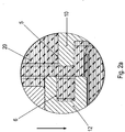
- FIG. 2a an enlarged section is shown in a first orientation in the gravitational field.
- FIG. 2b an enlarged section is shown in a second orientation in the gravitational field.
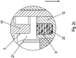
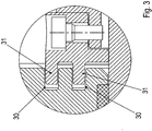
- FIG. 3 the corresponding enlarged section of a second embodiment of the invention is shown.
- FIG. 4 is shown as a further inventive embodiment, an inventive linear drive, in particular spindle drive, in a sectional view.
- FIG. 5 is an in FIG. 1 inserted intermediate ring 12 shown in an oblique view in a first viewing direction.
- the intermediate ring 12 is shown in an oblique view in a different viewing direction.
- the spindle drive on a housing part 1 which is connected on the output side with a housing part 4 and the drive side with a housing part 10, in particular bearing flange, in which a bearing 43 is accommodated, which supports the spindle 2 of the spindle drive.
- the spindle 2 is connected via a coupling with the rotor shaft of an electric motor, not shown.
- the rotor shaft is rotatably mounted in a housing of the electric motor, wherein the housing is screw-connected to the housing part 10th
- the spindle 2 can be set in rotary motion by the electric motor.
- the spindle 2 has an external thread and / or is preferably designed as a ball screw, trapezoidal threaded spindle or planetary roller spindle.
- a spindle nut 11 has an internal thread, which is in engagement with the external thread of the spindle 2.
- the spindle nut 11 is in the housing part 1 linear, ie in the axial direction, ie in the direction parallel to the axial direction of the rotor shaft of the electric motor out.
- the housing part 1 has guide grooves, in which sliding blocks, in particular made of plastic Nuts, are received, wherein the sliding blocks are connected to the spindle nut 11 or a part permanently connected to it.
- a piston rod 3 On the spindle nut 11, a piston rod 3 is fixed, which is supported in the housing part 4 by means of a sliding bearing 42.
- a scraper 41 and an axially disposed between the scraper 41 and the sliding bearing 42 seal 40 is arranged.
- a ring member 7 is screw-connected by means of axially aligned connecting screws 8.
- the screw heads of the connecting screws 8 are arranged on the end face of the connecting screws 8 facing the electric motor.
- the ring member 7 has an annular groove 6, the annular axis is aligned coaxially with the axis of the spindle 2 or the rotor shaft of the electric motor.
- the annular groove is thus open to the side facing away from the electric motor side of the electric motor.
- an intermediate ring 12 is connected to the motor-facing side of the spindle nut 11 with the spindle nut 11.
- the intermediate ring 12 covers the screw heads of the connecting screws 8.
- the intermediate ring 12 axially directed recesses 50, in which protrude the screw heads.
- the rotatably connected to the spindle nut intermediate ring 12 has an open towards the engine annular groove 9.
- annular collar formed on the housing part 10 penetrates into the annular groove 9.
- the intermediate ring 12 is connected by means of at least one radially continuous screw 44, in particular grub screw with the spindle nut 11.
- the recesses 50 are spaced apart in the circumferential direction, in particular spaced regularly from one another.
- the depressions 50 are thus arranged on the spindle nut 11 facing side of the intermediate ring 12.
- the annular groove 9 is arranged on the side facing away from the spindle nut 11 side of the intermediate ring 12.
- annular groove 9 With the spindle nut 11 on its side facing away from the engine axially an annular groove 6 and arranged on its axially facing the engine side, an annular groove 9.
- the annular groove 6 of the intermediate ring 12 is at least with their in the gravitational direction, ie in FIG. 2a indicated arrow direction, lower area completely below the oil level in the interior of the spindle drive.
- the in FIG. 2a immersed area immersed in oil 20.
- the outstanding over the oil level part of the annular groove 6 is filled with air, which is not shown.
- the spindle drive is the axial direction aligned transversely to the direction of gravity.
- the axial direction is aligned perpendicular to the direction of gravity.
- the annular groove 6 is filled with air 21, in particular completely filled with air 21, when the spindle nut retracts from above into the oil bath.
- the collar 5 moves from the oil bath in the filled with air 21 annular groove 21 a.
- the gap between the collar 5 and annular groove 6 is also sealed by oil. By means of the sealing oil in the gap, it is difficult for the compressed oil-air mixture to escape.
- the annular groove 6 is filled with oil 20 when moving out of the annular groove 6 from the oil bath.
- the collar displaced 5 when entering the annular groove 6, the oil 20, which but hardly flows out of the compressed volume through the gap between the collar 5 and groove wall.
- Advantage of this invention is also that after retraction of the respective collar in the respective annular groove of the pressure built up in the annular groove degrades by outflow of the compressed medium through the gap.
- a simple retraction is made possible without overcoming a clipping of the spindle drive. Because without the invention braking the spindle nut 11 moves to the housing part to stop and then builds up a tension between the internal thread of the spindle nut 11 and external thread of the spindle 2, which leads to a self-locking, which must be overcome during the later start.
- a first annular groove 9 is formed on the intermediate ring 12 which is connected to the spindle nut 11, in particular screw-connected, wherein the intermediate ring 12 is screwed by at least one radially through the intermediate ring 12 continuous screw with the spindle nut 11, wherein the screw in a radially directed threaded bore of the spindle nut is screwed.
- a second annular groove 6 is formed on the ring member 7, which is screw-connected to the piston rod 3, for which purpose the ring member 7 has an internal thread and the piston rod 3 has an external thread, wherein axially by a radially projecting on the spindle nut 11 annular collar continuous connecting screws in a respective axially directed threaded bore of the ring member 7 are screwed, the screw heads of the connecting screws on the side facing away from the ring member 7 side of the spindle nut 11 radially projecting annular collar abut, wherein the intermediate ring 12 circumferentially spaced recesses, in each of which Protrudes screw head.
- the piston rod 3 is supported on the housing via a plain bearing.
- the made of plastic nuts are pin-connected to the ring member 7, in particular with hollow clamping pins, and / or screw-connected and guided in a housing arranged on the axially extending longitudinal groove.
- the housing is formed from metallic housing parts 4 and 10 and the intermediate housing part 1.
- annular groove 6 and / or 9 replaced by a concentric annular groove assembly 30.
- the formed on the housing part 4 or 10 annular collar is replaced by a concentric arrangement 31 annular collars.
- the arrangements 31 and 30 of the collars are arranged such that in each case an annular collar of the arrangement 31 in one of the annular grooves of the assembly 30 is retractable.
- the ring member 7 and the spindle nut 11 are made in one piece and / or in one piece.
Description
- Die Erfindung betrifft einen Spindelantrieb mit einem Gehäuse, einer Spindel, und einer mit der Spindel in Wirkverbindung stehenden Spindelmutter.
- Es ist allgemein bekannt, dass bei einem Spindeltrieb die Spindelmutter entlang der Achse einer mit der Spindelmutter im Eingriff stehenden Spindel hin- und herbewegbar ist.
- Aus der
US 2012/2275522 A1 ist als nächstliegender Stand der Technik ein Hochlastlinearaktuator bekannt. - Aus der
EP 2 194 295 A1 ist eine elektromotorische Antriebseinheit bekannt. - Aus der
DE 20 2006 003130 U1 ist ein Linearantrieb bekannt. - Aus der
DE 10 2006 043599 A1 ist ein elektrischer Zylinder bekannt. - Der Erfindung liegt daher die Aufgabe zugrunde, einen Spindeltrieb weiterzubilden, wobei ein hartes Anschlagen an die axialen Endpositionen der Spindelmutter verhinderbar ist.
- Erfindungsgemäß wird die Aufgabe bei dem Spindeltrieb nach den in Anspruch 1 angegebenen Merkmalen gelöst.
- Wichtige Merkmale der Erfindung bei dem Spindelantrieb nach Anspruch 1 mit einem Gehäuse, einer Spindel, insbesondere Gewindespindel, Trapezgewindespindel, Kugelumlaufspindel oder Planetenrollspindel, und einer mit der Spindel in Wirkverbindung stehenden Spindelmutter,
wobei die Spindelmutter derart am Gehäuse geführt ist, dass sie bei Drehbewegung der Spindel in Spindelachsrichtung hin- oder her-bewegbar ist,
wobei die Spindelmutter zumindest an einer axialen Seite eine Ringnut aufweist oder mit einem Teil verbunden, insbesondere schraubverbunden, ist, welches eine Ringnut aufweist,
wobei am Gehäuse ein ringförmiger Kragen ausgeformt ist,
wobei der Kragen in die Ringnut eindringt oder hineinragt, wenn die Spindelmutter eine zugehörige oder entsprechende, axiale Position erreicht. - Von Vorteil ist dabei, dass ein hartes Anschlagen der Spindelmutter an den beiden axialen Endpositionen verhindert ist, weil das in der Ringnut vorhandene Medium komprimiert wird und somit der Aufschlag abgebremst wird. Das Medium ist entweder Luft, Öl oder ein Öl-Luft-Gemisch.
- Wichtige Merkmale eines erfindungsgemäßen Spindelantriebs nach Anspruch 2 sind, dass er mit einem Gehäuse, einer Spindel, insbesondere Gewindespindel, Trapezgewindespindel, Kugelumlaufspindel oder Planetenrollspindel, und einer mit der Spindel in Wirkverbindung stehenden Spindelmutter,
wobei die Spindelmutter derart am Gehäuse geführt ist, dass sie bei Drehbewegung der Spindel in Spindelachsrichtung hin- oder her-bewegbar ist,
wobei die Spindelmutter axial beidseitig jeweils eine Ringnut aufweist oder mit einem jeweiligen Teil verbunden, insbesondere schraubverbunden, ist, welches jeweils eine Ringnut aufweist,
wobei am Gehäuse jeweils ein ringförmiger Kragen ausgeformt ist,
wobei der jeweilige Kragen in die jeweilige Ringnut eindringt oder hineinragt, wenn die Spindelmutter eine jeweilige, zugehörige oder entsprechende, axiale Position erreicht. - Von Vorteil ist dabei wiederum, dass ein hartes Anschlagen der Spindelmutter an den beiden axialen Endpositionen verhindert ist, weil das in der Ringnut vorhandene Medium komprimiert wird und somit der Aufschlag abgebremst wird. Das Medium ist entweder Luft, Öl oder ein Öl-Luft-Gemisch.
- Bei einer vorteilhaften Ausgestaltung ist zwischen Ringnut und zugeordnetem Kragen ein Spalt vorgesehen bei Eindringen oder Hineinragen des jeweiligen Kragens in die jeweilige Ringnut, insbesondere wenn die Spindelmutter eine jeweilige, zugehörige oder entsprechende, axiale Position erreicht. Von Vorteil ist dabei, dass der Spalt durch Öl abgedichtet wird. Nach der Kompression strömt das komprimierte Medium durch den Spalt heraus und somit wird der Druck abgebaut.
- Bei einer vorteilhaften Ausgestaltung wird der Spalt mit Öl bedeckt und somit ein hartes Aufeinanderschlagen der Spindelmutter an den axialen Endpositionen verhindert.
- Bei einer vorteilhaften Ausgestaltung ist zumindest teilweise Öl eingefüllt im Spalt zwischen ringförmigem Kragen und der Ringnut. Von Vorteil ist dabei, dass die Ringnut zumindest teilweise gefüllt ist oder zumindest der Spalt mit Öl bedeckt ist und somit abgedichtet ist.
- Bei einer vorteilhaften Ausgestaltung ist eine erste Ringnut an einem Zwischenring ausgeformt, welches mit der Spindelmutter verbunden, insbesondere schraubverbunden, ist,
- insbesondere welches mittels zumindest einer radial durch den Zwischenring durchgehenden Schraube mit der Spindelmutter schraubverbunden ist, insbesondere wobei die Schraube in eine radial gerichtete Gewindebohrung der Spindelmutter eingeschraubt ist. Von Vorteil ist dabei, dass die Ringnut mit der Spindelmutter verbunden ist, wobei die Ringachse parallel zur Bewegungsrichtung der Spindelmutter ausgerichtet ist.
- Bei einer vorteilhaften Ausgestaltung ist eine zweite Ringnut an einem Ringteil ausgeformt, welches mit einer Kolbenstange schraubverbunden ist, insbesondere wobei hierzu das Ringteil ein Innengewinde und die Kolbenstange ein Außengewinde aufweist,
wobei axial durch einen an der Spindelmutter radial hervorstehenden ringförmigen Kragen durchgehende Verbindungsschrauben in eine jeweilige axial gerichtete Gewindebohrung des Ringteils eingeschraubt sind,
insbesondere wobei die Schraubenköpfe der Verbindungsschrauben an der von dem Ringteil abgewandten Seite des an der Spindelmutter radial hervorstehenden ringförmigen Kragens anliegen,
wobei der Zwischenring in Umfangsrichtung voneinander beabstandete Vertiefungen aufweist, in welche jeweils ein Schraubenkopf hineinragt. Von Vorteil ist dabei, dass mit der Spindelmutter axial beidseitig eine Ringnut verbunden ist, wobei die Ringnut jeweils in einem Teil vorgesehen ist, das mit der Spindelmutter verbunden ist. Ein Einarbeiten einer Nut in die Spindelmutter ist daher unnötig. - Bei einer vorteilhaften Ausgestaltung die Kolbenstange am Gehäuse über ein Gleitlager abgestützt ist. Von Vorteil ist dabei, dass eine sehr große axiale Ausdehnung der Kolbenstange und somit ein sehr großer Verfahrbereich ermöglicht ist.
- Bei einer vorteilhaften Ausgestaltung sind Nutensteine, insbesondere aus Kunststoff gefertigte Nutensteine, mit dem Ringteil schraubverbunden und in einer am Gehäuse angeordneten Nut geführt sind. Von Vorteil ist dabei, dass die Nutensteine sehr geringe Reibungsverluste bewirken, da der weiche Kunststoff der Nutensteine ein Gleitlager zum Gehäuse hin einfach realisierbar ist.
- Bei einer vorteilhaften Ausgestaltung ist das Gehäuse aus metallischen Gehäuseteilen gebildet. Von Vorteil ist dabei, dass der Spindeltrieb eine hohe Belastung aushält.
- Weitere Vorteile ergeben sich aus den Unteransprüchen. Die Erfindung ist nicht auf die Merkmalskombination der Ansprüche beschränkt. Für den Fachmann ergeben sich weitere sinnvolle Kombinationsmöglichkeiten von Ansprüchen und/oder einzelnen Anspruchsmerkmalen und/oder Merkmalen der Beschreibung und/oder der Figuren, insbesondere aus der Aufgabenstellung und/oder der sich durch Vergleich mit dem Stand der Technik stellenden Aufgabe.
- Die Erfindung wird nun anhand von Abbildungen näher erläutert:
In derFigur 1 ist als erstes erfindungsgemäßes Ausführungsbeispiel ein erfindungsgemäßer Linearantrieb, insbesondere Spindelantrieb, in Schnittansicht gezeigt. - In der
Figur 2a ist ein vergrößerter Ausschnitt in einer ersten Orientierung im Gravitationsfeld gezeigt. - In der
Figur 2b ist ein vergrößerter Ausschnitt in einer zweiten Orientierung im Gravitationsfeld gezeigt. - In der
Figur 2c ist ein vergrößerter Ausschnitt in einer dritten Orientierung im Gravitationsfeld gezeigt. - In der
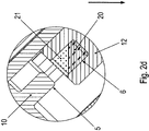
Figur 2d ist ein vergrößerter Ausschnitt in einer vierten Orientierung im Gravitationsfeld gezeigt. - In der
Figur 3 ist der entsprechende vergrößerte Ausschnitt eines zweiten erfindungsgemäßen Ausführungsbeispiels gezeigt. - In der
Figur 4 ist als weiteres erfindungsgemäßes Ausführungsbeispiel ein erfindungsgemäßer Linearantrieb, insbesondere Spindelantrieb, in Schnittansicht gezeigt. - In der
Figur 5 ist ein inFigur 1 eingesetzter Zwischenring 12 in Schrägansicht in einer ersten Blickrichtung gezeigt. - In der
Figur 6 ist der Zwischenring 12 in Schrägansicht in einer anderen Blickrichtung gezeigt. - Wie in den Figuren gezeigt, weist der Spindelantrieb ein Gehäuseteil 1 auf, welches abtriebsseitig mit einem Gehäuseteil 4 verbunden ist und antriebsseitig mit einem Gehäuseteil 10, insbesondere Lagerflansch, in welchem ein Lager 43 aufgenommen ist, welches die Spindel 2 des Spindelantriebs lagert.
- Die Spindel 2 ist über eine Kupplung mit der Rotorwelle eines nicht dargestellten Elektromotors verbunden. Die Rotorwelle ist drehbar gelagert in einem Gehäuse des Elektromotors, wobei das Gehäuse schraubverbunden ist mit dem Gehäuseteil 10.
- Somit ist die Spindel 2 vom Elektromotor in Drehbewegung versetzbar. Die Spindel 2 weist ein Außengewinde auf und/oder ist vorzugsweise als Kugelumlaufspindel, Trapezgewindespindel oder als Planetenrollspindel ausgeführt.
- Eine Spindelmutter 11 weist ein Innengewinde auf, das im Eingriff steht mit dem Außengewinde der Spindel 2. Die Spindelmutter 11 ist im Gehäuseteil 1 linear, also in axialer Richtung, also in der zur Achsrichtung der Rotorwelle des Elektromotors parallelen Richtung, geführt. Hierzu weist das Gehäuseteil 1 Führungsnuten auf, in welchen Nutensteine, insbesondere aus Kunststoff ausgeführte Nutensteine, aufgenommen sind, wobei die Nutensteine verbunden sind mit der Spindelmutter 11 oder einem mit ihr fest verbundenen Teil.
- Wenn also die Rotorwelle in Drehbewegung versetzt wird, dreht die Spindel 2 mit und somit wird die Spindelmutter 11 linear verschoben, also in axialer Richtung.
- An der Spindelmutter 11 ist eine Kolbenstange 3 befestigt, die im Gehäuseteil 4 abgestützt ist mittels eines Gleitlagers 42. Außerdem ist zwischen Kolbenstange 3 und Gehäuseteil 4 ein Abstreifer 41 und eine axial zwischen dem Abstreifer 41 und dem Gleitlager 42 angeordnete Dichtung 40 angeordnet.
- An der Spindelmutter 11 ist ein Ringteil 7 mittels axial ausgerichteter Verbindungsschrauben 8 schraubverbunden. Die Schraubenköpfe der Verbindungsschrauben 8 sind an dem dem Elektromotor zugewandten Endbereich der Verbindungsschrauben 8 angeordnet.
- Das Ringteil 7 weist eine Ringnut 6 auf, deren Ringachse koaxial zur Achse der Spindel 2 oder der Rotorwelle des Elektromotors ausgerichtet ist. Die Ringnut ist also geöffnet zu der vom Elektromotor abgewandten Seite des Elektromotors.
- Ebenso ist ein Zwischenring 12 an der zum Motor zugewandten Seite der Spindelmutter 11 mit der Spindelmutter 11 verbunden. Dabei deckt der Zwischenring 12 die Schraubenköpfe der Verbindungsschrauben 8 ab. Hierzu weist der Zwischenring 12 axial gerichtete Vertiefungen 50 auf, in welche die Schraubenköpfe hineinragen. Der mit der Spindelmutter drehfest verbundene Zwischenring 12 weist eine zum Motor hin geöffnete Ringnut 9 auf.
- Bei Anfahren der motorseitigen axialen Endposition dringt ein am Gehäuseteil 10 ausgeformter ringförmiger Kragen in die Ringnut 9 ein.
- Der Zwischenring 12 ist mittels zumindest einer radial durchgehenden Schraube 44, insbesondere Madenschraube, mit der Spindelmutter 11 verbunden.
- Die Vertiefungen 50 sind in Umfangsrichtung voneinander beabstandet, insbesondere voneinander regelmäßig beabstandet. Die Vertiefungen 50 sind also auf der der Spindelmutter 11 zugewandten Seite des Zwischenrings 12 angeordnet. Auf der von der Spindelmutter 11 abgewandten Seite des Zwischenrings 12 ist die Ringnut 9 angeordnet.
- Somit ist also mit der Spindelmutter 11 auf ihrer axial vom Motor abgewandten Seite eine Ringnut 6 und auf ihrer axial dem Motor zugewandten Seite eine Ringnut 9 angeordnet.
- An den axialen Endpositionen, also an der vom Motor weitest entfernten axialen Position und an der dem Motor nächstmöglichen axialen Position wird ein hartes Anschlagender Spindelmutter 11 und der mit ihr verbundenen Teile an das jeweilige Gehäuseteil (4, 10) verhindert, indem der am jeweiligen Gehäuseteil (4, 10) ausgeformte jeweilige ringförmige Kragen in die entsprechende Ringnut (6, 9) eintaucht.
- Wie in den
Figuren 2a ,2b ,2c ,2d dargestellt, befindet sich vor dem Auftreffen des jeweiligen ringförmigen Kragens in der jeweils entsprechenden Ringnut (6, 9) eine Ölmenge oder ein Öl-Luft-Gemisch. Dadurch wird bei Eindringen des jeweiligen Kragens in die jeweilige Ringnut (6, 9) ein Zusammenpressen der Menge oder des Gemischs bewirkt, was die Bewegung der Spindelmutter 11 bremst. Dieses Abdämpfen ist besonders effektiv ausführbar, wenn der zwischen Kragen und entsprechender Ringnut (6, 9) zugeordnete Spalt eine geringe Breite aufweist. Eine direkte Berührung der metallischen Teile, also des Kragens und der Wandung der Ringnut (6, 9) sollte aber vorzugsweise vermieden werden. - Wie in
Figur 2a gezeigt, ist die Ringnut 6 des Zwischenrings 12 zumindest mit ihrem in Gravitationsrichtung, also inFigur 2a eingezeichneter Pfeilrichtung, unteren Bereich vollständig unterhalb des Ölpegels im Innenraum des Spindeltriebs. Somit ist der inFigur 2a gezeigte Bereich in Öl 20 eingetaucht. Der über dem Ölpegel hervorragende Teil der Ringnut 6 ist mit Luft gefüllt, was nicht dargestellt ist. Beim Eindringen des Kragens 5 in die Ringnut 6 wird das weniger als die Luft kompressible Öl 20 nach oben gepresst und der Luftanteil des so in der Ringnut 6 entstehenden Öl-Luft-Gemisches komprimiert. Bei der inFigur 2a vorliegenden Einbausituation, also der Einbaulage, des Spindeltriebs ist die axiale Richtung quer zur Gravitationsrichtung ausgerichtet. Somit erfolgt auch die Bewegung der Spindelmutter 11 in dieser Richtung, also quer zur Gravitationsrichtung. Der Spalt zwischen Kragen 5 und Ringnut 6 wird auch durch Öl etwas abgedichtet. Mittels des im Spalt sich befindenden abdichtenden Öls ist es dem komprimierten Öl-Luft-Gemisch erschwert zu entweichen. - Wie in
Figur 2b gezeigt, ist hier die axiale Richtung senkrecht zur Gravitationsrichtung ausgerichtet. Somit ist die Ringnut 6 mit Luft 21 gefüllt, insbesondere vollständig mit Luft 21 gefüllt, wenn die Spindelmutter von oben ins Ölbad einfährt. Somit fährt der Kragen 5 aus dem Ölbad in die mit Luft 21 gefüllte Ringnut 21 ein. Der Spalt zwischen Kragen 5 und Ringnut 6 wird auch durch Öl abgedichtet. Mittels des im Spalt sich befindenden abdichtenden Öls wird es dem komprimierten Öl-Luft-Gemisch erschwert zu entweichen. - Wie in
Figur 2c gezeigt, ist beim Herausfahren der Ringnut 6 aus dem Ölbad die Ringnut 6 mit Öl 20 gefüllt. Dabei verdrängt der Kragen 5 beim Einfahren in die Ringnut 6 das Öl 20, welches aber nur schwerlich aus dem komprimierten Volumen durch den Spalt zwischen Kragen 5 und Nutwandung herausströmt. - Wie in
Figur 2d gezeigt, ist bei zur Gravitationsrichtung gewinkelter Ausrichtung des Spindeltriebs, wobei die axiale Richtung einen Winkel zwischen 0° und 90° aufweist, beispielsweise einen Winkel von 45°, nur ein Teil des unteren Teils der Ringnut 6 mit Öl 20 gefüllt. - Somit wird in den in den
Figuren 2a ,2b ,2c ,2d gezeigten Ausrichtungen des Spindeltriebs jeweils Öl, Luft und/oder ein Öl-Luft-Gemisch komprimiert und somit der Spindeltrieb 11 abgebremst. - Da axial beidseitig am Spindeltrieb 11 eine Ringnut angeordnet ist, ist das vorgenannte Abbremsen axial beidseitig mit dem jeweils entsprechenden Kragen des Gehäuseteils 4 oder 10 ausführbar.
- Vorteil dieser Erfindung ist auch, dass nach Einfahren des jeweiligen Kragens in die jeweilige Ringnut der aufgebaute Druck in der Ringnut sich durch Ausströmen des komprimierten Mediums durch den Spalt abbaut. Somit ist ein einfaches Herausfahren ermöglicht, ohne Überwinden eines Festfahrens des Spindeltriebs. Denn ohne das erfindungsgemäße Abbremsen fährt die Spindelmutter 11 ans Gehäuseteil auf Anschlag und danach baut sich noch eine Verspannung zwischen Innengewinde der Spindelmutter 11 und Außengewinde der Spindel 2 auf, die zu einer Selbsthemmung führt, welche beim späteren Losfahren überwunden werden muss.
- Wie in
Figur 4 gezeigt, ist eine erste Ringnut 9 an dem Zwischenring 12 ausgeformt, welcher mit der Spindelmutter 11 verbunden, insbesondere schraubverbunden, ist, wobei der Zwischenring 12 mittels zumindest einer radial durch den Zwischenring 12 durchgehenden Schraube mit der Spindelmutter 11 schraubverbunden ist, wobei die Schraube in eine radial gerichtete Gewindebohrung der Spindelmutter eingeschraubt ist. - Dabei ist eine zweite Ringnut 6 an dem Ringteil 7 ausgeformt, welches mit der Kolbenstange 3 schraubverbunden ist, wobei hierzu das Ringteil 7 ein Innengewinde und die Kolbenstange 3 ein Außengewinde aufweist, wobei axial durch einen an der Spindelmutter 11 radial hervorstehenden ringförmigen Kragen durchgehende Verbindungsschrauben in eine jeweilige axial gerichtete Gewindebohrung des Ringteils 7 eingeschraubt sind, wobei die Schraubenköpfe der Verbindungsschrauben an der von dem Ringteil 7 abgewandten Seite des an der Spindelmutter 11 radial hervorstehenden ringförmigen Kragens anliegen, wobei der Zwischenring 12 in Umfangsrichtung voneinander beabstandete Vertiefungen aufweist, in welche jeweils ein Schraubenkopf hineinragt.
- Die Kolbenstange 3 ist am Gehäuse über ein Gleitlager abgestützt.
- Die aus Kunststoff gefertigten Nutensteine sind mit dem Ringteil 7 stiftverbunden, insbesondere mit Hohlspannstiften, und/oder schraubverbunden und in einer am Gehäuse angeordneten axial sich erstreckenden Längsnut geführt.
- Das Gehäuse ist aus metallischen Gehäuseteilen 4 und 10 sowie dem zwischengeordneten Gehäuseteil 1 gebildet.
- Wie in
Figur 3 gezeigt, wird bei einem weiteren erfindungsgemäßen Ausführungsbeispiel die Ringnut 6 und/oder 9 ersetzt durch eine konzentrische Ringnutanordnung 30. Entsprechend wird der am Gehäuseteil 4 oder 10 ausgeformte ringförmige Kragen durch eine konzentrische Anordnung 31 ringförmiger Krägen ersetzt. Auf diese Weise ist ein noch weiter verstärktes Abbremsen erreichbar. Die Anordnungen 31 und 30 der Krägen sind dabei derart angeordnet, dass jeweils ein ringförmiger Kragen der Anordnung 31 in eine der Ringnuten der Anordnung 30 einfahrbar ist. - Bei einem weiteren erfindungsgemäßen Ausführungsbeispiel sind das Ringteil 7 und die Spindelmutter 11 einstückig und/oder einteilig ausgeführt.
-
- 1 Gehäuseteil
- 2 Spindel
- 3 Kolbenstange
- 4 Gehäuseteil
- 5 ringförmiger Kragen am Gehäuseteil 4
- 6 Ringnut an Ringteil 7
- 7 Ringteil
- 8 Verbindungsschraube
- 9 Ringnut am Zwischenring 12
- 10 Gehäuseteil, insbesondere Lagerflansch
- 11 Spindelmutter
- 12 Zwischenring
- 20 Öl
- 21 Luft
- 30 konzentrische Ringnutanordnung
- 31 konzentrische Anordnung ringförmiger Kragen
- 40 Dichtung
- 41 Abstreifer
- 42 Gleitlager
- 43 Lager
- 50 Vertiefung
Claims (9)
- Spindelantrieb mit einem Gehäuse, einer Spindel (2), insbesondere Gewindespindel, Trapezgewindespindel, Kugelumlaufspindel oder Planetenrollspindel, und einer mit der Spindel (2) in Wirkverbindung stehenden Spindelmutter (11),
wobei die Spindelmutter (11) derart am Gehäuse geführt ist, dass sie bei Drehbewegung der Spindel (2) in Spindelachsrichtung hin- oder her-bewegbar ist,
dadurch gekennzeichnet, dass
die Spindelmutter (11) zumindest an einer axialen Seite eine Ringnut (9) aufweist oder mit einem Teil verbunden, insbesondere schraubverbunden, ist, welches eine Ringnut (9) aufweist,
wobei am Gehäuse ein ringförmiger Kragen (5) ausgeformt ist,
wobei der Kragen (5) in die Ringnut (9) eindringt oder hineinragt, wenn die Spindelmutter (11) eine zugehörige oder entsprechende, axiale Position erreicht. - Spindelantrieb nach Anspruch 1,
dadurch gekennzeichnet, dass
die Spindelmutter (11) axial beidseitig jeweils eine Ringnut (9) aufweist oder mit einem jeweiligen Teil verbunden, insbesondere schraubverbunden, ist, welches jeweils eine Ringnut (9) aufweist. - Spindelantrieb nach Anspruch 1 oder 2,
dadurch gekennzeichnet, dass
zwischen Ringnut (9) und zugeordnetem Kragen (5) ein Spalt vorgesehen ist bei Eindringen oder Hineinragen des jeweiligen Kragens (5) in die jeweilige Ringnut (9), insbesondere wenn die Spindelmutter (11) eine jeweilige, zugehörige oder entsprechende, axiale Position erreicht. - Spindelantrieb nach mindestens einem der vorangegangenen Ansprüche,
dadurch gekennzeichnet, dass
das Gehäuse einen Innenraum umgibt, in welchem die Spindelmutter (11) angeordnet ist und in welchem zumindest teilweise Öl (20) eingefüllt ist. - Spindelantrieb nach mindestens einem der vorangegangenen Ansprüche,
dadurch gekennzeichnet, dass
eine erste Ringnut (9) an einem Zwischenring (12) ausgeformt ist, welcher mit der Spindelmutter (11) verbunden, insbesondere schraubverbunden, ist, insbesondere welcher mittels zumindest einer radial durch den Zwischenring (12) durchgehenden Schraube mit der Spindelmutter (11) schraubverbunden ist, insbesondere wobei die Schraube in eine radial gerichtete Gewindebohrung der Spindelmutter (11) eingeschraubt ist. - Spindelantrieb nach mindestens einem der vorangegangenen Ansprüche,
dadurch gekennzeichnet, dass
eine zweite Ringnut (6) an einem Ringteil (7) ausgeformt ist, welches mit einer Kolbenstange (3) schraubverbunden ist, insbesondere wobei hierzu das Ringteil (7) ein Innengewinde und die Kolbenstange (3) ein Außengewinde aufweist,
wobei axial durch einen an der Spindelmutter (11) radial hervorstehenden ringförmigen Kragen (5) durchgehende Verbindungsschrauben (8) in eine jeweilige axial gerichtete Gewindebohrung des Ringteils (7) eingeschraubt sind,
insbesondere wobei die Schraubenköpfe der Verbindungsschrauben (8) an der von dem Ringteil (7) abgewandten Seite des an der Spindelmutter (11) radial hervorstehenden ringförmigen Kragens (5) anliegen,
wobei der Zwischenring (12) in Umfangsrichtung voneinander beabstandete Vertiefungen (50) aufweist, in welche jeweils ein Schraubenkopf hineinragt. - Spindelantrieb nach mindestens einem der vorangegangenen Ansprüche,
dadurch gekennzeichnet, dass
die Kolbenstange (3) am Gehäuse über ein Gleitlager (42) abgestützt ist. - Spindelantrieb nach mindestens einem der vorangegangenen Ansprüche,
dadurch gekennzeichnet, dass
Nutensteine, insbesondere aus Kunststoff gefertigte Nutensteine, mit dem Ringteil (7) stiftverbunden, insbesondere mit Hohlspannstiften, und/oder schraubverbunden sind und in einer am Gehäuse angeordneten Nut geführt sind. - Spindelantrieb nach mindestens einem der vorangegangenen Ansprüche,
dadurch gekennzeichnet, dass
das Gehäuse aus metallischen Gehäuseteilen (1, 4) gebildet ist.
Applications Claiming Priority (3)
| Application Number | Priority Date | Filing Date | Title |
|---|---|---|---|
| DE102014018919 | 2014-12-22 | ||
| DE102015000358.5A DE102015000358B3 (de) | 2014-12-22 | 2015-01-20 | Spindelantrieb mit einem Gehäuse, einer Spindel, und einer mit der Spindel in Wirkverbindung stehenden Spindelmutter |
| PCT/EP2015/002310 WO2016102036A1 (de) | 2014-12-22 | 2015-11-18 | Spindelantrieb mit einem gehäuse, einer spindel, und einer mit der spindel in wirkverbindung stehenden spindelmutter |
Publications (2)
| Publication Number | Publication Date |
|---|---|
| EP3237779A1 EP3237779A1 (de) | 2017-11-01 |
| EP3237779B1 true EP3237779B1 (de) | 2019-01-09 |
Family
ID=55135075
Family Applications (1)
| Application Number | Title | Priority Date | Filing Date |
|---|---|---|---|
| EP15812949.4A Active EP3237779B1 (de) | 2014-12-22 | 2015-11-18 | Spindelantrieb mit einem gehäuse, einer spindel, und einer mit der spindel in wirkverbindung stehenden spindelmutter |
Country Status (5)
| Country | Link |
|---|---|
| US (1) | US10808812B2 (de) |
| EP (1) | EP3237779B1 (de) |
| CN (1) | CN107110313B (de) |
| DE (1) | DE102015000358B3 (de) |
| WO (1) | WO2016102036A1 (de) |
Family Cites Families (10)
| Publication number | Priority date | Publication date | Assignee | Title |
|---|---|---|---|---|
| US2631709A (en) * | 1949-05-02 | 1953-03-17 | Boeing Co | Limit stop mechanism |
| GB881194A (en) * | 1958-01-18 | 1961-11-01 | Garringtons Ltd | Improvements relating to shock absorbers |
| WO2006089554A1 (en) | 2005-02-26 | 2006-08-31 | Linak A/S | A linear actuator |
| JP2007089275A (ja) | 2005-09-21 | 2007-04-05 | Smc Corp | 電動シリンダ |
| DE202009013875U1 (de) * | 2008-10-29 | 2009-12-17 | Sumitomo (Shi) Demag Plastics Machinery Gmbh | Spindelanordnung zur Relativverstellung eines Maschinenelements zu einer Spindel |
| ATE551557T1 (de) * | 2008-12-08 | 2012-04-15 | Schaeffler Technologies Ag | Elektromotorische antriebseinheit |
| US8733192B2 (en) * | 2011-03-11 | 2014-05-27 | Timotion Technology Co., Ltd. | High-load linear actuator |
| TWI516696B (zh) | 2013-05-03 | 2016-01-11 | Timotion Technology Co Ltd | Electric cylinder with cushioning structure |
| CN203926710U (zh) | 2014-07-04 | 2014-11-05 | 第一传动科技股份有限公司 | 线性致动装置及其缓冲机构 |
| DE102014224259A1 (de) * | 2014-11-27 | 2016-06-02 | Robert Bosch Gmbh | Linearaktuator |
-
2015
- 2015-01-20 DE DE102015000358.5A patent/DE102015000358B3/de active Active
- 2015-11-18 US US15/538,522 patent/US10808812B2/en active Active
- 2015-11-18 CN CN201580062267.6A patent/CN107110313B/zh active Active
- 2015-11-18 WO PCT/EP2015/002310 patent/WO2016102036A1/de active Application Filing
- 2015-11-18 EP EP15812949.4A patent/EP3237779B1/de active Active
Non-Patent Citations (1)
| Title |
|---|
| None * |
Also Published As
| Publication number | Publication date |
|---|---|
| DE102015000358B3 (de) | 2016-02-11 |
| WO2016102036A1 (de) | 2016-06-30 |
| CN107110313B (zh) | 2019-11-29 |
| US20170350478A1 (en) | 2017-12-07 |
| EP3237779A1 (de) | 2017-11-01 |
| US10808812B2 (en) | 2020-10-20 |
| CN107110313A (zh) | 2017-08-29 |
Similar Documents
| Publication | Publication Date | Title |
|---|---|---|
| DE102007043391A1 (de) | Aktuator mit verlagerbarem Ausleger | |
| EP3189235B1 (de) | Exzenterschneckenpumpe | |
| DE102016124117B4 (de) | Türkomponente mit einem steuerbaren Drehdämpfer | |
| WO2010089073A1 (de) | Spindelmotor | |
| EP2715188A1 (de) | Welle mit einem lager | |
| EP3417183B1 (de) | Kugelgelenk | |
| DE102016124115B4 (de) | Drehdämpfer | |
| DE102013214733A1 (de) | Linearantrieb | |
| EP1170518B1 (de) | Verriegelbare Lagereinheit | |
| DE102006060681B3 (de) | Dichtung für Gewindetrieb | |
| DE102009007952B4 (de) | Spindelmotor | |
| EP2891824B1 (de) | Schieber | |
| DE102013215259B4 (de) | Radialflexibles Wälzlager | |
| EP2707629B1 (de) | Vorrichtung zum abdichten eines pumpraums einer drehkolbenpumpe, sowie drehkolbenpumpe mit selbiger | |
| DE102015211477B4 (de) | Hydrostatischer Kupplungsaktor | |
| EP3237779B1 (de) | Spindelantrieb mit einem gehäuse, einer spindel, und einer mit der spindel in wirkverbindung stehenden spindelmutter | |
| EP1496600A2 (de) | Linearantrieb | |
| EP3106698A1 (de) | Mechanisches getriebe mit integrierter lastmomentsperre | |
| DE102012214552A1 (de) | Mutter-Spindel-Vorrichtung und Aktorik für ein Getriebe einer Kurbelwellenriemenscheibe | |
| EP2826946B1 (de) | Spindelsperre für Jalousien | |
| DE102013014421B4 (de) | Formschlüssige drehstellungsunabhängige Schaltkupplung mit hydraulischer oder pneumatischer Betätigung | |
| DE102019214037A1 (de) | Druckbereitstellungseinrichtung | |
| EP3927997A1 (de) | Kugelgewindetrieb mit verdrehsicherung | |
| DE102014224499A1 (de) | Elektrozylinder mit Verdrehsicherung über Laufrollen | |
| DE102013102841A1 (de) | Selbstreinigender Spindelantrieb |
Legal Events
| Date | Code | Title | Description |
|---|---|---|---|
| STAA | Information on the status of an ep patent application or granted ep patent |
Free format text: STATUS: THE INTERNATIONAL PUBLICATION HAS BEEN MADE |
|
| PUAI | Public reference made under article 153(3) epc to a published international application that has entered the european phase |
Free format text: ORIGINAL CODE: 0009012 |
|
| STAA | Information on the status of an ep patent application or granted ep patent |
Free format text: STATUS: REQUEST FOR EXAMINATION WAS MADE |
|
| 17P | Request for examination filed |
Effective date: 20170724 |
|
| AK | Designated contracting states |
Kind code of ref document: A1 Designated state(s): AL AT BE BG CH CY CZ DE DK EE ES FI FR GB GR HR HU IE IS IT LI LT LU LV MC MK MT NL NO PL PT RO RS SE SI SK SM TR |
|
| AX | Request for extension of the european patent |
Extension state: BA ME |
|
| DAV | Request for validation of the european patent (deleted) | ||
| DAX | Request for extension of the european patent (deleted) | ||
| REG | Reference to a national code |
Ref country code: DE Ref legal event code: R079 Ref document number: 502015007667 Country of ref document: DE Free format text: PREVIOUS MAIN CLASS: F16H0025200000 Ipc: F16H0057040000 |
|
| RIC1 | Information provided on ipc code assigned before grant |
Ipc: F16H 57/04 20100101AFI20180606BHEP Ipc: F16H 25/20 20060101ALI20180606BHEP |
|
| GRAP | Despatch of communication of intention to grant a patent |
Free format text: ORIGINAL CODE: EPIDOSNIGR1 |
|
| STAA | Information on the status of an ep patent application or granted ep patent |
Free format text: STATUS: GRANT OF PATENT IS INTENDED |
|
| INTG | Intention to grant announced |
Effective date: 20180726 |
|
| GRAS | Grant fee paid |
Free format text: ORIGINAL CODE: EPIDOSNIGR3 |
|
| GRAA | (expected) grant |
Free format text: ORIGINAL CODE: 0009210 |
|
| STAA | Information on the status of an ep patent application or granted ep patent |
Free format text: STATUS: THE PATENT HAS BEEN GRANTED |
|
| AK | Designated contracting states |
Kind code of ref document: B1 Designated state(s): AL AT BE BG CH CY CZ DE DK EE ES FI FR GB GR HR HU IE IS IT LI LT LU LV MC MK MT NL NO PL PT RO RS SE SI SK SM TR |
|
| REG | Reference to a national code |
Ref country code: GB Ref legal event code: FG4D Free format text: NOT ENGLISH |
|
| REG | Reference to a national code |
Ref country code: CH Ref legal event code: EP Ref country code: AT Ref legal event code: REF Ref document number: 1087708 Country of ref document: AT Kind code of ref document: T Effective date: 20190115 |
|
| REG | Reference to a national code |
Ref country code: DE Ref legal event code: R096 Ref document number: 502015007667 Country of ref document: DE |
|
| REG | Reference to a national code |
Ref country code: IE Ref legal event code: FG4D Free format text: LANGUAGE OF EP DOCUMENT: GERMAN |
|
| REG | Reference to a national code |
Ref country code: CH Ref legal event code: NV Representative=s name: HEPP WENGER RYFFEL AG, CH |
|
| REG | Reference to a national code |
Ref country code: NL Ref legal event code: FP |
|
| REG | Reference to a national code |
Ref country code: LT Ref legal event code: MG4D |
|
| PG25 | Lapsed in a contracting state [announced via postgrant information from national office to epo] |
Ref country code: ES Free format text: LAPSE BECAUSE OF FAILURE TO SUBMIT A TRANSLATION OF THE DESCRIPTION OR TO PAY THE FEE WITHIN THE PRESCRIBED TIME-LIMIT Effective date: 20190109 Ref country code: SE Free format text: LAPSE BECAUSE OF FAILURE TO SUBMIT A TRANSLATION OF THE DESCRIPTION OR TO PAY THE FEE WITHIN THE PRESCRIBED TIME-LIMIT Effective date: 20190109 Ref country code: PT Free format text: LAPSE BECAUSE OF FAILURE TO SUBMIT A TRANSLATION OF THE DESCRIPTION OR TO PAY THE FEE WITHIN THE PRESCRIBED TIME-LIMIT Effective date: 20190509 Ref country code: LT Free format text: LAPSE BECAUSE OF FAILURE TO SUBMIT A TRANSLATION OF THE DESCRIPTION OR TO PAY THE FEE WITHIN THE PRESCRIBED TIME-LIMIT Effective date: 20190109 Ref country code: PL Free format text: LAPSE BECAUSE OF FAILURE TO SUBMIT A TRANSLATION OF THE DESCRIPTION OR TO PAY THE FEE WITHIN THE PRESCRIBED TIME-LIMIT Effective date: 20190109 Ref country code: FI Free format text: LAPSE BECAUSE OF FAILURE TO SUBMIT A TRANSLATION OF THE DESCRIPTION OR TO PAY THE FEE WITHIN THE PRESCRIBED TIME-LIMIT Effective date: 20190109 Ref country code: NO Free format text: LAPSE BECAUSE OF FAILURE TO SUBMIT A TRANSLATION OF THE DESCRIPTION OR TO PAY THE FEE WITHIN THE PRESCRIBED TIME-LIMIT Effective date: 20190409 |
|
| PG25 | Lapsed in a contracting state [announced via postgrant information from national office to epo] |
Ref country code: BG Free format text: LAPSE BECAUSE OF FAILURE TO SUBMIT A TRANSLATION OF THE DESCRIPTION OR TO PAY THE FEE WITHIN THE PRESCRIBED TIME-LIMIT Effective date: 20190409 Ref country code: IS Free format text: LAPSE BECAUSE OF FAILURE TO SUBMIT A TRANSLATION OF THE DESCRIPTION OR TO PAY THE FEE WITHIN THE PRESCRIBED TIME-LIMIT Effective date: 20190509 Ref country code: RS Free format text: LAPSE BECAUSE OF FAILURE TO SUBMIT A TRANSLATION OF THE DESCRIPTION OR TO PAY THE FEE WITHIN THE PRESCRIBED TIME-LIMIT Effective date: 20190109 Ref country code: GR Free format text: LAPSE BECAUSE OF FAILURE TO SUBMIT A TRANSLATION OF THE DESCRIPTION OR TO PAY THE FEE WITHIN THE PRESCRIBED TIME-LIMIT Effective date: 20190410 Ref country code: LV Free format text: LAPSE BECAUSE OF FAILURE TO SUBMIT A TRANSLATION OF THE DESCRIPTION OR TO PAY THE FEE WITHIN THE PRESCRIBED TIME-LIMIT Effective date: 20190109 Ref country code: HR Free format text: LAPSE BECAUSE OF FAILURE TO SUBMIT A TRANSLATION OF THE DESCRIPTION OR TO PAY THE FEE WITHIN THE PRESCRIBED TIME-LIMIT Effective date: 20190109 |
|
| REG | Reference to a national code |
Ref country code: DE Ref legal event code: R097 Ref document number: 502015007667 Country of ref document: DE |
|
| PG25 | Lapsed in a contracting state [announced via postgrant information from national office to epo] |
Ref country code: RO Free format text: LAPSE BECAUSE OF FAILURE TO SUBMIT A TRANSLATION OF THE DESCRIPTION OR TO PAY THE FEE WITHIN THE PRESCRIBED TIME-LIMIT Effective date: 20190109 Ref country code: SK Free format text: LAPSE BECAUSE OF FAILURE TO SUBMIT A TRANSLATION OF THE DESCRIPTION OR TO PAY THE FEE WITHIN THE PRESCRIBED TIME-LIMIT Effective date: 20190109 Ref country code: AL Free format text: LAPSE BECAUSE OF FAILURE TO SUBMIT A TRANSLATION OF THE DESCRIPTION OR TO PAY THE FEE WITHIN THE PRESCRIBED TIME-LIMIT Effective date: 20190109 Ref country code: DK Free format text: LAPSE BECAUSE OF FAILURE TO SUBMIT A TRANSLATION OF THE DESCRIPTION OR TO PAY THE FEE WITHIN THE PRESCRIBED TIME-LIMIT Effective date: 20190109 Ref country code: EE Free format text: LAPSE BECAUSE OF FAILURE TO SUBMIT A TRANSLATION OF THE DESCRIPTION OR TO PAY THE FEE WITHIN THE PRESCRIBED TIME-LIMIT Effective date: 20190109 Ref country code: CZ Free format text: LAPSE BECAUSE OF FAILURE TO SUBMIT A TRANSLATION OF THE DESCRIPTION OR TO PAY THE FEE WITHIN THE PRESCRIBED TIME-LIMIT Effective date: 20190109 |
|
| PLBE | No opposition filed within time limit |
Free format text: ORIGINAL CODE: 0009261 |
|
| STAA | Information on the status of an ep patent application or granted ep patent |
Free format text: STATUS: NO OPPOSITION FILED WITHIN TIME LIMIT |
|
| PG25 | Lapsed in a contracting state [announced via postgrant information from national office to epo] |
Ref country code: SM Free format text: LAPSE BECAUSE OF FAILURE TO SUBMIT A TRANSLATION OF THE DESCRIPTION OR TO PAY THE FEE WITHIN THE PRESCRIBED TIME-LIMIT Effective date: 20190109 |
|
| 26N | No opposition filed |
Effective date: 20191010 |
|
| PG25 | Lapsed in a contracting state [announced via postgrant information from national office to epo] |
Ref country code: SI Free format text: LAPSE BECAUSE OF FAILURE TO SUBMIT A TRANSLATION OF THE DESCRIPTION OR TO PAY THE FEE WITHIN THE PRESCRIBED TIME-LIMIT Effective date: 20190109 |
|
| PG25 | Lapsed in a contracting state [announced via postgrant information from national office to epo] |
Ref country code: TR Free format text: LAPSE BECAUSE OF FAILURE TO SUBMIT A TRANSLATION OF THE DESCRIPTION OR TO PAY THE FEE WITHIN THE PRESCRIBED TIME-LIMIT Effective date: 20190109 |
|
| PG25 | Lapsed in a contracting state [announced via postgrant information from national office to epo] |
Ref country code: LU Free format text: LAPSE BECAUSE OF NON-PAYMENT OF DUE FEES Effective date: 20191118 Ref country code: MC Free format text: LAPSE BECAUSE OF FAILURE TO SUBMIT A TRANSLATION OF THE DESCRIPTION OR TO PAY THE FEE WITHIN THE PRESCRIBED TIME-LIMIT Effective date: 20190109 |
|
| REG | Reference to a national code |
Ref country code: BE Ref legal event code: MM Effective date: 20191130 |
|
| PG25 | Lapsed in a contracting state [announced via postgrant information from national office to epo] |
Ref country code: IE Free format text: LAPSE BECAUSE OF NON-PAYMENT OF DUE FEES Effective date: 20191118 |
|
| PG25 | Lapsed in a contracting state [announced via postgrant information from national office to epo] |
Ref country code: BE Free format text: LAPSE BECAUSE OF NON-PAYMENT OF DUE FEES Effective date: 20191130 |
|
| PG25 | Lapsed in a contracting state [announced via postgrant information from national office to epo] |
Ref country code: CY Free format text: LAPSE BECAUSE OF FAILURE TO SUBMIT A TRANSLATION OF THE DESCRIPTION OR TO PAY THE FEE WITHIN THE PRESCRIBED TIME-LIMIT Effective date: 20190109 |
|
| PG25 | Lapsed in a contracting state [announced via postgrant information from national office to epo] |
Ref country code: HU Free format text: LAPSE BECAUSE OF FAILURE TO SUBMIT A TRANSLATION OF THE DESCRIPTION OR TO PAY THE FEE WITHIN THE PRESCRIBED TIME-LIMIT; INVALID AB INITIO Effective date: 20151118 Ref country code: MT Free format text: LAPSE BECAUSE OF FAILURE TO SUBMIT A TRANSLATION OF THE DESCRIPTION OR TO PAY THE FEE WITHIN THE PRESCRIBED TIME-LIMIT Effective date: 20190109 |
|
| PG25 | Lapsed in a contracting state [announced via postgrant information from national office to epo] |
Ref country code: MK Free format text: LAPSE BECAUSE OF FAILURE TO SUBMIT A TRANSLATION OF THE DESCRIPTION OR TO PAY THE FEE WITHIN THE PRESCRIBED TIME-LIMIT Effective date: 20190109 |
|
| PGFP | Annual fee paid to national office [announced via postgrant information from national office to epo] |
Ref country code: NL Payment date: 20231016 Year of fee payment: 9 Ref country code: FR Payment date: 20230929 Year of fee payment: 9 |
|
| PGFP | Annual fee paid to national office [announced via postgrant information from national office to epo] |
Ref country code: GB Payment date: 20231006 Year of fee payment: 9 |
|
| PGFP | Annual fee paid to national office [announced via postgrant information from national office to epo] |
Ref country code: IT Payment date: 20231010 Year of fee payment: 9 Ref country code: DE Payment date: 20231130 Year of fee payment: 9 Ref country code: CH Payment date: 20231214 Year of fee payment: 9 Ref country code: AT Payment date: 20231103 Year of fee payment: 9 |