EP3237779B1 - Transmission à vis avec un boîtier, une vis et un écrou en connexion avec la vis - Google Patents
Transmission à vis avec un boîtier, une vis et un écrou en connexion avec la vis Download PDFInfo
- Publication number
- EP3237779B1 EP3237779B1 EP15812949.4A EP15812949A EP3237779B1 EP 3237779 B1 EP3237779 B1 EP 3237779B1 EP 15812949 A EP15812949 A EP 15812949A EP 3237779 B1 EP3237779 B1 EP 3237779B1
- Authority
- EP
- European Patent Office
- Prior art keywords
- spindle
- annular groove
- screw
- spindle nut
- housing
- Prior art date
- Legal status (The legal status is an assumption and is not a legal conclusion. Google has not performed a legal analysis and makes no representation as to the accuracy of the status listed.)
- Active
Links
- 230000005540 biological transmission Effects 0.000 title 1
- 230000003993 interaction Effects 0.000 title 1
- 229920003023 plastic Polymers 0.000 claims description 5
- 239000004033 plastic Substances 0.000 claims description 5
- 238000007373 indentation Methods 0.000 claims 1
- 239000000463 material Substances 0.000 claims 1
- 230000002093 peripheral effect Effects 0.000 claims 1
- 239000000203 mixture Substances 0.000 description 8
- 230000005484 gravity Effects 0.000 description 4
- 230000006835 compression Effects 0.000 description 2
- 238000007906 compression Methods 0.000 description 2
- 238000009434 installation Methods 0.000 description 2
- 230000035515 penetration Effects 0.000 description 2
- 238000007789 sealing Methods 0.000 description 2
- 230000008878 coupling Effects 0.000 description 1
- 238000010168 coupling process Methods 0.000 description 1
- 238000005859 coupling reaction Methods 0.000 description 1
- 238000013016 damping Methods 0.000 description 1
- 238000010348 incorporation Methods 0.000 description 1
Images


Classifications
-
- F—MECHANICAL ENGINEERING; LIGHTING; HEATING; WEAPONS; BLASTING
- F16—ENGINEERING ELEMENTS AND UNITS; GENERAL MEASURES FOR PRODUCING AND MAINTAINING EFFECTIVE FUNCTIONING OF MACHINES OR INSTALLATIONS; THERMAL INSULATION IN GENERAL
- F16H—GEARING
- F16H25/00—Gearings comprising primarily only cams, cam-followers and screw-and-nut mechanisms
- F16H25/18—Gearings comprising primarily only cams, cam-followers and screw-and-nut mechanisms for conveying or interconverting oscillating or reciprocating motions
- F16H25/20—Screw mechanisms
- F16H25/2015—Means specially adapted for stopping actuators in the end position; Position sensing means
-
- F—MECHANICAL ENGINEERING; LIGHTING; HEATING; WEAPONS; BLASTING
- F16—ENGINEERING ELEMENTS AND UNITS; GENERAL MEASURES FOR PRODUCING AND MAINTAINING EFFECTIVE FUNCTIONING OF MACHINES OR INSTALLATIONS; THERMAL INSULATION IN GENERAL
- F16H—GEARING
- F16H57/00—General details of gearing
- F16H57/04—Features relating to lubrication or cooling or heating
- F16H57/048—Type of gearings to be lubricated, cooled or heated
- F16H57/0497—Screw mechanisms
-
- F—MECHANICAL ENGINEERING; LIGHTING; HEATING; WEAPONS; BLASTING
- F16—ENGINEERING ELEMENTS AND UNITS; GENERAL MEASURES FOR PRODUCING AND MAINTAINING EFFECTIVE FUNCTIONING OF MACHINES OR INSTALLATIONS; THERMAL INSULATION IN GENERAL
- F16H—GEARING
- F16H25/00—Gearings comprising primarily only cams, cam-followers and screw-and-nut mechanisms
- F16H25/18—Gearings comprising primarily only cams, cam-followers and screw-and-nut mechanisms for conveying or interconverting oscillating or reciprocating motions
- F16H25/20—Screw mechanisms
- F16H2025/204—Axial sliding means, i.e. for rotary support and axial guiding of nut or screw shaft
Definitions
- the invention relates to a spindle drive with a housing, a spindle, and a spindle nut operatively connected to the spindle.
- the spindle nut is reciprocable along the axis of a spindle engaged with the spindle nut.
- the invention is therefore the object of developing a spindle drive, wherein a hard abutment against the axial end positions of the spindle nut can be prevented.
- the object is achieved in the spindle drive according to the features specified in claim 1.
- spindle drive with a housing, a spindle, in particular threaded spindle, trapezoidal threaded spindle, ball screw or planetary roller spindle, and a standing with the spindle in operative connection spindle nut, wherein the spindle nut is guided on the housing in such a way that it can be moved back and forth in the spindle axis direction during rotational movement of the spindle, wherein the spindle nut has an annular groove on at least one axial side or is connected to a part, in particular screw-connected, which has an annular groove, wherein on the housing an annular collar is formed, wherein the collar penetrates or protrudes into the annular groove when the spindle nut reaches an associated or corresponding axial position.
- the advantage here is that a hard abutment of the spindle nut is prevented at the two axial end positions, because the medium present in the annular groove is compressed and thus the impact is slowed down.
- the medium is either air, oil or an oil-air mixture.
- a spindle drive according to the invention according to claim 2, that it with a housing, a spindle, in particular threaded spindle, trapezoidal threaded spindle, ball screw or planetary roller spindle, and a standing with the spindle operatively connected spindle nut, wherein the spindle nut is guided on the housing in such a way that it can be moved back and forth in the spindle axis direction during rotational movement of the spindle, wherein the spindle nut axially on both sides each having an annular groove or connected to a respective part, in particular screw-connected, which in each case has an annular groove, wherein on the housing in each case an annular collar is formed, wherein the respective collar penetrates or protrudes into the respective annular groove when the spindle nut reaches a respective, corresponding or corresponding, axial position.
- the advantage here is again that a hard abutment of the spindle nut is prevented at the two axial end positions, because the medium present in the annular groove is compressed and thus the impact is slowed down.
- the medium is either air, oil or an oil-air mixture.
- a gap is provided between the annular groove and associated collar upon penetration or intrusion of the respective collar in the respective annular groove, in particular when the spindle nut reaches a respective, corresponding or corresponding, axial position.
- the advantage here is that the gap is sealed by oil. After compression, the compressed medium flows out through the gap and thus the pressure is released.
- the gap is covered with oil and thus prevents a hard Aufrely the spindle nut at the axial end positions.
- oil is at least partially filled in the gap between the annular collar and the annular groove.
- the advantage here is that the annular groove is at least partially filled or at least the gap is covered with oil and thus sealed.
- a first annular groove is formed on an intermediate ring which is connected to the spindle nut, in particular screw-connected,
- a second annular groove is formed on a ring part which is screw-connected to a piston rod, in particular for this purpose the annular part has an internal thread and the piston rod has an external thread, wherein axially through a through the spindle nut radially projecting annular collar through connecting screws are screwed into a respective axially directed threaded bore of the ring member, in particular wherein the screw heads of the connecting screws bear against the side remote from the annular part of the spindle nut protruding radially on the annular collar, wherein the intermediate ring in the circumferential direction spaced apart recesses, into which projects in each case a screw head.
- the piston rod is supported on the housing via a sliding bearing.
- the advantage here is that a very large axial extent of the piston rod and thus a very large travel range is possible.
- sliding blocks in particular made of plastic Nutensteine, are screw-connected to the ring member and guided in a groove arranged on the housing.
- the advantage here is that the sliding blocks cause very low friction losses, since the soft plastic of the sliding blocks, a plain bearing to the housing is easily feasible.
- the housing is formed from metallic housing parts.
- the advantage here is that the spindle drive can withstand a high load.
- FIG. 1 is a first inventive embodiment, an inventive linear drive, in particular spindle drive, shown in sectional view.
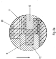
- FIG. 2a an enlarged section is shown in a first orientation in the gravitational field.
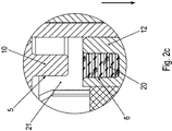
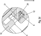
- FIG. 2b an enlarged section is shown in a second orientation in the gravitational field.
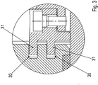
- FIG. 3 the corresponding enlarged section of a second embodiment of the invention is shown.
- FIG. 4 is shown as a further inventive embodiment, an inventive linear drive, in particular spindle drive, in a sectional view.
- FIG. 5 is an in FIG. 1 inserted intermediate ring 12 shown in an oblique view in a first viewing direction.
- the intermediate ring 12 is shown in an oblique view in a different viewing direction.
- the spindle drive on a housing part 1 which is connected on the output side with a housing part 4 and the drive side with a housing part 10, in particular bearing flange, in which a bearing 43 is accommodated, which supports the spindle 2 of the spindle drive.
- the spindle 2 is connected via a coupling with the rotor shaft of an electric motor, not shown.
- the rotor shaft is rotatably mounted in a housing of the electric motor, wherein the housing is screw-connected to the housing part 10th
- the spindle 2 can be set in rotary motion by the electric motor.
- the spindle 2 has an external thread and / or is preferably designed as a ball screw, trapezoidal threaded spindle or planetary roller spindle.
- a spindle nut 11 has an internal thread, which is in engagement with the external thread of the spindle 2.
- the spindle nut 11 is in the housing part 1 linear, ie in the axial direction, ie in the direction parallel to the axial direction of the rotor shaft of the electric motor out.
- the housing part 1 has guide grooves, in which sliding blocks, in particular made of plastic Nuts, are received, wherein the sliding blocks are connected to the spindle nut 11 or a part permanently connected to it.
- a piston rod 3 On the spindle nut 11, a piston rod 3 is fixed, which is supported in the housing part 4 by means of a sliding bearing 42.
- a scraper 41 and an axially disposed between the scraper 41 and the sliding bearing 42 seal 40 is arranged.
- a ring member 7 is screw-connected by means of axially aligned connecting screws 8.
- the screw heads of the connecting screws 8 are arranged on the end face of the connecting screws 8 facing the electric motor.
- the ring member 7 has an annular groove 6, the annular axis is aligned coaxially with the axis of the spindle 2 or the rotor shaft of the electric motor.
- the annular groove is thus open to the side facing away from the electric motor side of the electric motor.
- an intermediate ring 12 is connected to the motor-facing side of the spindle nut 11 with the spindle nut 11.
- the intermediate ring 12 covers the screw heads of the connecting screws 8.
- the intermediate ring 12 axially directed recesses 50, in which protrude the screw heads.
- the rotatably connected to the spindle nut intermediate ring 12 has an open towards the engine annular groove 9.
- annular collar formed on the housing part 10 penetrates into the annular groove 9.
- the intermediate ring 12 is connected by means of at least one radially continuous screw 44, in particular grub screw with the spindle nut 11.
- the recesses 50 are spaced apart in the circumferential direction, in particular spaced regularly from one another.
- the depressions 50 are thus arranged on the spindle nut 11 facing side of the intermediate ring 12.
- the annular groove 9 is arranged on the side facing away from the spindle nut 11 side of the intermediate ring 12.
- annular groove 9 With the spindle nut 11 on its side facing away from the engine axially an annular groove 6 and arranged on its axially facing the engine side, an annular groove 9.
- the annular groove 6 of the intermediate ring 12 is at least with their in the gravitational direction, ie in FIG. 2a indicated arrow direction, lower area completely below the oil level in the interior of the spindle drive.
- the in FIG. 2a immersed area immersed in oil 20.
- the outstanding over the oil level part of the annular groove 6 is filled with air, which is not shown.
- the spindle drive is the axial direction aligned transversely to the direction of gravity.
- the axial direction is aligned perpendicular to the direction of gravity.
- the annular groove 6 is filled with air 21, in particular completely filled with air 21, when the spindle nut retracts from above into the oil bath.
- the collar 5 moves from the oil bath in the filled with air 21 annular groove 21 a.
- the gap between the collar 5 and annular groove 6 is also sealed by oil. By means of the sealing oil in the gap, it is difficult for the compressed oil-air mixture to escape.
- the annular groove 6 is filled with oil 20 when moving out of the annular groove 6 from the oil bath.
- the collar displaced 5 when entering the annular groove 6, the oil 20, which but hardly flows out of the compressed volume through the gap between the collar 5 and groove wall.
- Advantage of this invention is also that after retraction of the respective collar in the respective annular groove of the pressure built up in the annular groove degrades by outflow of the compressed medium through the gap.
- a simple retraction is made possible without overcoming a clipping of the spindle drive. Because without the invention braking the spindle nut 11 moves to the housing part to stop and then builds up a tension between the internal thread of the spindle nut 11 and external thread of the spindle 2, which leads to a self-locking, which must be overcome during the later start.
- a first annular groove 9 is formed on the intermediate ring 12 which is connected to the spindle nut 11, in particular screw-connected, wherein the intermediate ring 12 is screwed by at least one radially through the intermediate ring 12 continuous screw with the spindle nut 11, wherein the screw in a radially directed threaded bore of the spindle nut is screwed.
- a second annular groove 6 is formed on the ring member 7, which is screw-connected to the piston rod 3, for which purpose the ring member 7 has an internal thread and the piston rod 3 has an external thread, wherein axially by a radially projecting on the spindle nut 11 annular collar continuous connecting screws in a respective axially directed threaded bore of the ring member 7 are screwed, the screw heads of the connecting screws on the side facing away from the ring member 7 side of the spindle nut 11 radially projecting annular collar abut, wherein the intermediate ring 12 circumferentially spaced recesses, in each of which Protrudes screw head.
- the piston rod 3 is supported on the housing via a plain bearing.
- the made of plastic nuts are pin-connected to the ring member 7, in particular with hollow clamping pins, and / or screw-connected and guided in a housing arranged on the axially extending longitudinal groove.
- the housing is formed from metallic housing parts 4 and 10 and the intermediate housing part 1.
- annular groove 6 and / or 9 replaced by a concentric annular groove assembly 30.
- the formed on the housing part 4 or 10 annular collar is replaced by a concentric arrangement 31 annular collars.
- the arrangements 31 and 30 of the collars are arranged such that in each case an annular collar of the arrangement 31 in one of the annular grooves of the assembly 30 is retractable.
- the ring member 7 and the spindle nut 11 are made in one piece and / or in one piece.
Landscapes
- Engineering & Computer Science (AREA)
- General Engineering & Computer Science (AREA)
- Mechanical Engineering (AREA)
- Transmission Devices (AREA)
Claims (9)
- Entraînement à broche comprenant un carter, une broche (2), en particulier une broche filetée, une broche à filetage trapézoïdal, une vis à billes ou une vis à rouleaux planétaires, et un écrou (11) en liaison opérante avec ladite broche (2),
ledit écrou (11) de broche étant guidé, sur le carter, de façon telle qu'il puisse être animé d'un mouvement d'avance ou de recul lors d'un mouvement rotatoire de la broche (2) dans la direction axiale de ladite broche,
caractérisé par le fait que
l'écrou (11) de broche est muni d'une rainure annulaire (9), au moins sur un côté axial, ou bien est relié, notamment par vissage, à une pièce pourvue d'une rainure annulaire (9),
un collet annulaire (5) étant façonné sur ledit carter,
sachant que ledit collet (5) pénètre, ou s'engage dans ladite rainure annulaire (9) lorsque ledit écrou (11) de broche atteint un emplacement axial associé, ou correspondant. - Entraînement à broche selon la revendication 1,
caractérisé par le fait que
l'écrou (11) de broche est respectivement muni d'une rainure annulaire (9), de part et d'autre dans le sens axial, ou bien est relié, notamment par vissage, à une pièce respective pourvue d'une rainure annulaire (9) respective. - Entraînement à broche selon la revendication 1 ou 2,
caractérisé par le fait
qu'un espace interstitiel est prévu entre la rainure annulaire (9) et le collet (5) associé, lors d'une pénétration ou d'un engagement du collet (5) considéré dans la rainure annulaire (9) considérée, en particulier lorsque l'écrou (11) de broche atteint un emplacement axial associé, ou correspondant. - Entraînement à broche selon au moins l'une des revendications précédentes,
caractérisé par le fait que
le carter entoure un espace intérieur dans lequel l'écrou (11) de broche est logé, et dans lequel de l'huile (20) est au moins partiellement déversée. - Entraînement à broche selon au moins l'une des revendications précédentes,
caractérisé par le fait
qu'une première rainure annulaire (9) est pratiquée dans une bague intercalaire (12) qui est reliée à l'écrou (11) de broche, notamment par vissage,
et qui, en particulier, est reliée par vissage audit écrou (11) de broche à l'aide d'au moins une vis traversant ladite bague intercalaire (12) dans le sens radial, sachant notamment que ladite vis est vissée dans un perçage taraudé à orientation radiale dudit écrou (11) de broche. - Entraînement à broche selon au moins l'une des revendications précédentes,
caractérisé par le fait
qu'une seconde rainure annulaire (6) est pratiquée dans une pièce annulaire (7) reliée, par vissage, à une tige (3) de piston, sachant notamment que ladite pièce annulaire (7) et ladite tige (3) de piston sont respectivement pourvues, à cette fin, d'un filetage intérieur et d'un filetage extérieur,
sachant que des vis de liaison (8), traversant axialement un collet annulaire (5) faisant radialement saillie au-delà de l'écrou (11) de broche, sont vissées dans un perçage taraudé respectif de ladite pièce annulaire (7), orienté dans le sens axial,
les têtes desdites vis de liaison (8) étant alors notamment en applique contre le côté, pointant à l'opposé de ladite pièce annulaire (7), dudit collet annulaire (5) faisant radialement saillie au-delà de l'écrou (11) de broche,
la bague intercalaire (12) étant dotée de renfoncements (50) distants les uns des autres dans la direction circonférentielle, dans lesquels une tête de vis s'engage à chaque fois. - Entraînement à broche selon au moins l'une des revendications précédentes,
caractérisé par le fait que
la tige (3) de piston est en appui contre le carter par l'intermédiaire d'un palier de glissement (42). - Entraînement à broche selon au moins l'une des revendications précédentes,
caractérisé par le fait que
des coulisseaux, notamment des coulisseaux fabriqués en matière plastique, sont reliés à la pièce annulaire (7) par des goupilles, en particulier par des goupilles de serrage creuses, et/ou sont reliés par vissage et sont guidés dans une rainure située sur le carter. - Entraînement à broche selon au moins l'une des revendications précédentes,
caractérisé par le fait que
le carter est constitué de parties métalliques (1, 4).
Applications Claiming Priority (3)
| Application Number | Priority Date | Filing Date | Title |
|---|---|---|---|
| DE102014018919 | 2014-12-22 | ||
| DE102015000358.5A DE102015000358B3 (de) | 2014-12-22 | 2015-01-20 | Spindelantrieb mit einem Gehäuse, einer Spindel, und einer mit der Spindel in Wirkverbindung stehenden Spindelmutter |
| PCT/EP2015/002310 WO2016102036A1 (fr) | 2014-12-22 | 2015-11-18 | Entraînement à broche muni d'un carter, d'une broche, et d'un écrou de broche coopérant avec la broche |
Publications (2)
| Publication Number | Publication Date |
|---|---|
| EP3237779A1 EP3237779A1 (fr) | 2017-11-01 |
| EP3237779B1 true EP3237779B1 (fr) | 2019-01-09 |
Family
ID=55135075
Family Applications (1)
| Application Number | Title | Priority Date | Filing Date |
|---|---|---|---|
| EP15812949.4A Active EP3237779B1 (fr) | 2014-12-22 | 2015-11-18 | Transmission à vis avec un boîtier, une vis et un écrou en connexion avec la vis |
Country Status (5)
| Country | Link |
|---|---|
| US (1) | US10808812B2 (fr) |
| EP (1) | EP3237779B1 (fr) |
| CN (1) | CN107110313B (fr) |
| DE (1) | DE102015000358B3 (fr) |
| WO (1) | WO2016102036A1 (fr) |
Family Cites Families (10)
| Publication number | Priority date | Publication date | Assignee | Title |
|---|---|---|---|---|
| US2631709A (en) * | 1949-05-02 | 1953-03-17 | Boeing Co | Limit stop mechanism |
| GB881194A (en) * | 1958-01-18 | 1961-11-01 | Garringtons Ltd | Improvements relating to shock absorbers |
| DE202006003130U1 (de) | 2005-02-26 | 2006-07-06 | Linak A/S | Linearantrieb |
| JP2007089275A (ja) | 2005-09-21 | 2007-04-05 | Smc Corp | 電動シリンダ |
| DE202009013875U1 (de) * | 2008-10-29 | 2009-12-17 | Sumitomo (Shi) Demag Plastics Machinery Gmbh | Spindelanordnung zur Relativverstellung eines Maschinenelements zu einer Spindel |
| EP2194295B1 (fr) | 2008-12-08 | 2012-03-28 | Schaeffler Technologies AG & Co. KG | Unité d'entraînement électromotrice |
| US8733192B2 (en) * | 2011-03-11 | 2014-05-27 | Timotion Technology Co., Ltd. | High-load linear actuator |
| TWI516696B (zh) | 2013-05-03 | 2016-01-11 | Timotion Technology Co Ltd | Electric cylinder with cushioning structure |
| CN203926710U (zh) | 2014-07-04 | 2014-11-05 | 第一传动科技股份有限公司 | 线性致动装置及其缓冲机构 |
| DE102014224259A1 (de) * | 2014-11-27 | 2016-06-02 | Robert Bosch Gmbh | Linearaktuator |
-
2015
- 2015-01-20 DE DE102015000358.5A patent/DE102015000358B3/de active Active
- 2015-11-18 WO PCT/EP2015/002310 patent/WO2016102036A1/fr active Application Filing
- 2015-11-18 CN CN201580062267.6A patent/CN107110313B/zh active Active
- 2015-11-18 EP EP15812949.4A patent/EP3237779B1/fr active Active
- 2015-11-18 US US15/538,522 patent/US10808812B2/en active Active
Non-Patent Citations (1)
| Title |
|---|
| None * |
Also Published As
| Publication number | Publication date |
|---|---|
| US20170350478A1 (en) | 2017-12-07 |
| US10808812B2 (en) | 2020-10-20 |
| CN107110313A (zh) | 2017-08-29 |
| CN107110313B (zh) | 2019-11-29 |
| WO2016102036A1 (fr) | 2016-06-30 |
| DE102015000358B3 (de) | 2016-02-11 |
| EP3237779A1 (fr) | 2017-11-01 |
Similar Documents
| Publication | Publication Date | Title |
|---|---|---|
| DE102007043391A1 (de) | Aktuator mit verlagerbarem Ausleger | |
| DE102010021536B4 (de) | Spindelantrieb | |
| EP3189235B1 (fr) | Pompe à cavité progressive | |
| DE102016124117B4 (de) | Türkomponente mit einem steuerbaren Drehdämpfer | |
| WO2010089073A1 (fr) | Moteur de broche | |
| EP2715188A1 (fr) | Arbre pourvu d'un palier | |
| EP3417183B1 (fr) | Articulation à rotule | |
| DE102016124115B4 (de) | Drehdämpfer | |
| DE102013214733A1 (de) | Linearantrieb | |
| EP1170518B1 (fr) | Unité de palier verrouillable | |
| DE102006060681B3 (de) | Dichtung für Gewindetrieb | |
| DE102009007952B4 (de) | Spindelmotor | |
| EP2891824B1 (fr) | Tiroir | |
| DE102013215259B4 (de) | Radialflexibles Wälzlager | |
| EP2707629B1 (fr) | Dispositif d'étanchéification d'une chambre de pompage d'une pompe à piston tournant, et pompe à piston tournant dotée de ce dispositif | |
| DE102015211477B4 (de) | Hydrostatischer Kupplungsaktor | |
| EP3237779B1 (fr) | Transmission à vis avec un boîtier, une vis et un écrou en connexion avec la vis | |
| EP1496600A2 (fr) | Actionneur linéaire | |
| EP3106698A1 (fr) | Engrenage mécanique doté d'un arrêt du couple résistant | |
| DE102012214552A1 (de) | Mutter-Spindel-Vorrichtung und Aktorik für ein Getriebe einer Kurbelwellenriemenscheibe | |
| EP2826946B1 (fr) | Dispositif de blocage de tige pour stores | |
| DE102019214037A1 (de) | Druckbereitstellungseinrichtung | |
| DE102014224499A1 (de) | Elektrozylinder mit Verdrehsicherung über Laufrollen | |
| DE102019104125A1 (de) | Kugelgewindetrieb mit Verdrehsicherung | |
| DE102013102841A1 (de) | Selbstreinigender Spindelantrieb |
Legal Events
| Date | Code | Title | Description |
|---|---|---|---|
| STAA | Information on the status of an ep patent application or granted ep patent |
Free format text: STATUS: THE INTERNATIONAL PUBLICATION HAS BEEN MADE |
|
| PUAI | Public reference made under article 153(3) epc to a published international application that has entered the european phase |
Free format text: ORIGINAL CODE: 0009012 |
|
| STAA | Information on the status of an ep patent application or granted ep patent |
Free format text: STATUS: REQUEST FOR EXAMINATION WAS MADE |
|
| 17P | Request for examination filed |
Effective date: 20170724 |
|
| AK | Designated contracting states |
Kind code of ref document: A1 Designated state(s): AL AT BE BG CH CY CZ DE DK EE ES FI FR GB GR HR HU IE IS IT LI LT LU LV MC MK MT NL NO PL PT RO RS SE SI SK SM TR |
|
| AX | Request for extension of the european patent |
Extension state: BA ME |
|
| DAV | Request for validation of the european patent (deleted) | ||
| DAX | Request for extension of the european patent (deleted) | ||
| REG | Reference to a national code |
Ref country code: DE Ref legal event code: R079 Ref document number: 502015007667 Country of ref document: DE Free format text: PREVIOUS MAIN CLASS: F16H0025200000 Ipc: F16H0057040000 |
|
| RIC1 | Information provided on ipc code assigned before grant |
Ipc: F16H 57/04 20100101AFI20180606BHEP Ipc: F16H 25/20 20060101ALI20180606BHEP |
|
| GRAP | Despatch of communication of intention to grant a patent |
Free format text: ORIGINAL CODE: EPIDOSNIGR1 |
|
| STAA | Information on the status of an ep patent application or granted ep patent |
Free format text: STATUS: GRANT OF PATENT IS INTENDED |
|
| INTG | Intention to grant announced |
Effective date: 20180726 |
|
| GRAS | Grant fee paid |
Free format text: ORIGINAL CODE: EPIDOSNIGR3 |
|
| GRAA | (expected) grant |
Free format text: ORIGINAL CODE: 0009210 |
|
| STAA | Information on the status of an ep patent application or granted ep patent |
Free format text: STATUS: THE PATENT HAS BEEN GRANTED |
|
| AK | Designated contracting states |
Kind code of ref document: B1 Designated state(s): AL AT BE BG CH CY CZ DE DK EE ES FI FR GB GR HR HU IE IS IT LI LT LU LV MC MK MT NL NO PL PT RO RS SE SI SK SM TR |
|
| REG | Reference to a national code |
Ref country code: GB Ref legal event code: FG4D Free format text: NOT ENGLISH |
|
| REG | Reference to a national code |
Ref country code: CH Ref legal event code: EP Ref country code: AT Ref legal event code: REF Ref document number: 1087708 Country of ref document: AT Kind code of ref document: T Effective date: 20190115 |
|
| REG | Reference to a national code |
Ref country code: DE Ref legal event code: R096 Ref document number: 502015007667 Country of ref document: DE |
|
| REG | Reference to a national code |
Ref country code: IE Ref legal event code: FG4D Free format text: LANGUAGE OF EP DOCUMENT: GERMAN |
|
| REG | Reference to a national code |
Ref country code: CH Ref legal event code: NV Representative=s name: HEPP WENGER RYFFEL AG, CH |
|
| REG | Reference to a national code |
Ref country code: NL Ref legal event code: FP |
|
| REG | Reference to a national code |
Ref country code: LT Ref legal event code: MG4D |
|
| PG25 | Lapsed in a contracting state [announced via postgrant information from national office to epo] |
Ref country code: ES Free format text: LAPSE BECAUSE OF FAILURE TO SUBMIT A TRANSLATION OF THE DESCRIPTION OR TO PAY THE FEE WITHIN THE PRESCRIBED TIME-LIMIT Effective date: 20190109 Ref country code: SE Free format text: LAPSE BECAUSE OF FAILURE TO SUBMIT A TRANSLATION OF THE DESCRIPTION OR TO PAY THE FEE WITHIN THE PRESCRIBED TIME-LIMIT Effective date: 20190109 Ref country code: PT Free format text: LAPSE BECAUSE OF FAILURE TO SUBMIT A TRANSLATION OF THE DESCRIPTION OR TO PAY THE FEE WITHIN THE PRESCRIBED TIME-LIMIT Effective date: 20190509 Ref country code: LT Free format text: LAPSE BECAUSE OF FAILURE TO SUBMIT A TRANSLATION OF THE DESCRIPTION OR TO PAY THE FEE WITHIN THE PRESCRIBED TIME-LIMIT Effective date: 20190109 Ref country code: PL Free format text: LAPSE BECAUSE OF FAILURE TO SUBMIT A TRANSLATION OF THE DESCRIPTION OR TO PAY THE FEE WITHIN THE PRESCRIBED TIME-LIMIT Effective date: 20190109 Ref country code: FI Free format text: LAPSE BECAUSE OF FAILURE TO SUBMIT A TRANSLATION OF THE DESCRIPTION OR TO PAY THE FEE WITHIN THE PRESCRIBED TIME-LIMIT Effective date: 20190109 Ref country code: NO Free format text: LAPSE BECAUSE OF FAILURE TO SUBMIT A TRANSLATION OF THE DESCRIPTION OR TO PAY THE FEE WITHIN THE PRESCRIBED TIME-LIMIT Effective date: 20190409 |
|
| PG25 | Lapsed in a contracting state [announced via postgrant information from national office to epo] |
Ref country code: BG Free format text: LAPSE BECAUSE OF FAILURE TO SUBMIT A TRANSLATION OF THE DESCRIPTION OR TO PAY THE FEE WITHIN THE PRESCRIBED TIME-LIMIT Effective date: 20190409 Ref country code: IS Free format text: LAPSE BECAUSE OF FAILURE TO SUBMIT A TRANSLATION OF THE DESCRIPTION OR TO PAY THE FEE WITHIN THE PRESCRIBED TIME-LIMIT Effective date: 20190509 Ref country code: RS Free format text: LAPSE BECAUSE OF FAILURE TO SUBMIT A TRANSLATION OF THE DESCRIPTION OR TO PAY THE FEE WITHIN THE PRESCRIBED TIME-LIMIT Effective date: 20190109 Ref country code: GR Free format text: LAPSE BECAUSE OF FAILURE TO SUBMIT A TRANSLATION OF THE DESCRIPTION OR TO PAY THE FEE WITHIN THE PRESCRIBED TIME-LIMIT Effective date: 20190410 Ref country code: LV Free format text: LAPSE BECAUSE OF FAILURE TO SUBMIT A TRANSLATION OF THE DESCRIPTION OR TO PAY THE FEE WITHIN THE PRESCRIBED TIME-LIMIT Effective date: 20190109 Ref country code: HR Free format text: LAPSE BECAUSE OF FAILURE TO SUBMIT A TRANSLATION OF THE DESCRIPTION OR TO PAY THE FEE WITHIN THE PRESCRIBED TIME-LIMIT Effective date: 20190109 |
|
| REG | Reference to a national code |
Ref country code: DE Ref legal event code: R097 Ref document number: 502015007667 Country of ref document: DE |
|
| PG25 | Lapsed in a contracting state [announced via postgrant information from national office to epo] |
Ref country code: RO Free format text: LAPSE BECAUSE OF FAILURE TO SUBMIT A TRANSLATION OF THE DESCRIPTION OR TO PAY THE FEE WITHIN THE PRESCRIBED TIME-LIMIT Effective date: 20190109 Ref country code: SK Free format text: LAPSE BECAUSE OF FAILURE TO SUBMIT A TRANSLATION OF THE DESCRIPTION OR TO PAY THE FEE WITHIN THE PRESCRIBED TIME-LIMIT Effective date: 20190109 Ref country code: AL Free format text: LAPSE BECAUSE OF FAILURE TO SUBMIT A TRANSLATION OF THE DESCRIPTION OR TO PAY THE FEE WITHIN THE PRESCRIBED TIME-LIMIT Effective date: 20190109 Ref country code: DK Free format text: LAPSE BECAUSE OF FAILURE TO SUBMIT A TRANSLATION OF THE DESCRIPTION OR TO PAY THE FEE WITHIN THE PRESCRIBED TIME-LIMIT Effective date: 20190109 Ref country code: EE Free format text: LAPSE BECAUSE OF FAILURE TO SUBMIT A TRANSLATION OF THE DESCRIPTION OR TO PAY THE FEE WITHIN THE PRESCRIBED TIME-LIMIT Effective date: 20190109 Ref country code: CZ Free format text: LAPSE BECAUSE OF FAILURE TO SUBMIT A TRANSLATION OF THE DESCRIPTION OR TO PAY THE FEE WITHIN THE PRESCRIBED TIME-LIMIT Effective date: 20190109 |
|
| PLBE | No opposition filed within time limit |
Free format text: ORIGINAL CODE: 0009261 |
|
| STAA | Information on the status of an ep patent application or granted ep patent |
Free format text: STATUS: NO OPPOSITION FILED WITHIN TIME LIMIT |
|
| PG25 | Lapsed in a contracting state [announced via postgrant information from national office to epo] |
Ref country code: SM Free format text: LAPSE BECAUSE OF FAILURE TO SUBMIT A TRANSLATION OF THE DESCRIPTION OR TO PAY THE FEE WITHIN THE PRESCRIBED TIME-LIMIT Effective date: 20190109 |
|
| 26N | No opposition filed |
Effective date: 20191010 |
|
| PG25 | Lapsed in a contracting state [announced via postgrant information from national office to epo] |
Ref country code: SI Free format text: LAPSE BECAUSE OF FAILURE TO SUBMIT A TRANSLATION OF THE DESCRIPTION OR TO PAY THE FEE WITHIN THE PRESCRIBED TIME-LIMIT Effective date: 20190109 |
|
| PG25 | Lapsed in a contracting state [announced via postgrant information from national office to epo] |
Ref country code: TR Free format text: LAPSE BECAUSE OF FAILURE TO SUBMIT A TRANSLATION OF THE DESCRIPTION OR TO PAY THE FEE WITHIN THE PRESCRIBED TIME-LIMIT Effective date: 20190109 |
|
| PG25 | Lapsed in a contracting state [announced via postgrant information from national office to epo] |
Ref country code: LU Free format text: LAPSE BECAUSE OF NON-PAYMENT OF DUE FEES Effective date: 20191118 Ref country code: MC Free format text: LAPSE BECAUSE OF FAILURE TO SUBMIT A TRANSLATION OF THE DESCRIPTION OR TO PAY THE FEE WITHIN THE PRESCRIBED TIME-LIMIT Effective date: 20190109 |
|
| REG | Reference to a national code |
Ref country code: BE Ref legal event code: MM Effective date: 20191130 |
|
| PG25 | Lapsed in a contracting state [announced via postgrant information from national office to epo] |
Ref country code: IE Free format text: LAPSE BECAUSE OF NON-PAYMENT OF DUE FEES Effective date: 20191118 |
|
| PG25 | Lapsed in a contracting state [announced via postgrant information from national office to epo] |
Ref country code: BE Free format text: LAPSE BECAUSE OF NON-PAYMENT OF DUE FEES Effective date: 20191130 |
|
| PG25 | Lapsed in a contracting state [announced via postgrant information from national office to epo] |
Ref country code: CY Free format text: LAPSE BECAUSE OF FAILURE TO SUBMIT A TRANSLATION OF THE DESCRIPTION OR TO PAY THE FEE WITHIN THE PRESCRIBED TIME-LIMIT Effective date: 20190109 |
|
| PG25 | Lapsed in a contracting state [announced via postgrant information from national office to epo] |
Ref country code: HU Free format text: LAPSE BECAUSE OF FAILURE TO SUBMIT A TRANSLATION OF THE DESCRIPTION OR TO PAY THE FEE WITHIN THE PRESCRIBED TIME-LIMIT; INVALID AB INITIO Effective date: 20151118 Ref country code: MT Free format text: LAPSE BECAUSE OF FAILURE TO SUBMIT A TRANSLATION OF THE DESCRIPTION OR TO PAY THE FEE WITHIN THE PRESCRIBED TIME-LIMIT Effective date: 20190109 |
|
| PG25 | Lapsed in a contracting state [announced via postgrant information from national office to epo] |
Ref country code: MK Free format text: LAPSE BECAUSE OF FAILURE TO SUBMIT A TRANSLATION OF THE DESCRIPTION OR TO PAY THE FEE WITHIN THE PRESCRIBED TIME-LIMIT Effective date: 20190109 |
|
| PGFP | Annual fee paid to national office [announced via postgrant information from national office to epo] |
Ref country code: NL Payment date: 20231016 Year of fee payment: 9 Ref country code: FR Payment date: 20230929 Year of fee payment: 9 |
|
| PGFP | Annual fee paid to national office [announced via postgrant information from national office to epo] |
Ref country code: GB Payment date: 20231006 Year of fee payment: 9 |
|
| PGFP | Annual fee paid to national office [announced via postgrant information from national office to epo] |
Ref country code: IT Payment date: 20231010 Year of fee payment: 9 Ref country code: DE Payment date: 20231130 Year of fee payment: 9 Ref country code: CH Payment date: 20231214 Year of fee payment: 9 Ref country code: AT Payment date: 20231103 Year of fee payment: 9 |