EP3236235B1 - System und verfahren zur bewertung des blasenbildungspotenzials in einer struktur - Google Patents
System und verfahren zur bewertung des blasenbildungspotenzials in einer struktur Download PDFInfo
- Publication number
- EP3236235B1 EP3236235B1 EP17158610.0A EP17158610A EP3236235B1 EP 3236235 B1 EP3236235 B1 EP 3236235B1 EP 17158610 A EP17158610 A EP 17158610A EP 3236235 B1 EP3236235 B1 EP 3236235B1
- Authority
- EP
- European Patent Office
- Prior art keywords
- test chamber
- environment
- bubble formation
- detector
- environment test
- Prior art date
- Legal status (The legal status is an assumption and is not a legal conclusion. Google has not performed a legal analysis and makes no representation as to the accuracy of the status listed.)
- Active
Links
Images



Classifications
-
- G—PHYSICS
- G01—MEASURING; TESTING
- G01N—INVESTIGATING OR ANALYSING MATERIALS BY DETERMINING THEIR CHEMICAL OR PHYSICAL PROPERTIES
- G01N3/00—Investigating strength properties of solid materials by application of mechanical stress
- G01N3/08—Investigating strength properties of solid materials by application of mechanical stress by applying steady tensile or compressive forces
- G01N3/10—Investigating strength properties of solid materials by application of mechanical stress by applying steady tensile or compressive forces generated by pneumatic or hydraulic pressure
- G01N3/12—Pressure testing
-
- G—PHYSICS
- G01—MEASURING; TESTING
- G01N—INVESTIGATING OR ANALYSING MATERIALS BY DETERMINING THEIR CHEMICAL OR PHYSICAL PROPERTIES
- G01N17/00—Investigating resistance of materials to the weather, to corrosion, or to light
- G01N17/002—Test chambers
-
- G—PHYSICS
- G01—MEASURING; TESTING
- G01N—INVESTIGATING OR ANALYSING MATERIALS BY DETERMINING THEIR CHEMICAL OR PHYSICAL PROPERTIES
- G01N21/00—Investigating or analysing materials by the use of optical means, i.e. using sub-millimetre waves, infrared, visible or ultraviolet light
- G01N21/17—Systems in which incident light is modified in accordance with the properties of the material investigated
Definitions
- the present disclosure relates to testing and evaluating structures, and more particularly to a system and method for evaluation bubble formation potential in a structure.
- bubbles in structures such as laminated structures that may include a decorative layer of material attached to a surface of another layer material is a recurring problem in numerous industries including, for example, construction, aviation, automobile, marine, train, recreation and printing industries.
- bubble formation is often unpredictable and difficult to eliminate.
- the appearance of bubbles in decorative surfaces of such structures may occur only after a considerable length of time, e.g., days or even months and as a result of certain environmental conditions.
- the decorative laminate must be removed and the underlying surface is cleaned. The decorative laminate is then reapplied. This process is typically a time and labor intensive procedure without any assurances the bubbling will not reoccur.
- ALIG I ET AL "Characterization of coating systems by scanning acoustic microscopy: Debonding, blistering and surface topology", PROCESS IN ORGANIC COATINGS, ELSEVIER BV, NL, vol. 64, no. 2-3, 1 February 2009 (2009-02-01), pages 112-119, XP025884306 , discloses the use of scanning acoustic microscopy to monitor coating adhesion and bubble formation.
- US 2015/0355074 A1 states, according to its abstract, a type of testing equipment for detecting the failure process of the thermal barrier coating in a simulated working environment.
- a system for evaluating bubble formation potential in a structure is defined in claim 1.
- a method for evaluating bubble formation potential in a structure is defined in claim 11.
- the detector and illumination source are contained in the environment test chamber.
- the detector is outside the environment test chamber.
- the environment test chamber is a portable environment test chamber.
- the user interface is at remote geographic location from the environment test chamber.
- the system includes a sample holder for holding the structure under test and the sample holder includes a mechanism for positioning the structure under test at different angles relative to the detector.
- the user interface includes a computer system and an algorithm running on the computer system that is configured to evaluate the images from the detector to determine a bubble formation potential of the structure under test based on environmental conditions within the environment test chamber.
- the system may also include at least one of a radiation level sensor for detecting a radiation level within the environment test chamber; a particle level sensor to detect a level of particles within the environment test chamber; a bacteria sensor to detect any bacteria within the environment test chamber; and an illumination sensor to detect an amount of illumination of the structure under test.
- a radiation level sensor for detecting a radiation level within the environment test chamber
- a particle level sensor to detect a level of particles within the environment test chamber
- a bacteria sensor to detect any bacteria within the environment test chamber
- an illumination sensor to detect an amount of illumination of the structure under test.
- the system may also include at least one other environment controller for controlling at least one of a radiation level within the environment test chamber, a particle level within the environment test chamber and bacteria within the environment test chamber.
- the system may include a sample holder for holding a plurality of structures for evaluating bubble formation potential simultaneously and a plurality of detectors for capturing images of at least a front side and a back side of each structure.
- the sample holder may be configured for moving the structures relative to the detectors.
- the system may further include a positioning mechanism associated with the detectors for moving the detectors relative to the structures.
- a portable testing apparatus or system and method for evaluating bubble formation potential in a laminated structure or test sample.
- the system and method is configured to simulate a variety of environmental conditions to induce bubble formation in a surface of the laminated structure or test sample.
- Data is collected about inducing the bubble formation for analysis or evaluation.
- the data collected includes capturing images of the laminated structure or test sample under the variety of environmental conditions.
- the captured images are evaluated to detect bubble formation under the variety of environmental conditions.
- the bubble formation detected is evaluated to determine the bubble formation potential of the laminated structure under test under normal or real-life application or use of the structure.
- FIG. 1 is a block schematic diagram of an example of a system 100 for evaluating bubble formation potential in a structure 102 or test sample in accordance with an example of the present disclosure.
- the system 100 includes an environment test chamber 104. Depending on the size of the environment test chamber 104, more than one structure 102 or test sample may be evaluated at a time.
- the structure 102 or test sample is a laminated structure.
- the laminated structure may include an upper or outer layer of material that is disposed on a lower or underlying layer of another material.
- the upper or outer layer of material is a layer of decorative material.
- the outer layer of material may be attached or adhered to a surface of the underlying layer of other material by an adhesive, bonding agent or other mechanism for fixedly securing the outer layer of material to the underlying layer of material.
- the outer layer of material may be much thinner and pliable compared to the underlying layer of material.
- the underlying layer of material may be a rigid, stronger material to provide structural support.
- the structure 102 or laminated structure may be a panel or other component used in an interior of an aircraft or other vehicle.
- the system 100 also includes one or more environment controllers 105 for controlling a plurality of environmental conditions within the environment test chamber 104.
- the one or more environment controllers 105 include, but are not necessarily limited to, a temperature controller 106 for controlling a temperature within the environment test chamber 104; a humidity controller 108 for controlling humidity within the environment test chamber 104; and a pressure controller 112 for controlling an air pressure or vacuum within the environment test chamber 104.
- the one or more environment controllers 105 may independently control the environmental conditions within the environment test chamber 104.
- the temperature controller 106 includes a heat source 110.
- the temperature controller 106, humidity controller 108 and pressure controller 112 are within the environment test chamber 104 as shown in the example in FIG. 1 .
- the temperature controller 106, humidity controller 108 and pressure controller 112 are outside of the environment test chamber 104 and elements for modifying or adjusting the temperature, humidity and pressure within the environment test chamber 104 reside within the environment test chamber 104 or are associated with the environment test chamber 104.
- a plurality of sensors 114-116 within the environment test chamber 104 detect or sense the environmental conditions within the environment test chamber 104.
- the plurality of sensors 114-116 includes but is not necessarily limited to a temperature sensor, a humidity sensor and a pressure sensor.
- the temperature sensor, humidity sensor and pressure sensor are respectively associated with the temperature controller 106, humidity controller 108 and pressure controller 112 for controlling environmental conditions within the environment test chamber 104.
- the system 100 also includes one or more other types of environment controllers 118.
- the system 100 includes controllers for controlling at least one of a radiation level within the environment test chamber 104, a particle level within the environment test chamber 104, a bacteria level within the environment test chamber 104, and a brightness or illumination level on the structure 102 or structures under test.
- the plurality of sensors 114-116 may also include a radiation level sensor, a particle level sensor, a bacteria sensor or bacterial level sensor, and a light sensor to detect an amount of illumination of the structure 102 or structures 102 under test.
- the system 100 additionally includes one or more detectors 120 or cameras for capturing images of the structure 102 under test and one or more illumination sources 122 or light sources for controlling illumination of the one or more structures 102 under test.
- the one or more detectors 120 are digital single lens reflex (DSLR) cameras with a time elapsing function that can take a picture at preset time intervals, such as for example about every 5 minutes.
- the one or more detectors 120 are video cameras that have a frame speed that permits images to be extracted at a predetermined frequency. The operating parameters of the one or detectors 120 are set to achieve clear close-up images so that bubble formation is accurately captured or captured with sufficient resolution to detect the bubbles.
- the one or more illumination sources 122 include an adjustable wavelength feature that permits emitting light in all visible colors. An optimal wavelength of the illumination source 122 is dependent on a color of a substrate or surface of the structure 102 under test for best visibility in capturing images of the bubble formation.
- the one or more illumination sources 122 are between about 2.54 cm (1 inch) and about 3.05 m (10 feet) from the structure 102 under test.
- the illumination sources 122 are controllable to provide an illumination level and contrast of the structure 102 under test that the detector 120 or detectors can capture images for detecting bubbles with a dimension or diameter as small as about 0.79 mm (1/32 inch) or larger at certain illumination and contrast settings.
- the one or more detectors 120 and illumination sources 122 include devices or detection systems that emit and detect invisible light or light energy in other spectrums including but not necessarily limited to Gamma rays, X-rays, ultraviolet, infrared, microwave or other forms of radiation or illumination. In other examples, laser emission and detection devices or systems are used. Semiconductor strain gauges, such as piezoresistors or the like, may also be utilized to detect bubble formation.
- a sample holder 124 is provided for holding each structure 102 under test.
- a single sample holder holds multiple structures 102 under test.
- the sample holder 124 includes a mechanism for positioning the structure 102 under test at different angles relative to a lens 126 or receiver of the detector 120. The mechanism moves or pivots a surface of the structure 102 under test between an angle of about zero degrees and about 90 degrees relative to the lens 126 or receiver of the detector 120. Examples of sample holders 124 include but are not necessarily limited to clamp-on devices, vacuum devices or electromagnetic devices.
- multiple detectors 120 are used to view the structure 102 or structures 102 under test at different angles between about zero degrees and about 90 degrees relative to a plane of a surface of the structure 102.
- the system 100 further includes a user interface 128 coupled to the environment test chamber 104.
- the user interface 128 may be a remote user interface similar to that described with reference to FIG. 3 .
- the user interface 128 is coupled to the temperature controller 106, the humidity controller 108 and the pressure controller 112 for setting and adjusting environmental conditions within the environment test chamber 104.
- the user interface 128 is also coupled to the one or more illumination sources 122 for setting and adjusting illumination of the structure 102 or structures under test.
- the user interface 128 is configured for controlling the controllers 106, 108, 112 and 118 either together or independently for modifying the environmental conditions within the environment chamber 104.
- the user interface 128 is also configured for controlling the illumination of the structure 102 or structures by the one or more illumination sources 122 together with the controllers or independently.
- the user interface 128 is also coupled to the detector 120 or detectors for receiving the captured images of the structure 102 or structures under test for detecting bubbles.
- the user interface 128 includes a computer system or other electronic device for performing evaluation of the structure 102 or structures under test based on images captured by the detector 120 or detectors.
- the system 100 further includes an algorithm 130 or module running on the computer system.
- the algorithm 130 is configured to determine bubble formation potential of the structure 102 or structures under test based on environmental conditions within the environment test chamber 104.
- the algorithm 130 evaluates the images from the detector 120 or detectors and detects bubble formation from evaluation of the images.
- the algorithm 130 uses a database 132 for evaluating the bubble formation potential of the structure 102.
- the database 132 contains performance relationships of different structures between extreme environmental conditions within the environment test chamber 104 and normal environmental conditions or real-life environmental conditions under which the structures may be exposed during their useful life and/or normal intended use.
- the database 132 contains performance relationships for multiple different structures that may be tested in the environment test chamber 104.
- the extreme environmental conditions used for testing structures 102 within the environment test chamber 104 is intended to accelerate the process of bubble formation or ageing of the structure 102 compared to the environmental conditions the structure 102 would be exposed to under normal or real-life application or use of the structure 102.
- Bubble formation potential in the structure 102 under normal or real-life environmental conditions is determinable from the performance relationships in the database 132 by the algorithm 130 in a much shorter period of time by applying the extreme environmental conditions in the environment test chamber 104 to cause bubble formation.
- FIG. 2 is a block schematic diagram of an example of a system 200 for evaluating bubble formation potential in a structure in accordance with another example of the present disclosure.
- the detector 120 and illumination sources 122 are contained within the environment test chamber 104.
- the detector 120 of the system 200 is outside the environment test chamber 104.
- the illumination sources 122 are also outside the environment test chamber 104 as shown in the example in FIG. 2 .
- the illumination sources 122 are inside the environment test chamber 104 similar to that shown in FIG. 1 and the detector 120 is outside the environment test chamber 104.
- the environment test chamber 104 includes a viewing window 202 through which the detector 120 can capture images of the structure 102 under test while an evaluation for bubble formation potential is being performed.
- FIG. 3 is a block schematic diagram of an example of a system 300 for evaluating bubble formation potential in a structure in accordance with a further example of the present disclosure.
- the user interface 128 is a remote user interface, that is, the remote user interface 128 is at a remote geographic location from the environment test chamber 104.
- the environment test chamber 104 is a portable environment test chamber.
- the portable environment test chamber 104 is transported by an owner of the system 100 to a manufacturer or supplier of the structures 102 for testing and evaluation of different laminated structure constructs.
- the remote user interface 128 is at the owner's location or place of business which is at a different geographic location from the manufacturer's or supplier's place of business.
- the remote user interface 128 is coupled via a network 302 or other communications link to the environment test chamber 104.
- the network 302 may be the Internet, a proprietary network or other type network that may be a secure network.
- the controllers 106, 108, 112 and 118, detector 120 and illumination sources 122 are controlled by the remote user interface 128 via the network 302. Images captured by the detector 120 are transmitted back to the remote user interface 128 via the network 302, either together or independently.
- the system 300 includes a network interface 304 associated with the environment test chamber 104 through which the controllers 106, 108, 112 and 118, detector 120 and illumination sources 122 are coupled to the network 302 and by the network 302 to the remote user interface 128.
- FIG. 4 is a block schematic diagram of an example of an arrangement 400 for evaluating multiple structures 402a-402f or test samples simultaneously in accordance with another example of the present disclosure.
- the arrangement 400 may be used in association with any of the systems 100, 200 or 300 described with reference to FIGS. 1-3 .
- the arrangement 400 includes a single sample holder or a plurality of sample holders 404 configured for holding the multiple structures 402a-402f.
- the arrangement also includes one or more detectors 120a and 120b or cameras. In the example illustrated in FIG. 4 , the arrangement 400 includes at least two detectors 120a and 120b.
- the multiple structures 402a-402f are arranged by the sample holders 404 around at least a first detector 120a for capturing images of a first surface 406a-406f or front side of each structure 402a-402f for evaluating bubble formation potential in the structures 402a-402f.
- the first detector 120a is positioned in a center of the structures 402a-402f which defines a circle or other geometric shape surrounding the first detector 120a.
- At least a second detector 120b is positioned outside the structures 402a-402f or on an opposite side of the structures 402a-402f from the first detector 120a.
- the second detector 120b is positioned for capturing images of a second surface 408a-408f or back side of each structure 402a-402f for evaluating bubble formation potential in the structures 402a-402f.
- the arrangement 400 includes only the first detector 120a or a plurality of detectors 120a with the multiple structures 402a-402f surrounding the detector 120a or detectors 120a, or the arrangement 400 includes only the second detector 120b or a plurality of detectors 120b positioned outside the structures 402a-402f.
- the sample holder or sample holders 404 are configured for movement relative to four-axes for positioning the structures 402a-402f relative to the first detector 120a and the second detector 120b for capturing images of the surfaces of the structures 402a-402f during evaluation of bubble formation potential as described herein.
- the sample holder or sample holders 404 rotate the structures 402a-402f about the first detector 120a and move each structure 402a-402f in X, Y, and Z axes directions relative to a lens 126 or radiation receiver of each detector 120a and 120b.
- the first detector 120a and the second detector 120b may remain stationary or fixed in location.
- the structures 402a-402f are moved simultaneously so that each structure 402a-402f is moved in front of the detectors 120a and 120b for capturing the images of the surfaces of the structures 402a-402f.
- the structures 402a-402b are moved by the sample holder or holders 404 intermittently and the images are captured when the structures 402a-402b are stationary.
- the structures 402a-402b are moved by the sample holder or holders 404 continuously. The detector settings are adjusted to capture clear images of the moving structures 402a-402b.
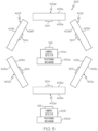
- FIG. 5 is a block schematic diagram of an example of an arrangement 500 for evaluating multiple structures 402a-402f or test samples simultaneously in accordance with a further example of the present disclosure.
- the arrangement 500 may be used in association with any of the systems 100, 200 or 300 described with reference to FIGS. 1-3 .
- the arrangement 500 may be similar to the arrangement 400 in FIG. 4 except a single sample holder or a plurality of sample holders 504 remain stationary or fixed in location and the detectors 120a and/or 120b are moved relative to the structures 402a-402f for capturing images of both surfaces 406a-406f and 408a-408f of each structure 402a-402f during evaluation of bubble formation potential in the structure 402a-402f.
- a positioning mechanism 510a and 510b is associated with each detector 120a and 120b for movement of each detector 120a and 120b.
- Each positioning mechanism 510a and 510b is configured for moving the associated detector 120a or 120b in four-axes of motion for respectively positioning each detector 120a and 120b relative to the structures 402a-402f.
- the positioning mechanism 510a rotates the first detector 120a about an axis out of the page for capturing images of the first surfaces 406a-406f or front side of each structure 402a-402f.
- the positioning mechanism 510a also moves the detector 120a in X, Y and Z axes directions relative to each structure 402a-402f.
- the positioning mechanism 510b moves the second detector 120b circumferentially about the structures 402a-402f to capture images of the second surface 408a-408f or back side of each structure 402a-402f during evaluation of bubble formation potential in the structure 402a-402f.
- the positioning mechanism 510b also moves the second detector 120b in X, Y and Z axes directions relative to each structure 402a-402b for capturing images of the second surface 408a-408f during evaluation of bubble formation potential in the structure 402a-402f.
- the first detector 120a and the second detector 120b may be moved one at a time or simultaneously.
- the first detector 120a and the second detector 120b are moved simultaneously so that images of the first surfaces 406a-406f and the second surfaces 408a-408f are captured at the same time.
- the detectors 120a and 120b may be moved at different speeds and frequencies.
- the detectors 120a and 120b may also be moved intermittently or continuously. The detectors 120a and 120b are still when capturing images or the detector settings are adjusted to capture clear images while the detector 120a or 120b is moving.
- sample holders 504 are moveable as well as the first detector 120a and second detector 120b as described herein for positioning the structure 402a-402f or the detectors 120a and 120b relative to one another for evaluating bubble formation potential of the structures 402a-402f as described herein.
- the sample holders 504 may be similar to the sample holders 404 described with reference to FIG. 4 .
- FIG. 6 is a flow chart of an example of a method 600 for evaluation bubble formation potential in a structure or test sample in accordance with an example of the present disclosure.
- the method 600 may be embodied in and performed by either of the systems 100, 200 and 300 in FIGS. 1 , 2 and 3 , respectively.
- a structure or test sample is placed within an environment test chamber.
- the structure may be held by a sample holder within the environment test chamber.
- a plurality of initial environmental conditions are set within the environment test chamber containing the structure.
- the plurality of environmental conditions that are set within the environment test chamber includes but is not necessarily limited to temperature, humidity, and pressure or vacuum.
- Other environmental conditions that may be set or detected may include type and level of radiation, type and concentration of particles, illumination level or brightness, and type and concentration of bacteria.
- the environmental conditions are recorded in response to the environment test chamber reaching the initial environmental conditions. Images of the structure are captured over a predetermined time interval after the environment test chamber has reached the initial environmental conditions. In another example, images of the structure are also captured while the environment test chamber is reaching the initial environmental conditions or changing to at least one new environmental test condition.
- the structure is preferably illuminated to a predetermined illumination level or brightness that enables a detector to capture images from which a bubble may be detected with a diameter or dimension as small as about 0.79 mm (1/32 inch) or larger. Capturing images of the structure includes capturing images of the structure between an angle of about zero degrees and about 90 degrees relative to a plane of a surface of the structure.
- the method 600 advances to block 614.
- the bubble formation is evaluated. A size and number of the bubbles are measured or determined for evaluating a bubble formation potential of the structure or test sample. The fewer and/or smaller the bubbles corresponds to a lower bubble formation potential under a certain set of environmental test conditions.
- the method 600 ends at termination 616.
- the structure may be changed and the method 600 may begin again in block 602.
- each block in the flowchart or block diagrams may represent a module, segment, or portion of instructions, which comprises one or more executable instructions for implementing the specified logical function(s).
- the functions noted in the block may occur out of the order noted in the figures.
- two blocks shown in succession may, in fact, be executed substantially concurrently, or the blocks may sometimes be executed in the reverse order, depending upon the functionality involved.
Landscapes
- Life Sciences & Earth Sciences (AREA)
- Immunology (AREA)
- General Physics & Mathematics (AREA)
- Pathology (AREA)
- General Health & Medical Sciences (AREA)
- Physics & Mathematics (AREA)
- Health & Medical Sciences (AREA)
- Chemical & Material Sciences (AREA)
- Analytical Chemistry (AREA)
- Biochemistry (AREA)
- Ecology (AREA)
- Environmental Sciences (AREA)
- Biodiversity & Conservation Biology (AREA)
- Environmental & Geological Engineering (AREA)
- Testing Resistance To Weather, Investigating Materials By Mechanical Methods (AREA)
- Testing Of Devices, Machine Parts, Or Other Structures Thereof (AREA)
- Investigating Materials By The Use Of Optical Means Adapted For Particular Applications (AREA)
- Apparatus Associated With Microorganisms And Enzymes (AREA)
- Investigating Or Analysing Materials By Optical Means (AREA)
Claims (15)
- System (100) zum Bewerten eines Blasenbildungspotentials in einer Struktur, das aufweist:eine Umgebungstestkammer (104);eine Umgebungssteuereinrichtung (105) zum Steuern einer Vielzahl von Umgebungsbedingungen innerhalb der Umgebungstestkammer (104);einen Detektor (120) zum Aufnehmen von Bildern einer zu testenden Struktur innerhalb der Umgebungstestkammer (104);eine Beleuchtungsquelle (122) zum Regeln einer Beleuchtung der zu testenden Struktur innerhalb der Umgebungstestkammer (104); undeine Benutzerschnittstelle (128), die an die Umgebungssteuereinrichtung (105) zum Anpassen der Umgebungsbedingungen innerhalb der Umgebungstestkammer (104) gekoppelt ist, und wobei die Benutzerschnittstelle (128) an die Beleuchtungsquelle (122) zum Einstellen und Anpassen einer Beleuchtung der zu testenden Struktur gekoppelt ist und wobei die Benutzerschnittstelle (128) an den Detektor (120) zum Empfangen der aufgenommenen Bilder gekoppelt ist und eingerichtet ist, ein Blasenbildungspotential in der zu testenden Struktur basierend auf den aufgenommenen Bildern zu bewerten, wobei eine Größe und Anzahl von Blasen bestimmt wird, um das Blasenbildungspotential der Struktur zu bewerten, wobei die zu testende Struktur eine laminierte Struktur ist, die eine äußere Schicht aus einem dekorativen Material aufweist, das auf einer unteren Schicht aus einem anderen Material angeordnet ist.
- System (100) nach Anspruch 1, wobei die Beleuchtungsquelle (122) und der Detektor (120) in der Umgebungstestkammer (104) enthalten sind.
- System (100) nach Anspruch 1 oder 2, wobei sich zumindest der Detektor (120) außerhalb der Umgebungstestkammer (104) befindet.
- System (100) nach einem der Ansprüche 1 bis 3, wobei die Umgebungssteuereinrichtung (105) aufweist:eine Temperatursteuereinrichtung (106) zum Steuern einer Temperatur innerhalb der Umgebungstestkammer (104);eine Feuchtigkeitssteuereinrichtung (108) zum Steuern einer Feuchtigkeit innerhalb der Umgebungstestkammer (104); undeine Drucksteuereinrichtung (112) zum Steuern eines Luftdrucks innerhalb der Umgebungstestkammer (104).
- System (100) nach einem der Ansprüche 1 bis 4, das ferner eine Probenhalteeinrichtung (124) zum Halten der zu testenden Struktur aufweist, wobei die Probenhalteeinrichtung (124) einen Mechanismus zum Positionieren der zu testenden Struktur in verschiedenen Winkeln relativ zum Detektor (120) aufweist.
- System (100) nach einem der Ansprüche 1 bis 5, wobei die Benutzerschnittstelle (128) ein Computersystem aufweist, wobei das System ferner einen Algorithmus aufweist, der auf dem Computersystem läuft, wobei der Algorithmus eingerichtet ist, die Bilder von dem Detektor (120) zu bewerten, um ein Blasenbildungspotential für die zu testende Struktur basierend auf den Umgebungsbedingungen innerhalb der Umgebungstestkammer (104) zu bestimmen.
- System (100) nach einem der Ansprüche 1 bis 6, das ferner zumindest eine weitere Umgebungssteuereinrichtung (118) zum Steuern zumindest eines Bestrahlungspegels innerhalb der Umgebungstestkammer (104), eines Partikelpegels innerhalb der Umgebungstestkammer (104) und/oder von Bakterien innerhalb der Umgebungstestkammer (104) aufweist.
- System (100) nach einem der Ansprüche 1 bis 7, wobei die Beleuchtungsquelle (122) regelbar ist, um einen Beleuchtungspegel der zu testenden Struktur vorzusehen, der es dem Detektor (120) ermöglicht, die Bilder zum Erfassen einer Blase innerhalb einer Dimension oder eines Durchmessers von ungefähr 0,79 mm (1/32 Inch) oder größer aufzunehmen.
- System (100) nach einem der Ansprüche 1 bis 4, das ferner aufweist:eine Probenhalteeinrichtung (124) zum Halten einer Vielzahl von Strukturen zum gleichzeitigen Bewerten eines Blasenbildungspotentials; undeine Vielzahl von Detektoren (120a, 120b) zum Aufnehmen von Bildern von zumindest einer Vorderseite und/oder einer Rückseite von jeder Struktur.
- System (100) nach Anspruch 9, das ferner einen Positionierungsmechanismus (510a, 510b) aufweist, der mit den Detektoren (120a, 120b) verknüpft ist, um die Detektoren (120a, 120b) relativ zu den Strukturen zu bewegen.
- Verfahren zum Bewerten eines Blasenbildungspotentials in einer Struktur, das aufweist:Einstellen einer Vielzahl von anfänglichen Umgebungsbedingungen innerhalb der Umgebungstestkammer (104), die die Struktur enthält;Aufnehmen von Bildern der zu testenden Struktur, während sie sich innerhalb der Umgebungstestkammer (104) über einen vorbestimmten Zeitraum befindet;Erfassen einer Blasenbildung in der Struktur; undBewerten der Blasenbildung in Reaktion auf ein Erfassen der Blasenbildung in der Struktur, wobei eine Größe und Anzahl von Blasen zum Bewerten des Blasenbildungspotentials der Struktur bestimmt wird, undwobei die zu testende Struktur eine laminierte Struktur ist, die eine äußere Schicht aus einem dekorativen Material aufweist, das auf einer unteren Schicht aus einem anderen Material angeordnet ist.
- Verfahren nach Anspruch 11, wobei das Einstellen der Vielzahl von anfänglichen Umgebungsbedingungen aufweist:Einstellen einer Temperatur innerhalb der Umgebungstestkammer (104);Einstellen einer Feuchtigkeit innerhalb der Umgebungstestkammer (104); undEinstellen eines Drucks oder Vakuums innerhalb der Umgebungstestkammer (104).
- Verfahren nach Anspruch 11 oder 12, das ferner ein Ändern zumindest einer Umgebungsbedingung innerhalb der Umgebungstestkammer (104) in Reaktion auf ein Nichterfassen einer Blasenbildung bei einer aktuellen Vielzahl von Umgebungsbedingungen, oder ein Durchführen eines zusätzlichen Tests der Struktur mit der zumindest einen Umgebungsbedingung aufweist, die gegenüber der aktuellen Vielzahl von Umgebungsbedingungen verändert ist.
- Verfahren nach einem der Ansprüche 11 bis 13, wobei das Aufnehmen von Bildern der Struktur ein Beleuchten der Struktur aufweist, um einen Beleuchtungspegel der zu testenden Struktur vorzusehen, der es einem Detektor ermöglicht, die Bilder zum Erfassen einer Blase mit einer Dimension oder einem Durchmesser von ungefähr 0,79 mm (1/32 Inch) oder größer zu erfassen.
- Verfahren nach einem der Ansprüche 11 bis 14, wobei das Aufnehmen von Bildern der Struktur ein Aufnehmen von Bildern der Struktur zwischen einem Winkel von ungefähr 0° und ungefähr 90° relativ zu einer Ebene einer Oberfläche der Struktur aufweist.
Applications Claiming Priority (2)
| Application Number | Priority Date | Filing Date | Title |
|---|---|---|---|
| US201662325567P | 2016-04-21 | 2016-04-21 | |
| US15/218,451 US10139325B2 (en) | 2016-04-21 | 2016-07-25 | System and method for evaluating bubble formation potential in a structure |
Publications (2)
| Publication Number | Publication Date |
|---|---|
| EP3236235A1 EP3236235A1 (de) | 2017-10-25 |
| EP3236235B1 true EP3236235B1 (de) | 2024-05-01 |
Family
ID=58387595
Family Applications (1)
| Application Number | Title | Priority Date | Filing Date |
|---|---|---|---|
| EP17158610.0A Active EP3236235B1 (de) | 2016-04-21 | 2017-03-01 | System und verfahren zur bewertung des blasenbildungspotenzials in einer struktur |
Country Status (3)
| Country | Link |
|---|---|
| US (1) | US10139325B2 (de) |
| EP (1) | EP3236235B1 (de) |
| JP (2) | JP6956504B2 (de) |
Families Citing this family (2)
| Publication number | Priority date | Publication date | Assignee | Title |
|---|---|---|---|---|
| US11394955B2 (en) * | 2020-01-17 | 2022-07-19 | Aptiv Technologies Limited | Optics device for testing cameras useful on vehicles |
| US11868108B2 (en) * | 2021-06-29 | 2024-01-09 | Volvo Car Corporation | Artificial weathering of a multi-dimensional object |
Family Cites Families (26)
| Publication number | Priority date | Publication date | Assignee | Title |
|---|---|---|---|---|
| US5034190A (en) * | 1986-01-31 | 1991-07-23 | Westinghouse Electric Corp. | Apparatus for conducting accelerated corrosion testing of nickel alloys |
| JPS63204134A (ja) * | 1987-02-19 | 1988-08-23 | Toyo Eng Works Ltd | 自走車の可塩害テスト環境試験室 |
| JP2659261B2 (ja) * | 1990-05-01 | 1997-09-30 | 日本ペイント株式会社 | 促進耐候性試験装置 |
| JPH04138337A (ja) * | 1990-09-29 | 1992-05-12 | Idemitsu Kosan Co Ltd | 防錆・防食試験装置 |
| US5854433A (en) | 1996-11-08 | 1998-12-29 | Atlas Electric Devices Co. | Variable rotation and irradiation weathering testing machine |
| US6023985A (en) | 1998-03-16 | 2000-02-15 | Hewlett-Packard Company | Controller for an environmental test chamber |
| JP2000258197A (ja) * | 1999-03-08 | 2000-09-22 | Nec Corp | 環境試験装置及びこれの試験パターンの設定方法 |
| US6720562B2 (en) | 2001-04-02 | 2004-04-13 | Atlas Material Testing Technology, L.L.C. | Accelerated weathering apparatus |
| JP2002350325A (ja) * | 2001-05-29 | 2002-12-04 | Nkk Corp | 疲労損傷モニタリングシステムおよびその方法 |
| JP4714646B2 (ja) * | 2006-07-25 | 2011-06-29 | 新日本製鐵株式会社 | メッキ鋼板の端面耐食性評価用試料、端面耐食性評価装置及び端面耐食性評価方法 |
| JP5493428B2 (ja) * | 2009-03-31 | 2014-05-14 | 岩崎電気株式会社 | 耐候性試験装置 |
| JP5724254B2 (ja) * | 2010-09-10 | 2015-05-27 | 凸版印刷株式会社 | ガス透過性評価方法およびガス透過性評価装置 |
| US9176506B2 (en) | 2010-10-18 | 2015-11-03 | Dongguan City Simplewell Technology Co., Ltd. | Low pressure and high-low temperature test box capable of controlling humidity |
| DE102011085267B4 (de) * | 2011-10-27 | 2013-05-23 | Schott Ag | Schnelltest-Verfahren zur Bewertung der Delaminationsneigung von Glas-Packmitteln |
| US8904887B2 (en) | 2011-11-17 | 2014-12-09 | The Aerospace Corporation | Radio frequency transparent thermal window |
| CN202502035U (zh) * | 2012-03-23 | 2012-10-24 | 中国矿业大学 | 高温环境下激光辐照光学薄膜损伤阈值测量装置 |
| CN103091189B (zh) | 2013-01-10 | 2014-09-24 | 湘潭大学 | 一种模拟热障涂层服役环境并实时检测其失效的试验装置 |
| JP2014163780A (ja) * | 2013-02-25 | 2014-09-08 | Yoshiharu Maruyama | 耐環境試験方法 |
| TW201447277A (zh) * | 2013-06-04 | 2014-12-16 | Biotronik Se & Co Kg | 感應單元,電子模組以及計算各電子模組之腐蝕物暴露水準之方法 |
| WO2014209997A1 (en) * | 2013-06-24 | 2014-12-31 | Film Sales Tools, Inc. | Portable gravel impact damage simulator |
| CN203350162U (zh) * | 2013-07-05 | 2013-12-18 | 昆明理工大学 | 酸雨模拟腐蚀装置 |
| JP5865879B2 (ja) * | 2013-09-19 | 2016-02-17 | エスペック株式会社 | 環境試験装置 |
| US10768092B2 (en) * | 2013-09-27 | 2020-09-08 | Luna Innovations Incorporated | Measurement systems and methods for corrosion testing of coatings and materials |
| JP6289269B2 (ja) * | 2014-05-29 | 2018-03-07 | 新日鐵住金ステンレス株式会社 | すきま腐食試験方法 |
| CN204666567U (zh) * | 2015-06-18 | 2015-09-23 | 三峡大学 | 一种隔音隔震环境试验箱 |
| CN104964912B (zh) * | 2015-06-19 | 2017-11-03 | 河海大学 | 一种沥青长期老化和水损害耦合作用室内加速模拟方法 |
-
2016
- 2016-07-25 US US15/218,451 patent/US10139325B2/en active Active
-
2017
- 2017-03-01 EP EP17158610.0A patent/EP3236235B1/de active Active
- 2017-04-04 JP JP2017074105A patent/JP6956504B2/ja active Active
-
2021
- 2021-03-01 JP JP2021032153A patent/JP7149361B2/ja active Active
Non-Patent Citations (1)
| Title |
|---|
| ALIG I ET AL: "Characterization of coating systems by scanning acoustic microscopy: Debonding, blistering and surface topology", PROCESS IN ORGANIC COATINGS, ELSEVIER BV, NL, vol. 64, no. 2-3, 1 February 2009 (2009-02-01), pages 112 - 119, XP025884306, ISSN: 0300-9440, [retrieved on 20081113], DOI: 10.1016/J.PORGCOAT.2008.09.013 * |
Also Published As
| Publication number | Publication date |
|---|---|
| EP3236235A1 (de) | 2017-10-25 |
| US20170307493A1 (en) | 2017-10-26 |
| JP2017223652A (ja) | 2017-12-21 |
| JP6956504B2 (ja) | 2021-11-02 |
| JP2021119342A (ja) | 2021-08-12 |
| US10139325B2 (en) | 2018-11-27 |
| JP7149361B2 (ja) | 2022-10-06 |
Similar Documents
| Publication | Publication Date | Title |
|---|---|---|
| JP2023140336A (ja) | コーティング欠陥のためコーティング表面を検査する方法 | |
| US20140249689A1 (en) | System and method for controlling thermographic measuring process | |
| CN106556608B (zh) | 一种检测产品表面缺陷的方法和系统 | |
| JP6288063B2 (ja) | 動的観察方法および動的観察装置 | |
| US10139325B2 (en) | System and method for evaluating bubble formation potential in a structure | |
| CN108072665A (zh) | 机器视觉检测实验平台 | |
| EP3255417B1 (de) | Hyperspektrales boreskopsystem | |
| CN104061947A (zh) | 一种动态目标模拟系统 | |
| CN111009015B (zh) | 一种标定装置和标定方法 | |
| US20200271682A1 (en) | Systems and Methods for Environmental Factor Interaction Characterization | |
| Borovoy et al. | Pressure sensitive paint application in shock wind tunnel | |
| CN104849281A (zh) | 一种材料表面裂纹数量和位置检测方法 | |
| CN109540477B (zh) | 一种tft测试装置及其测试方法 | |
| WO2018118426A2 (en) | Dynamic blackbody scene display | |
| CN105203559B (zh) | 一种多层石墨烯污点拍照检测装置 | |
| JP2017223652A5 (de) | ||
| CN116136467A (zh) | 制造参考样本的方法、测量液滴的方法和测量液滴的装置 | |
| KR102697656B1 (ko) | 액체에 포함된 이물질 광학검사 장치 및 방법 | |
| KR102246219B1 (ko) | 전자 부품의 적외선 검사 장치 및 그 방법 | |
| Egami et al. | In-flight application of pressure sensitive paint | |
| Nakakita et al. | Unsteady pressure-sensitive paint measurement for oscillating shock wave in supersonic nozzle | |
| US11467435B2 (en) | Device and method for detecting the sparkle effect of a transparent sample arranged in front of an image source | |
| JP2005326827A (ja) | 配向膜の方向性検知方法、及びその装置 | |
| Ibrahim | Molecular Self-Assembly of Carbon Nanosheets via AFM Nanoprinting | |
| JP2005043290A (ja) | シール描画検査装置、および、シール描画検査方法 |
Legal Events
| Date | Code | Title | Description |
|---|---|---|---|
| PUAI | Public reference made under article 153(3) epc to a published international application that has entered the european phase |
Free format text: ORIGINAL CODE: 0009012 |
|
| STAA | Information on the status of an ep patent application or granted ep patent |
Free format text: STATUS: REQUEST FOR EXAMINATION WAS MADE |
|
| 17P | Request for examination filed |
Effective date: 20170301 |
|
| AK | Designated contracting states |
Kind code of ref document: A1 Designated state(s): AL AT BE BG CH CY CZ DE DK EE ES FI FR GB GR HR HU IE IS IT LI LT LU LV MC MK MT NL NO PL PT RO RS SE SI SK SM TR |
|
| AX | Request for extension of the european patent |
Extension state: BA ME |
|
| STAA | Information on the status of an ep patent application or granted ep patent |
Free format text: STATUS: EXAMINATION IS IN PROGRESS |
|
| 17Q | First examination report despatched |
Effective date: 20200122 |
|
| RAP3 | Party data changed (applicant data changed or rights of an application transferred) |
Owner name: THE BOEING COMPANY |
|
| GRAP | Despatch of communication of intention to grant a patent |
Free format text: ORIGINAL CODE: EPIDOSNIGR1 |
|
| STAA | Information on the status of an ep patent application or granted ep patent |
Free format text: STATUS: GRANT OF PATENT IS INTENDED |
|
| INTG | Intention to grant announced |
Effective date: 20231016 |
|
| RIN1 | Information on inventor provided before grant (corrected) |
Inventor name: JONES, STEPHEN P Inventor name: ZHU, SHUYING Inventor name: MENTEL, JEFFREY C. Inventor name: WANG, XIAOXI |
|
| P01 | Opt-out of the competence of the unified patent court (upc) registered |
Effective date: 20231218 |
|
| GRAS | Grant fee paid |
Free format text: ORIGINAL CODE: EPIDOSNIGR3 |
|
| GRAA | (expected) grant |
Free format text: ORIGINAL CODE: 0009210 |
|
| STAA | Information on the status of an ep patent application or granted ep patent |
Free format text: STATUS: THE PATENT HAS BEEN GRANTED |
|
| AK | Designated contracting states |
Kind code of ref document: B1 Designated state(s): AL AT BE BG CH CY CZ DE DK EE ES FI FR GB GR HR HU IE IS IT LI LT LU LV MC MK MT NL NO PL PT RO RS SE SI SK SM TR |
|
| REG | Reference to a national code |
Ref country code: GB Ref legal event code: FG4D |
|
| REG | Reference to a national code |
Ref country code: CH Ref legal event code: EP |
|
| REG | Reference to a national code |
Ref country code: DE Ref legal event code: R096 Ref document number: 602017081463 Country of ref document: DE |
|
| REG | Reference to a national code |
Ref country code: IE Ref legal event code: FG4D |
|
| REG | Reference to a national code |
Ref country code: NL Ref legal event code: FP |
|
| REG | Reference to a national code |
Ref country code: LT Ref legal event code: MG9D |
|
| PG25 | Lapsed in a contracting state [announced via postgrant information from national office to epo] |
Ref country code: IS Free format text: LAPSE BECAUSE OF FAILURE TO SUBMIT A TRANSLATION OF THE DESCRIPTION OR TO PAY THE FEE WITHIN THE PRESCRIBED TIME-LIMIT Effective date: 20240901 |
|
| PG25 | Lapsed in a contracting state [announced via postgrant information from national office to epo] |
Ref country code: BG Free format text: LAPSE BECAUSE OF FAILURE TO SUBMIT A TRANSLATION OF THE DESCRIPTION OR TO PAY THE FEE WITHIN THE PRESCRIBED TIME-LIMIT Effective date: 20240501 |
|
| PG25 | Lapsed in a contracting state [announced via postgrant information from national office to epo] |
Ref country code: FI Free format text: LAPSE BECAUSE OF FAILURE TO SUBMIT A TRANSLATION OF THE DESCRIPTION OR TO PAY THE FEE WITHIN THE PRESCRIBED TIME-LIMIT Effective date: 20240501 Ref country code: HR Free format text: LAPSE BECAUSE OF FAILURE TO SUBMIT A TRANSLATION OF THE DESCRIPTION OR TO PAY THE FEE WITHIN THE PRESCRIBED TIME-LIMIT Effective date: 20240501 |
|
| PG25 | Lapsed in a contracting state [announced via postgrant information from national office to epo] |
Ref country code: GR Free format text: LAPSE BECAUSE OF FAILURE TO SUBMIT A TRANSLATION OF THE DESCRIPTION OR TO PAY THE FEE WITHIN THE PRESCRIBED TIME-LIMIT Effective date: 20240802 |
|
| PG25 | Lapsed in a contracting state [announced via postgrant information from national office to epo] |
Ref country code: PT Free format text: LAPSE BECAUSE OF FAILURE TO SUBMIT A TRANSLATION OF THE DESCRIPTION OR TO PAY THE FEE WITHIN THE PRESCRIBED TIME-LIMIT Effective date: 20240902 |
|
| REG | Reference to a national code |
Ref country code: AT Ref legal event code: MK05 Ref document number: 1682967 Country of ref document: AT Kind code of ref document: T Effective date: 20240501 |
|
| PG25 | Lapsed in a contracting state [announced via postgrant information from national office to epo] |
Ref country code: ES Free format text: LAPSE BECAUSE OF FAILURE TO SUBMIT A TRANSLATION OF THE DESCRIPTION OR TO PAY THE FEE WITHIN THE PRESCRIBED TIME-LIMIT Effective date: 20240501 |
|
| PG25 | Lapsed in a contracting state [announced via postgrant information from national office to epo] |
Ref country code: AT Free format text: LAPSE BECAUSE OF FAILURE TO SUBMIT A TRANSLATION OF THE DESCRIPTION OR TO PAY THE FEE WITHIN THE PRESCRIBED TIME-LIMIT Effective date: 20240501 |
|
| PG25 | Lapsed in a contracting state [announced via postgrant information from national office to epo] |
Ref country code: PL Free format text: LAPSE BECAUSE OF FAILURE TO SUBMIT A TRANSLATION OF THE DESCRIPTION OR TO PAY THE FEE WITHIN THE PRESCRIBED TIME-LIMIT Effective date: 20240501 |
|
| PG25 | Lapsed in a contracting state [announced via postgrant information from national office to epo] |
Ref country code: LV Free format text: LAPSE BECAUSE OF FAILURE TO SUBMIT A TRANSLATION OF THE DESCRIPTION OR TO PAY THE FEE WITHIN THE PRESCRIBED TIME-LIMIT Effective date: 20240501 |
|
| PG25 | Lapsed in a contracting state [announced via postgrant information from national office to epo] |
Ref country code: PT Free format text: LAPSE BECAUSE OF FAILURE TO SUBMIT A TRANSLATION OF THE DESCRIPTION OR TO PAY THE FEE WITHIN THE PRESCRIBED TIME-LIMIT Effective date: 20240902 Ref country code: PL Free format text: LAPSE BECAUSE OF FAILURE TO SUBMIT A TRANSLATION OF THE DESCRIPTION OR TO PAY THE FEE WITHIN THE PRESCRIBED TIME-LIMIT Effective date: 20240501 Ref country code: NO Free format text: LAPSE BECAUSE OF FAILURE TO SUBMIT A TRANSLATION OF THE DESCRIPTION OR TO PAY THE FEE WITHIN THE PRESCRIBED TIME-LIMIT Effective date: 20240801 Ref country code: LV Free format text: LAPSE BECAUSE OF FAILURE TO SUBMIT A TRANSLATION OF THE DESCRIPTION OR TO PAY THE FEE WITHIN THE PRESCRIBED TIME-LIMIT Effective date: 20240501 Ref country code: IS Free format text: LAPSE BECAUSE OF FAILURE TO SUBMIT A TRANSLATION OF THE DESCRIPTION OR TO PAY THE FEE WITHIN THE PRESCRIBED TIME-LIMIT Effective date: 20240901 Ref country code: HR Free format text: LAPSE BECAUSE OF FAILURE TO SUBMIT A TRANSLATION OF THE DESCRIPTION OR TO PAY THE FEE WITHIN THE PRESCRIBED TIME-LIMIT Effective date: 20240501 Ref country code: GR Free format text: LAPSE BECAUSE OF FAILURE TO SUBMIT A TRANSLATION OF THE DESCRIPTION OR TO PAY THE FEE WITHIN THE PRESCRIBED TIME-LIMIT Effective date: 20240802 Ref country code: FI Free format text: LAPSE BECAUSE OF FAILURE TO SUBMIT A TRANSLATION OF THE DESCRIPTION OR TO PAY THE FEE WITHIN THE PRESCRIBED TIME-LIMIT Effective date: 20240501 Ref country code: ES Free format text: LAPSE BECAUSE OF FAILURE TO SUBMIT A TRANSLATION OF THE DESCRIPTION OR TO PAY THE FEE WITHIN THE PRESCRIBED TIME-LIMIT Effective date: 20240501 Ref country code: BG Free format text: LAPSE BECAUSE OF FAILURE TO SUBMIT A TRANSLATION OF THE DESCRIPTION OR TO PAY THE FEE WITHIN THE PRESCRIBED TIME-LIMIT Effective date: 20240501 Ref country code: AT Free format text: LAPSE BECAUSE OF FAILURE TO SUBMIT A TRANSLATION OF THE DESCRIPTION OR TO PAY THE FEE WITHIN THE PRESCRIBED TIME-LIMIT Effective date: 20240501 Ref country code: RS Free format text: LAPSE BECAUSE OF FAILURE TO SUBMIT A TRANSLATION OF THE DESCRIPTION OR TO PAY THE FEE WITHIN THE PRESCRIBED TIME-LIMIT Effective date: 20240801 |
|
| PG25 | Lapsed in a contracting state [announced via postgrant information from national office to epo] |
Ref country code: DK Free format text: LAPSE BECAUSE OF FAILURE TO SUBMIT A TRANSLATION OF THE DESCRIPTION OR TO PAY THE FEE WITHIN THE PRESCRIBED TIME-LIMIT Effective date: 20240501 |
|
| PG25 | Lapsed in a contracting state [announced via postgrant information from national office to epo] |
Ref country code: EE Free format text: LAPSE BECAUSE OF FAILURE TO SUBMIT A TRANSLATION OF THE DESCRIPTION OR TO PAY THE FEE WITHIN THE PRESCRIBED TIME-LIMIT Effective date: 20240501 |
|
| PG25 | Lapsed in a contracting state [announced via postgrant information from national office to epo] |
Ref country code: CZ Free format text: LAPSE BECAUSE OF FAILURE TO SUBMIT A TRANSLATION OF THE DESCRIPTION OR TO PAY THE FEE WITHIN THE PRESCRIBED TIME-LIMIT Effective date: 20240501 |
|
| PG25 | Lapsed in a contracting state [announced via postgrant information from national office to epo] |
Ref country code: SK Free format text: LAPSE BECAUSE OF FAILURE TO SUBMIT A TRANSLATION OF THE DESCRIPTION OR TO PAY THE FEE WITHIN THE PRESCRIBED TIME-LIMIT Effective date: 20240501 Ref country code: RO Free format text: LAPSE BECAUSE OF FAILURE TO SUBMIT A TRANSLATION OF THE DESCRIPTION OR TO PAY THE FEE WITHIN THE PRESCRIBED TIME-LIMIT Effective date: 20240501 |
|
| PG25 | Lapsed in a contracting state [announced via postgrant information from national office to epo] |
Ref country code: SM Free format text: LAPSE BECAUSE OF FAILURE TO SUBMIT A TRANSLATION OF THE DESCRIPTION OR TO PAY THE FEE WITHIN THE PRESCRIBED TIME-LIMIT Effective date: 20240501 |
|
| PG25 | Lapsed in a contracting state [announced via postgrant information from national office to epo] |
Ref country code: SM Free format text: LAPSE BECAUSE OF FAILURE TO SUBMIT A TRANSLATION OF THE DESCRIPTION OR TO PAY THE FEE WITHIN THE PRESCRIBED TIME-LIMIT Effective date: 20240501 Ref country code: SK Free format text: LAPSE BECAUSE OF FAILURE TO SUBMIT A TRANSLATION OF THE DESCRIPTION OR TO PAY THE FEE WITHIN THE PRESCRIBED TIME-LIMIT Effective date: 20240501 Ref country code: RO Free format text: LAPSE BECAUSE OF FAILURE TO SUBMIT A TRANSLATION OF THE DESCRIPTION OR TO PAY THE FEE WITHIN THE PRESCRIBED TIME-LIMIT Effective date: 20240501 Ref country code: EE Free format text: LAPSE BECAUSE OF FAILURE TO SUBMIT A TRANSLATION OF THE DESCRIPTION OR TO PAY THE FEE WITHIN THE PRESCRIBED TIME-LIMIT Effective date: 20240501 Ref country code: DK Free format text: LAPSE BECAUSE OF FAILURE TO SUBMIT A TRANSLATION OF THE DESCRIPTION OR TO PAY THE FEE WITHIN THE PRESCRIBED TIME-LIMIT Effective date: 20240501 Ref country code: CZ Free format text: LAPSE BECAUSE OF FAILURE TO SUBMIT A TRANSLATION OF THE DESCRIPTION OR TO PAY THE FEE WITHIN THE PRESCRIBED TIME-LIMIT Effective date: 20240501 |
|
| REG | Reference to a national code |
Ref country code: DE Ref legal event code: R097 Ref document number: 602017081463 Country of ref document: DE |
|
| PG25 | Lapsed in a contracting state [announced via postgrant information from national office to epo] |
Ref country code: IT Free format text: LAPSE BECAUSE OF FAILURE TO SUBMIT A TRANSLATION OF THE DESCRIPTION OR TO PAY THE FEE WITHIN THE PRESCRIBED TIME-LIMIT Effective date: 20240501 |
|
| PLBE | No opposition filed within time limit |
Free format text: ORIGINAL CODE: 0009261 |
|
| STAA | Information on the status of an ep patent application or granted ep patent |
Free format text: STATUS: NO OPPOSITION FILED WITHIN TIME LIMIT |
|
| 26N | No opposition filed |
Effective date: 20250204 |
|
| PG25 | Lapsed in a contracting state [announced via postgrant information from national office to epo] |
Ref country code: SI Free format text: LAPSE BECAUSE OF FAILURE TO SUBMIT A TRANSLATION OF THE DESCRIPTION OR TO PAY THE FEE WITHIN THE PRESCRIBED TIME-LIMIT Effective date: 20240501 |
|
| PG25 | Lapsed in a contracting state [announced via postgrant information from national office to epo] |
Ref country code: SE Free format text: LAPSE BECAUSE OF FAILURE TO SUBMIT A TRANSLATION OF THE DESCRIPTION OR TO PAY THE FEE WITHIN THE PRESCRIBED TIME-LIMIT Effective date: 20240501 |
|
| PG25 | Lapsed in a contracting state [announced via postgrant information from national office to epo] |
Ref country code: MC Free format text: LAPSE BECAUSE OF FAILURE TO SUBMIT A TRANSLATION OF THE DESCRIPTION OR TO PAY THE FEE WITHIN THE PRESCRIBED TIME-LIMIT Effective date: 20240501 |
|
| REG | Reference to a national code |
Ref country code: CH Ref legal event code: H13 Free format text: ST27 STATUS EVENT CODE: U-0-0-H10-H13 (AS PROVIDED BY THE NATIONAL OFFICE) Effective date: 20251024 |
|
| PG25 | Lapsed in a contracting state [announced via postgrant information from national office to epo] |
Ref country code: LU Free format text: LAPSE BECAUSE OF NON-PAYMENT OF DUE FEES Effective date: 20250301 |
|
| REG | Reference to a national code |
Ref country code: BE Ref legal event code: MM Effective date: 20250331 |
|
| PG25 | Lapsed in a contracting state [announced via postgrant information from national office to epo] |
Ref country code: BE Free format text: LAPSE BECAUSE OF NON-PAYMENT OF DUE FEES Effective date: 20250331 |
|
| PG25 | Lapsed in a contracting state [announced via postgrant information from national office to epo] |
Ref country code: CH Free format text: LAPSE BECAUSE OF NON-PAYMENT OF DUE FEES Effective date: 20250331 |
|
| PG25 | Lapsed in a contracting state [announced via postgrant information from national office to epo] |
Ref country code: IE Free format text: LAPSE BECAUSE OF NON-PAYMENT OF DUE FEES Effective date: 20250301 |
|
| PGFP | Annual fee paid to national office [announced via postgrant information from national office to epo] |
Ref country code: GB Payment date: 20260327 Year of fee payment: 10 |
|
| PGFP | Annual fee paid to national office [announced via postgrant information from national office to epo] |
Ref country code: DE Payment date: 20260327 Year of fee payment: 10 |
|
| PGFP | Annual fee paid to national office [announced via postgrant information from national office to epo] |
Ref country code: NL Payment date: 20260326 Year of fee payment: 10 |
|
| PGFP | Annual fee paid to national office [announced via postgrant information from national office to epo] |
Ref country code: FR Payment date: 20260325 Year of fee payment: 10 |