EP3235388B2 - Vorrichtung zum auftragen einer leimspur auf einen umhüllungsstreifen eines stabförmigen produktes der tabak verarbeitenden industrie - Google Patents
Vorrichtung zum auftragen einer leimspur auf einen umhüllungsstreifen eines stabförmigen produktes der tabak verarbeitenden industrie Download PDFInfo
- Publication number
- EP3235388B2 EP3235388B2 EP17166539.1A EP17166539A EP3235388B2 EP 3235388 B2 EP3235388 B2 EP 3235388B2 EP 17166539 A EP17166539 A EP 17166539A EP 3235388 B2 EP3235388 B2 EP 3235388B2
- Authority
- EP
- European Patent Office
- Prior art keywords
- roller
- glue
- stripping
- stripping member
- nozzle
- Prior art date
- Legal status (The legal status is an assumption and is not a legal conclusion. Google has not performed a legal analysis and makes no representation as to the accuracy of the status listed.)
- Active
Links
Images



Classifications
-
- B—PERFORMING OPERATIONS; TRANSPORTING
- B05—SPRAYING OR ATOMISING IN GENERAL; APPLYING FLUENT MATERIALS TO SURFACES, IN GENERAL
- B05C—APPARATUS FOR APPLYING FLUENT MATERIALS TO SURFACES, IN GENERAL
- B05C1/00—Apparatus in which liquid or other fluent material is applied to the surface of the work by contact with a member carrying the liquid or other fluent material, e.g. a porous member loaded with a liquid to be applied as a coating
- B05C1/04—Apparatus in which liquid or other fluent material is applied to the surface of the work by contact with a member carrying the liquid or other fluent material, e.g. a porous member loaded with a liquid to be applied as a coating for applying liquid or other fluent material to work of indefinite length
- B05C1/08—Apparatus in which liquid or other fluent material is applied to the surface of the work by contact with a member carrying the liquid or other fluent material, e.g. a porous member loaded with a liquid to be applied as a coating for applying liquid or other fluent material to work of indefinite length using a roller or other rotating member which contacts the work along a generating line
- B05C1/0813—Apparatus in which liquid or other fluent material is applied to the surface of the work by contact with a member carrying the liquid or other fluent material, e.g. a porous member loaded with a liquid to be applied as a coating for applying liquid or other fluent material to work of indefinite length using a roller or other rotating member which contacts the work along a generating line characterised by means for supplying liquid or other fluent material to the roller
-
- A—HUMAN NECESSITIES
- A24—TOBACCO; CIGARS; CIGARETTES; SIMULATED SMOKING DEVICES; SMOKERS' REQUISITES
- A24C—MACHINES FOR MAKING CIGARS OR CIGARETTES
- A24C5/00—Making cigarettes; Making tipping materials for, or attaching filters or mouthpieces to, cigars or cigarettes
- A24C5/14—Machines of the continuous-rod type
- A24C5/24—Pasting the seam
-
- B—PERFORMING OPERATIONS; TRANSPORTING
- B05—SPRAYING OR ATOMISING IN GENERAL; APPLYING FLUENT MATERIALS TO SURFACES, IN GENERAL
- B05C—APPARATUS FOR APPLYING FLUENT MATERIALS TO SURFACES, IN GENERAL
- B05C1/00—Apparatus in which liquid or other fluent material is applied to the surface of the work by contact with a member carrying the liquid or other fluent material, e.g. a porous member loaded with a liquid to be applied as a coating
- B05C1/04—Apparatus in which liquid or other fluent material is applied to the surface of the work by contact with a member carrying the liquid or other fluent material, e.g. a porous member loaded with a liquid to be applied as a coating for applying liquid or other fluent material to work of indefinite length
- B05C1/08—Apparatus in which liquid or other fluent material is applied to the surface of the work by contact with a member carrying the liquid or other fluent material, e.g. a porous member loaded with a liquid to be applied as a coating for applying liquid or other fluent material to work of indefinite length using a roller or other rotating member which contacts the work along a generating line
- B05C1/0817—Apparatus in which liquid or other fluent material is applied to the surface of the work by contact with a member carrying the liquid or other fluent material, e.g. a porous member loaded with a liquid to be applied as a coating for applying liquid or other fluent material to work of indefinite length using a roller or other rotating member which contacts the work along a generating line characterised by means for removing partially liquid or other fluent material from the roller, e.g. scrapers
-
- B—PERFORMING OPERATIONS; TRANSPORTING
- B05—SPRAYING OR ATOMISING IN GENERAL; APPLYING FLUENT MATERIALS TO SURFACES, IN GENERAL
- B05C—APPARATUS FOR APPLYING FLUENT MATERIALS TO SURFACES, IN GENERAL
- B05C1/00—Apparatus in which liquid or other fluent material is applied to the surface of the work by contact with a member carrying the liquid or other fluent material, e.g. a porous member loaded with a liquid to be applied as a coating
- B05C1/04—Apparatus in which liquid or other fluent material is applied to the surface of the work by contact with a member carrying the liquid or other fluent material, e.g. a porous member loaded with a liquid to be applied as a coating for applying liquid or other fluent material to work of indefinite length
- B05C1/16—Apparatus in which liquid or other fluent material is applied to the surface of the work by contact with a member carrying the liquid or other fluent material, e.g. a porous member loaded with a liquid to be applied as a coating for applying liquid or other fluent material to work of indefinite length only at particular parts of the work
- B05C1/165—Apparatus in which liquid or other fluent material is applied to the surface of the work by contact with a member carrying the liquid or other fluent material, e.g. a porous member loaded with a liquid to be applied as a coating for applying liquid or other fluent material to work of indefinite length only at particular parts of the work using a roller or other rotating member which contacts the work along a generating line
Definitions
- the invention relates to a device for applying a line of glue to a wrapping strip of a rod-shaped product of the tobacco processing industry with the features of the preamble of claim 1.
- the wrapping strip is generally used to fix the shape of the rod-shaped products, which can be, for example, preliminary products such as filter rods or tobacco, or also finished products such as cigarettes, cigarillos, with and without filters.
- the wrapping strip is first diverted and placed on an endless conveyor belt in a continuous production process.
- a filter material made of loose filter material fibers, filter segments or a strand of tobacco fibers that have not yet been fixed is then placed on the wrapping strip.
- the wrapping strip is then guided with the strand lying on top through a shaping section in which the wrapping strip is folded up at the side of the strand and a thin line of glue is applied to one edge.
- the wrapping strip is then folded further around the strand until the edges of the wrapping strip overlap.
- the edges of the wrapping strip are then glued together by applying a small pressure force and/or thermal energy via the glue seam, so that the strand is then fixed in shape in cross-section by the wrapping strip.
- the glue line can also be applied in the form of glue dots at a certain distance apart, which is the case, for example, when the filter segments adhere when glue is applied underneath.
- the glue dots and the tow material are applied in the middle of the wrapping strip at a point well before the wrapping strip is folded over, and serve to pre-fix the filter segments to the wrapping strip.
- the use of glue dots is a special case; the use of a glue line is normal for both monofilters (tow) and multifilters (segments).
- a nozzle with a round opening cross-section with a diameter of e.g. 1.6 mm is provided, through which the glue is continuously applied, e.g. with a gear pump, in a volume specified by the latter.
- the volume of glue applied can be controlled, for example, by controlling the speed of the gear pump.
- a strand speed of more than 600 m/min such as 700 m/min or more, have already been realized, and it cannot be ruled out that the strand speed will be increased even further in order to reduce manufacturing costs.
- a disadvantage of the solution described above is that the glue emerges from the nozzle unevenly across the cross-section due to friction on the inner wall of the nozzle. As a result of this and due to the predominant laminar flow, the glue exit speed is significantly higher in the middle of the nozzle opening than in the edge section of the nozzle opening and has a parabolic shape across the cross-section. Since a certain minimum amount of glue must be applied across the entire width of the glue track to create a glue track of a certain width, and the glue exit speed in the middle of the nozzle opening is inevitably higher than in the edge zone due to the problem described above, the glue is applied in an excessive amount in the middle of the nozzle opening compared to the amount of glue actually required per area.
- the time in which the wrapping strip is guided past the edge sections of the nozzle opening that are parallel to the transport direction is significantly shorter than the time in which the wrapping strip is guided past the middle section of the outlet opening. Both circumstances result in significantly more glue being applied in the middle of the glue line than in the edge sections. In principle, however, it is desirable to apply the glue as evenly as possible for a glue line with a high adhesive strength, whereby a specified minimum amount of glue should not be undercut.
- glue penetration Due to the increased speed of the glue discharge and thus also the amount of glue in the middle of the nozzle's outlet opening, a larger proportion of the glue passes through the porous wrapping strip in the middle of the outlet opening without contributing to the bonding of the edges of the wrapping strip. This effect is also known as glue penetration.
- the glue penetration depends on the porosity of the wrapping strip and increases with it. In addition to an undesirable possible change in the taste of the products, glue penetration leads to undesirable contamination of the entire device or system and the subsequent products. Glue penetration further reduces the adhesive strength in addition to the reduction in the adhesive strength due to the different distribution.
- the filter material Since the filter material is also strongly compressed during strand production and is only stabilised in shape by the drying of the applied acetate, the filter material still exerts a relatively high restoring force at the time of bonding. For this reason, the wrapping strips a hot glue seam with a high, immediately effective adhesive strength is applied.
- the bonding of the edges can optionally be stabilized by a second cold glue seam, also known as a support seam, running parallel to the hot glue seam.
- a second cold glue seam also known as a support seam, running parallel to the hot glue seam.
- the wrapping strip In cigarette machines, the wrapping strip is guided past a heating bar with as little pressure as possible to harden the cold glue seam, while in filter machines, only the hot glue seam is usually hardened by a cooling bar during the production process.
- the optional cold glue seam provided in the filter machine hardens without the addition of thermal energy. In principle, the excess glue can have a detrimental effect on both the hardening process and the guidance of the wrapping strip itself.
- the cold glue line and the hot glue line are applied parallel to a very narrow edge section of the filter's wrapping strip. Due to the very narrow edge strip, the glue lines must be applied with as little deviation in shape as possible from a given course and a given width.
- EP 1 002 468 A2 It is known to apply the glue in the form of a foam, which is formed by adding gas bubbles, in particular inert gas or air bubbles, to the liquid glue.
- the invention is based on the object of providing a generic device with which it is possible to apply a line of glue to a wrapping strip with a very high degree of accuracy, the greatest possible adhesive strength and, at the same time, the least possible contamination of the wrapping strip and the device or the environment.
- a stripping part directed towards the roller is provided between the nozzle and the wrapping strip in the direction of rotation of the roller, which stripping part has a defined distance from the roller.
- the advantage of the proposed solution is that the glue applied by the nozzle to the roller is formed by the stripping part arranged at the defined distance into a glue track with a defined thickness, which corresponds to the defined distance of the stripping part from the roller. It is important for the function of the stripping part that the stripping part is arranged in the direction of rotation between the nozzle and the wrapping strip, so that the glue is first applied by the nozzle to the roller and then the desired glue track is formed from the amount of glue applied by the stripping part during the further rotation of the roller.
- the sole function of the stripping part is to shape the glue track on the roller, so that the glue track can be produced on the roller with a very high degree of shape accuracy and in particular a very high degree of thickness accuracy by appropriately shaping the stripping part and in particular its stripping edge and appropriately positioning the stripping part to the roller and finally applied to the wrapping strip. It is particularly advantageous that the stripping part can be positioned and aligned independently of the nozzle and the application location of the glue line on the wrapping strip, so that the shape of the glue line also occurs independently of the application of the glue to the roller and independently of the application of the glue line to the wrapping strip.
- the stripping part being independent of the nozzle and the independent shaping of the glue line that this enables.
- the shape of the glue line can occur as close as possible to the application of the glue line on the wrapping strip, regardless of the position of the nozzle, thanks to the separate stripping part.
- a further advantage of the invention is that if the stripping part is worn and the glue line no longer corresponds to the required quality, it is possible to replace the stripping part as an individual part. If a glue line with a different geometry is to be applied, this can also be achieved very easily by simply exchanging the stripping part for a stripping part with a different geometry.
- the distance between the stripping part and the roller be variable. This allows the thickness of the glue line to be applied to be varied and, in particular, changed or even regulated according to a predetermined thickness without having to remove the stripping part. must.
- the stripping part can be driven in an oscillating manner by means of a drive device parallel to the rotation axis of the roller.
- the proposed further development makes it possible to remove foreign particles.
- the glue mass can be stimulated to make a homogenizing transverse movement.
- the stripping part and/or the rollers have at least one depression and/or elevation in the surface that comes into contact with the glue.
- the depressions and/or elevations can be used to create a glue track with different thicknesses in the transverse direction or in the longitudinal direction, so that the glue track deliberately has zones or sections that harden quickly or more slowly.
- the depressions and/or elevations are provided in the roller, they can be interrupted in the circumferential direction, so that the glue track is designed with a thickness that changes rhythmically in the direction of travel.
- the depression and/or elevation are provided in the form of closed rings provided on the roller, a glue track with a thickness that changes transversely to the direction of travel can be created.
- Such a glue track can also be created by a stripping part with depressions and/or elevations in the stripping edge.
- the quality of the glue track can be further improved by providing several stripping parts distributed over the circumference of the roller.
- the stripping parts can each have an identical orientation and an identical distance from the roller, so that the glue track is formed on one of the stripping parts in a first step and is then reshaped on the other stripping parts during the further rotational movement of the roller.
- the stripping parts can also have different distances from the roller, particularly in the arrangement in the direction of rotation of the roller, which decrease in each case, so that the glue track is successively formed during the rotational movement of the roller.
- the stripping part is shaped on the surface facing the roller in such a way that a gap with a constant gap width in the direction of rotation of the roller is formed between the surface of the roller and the surface of the stripping part facing the roller.
- the gap with the constant gap width not only strips off the excess glue, but also actively shapes the glue track in the gap over a longer section of the circumference of the roller.
- the stripping part has a width parallel to the axis of rotation of the roller which is larger or at most 1.0 mm narrower than the width of the glue track to be applied to the wrapping strip.
- the stripping part has a distance of 0.01 to 0.1 mm from the roller for a high-quality glue track.
- a glue reservoir can be provided on the roller, into which the glue exiting the nozzle enters and which is limited on one side by the stripping part.
- the glue reservoir serves as a kind of intermediate storage for the glue that is on the roller and from which the roller transports the glue away through its rotating movement.
- the stripping part limits the glue reservoir on one side, so that it practically blocks the glue on the roller and only allows the glue to be transported away through the gap between the stripping part and the roller.
- the stripping part is aligned such that the edge side of the stripping part arranged downstream in the direction of rotation of the roller encloses an angle of at least 20 degrees to the surface of the roller.
- the stripping part is adjustable about a rotation axis, and that the stripping part is aligned such that the rotation axis is aligned parallel to the rotation axis of the roller, and the stripping part is formed by a polygonal profile in a cutting plane perpendicular to its rotation axis.
- the roller preferably has a diameter of 2 to 15 mm and is driven at a speed of 1000 rpm to 12000 rpm.
- the glue preferably has a viscosity of at least 180 mPas and is applied in an amount of 5 g to 40 g per 500 m length of the wrapping strip, the transport speed of the wrapping strip preferably being between 100 m/min and 700 m/min.
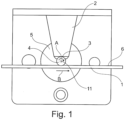
- FIG. 1 is the basic structure of a device with a nozzle 2 fixed to the machine with an outlet opening 3 and a roller 4 arranged at the outlet opening 3 and driven in rotation about an axis of rotation 11 in the direction of arrow A.
- the roller 4 in this case is the end of a shaft leading out of an electric motor 5 and is driven in rotation in the direction of arrow A.
- the electric motor 5 is fixed to the machine in the same way as the nozzle 2 and can therefore be regarded as stationary together with the roller 4 (the leading out shaft).
- an endless wrapping strip 1 can be seen which is transported by means of a transport device (not shown) in the direction of arrow B at a transport speed of 100 m/min to 700 m/min, preferably 600 m/min.
- the roller 4 is arranged between the wrapping strip 1 and the outlet opening 3 of the nozzle 2, i.e. opposite the circumferential section of the roller 4 in which the roller 4 comes to rest on the wrapping strip 1.
- the term "fixed” also includes a roller 4 or a nozzle 2 which can make slight movements with the axis of rotation towards the wrapping strip 1 or towards each other during or before the glue is applied, whereby the alignment of the roller 4 and the nozzle 2 towards each other and towards the wrapping strip 1 can be slightly varied or adjusted.
- the only important thing when interpreting the term "fixed” is that the application movement of the glue line onto the wrapping strip 1 occurs when the wrapping strip 1 moves past the roller 4 or opposite the nozzle 2.
- the glue line is practically transported away from the roller 4 by the movement of the wrapping strip 1, wherein the possible slight movements of the roller 4 or the nozzle 2 for adjusting the alignment and/or during the application of the glue line are to be considered negligible for the application movement of the glue line.
- the roller 4 is driven clockwise in the direction of arrow A, so that the roller 4 moves against the transport direction of the wrapping strip 1 in the section which is opposite the wrapping strip 1 or in the section in which it comes into contact with the wrapping strip 1.
- the glue emerging from the outlet opening 3 of the nozzle 2 is thereby transported away from the roller 4 in a clockwise direction and applied to the wrapping strip 1 in the form of a glue track 6 with a constant width.
- the glue is applied in an amount of 5 g to 40 g per 500 meters of length of the wrapping strip 1 for a linear glue track 6 and up to an amount of 100 g per 500 meters for a flat glue track 6.
- the roller 4 is cleaned again in the movement of the wrapping strip 1, which can also be seen because the layer thickness of the glue on the roller 4 is considerably thinner in this section. This makes it possible to avoid the so-called "glue nose" on the nozzle 2 that previously occurred.
- the width and thickness of the glue line 6 are applied to the wrapping strip 1 much more evenly than was possible with the previously used solution of directly applying the glue line 6 via the nozzle 2, so that after the layers of the wrapping strip 1 have been glued together, a much stronger glue seam with a greater adhesive strength is obtained.
- the greater adhesive strength is achieved by using the glue completely to form a composite layer between the fibers of the wrapping strip 1 for the bonding. This creates a composite layer that is as homogeneous as possible of fibers from the layers of the wrapping strip 1 that are glued together, with glue particles embedded in between.
- This homogeneous composite layer leads to an increased adhesive strength, since a layer consisting exclusively of glue with a lower adhesive strength, as experience has shown, is no longer present. In this case, the use of less glue leads to a higher adhesive strength and less contamination of the machine.
- the glue seam is made of cold glue with a layer consisting exclusively of glue, which is then passed past a heating bar and hardened, there is also the risk that the water in the glue mass will evaporate on the heating bar in the glue mass as it hardens, thereby forming small cavities. These cavities then form interruptions in the glue seam and reduce the adhesive strength by the glue seam tearing open under load in a tear line running through the cavities. Since the glue seam is applied in a much more controlled manner using the solution according to the invention and a layer consisting exclusively of glue in the glue seam can therefore be avoided, the adhesive strength can ultimately be increased using the solution according to the invention.
- the device can produce a very uniform glue seam with a substantially constant thickness and a consistently high adhesive strength even at very high strand speeds. This is because the glue seam is first rubbed to a larger width with a more constant thickness by being applied to the roller 4 before being applied to the wrapping strip 1, and only then is it applied to the wrapping strip 1 by the roller 4.
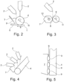
- the roller 4 can be seen with a stripping part 7 directed towards the roller 4 and two possible orientations of a nozzle 2.
- the stripping part 7 is arranged in the direction of the rotation of the roller 4 after the nozzle 2 and before the wrapping strip 1, so that a point on the surface of the roller 4 first passes the fixed nozzle 2, then the stripping part 7 and finally the wrapping strip 1.
- the nozzle 2 is either aligned so that the escaping glue hits the roller 4 directly from above or enters the space between the roller 4 and the stripping part 7.
- the stripping part 7 is arranged with the stripping edge 8, which can only be seen in the following figures, at a predetermined distance from the surface of the roller 4.
- the glue is then transported away by the rotational movement of the roller 4 and accumulated on the stripping part 7 to form a glue reservoir 9. Due to the predetermined distance of the stripping edge 8 from the roller 4, part of the glue can be transported away through the gap between the stripping edge 8 and the surface of the roller 4.
- This glue track 6 with the defined thickness is then applied as glue track 6 to the wrapping strip 1.
- the stripping part 7 serves, through the arrangement and shape of the stripping edge 8, for the active shaping of the glue track 6 formed on the roller 4 and also for the formation of the glue reservoir 9 as an intermediate storage of the glue on the roller 4.
- the stripping part 7 is formed by a plate that is inclined to the roller 4 and is held to the higher-level device by means of a suitable holding device.
- the stripping part 7 is designed as a part independent of the nozzle 2 and as such can be arranged and aligned individually to form the glue track 6.
- the nozzle 2 can in turn be arranged and aligned independently of the stripping part 7 in accordance with the structural boundary conditions for applying the glue to the roller 4.
- the glue application and the shaping of the glue track 6 practically take place at mutually independent points on the circumference of the roller 4, and the nozzle 2 and the stripping part 7 can be shaped, arranged and aligned independently of one another.
- the stripping part 7 is adjustable about a rotation axis 12.
- the stripping part 7 is designed as a polygonal profile, in this case as a hexagonal profile, in a cutting plane perpendicular to its rotation axis 12 and is arranged with a stripping edge 8 at a distance from the roller 4.
- the stripping part 7, like the roller 4, has a constant external shape in the direction of its rotation axes 11 and 12. Furthermore, the stripping part 7 is aligned such that the rotation axis 12 of the stripping part 7 is aligned parallel to the rotation axis 11 of the roller 4.
- a roller 4 with a stripping part 7 and three nozzles 2 or three glue reservoirs 9 produced thereby can be seen.
- glue tracks 6 with a wider geometry or several glue tracks 6 can be produced.
- one glue track 6 can be applied to several different wrapping strips 1 with one roller 4.
- the stripping part 7 is directed with the stripping edge 8 towards the surface 18 of the roller and is arranged such that a gap S is present between the stripping edge 8 and the surface 18 of the roller 4.
- the stripping part 7 has a thickness of at least 0.01 mm and is aligned such that the angle W between the surface 17 of the stripping part 7 facing away from the glue reservoir 9 and the surface 18 of the roller 4 is at least 20 degrees.
- the stripping part 7 can also be adjusted by a suitable drive device to realize different angles W and distances from the roller 4.
- the stripping edge 8 of the stripping part 7 is deburred on the side facing away from the glue reservoir 9 to a dimension D of a maximum of 0.1 mm, so that the stripping edge 8 has a sharpness on this side, which ensures that the glue track 6 formed in the gap S between the stripping edge 8 and the surface 18 of the roller 4 does not widen again after leaving the gap S.
- stripping parts 7 with different geometries and orientations to the roller 4 can be seen, which can be used individually or in combination to form the glue track 6.
- the stripping edge 8 can also be the front edge of a stripping surface 19 of a stripping part 7 facing the roller 4.
- the stripping surface 19 of the stripping part 7 is then preferably formed as a negative surface to the surface 18 of the roller 4, so that between the stripping surface 19 of the stripping part 7 and the surface of the roller 4 a gap S with a constant gap width in the direction of rotation of the roller 4 is formed, in which the glue track 6 is formed.
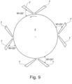
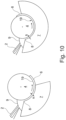
- a roller 4 with several stripping parts 7 in different positions and orientations can be seen, which can be provided individually or in combination for applying the glue and for forming the glue track 6 on the roller 4.
- the stripping part 7 is shaped as a kind of shell part, which has a stripping surface 19 adjoining the stripping edge 8 in the direction of rotation of the roller 4 with a partially circular shape in the manner of a half-shell.
- the radius of the stripping surface 19 is slightly larger than the radius of the roller 4.
- the stripping surface 19 is shaped so that it is concentric with the roller 4, so that a shaping channel with a gap width S that is constant in the direction of rotation of the roller 4 is formed between the stripping surface 19 of the stripping part 7 and the roller 4.
- the stripping part 7 extends, as can be seen in the right-hand illustration, over a circumferential section of up to 180 degrees of the roller 4.
- the stripping part 7 is formed by a collecting tray in which the glue collects.
- the collecting tray has a stripping edge 8 directed towards the roller 4, which is arranged on an edge side 20 of the collecting tray extending in the direction of the roller 4.
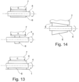
- the embodiment with the stripping part 7 designed as a hexagonal profile is shown again enlarged.
- the stripping part 7 is aligned such that one of the edges forms a stripping edge 8 and is arranged at a defined distance from the roller 4.
- the width C of the stripping part 7 corresponds to the width of the glue track 6, while in the middle illustration the width C is larger and in the lower illustration it is smaller than the width of the glue track 6.
- the stripping part 7 should have a width C which is larger or a maximum of 1.0 mm narrower than the width of the glue track 6 to be applied.
- the width of the glue track 6 to be applied is predetermined and can be adjusted by measuring the amount of glue applied by the nozzle 2 per unit of time, by the gap width S between the stripping edge 8 and the surface 18 of the roller 4 and the speed of the roller 4. If the width C of the stripping part 7 is smaller than the width of the glue track 6 on the roller 4, the glue is formed into a concave surface on the roller 4 and finally rubbed into a wider glue track 6 on the wrapping strip 1.
- the stripping part 7 has a stripping edge 8 which tapers obliquely in the direction of the axis of rotation 11 of the roller 4, so that a conical glue track 6 with a thickness decreasing in the direction of its width is formed on the roller 4.
- a stripping part 7 with a radial recess 13 arranged on the edge can be seen.
- the recess 13 forms a step-shaped glue track 6 which has a first section 21 with a smaller thickness and a second section 22 with a larger thickness.
- the first section 21 with the smaller thickness can be, for example, a base area also referred to as an inner glue section, used for bonding, while the second section 22 with the larger thickness forms the seam section facing the edge of the wrapping strip 1 with a greater adhesive strength.
- FIG 16 A further embodiment can be seen in which the stripping part 7 is provided with two centrally arranged depressions 13, so that the glue track 6 has two sections 23 with a greater thickness and three sections 24 with a smaller thickness.
- the sections 24 are quick-drying due to the smaller thickness, while the sections 23 with the greater thickness are slow-drying.
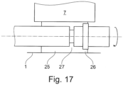
- FIG 17 an embodiment with a stripping part 7 with a straight stripping edge 8 and a roller 4 can be seen, in which a recess 13 and an additional elevation 14 are provided in the roller 4.
- the recess 13 is designed here as a circumferential groove and the elevation 14 as a circumferential shoulder. This makes it possible to form a glue track 6 with a base section 25 with a constant thickness and a first section 26 that is thinner than the base section 25 and a thicker second section 27.
- glue tracks 6 with sections of different thickness can be realized by means of the depressions 13 and the elevations 14, wherein in the event that the depressions 13 and the elevations 14 in the roller 4 are not formed circumferentially, glue tracks 6 with thicker and thinner sections rhythmically interrupted in the longitudinal direction can also be realized.
Landscapes
- Coating Apparatus (AREA)
- Making Paper Articles (AREA)
Priority Applications (1)
| Application Number | Priority Date | Filing Date | Title |
|---|---|---|---|
| PL17166539.1T PL3235388T5 (pl) | 2016-04-20 | 2017-04-13 | Urządzenie do nanoszenia ścieżki kleju na owijkę sztabkowego produktu przemysłu tytoniowego |
Applications Claiming Priority (1)
| Application Number | Priority Date | Filing Date | Title |
|---|---|---|---|
| DE102016107290.7A DE102016107290A1 (de) | 2016-04-20 | 2016-04-20 | Vorrichtung zum Auftragen einer Leimspur auf einen Umhüllungsstreifen eines stabförmigen Produktes der Tabak verarbeitenden Industrie |
Publications (3)
| Publication Number | Publication Date |
|---|---|
| EP3235388A1 EP3235388A1 (de) | 2017-10-25 |
| EP3235388B1 EP3235388B1 (de) | 2019-02-06 |
| EP3235388B2 true EP3235388B2 (de) | 2024-09-25 |
Family
ID=58547424
Family Applications (1)
| Application Number | Title | Priority Date | Filing Date |
|---|---|---|---|
| EP17166539.1A Active EP3235388B2 (de) | 2016-04-20 | 2017-04-13 | Vorrichtung zum auftragen einer leimspur auf einen umhüllungsstreifen eines stabförmigen produktes der tabak verarbeitenden industrie |
Country Status (4)
| Country | Link |
|---|---|
| EP (1) | EP3235388B2 (pl) |
| CN (1) | CN107303011A (pl) |
| DE (1) | DE102016107290A1 (pl) |
| PL (1) | PL3235388T5 (pl) |
Families Citing this family (5)
| Publication number | Priority date | Publication date | Assignee | Title |
|---|---|---|---|---|
| US20210053087A1 (en) * | 2018-02-08 | 2021-02-25 | Philip Morris Products S.A. | Adhesive application roller |
| CN110026317A (zh) * | 2019-05-09 | 2019-07-19 | 东莞市翔奕机械制造有限公司 | 一种浆液涂布装置 |
| CN110815945B (zh) * | 2019-12-04 | 2024-05-10 | 昆山金红凯包装制品有限公司 | 一种输胶抹胶机构 |
| DE102020102744A1 (de) | 2020-02-04 | 2021-08-05 | Hauni Maschinenbau Gmbh | Herstellmaschine zur Herstellung von stabförmigen Produkten aus einem endlosen Strang eines zu einem Rohr verklebten Streifens |
| DE102023110217A1 (de) * | 2023-04-21 | 2024-10-24 | Homag Gmbh | Vorrichtung zum selektiven Auftragen von Haftmitteln, Verfahren zum Beschichten von Werkstücken, beschichtetes Werkstück und Verwendung davon |
Citations (6)
| Publication number | Priority date | Publication date | Assignee | Title |
|---|---|---|---|---|
| US2929352A (en) † | 1957-06-27 | 1960-03-22 | American Mach & Foundry | Casein paster gate improvements |
| DE1241742B (de) † | 1962-07-31 | 1967-06-01 | Hauni Werke Koerber & Co Kg | Strangzigarettenmaschine od. dgl. |
| US3447508A (en) † | 1967-07-13 | 1969-06-03 | Specialty Equipment Corp | Carton blank gluing apparatus |
| US4009657A (en) † | 1975-02-25 | 1977-03-01 | Scott Paper Company | Apparatus for applying fluid to an intaglio roll for transfer to a soft, absorbent fibrous web |
| DE4036726A1 (de) † | 1990-11-17 | 1992-05-21 | Hauni Werke Koerber & Co Kg | Beschichtungsvorrichtung |
| DE102013111625A1 (de) † | 2013-10-22 | 2015-04-23 | Khs Gmbh | Leimschaber, Beleimungseinrichtung mit dem Leimschaber sowie Etikettieraggregat mit der Beleimungseinrichtung |
Family Cites Families (6)
| Publication number | Priority date | Publication date | Assignee | Title |
|---|---|---|---|---|
| DE3713278A1 (de) * | 1986-04-30 | 1987-11-05 | Will E C H Gmbh & Co | Verfahren und vorrichtung zum auftragen einer fliessfaehigen masse auf eine bahn |
| DE4309951A1 (de) * | 1993-03-26 | 1994-09-29 | Hauni Werke Koerber & Co Kg | Leimauftragvorrichtung |
| DE19853833A1 (de) | 1998-11-21 | 2000-05-25 | Hauni Maschinenbau Ag | Verfahren und Anordnung zum Beleimen eines Umhüllungsstreifens für einen Füller der tabakverarbeitenden Industrie |
| DE102009007590A1 (de) * | 2009-02-05 | 2010-09-09 | Hauni Maschinenbau Ag | Beleimung von Materialstreifen der Tabak verarbeitenden Industrie |
| CN103892440B (zh) * | 2014-03-07 | 2015-03-18 | 广东省金叶科技开发有限公司 | 一种干法造纸法生产再造烟叶的设备 |
| DE102014213858B3 (de) | 2014-07-16 | 2015-11-12 | Hauni Maschinenbau Ag | Vorrichtung zum Auftragen einer Leimspur auf einen Umhüllungsstreifen eines stabförmigen Produktes der Tabak verarbeitenden Industrie |
-
2016
- 2016-04-20 DE DE102016107290.7A patent/DE102016107290A1/de not_active Ceased
-
2017
- 2017-04-13 PL PL17166539.1T patent/PL3235388T5/pl unknown
- 2017-04-13 EP EP17166539.1A patent/EP3235388B2/de active Active
- 2017-04-19 CN CN201710256555.6A patent/CN107303011A/zh active Pending
Patent Citations (6)
| Publication number | Priority date | Publication date | Assignee | Title |
|---|---|---|---|---|
| US2929352A (en) † | 1957-06-27 | 1960-03-22 | American Mach & Foundry | Casein paster gate improvements |
| DE1241742B (de) † | 1962-07-31 | 1967-06-01 | Hauni Werke Koerber & Co Kg | Strangzigarettenmaschine od. dgl. |
| US3447508A (en) † | 1967-07-13 | 1969-06-03 | Specialty Equipment Corp | Carton blank gluing apparatus |
| US4009657A (en) † | 1975-02-25 | 1977-03-01 | Scott Paper Company | Apparatus for applying fluid to an intaglio roll for transfer to a soft, absorbent fibrous web |
| DE4036726A1 (de) † | 1990-11-17 | 1992-05-21 | Hauni Werke Koerber & Co Kg | Beschichtungsvorrichtung |
| DE102013111625A1 (de) † | 2013-10-22 | 2015-04-23 | Khs Gmbh | Leimschaber, Beleimungseinrichtung mit dem Leimschaber sowie Etikettieraggregat mit der Beleimungseinrichtung |
Also Published As
| Publication number | Publication date |
|---|---|
| PL3235388T5 (pl) | 2024-12-23 |
| DE102016107290A1 (de) | 2017-10-26 |
| EP3235388B1 (de) | 2019-02-06 |
| PL3235388T3 (pl) | 2019-07-31 |
| CN107303011A (zh) | 2017-10-31 |
| EP3235388A1 (de) | 2017-10-25 |
Similar Documents
| Publication | Publication Date | Title |
|---|---|---|
| DE102014213858B3 (de) | Vorrichtung zum Auftragen einer Leimspur auf einen Umhüllungsstreifen eines stabförmigen Produktes der Tabak verarbeitenden Industrie | |
| EP3235388B1 (de) | Vorrichtung zum auftragen einer leimspur auf einen umhüllungsstreifen eines stabförmigen produktes der tabak verarbeitenden industrie | |
| DE102006058823A1 (de) | Verfahren zum Abtrennen einer Vielzahl von Scheiben von einem Werkstück | |
| EP3822019B1 (de) | Vorrichtung und verfahren zum aufbringen einer materialschicht auf einen oberflächenbereich eines werkstücks | |
| EP2505269A2 (de) | Vorrichtung zum Beleimen eines bewegten Umhüllungsstreifens für stabförmige Produkte der Tabak verarbeitenden Industrie und Anlage mit einer derartigen Vorrichtung | |
| EP4100243B1 (de) | Herstellmaschine zur herstellung von stabförmigen produkten aus einem endlosen strang eines zu einem rohr verklebten streifens | |
| DE102008000763B4 (de) | Teig-Querstrecksystem | |
| EP2644283A1 (de) | Auftragwerk | |
| EP2510791A2 (de) | Vorrichtung zur Formung eines Teigbandes aus zugeführten Teigportionen | |
| EP2550875B1 (de) | Vorrichtung zum Verteilen von Tabak, wie Tabakfasern, Tabakblätter oder Teilen von Tabakblättern | |
| AT507711A1 (de) | Vorrichtung zum formen von gutbällchen, insbesondere aus einer fleischmasse | |
| EP2401928A2 (de) | Einrichtung zur Herstellung von stabförmigen Produkten der Tabak verarbeitenden Industrie | |
| EP3129158B1 (de) | Verfahren und vorrichtung zum beschichten eines sich in bandlaufrichtung bewegenden metallbands sowie anlage zum herstellen von länglichen metallischen walzgütern | |
| EP3056097B1 (de) | Vorrichtung zur herstellung von produkten der tabak verarbeitenden industrie | |
| EP3820310B1 (de) | Vorrichtung und verfahren zum abtrennen von stabförmigen segmenten der tabak verarbeitenden industrie von einem strang | |
| DE102022116185A1 (de) | Maschine und Verfahren der Tabak verarbeitenden Industrie zum Herstellen eines Strangs oder Papierfilters sowie Verwendung der Maschine | |
| DE3825613C2 (de) | Zweistrang-Zigaretten-Fertigungsmaschine | |
| EP1754418B1 (de) | Verfahren und Einrichtung zur Zufuhr eines Zusatzstoffes auf eine Filtermaterialbahn | |
| DE3239467C2 (de) | Vorrichtung zum gleichmäßigen, pulsationsfreien Speisen eines Walzenspaltes | |
| EP0440322A2 (de) | Verfahren und Vorrichtung zum Herstellen eines keramischen Schaumkörpers | |
| WO1988006085A1 (fr) | Laminoir de melange et de cisaillement pour materiaux plastifiables | |
| EP1817159B1 (de) | Verfahren und vorrichtung zum klebstoffauftrag auf wellpappe | |
| DE3144870A1 (de) | "vorrichtung fuer die kontinuierliche verarbeitung von hochproteinhaltigen nahrungmitteln, insbesondere kaesebruch" | |
| EP2801266A2 (de) | Vorrichtung zum Auftragen einer Leimspur auf einen Umhüllungsstreifen eines stabförmigen Produkts der Tabak verarbeitenden Industrie | |
| DE4134676C1 (en) | Simple extruder-calender combination - includes injection head on extruder which enables material to be extruded with a cylindrical cross=section |
Legal Events
| Date | Code | Title | Description |
|---|---|---|---|
| PUAI | Public reference made under article 153(3) epc to a published international application that has entered the european phase |
Free format text: ORIGINAL CODE: 0009012 |
|
| STAA | Information on the status of an ep patent application or granted ep patent |
Free format text: STATUS: THE APPLICATION HAS BEEN PUBLISHED |
|
| AK | Designated contracting states |
Kind code of ref document: A1 Designated state(s): AL AT BE BG CH CY CZ DE DK EE ES FI FR GB GR HR HU IE IS IT LI LT LU LV MC MK MT NL NO PL PT RO RS SE SI SK SM TR |
|
| AX | Request for extension of the european patent |
Extension state: BA ME |
|
| RIN1 | Information on inventor provided before grant (corrected) |
Inventor name: SCHMICK, CLEMENS Inventor name: JANZ, DIETMAR Inventor name: LEICHSENRING, NADINE Inventor name: SCHAFFORZ, MATHIAS Inventor name: HUESER, REIKO Inventor name: SOLTOW, RALF |
|
| STAA | Information on the status of an ep patent application or granted ep patent |
Free format text: STATUS: REQUEST FOR EXAMINATION WAS MADE |
|
| 17P | Request for examination filed |
Effective date: 20180411 |
|
| RBV | Designated contracting states (corrected) |
Designated state(s): AL AT BE BG CH CY CZ DE DK EE ES FI FR GB GR HR HU IE IS IT LI LT LU LV MC MK MT NL NO PL PT RO RS SE SI SK SM TR |
|
| GRAP | Despatch of communication of intention to grant a patent |
Free format text: ORIGINAL CODE: EPIDOSNIGR1 |
|
| STAA | Information on the status of an ep patent application or granted ep patent |
Free format text: STATUS: GRANT OF PATENT IS INTENDED |
|
| RIC1 | Information provided on ipc code assigned before grant |
Ipc: A24C 5/24 20060101AFI20180626BHEP Ipc: B05C 1/08 20060101ALI20180626BHEP Ipc: A24C 5/47 20060101ALI20180626BHEP Ipc: B05C 1/16 20060101ALI20180626BHEP |
|
| INTG | Intention to grant announced |
Effective date: 20180731 |
|
| GRAS | Grant fee paid |
Free format text: ORIGINAL CODE: EPIDOSNIGR3 |
|
| GRAJ | Information related to disapproval of communication of intention to grant by the applicant or resumption of examination proceedings by the epo deleted |
Free format text: ORIGINAL CODE: EPIDOSDIGR1 |
|
| GRAL | Information related to payment of fee for publishing/printing deleted |
Free format text: ORIGINAL CODE: EPIDOSDIGR3 |
|
| STAA | Information on the status of an ep patent application or granted ep patent |
Free format text: STATUS: REQUEST FOR EXAMINATION WAS MADE |
|
| GRAR | Information related to intention to grant a patent recorded |
Free format text: ORIGINAL CODE: EPIDOSNIGR71 |
|
| STAA | Information on the status of an ep patent application or granted ep patent |
Free format text: STATUS: GRANT OF PATENT IS INTENDED |
|
| INTC | Intention to grant announced (deleted) | ||
| GRAA | (expected) grant |
Free format text: ORIGINAL CODE: 0009210 |
|
| STAA | Information on the status of an ep patent application or granted ep patent |
Free format text: STATUS: THE PATENT HAS BEEN GRANTED |
|
| INTG | Intention to grant announced |
Effective date: 20181220 |
|
| AK | Designated contracting states |
Kind code of ref document: B1 Designated state(s): AL AT BE BG CH CY CZ DE DK EE ES FI FR GB GR HR HU IE IS IT LI LT LU LV MC MK MT NL NO PL PT RO RS SE SI SK SM TR |
|
| REG | Reference to a national code |
Ref country code: GB Ref legal event code: FG4D Free format text: NOT ENGLISH |
|
| REG | Reference to a national code |
Ref country code: CH Ref legal event code: EP Ref country code: AT Ref legal event code: REF Ref document number: 1094292 Country of ref document: AT Kind code of ref document: T Effective date: 20190215 |
|
| REG | Reference to a national code |
Ref country code: DE Ref legal event code: R096 Ref document number: 502017000730 Country of ref document: DE |
|
| REG | Reference to a national code |
Ref country code: IE Ref legal event code: FG4D Free format text: LANGUAGE OF EP DOCUMENT: GERMAN |
|
| REG | Reference to a national code |
Ref country code: NL Ref legal event code: FP |
|
| REG | Reference to a national code |
Ref country code: LT Ref legal event code: MG4D |
|
| PG25 | Lapsed in a contracting state [announced via postgrant information from national office to epo] |
Ref country code: FI Free format text: LAPSE BECAUSE OF FAILURE TO SUBMIT A TRANSLATION OF THE DESCRIPTION OR TO PAY THE FEE WITHIN THE PRESCRIBED TIME-LIMIT Effective date: 20190206 Ref country code: LT Free format text: LAPSE BECAUSE OF FAILURE TO SUBMIT A TRANSLATION OF THE DESCRIPTION OR TO PAY THE FEE WITHIN THE PRESCRIBED TIME-LIMIT Effective date: 20190206 Ref country code: NO Free format text: LAPSE BECAUSE OF FAILURE TO SUBMIT A TRANSLATION OF THE DESCRIPTION OR TO PAY THE FEE WITHIN THE PRESCRIBED TIME-LIMIT Effective date: 20190506 Ref country code: SE Free format text: LAPSE BECAUSE OF FAILURE TO SUBMIT A TRANSLATION OF THE DESCRIPTION OR TO PAY THE FEE WITHIN THE PRESCRIBED TIME-LIMIT Effective date: 20190206 Ref country code: PT Free format text: LAPSE BECAUSE OF FAILURE TO SUBMIT A TRANSLATION OF THE DESCRIPTION OR TO PAY THE FEE WITHIN THE PRESCRIBED TIME-LIMIT Effective date: 20190606 |
|
| PG25 | Lapsed in a contracting state [announced via postgrant information from national office to epo] |
Ref country code: GR Free format text: LAPSE BECAUSE OF FAILURE TO SUBMIT A TRANSLATION OF THE DESCRIPTION OR TO PAY THE FEE WITHIN THE PRESCRIBED TIME-LIMIT Effective date: 20190507 Ref country code: BG Free format text: LAPSE BECAUSE OF FAILURE TO SUBMIT A TRANSLATION OF THE DESCRIPTION OR TO PAY THE FEE WITHIN THE PRESCRIBED TIME-LIMIT Effective date: 20190506 Ref country code: RS Free format text: LAPSE BECAUSE OF FAILURE TO SUBMIT A TRANSLATION OF THE DESCRIPTION OR TO PAY THE FEE WITHIN THE PRESCRIBED TIME-LIMIT Effective date: 20190206 Ref country code: HR Free format text: LAPSE BECAUSE OF FAILURE TO SUBMIT A TRANSLATION OF THE DESCRIPTION OR TO PAY THE FEE WITHIN THE PRESCRIBED TIME-LIMIT Effective date: 20190206 Ref country code: LV Free format text: LAPSE BECAUSE OF FAILURE TO SUBMIT A TRANSLATION OF THE DESCRIPTION OR TO PAY THE FEE WITHIN THE PRESCRIBED TIME-LIMIT Effective date: 20190206 Ref country code: IS Free format text: LAPSE BECAUSE OF FAILURE TO SUBMIT A TRANSLATION OF THE DESCRIPTION OR TO PAY THE FEE WITHIN THE PRESCRIBED TIME-LIMIT Effective date: 20190606 |
|
| PG25 | Lapsed in a contracting state [announced via postgrant information from national office to epo] |
Ref country code: SK Free format text: LAPSE BECAUSE OF FAILURE TO SUBMIT A TRANSLATION OF THE DESCRIPTION OR TO PAY THE FEE WITHIN THE PRESCRIBED TIME-LIMIT Effective date: 20190206 Ref country code: CZ Free format text: LAPSE BECAUSE OF FAILURE TO SUBMIT A TRANSLATION OF THE DESCRIPTION OR TO PAY THE FEE WITHIN THE PRESCRIBED TIME-LIMIT Effective date: 20190206 Ref country code: RO Free format text: LAPSE BECAUSE OF FAILURE TO SUBMIT A TRANSLATION OF THE DESCRIPTION OR TO PAY THE FEE WITHIN THE PRESCRIBED TIME-LIMIT Effective date: 20190206 Ref country code: ES Free format text: LAPSE BECAUSE OF FAILURE TO SUBMIT A TRANSLATION OF THE DESCRIPTION OR TO PAY THE FEE WITHIN THE PRESCRIBED TIME-LIMIT Effective date: 20190206 Ref country code: AL Free format text: LAPSE BECAUSE OF FAILURE TO SUBMIT A TRANSLATION OF THE DESCRIPTION OR TO PAY THE FEE WITHIN THE PRESCRIBED TIME-LIMIT Effective date: 20190206 Ref country code: EE Free format text: LAPSE BECAUSE OF FAILURE TO SUBMIT A TRANSLATION OF THE DESCRIPTION OR TO PAY THE FEE WITHIN THE PRESCRIBED TIME-LIMIT Effective date: 20190206 Ref country code: DK Free format text: LAPSE BECAUSE OF FAILURE TO SUBMIT A TRANSLATION OF THE DESCRIPTION OR TO PAY THE FEE WITHIN THE PRESCRIBED TIME-LIMIT Effective date: 20190206 |
|
| REG | Reference to a national code |
Ref country code: DE Ref legal event code: R026 Ref document number: 502017000730 Country of ref document: DE |
|
| PLBI | Opposition filed |
Free format text: ORIGINAL CODE: 0009260 |
|
| PLAX | Notice of opposition and request to file observation + time limit sent |
Free format text: ORIGINAL CODE: EPIDOSNOBS2 |
|
| PG25 | Lapsed in a contracting state [announced via postgrant information from national office to epo] |
Ref country code: SM Free format text: LAPSE BECAUSE OF FAILURE TO SUBMIT A TRANSLATION OF THE DESCRIPTION OR TO PAY THE FEE WITHIN THE PRESCRIBED TIME-LIMIT Effective date: 20190206 |
|
| 26 | Opposition filed |
Opponent name: G.D S.P.A. Effective date: 20191106 |
|
| REG | Reference to a national code |
Ref country code: BE Ref legal event code: MM Effective date: 20190430 |
|
| PG25 | Lapsed in a contracting state [announced via postgrant information from national office to epo] |
Ref country code: LU Free format text: LAPSE BECAUSE OF NON-PAYMENT OF DUE FEES Effective date: 20190413 Ref country code: MC Free format text: LAPSE BECAUSE OF FAILURE TO SUBMIT A TRANSLATION OF THE DESCRIPTION OR TO PAY THE FEE WITHIN THE PRESCRIBED TIME-LIMIT Effective date: 20190206 |
|
| PG25 | Lapsed in a contracting state [announced via postgrant information from national office to epo] |
Ref country code: BE Free format text: LAPSE BECAUSE OF NON-PAYMENT OF DUE FEES Effective date: 20190430 Ref country code: FR Free format text: LAPSE BECAUSE OF NON-PAYMENT OF DUE FEES Effective date: 20190430 Ref country code: SI Free format text: LAPSE BECAUSE OF FAILURE TO SUBMIT A TRANSLATION OF THE DESCRIPTION OR TO PAY THE FEE WITHIN THE PRESCRIBED TIME-LIMIT Effective date: 20190206 |
|
| PLBB | Reply of patent proprietor to notice(s) of opposition received |
Free format text: ORIGINAL CODE: EPIDOSNOBS3 |
|
| PG25 | Lapsed in a contracting state [announced via postgrant information from national office to epo] |
Ref country code: TR Free format text: LAPSE BECAUSE OF FAILURE TO SUBMIT A TRANSLATION OF THE DESCRIPTION OR TO PAY THE FEE WITHIN THE PRESCRIBED TIME-LIMIT Effective date: 20190206 |
|
| PG25 | Lapsed in a contracting state [announced via postgrant information from national office to epo] |
Ref country code: IE Free format text: LAPSE BECAUSE OF NON-PAYMENT OF DUE FEES Effective date: 20190413 |
|
| REG | Reference to a national code |
Ref country code: CH Ref legal event code: PL |
|
| PG25 | Lapsed in a contracting state [announced via postgrant information from national office to epo] |
Ref country code: LI Free format text: LAPSE BECAUSE OF NON-PAYMENT OF DUE FEES Effective date: 20200430 Ref country code: CH Free format text: LAPSE BECAUSE OF NON-PAYMENT OF DUE FEES Effective date: 20200430 |
|
| PG25 | Lapsed in a contracting state [announced via postgrant information from national office to epo] |
Ref country code: CY Free format text: LAPSE BECAUSE OF FAILURE TO SUBMIT A TRANSLATION OF THE DESCRIPTION OR TO PAY THE FEE WITHIN THE PRESCRIBED TIME-LIMIT Effective date: 20190206 |
|
| PG25 | Lapsed in a contracting state [announced via postgrant information from national office to epo] |
Ref country code: MT Free format text: LAPSE BECAUSE OF FAILURE TO SUBMIT A TRANSLATION OF THE DESCRIPTION OR TO PAY THE FEE WITHIN THE PRESCRIBED TIME-LIMIT Effective date: 20190206 Ref country code: HU Free format text: LAPSE BECAUSE OF FAILURE TO SUBMIT A TRANSLATION OF THE DESCRIPTION OR TO PAY THE FEE WITHIN THE PRESCRIBED TIME-LIMIT; INVALID AB INITIO Effective date: 20170413 |
|
| APBM | Appeal reference recorded |
Free format text: ORIGINAL CODE: EPIDOSNREFNO |
|
| APBP | Date of receipt of notice of appeal recorded |
Free format text: ORIGINAL CODE: EPIDOSNNOA2O |
|
| APAH | Appeal reference modified |
Free format text: ORIGINAL CODE: EPIDOSCREFNO |
|
| APBM | Appeal reference recorded |
Free format text: ORIGINAL CODE: EPIDOSNREFNO |
|
| APBP | Date of receipt of notice of appeal recorded |
Free format text: ORIGINAL CODE: EPIDOSNNOA2O |
|
| GBPC | Gb: european patent ceased through non-payment of renewal fee |
Effective date: 20210413 |
|
| PG25 | Lapsed in a contracting state [announced via postgrant information from national office to epo] |
Ref country code: GB Free format text: LAPSE BECAUSE OF NON-PAYMENT OF DUE FEES Effective date: 20210413 |
|
| APBQ | Date of receipt of statement of grounds of appeal recorded |
Free format text: ORIGINAL CODE: EPIDOSNNOA3O |
|
| APBQ | Date of receipt of statement of grounds of appeal recorded |
Free format text: ORIGINAL CODE: EPIDOSNNOA3O |
|
| PG25 | Lapsed in a contracting state [announced via postgrant information from national office to epo] |
Ref country code: MK Free format text: LAPSE BECAUSE OF FAILURE TO SUBMIT A TRANSLATION OF THE DESCRIPTION OR TO PAY THE FEE WITHIN THE PRESCRIBED TIME-LIMIT Effective date: 20190206 |
|
| REG | Reference to a national code |
Ref country code: DE Ref legal event code: R081 Ref document number: 502017000730 Country of ref document: DE Owner name: KOERBER TECHNOLOGIES GMBH, DE Free format text: FORMER OWNER: HAUNI MASCHINENBAU GMBH, 21033 HAMBURG, DE |
|
| REG | Reference to a national code |
Ref country code: NL Ref legal event code: HC Owner name: KOERBER TECHNOLOGIES GMBH; DE Free format text: DETAILS ASSIGNMENT: CHANGE OF OWNER(S), CHANGE OF OWNER(S) NAME; FORMER OWNER NAME: HAUNI MASCHINENBAU GMBH Effective date: 20221031 |
|
| RAP4 | Party data changed (patent owner data changed or rights of a patent transferred) |
Owner name: KOERBER TECHNOLOGIES GMBH |
|
| REG | Reference to a national code |
Ref country code: AT Ref legal event code: MM01 Ref document number: 1094292 Country of ref document: AT Kind code of ref document: T Effective date: 20220413 |
|
| P01 | Opt-out of the competence of the unified patent court (upc) registered |
Effective date: 20230616 |
|
| PG25 | Lapsed in a contracting state [announced via postgrant information from national office to epo] |
Ref country code: AT Free format text: LAPSE BECAUSE OF NON-PAYMENT OF DUE FEES Effective date: 20220413 |
|
| APBU | Appeal procedure closed |
Free format text: ORIGINAL CODE: EPIDOSNNOA9O |
|
| PUAH | Patent maintained in amended form |
Free format text: ORIGINAL CODE: 0009272 |
|
| STAA | Information on the status of an ep patent application or granted ep patent |
Free format text: STATUS: PATENT MAINTAINED AS AMENDED |
|
| 27A | Patent maintained in amended form |
Effective date: 20240925 |
|
| AK | Designated contracting states |
Kind code of ref document: B2 Designated state(s): AL AT BE BG CH CY CZ DE DK EE ES FI FR GB GR HR HU IE IS IT LI LT LU LV MC MK MT NL NO PL PT RO RS SE SI SK SM TR |
|
| REG | Reference to a national code |
Ref country code: DE Ref legal event code: R102 Ref document number: 502017000730 Country of ref document: DE |
|
| REG | Reference to a national code |
Ref country code: NL Ref legal event code: FP |
|
| PGFP | Annual fee paid to national office [announced via postgrant information from national office to epo] |
Ref country code: NL Payment date: 20250426 Year of fee payment: 9 |
|
| PGFP | Annual fee paid to national office [announced via postgrant information from national office to epo] |
Ref country code: DE Payment date: 20250430 Year of fee payment: 9 |
|
| PGFP | Annual fee paid to national office [announced via postgrant information from national office to epo] |
Ref country code: IT Payment date: 20250428 Year of fee payment: 9 |
|
| PGFP | Annual fee paid to national office [announced via postgrant information from national office to epo] |
Ref country code: PL Payment date: 20260316 Year of fee payment: 10 |