EP3233320B1 - Anlage zum umsetzen und transport von coils sowie verfahren zum umrüsten einer derartigen anlage - Google Patents
Anlage zum umsetzen und transport von coils sowie verfahren zum umrüsten einer derartigen anlage Download PDFInfo
- Publication number
- EP3233320B1 EP3233320B1 EP15813016.1A EP15813016A EP3233320B1 EP 3233320 B1 EP3233320 B1 EP 3233320B1 EP 15813016 A EP15813016 A EP 15813016A EP 3233320 B1 EP3233320 B1 EP 3233320B1
- Authority
- EP
- European Patent Office
- Prior art keywords
- coil
- carriage
- transport
- mandrel
- coils
- Prior art date
- Legal status (The legal status is an assumption and is not a legal conclusion. Google has not performed a legal analysis and makes no representation as to the accuracy of the status listed.)
- Active
Links
Images


Classifications
-
- B—PERFORMING OPERATIONS; TRANSPORTING
- B21—MECHANICAL METAL-WORKING WITHOUT ESSENTIALLY REMOVING MATERIAL; PUNCHING METAL
- B21C—MANUFACTURE OF METAL SHEETS, WIRE, RODS, TUBES, PROFILES OR LIKE SEMI-MANUFACTURED PRODUCTS OTHERWISE THAN BY ROLLING; AUXILIARY OPERATIONS USED IN CONNECTION WITH METAL-WORKING WITHOUT ESSENTIALLY REMOVING MATERIAL
- B21C47/00—Winding-up, coiling or winding-off metal wire, metal band or other flexible metal material characterised by features relevant to metal processing only
- B21C47/24—Transferring coils to or from winding apparatus or to or from operative position therein; Preventing uncoiling during transfer
-
- B—PERFORMING OPERATIONS; TRANSPORTING
- B21—MECHANICAL METAL-WORKING WITHOUT ESSENTIALLY REMOVING MATERIAL; PUNCHING METAL
- B21C—MANUFACTURE OF METAL SHEETS, WIRE, RODS, TUBES, PROFILES OR LIKE SEMI-MANUFACTURED PRODUCTS OTHERWISE THAN BY ROLLING; AUXILIARY OPERATIONS USED IN CONNECTION WITH METAL-WORKING WITHOUT ESSENTIALLY REMOVING MATERIAL
- B21C47/00—Winding-up, coiling or winding-off metal wire, metal band or other flexible metal material characterised by features relevant to metal processing only
- B21C47/24—Transferring coils to or from winding apparatus or to or from operative position therein; Preventing uncoiling during transfer
- B21C47/242—Devices for swinging the coil from horizontal to vertical, or vice versa
Definitions
- the invention relates to a system for converting and transporting metal strips wound into coils, in particular made from hot strip, comprising at least one relocating means, preferably a coil discharge carriage, for taking over a coil from a reel mandrel and for transferring the coil to a loading device of the system
- Loading means is a tilting chair for pivoting the federal government from the horizontal position into the vertical position, as well as a first transport means for transporting away the federal government deposited on the loading means in the vertical position, the first transport means being a coil transfer car.
- the invention also relates to a method for converting such a system from a system for the exclusive transport of such coils in a vertical position to a system which is able to transport at least some of the coils also in a horizontal position.
- the invention relates in particular to those systems that were previously equipped exclusively to swivel coils after leaving the rolling mill by means of a tilting chair from the horizontal position within the reel station to a vertical, upright position and then, for example, by means of a coil transfer car to a means of transport, for example in the form of a transport chain and finally to be transported away from the reel station, preferably parallel to the rolling direction.
- the object of the invention to be able to continue to operate existing equipment as unchanged as possible and preferably to be able to transport a large proportion of the total production, preferably about two thirds of the production, with a vertical coil axis on existing chain conveyors and at the same time to be able to transport another part using additional equipment the production, for example about a third of the production, can be carried out horizontally without restricting, dismantling or converting the existing means of transport.
- At least one second loading means in a suspended construction is arranged and supported above the level for the tilting chair and the bundle transfer car within the system, the second loading means being a mandrel car that moves the bundle in a horizontal position.
- the system comprises a second means of transport for transporting the bundle away in the horizontal position in the form of a bundle transport car.
- a suspended construction can be achieved, for example, by connecting the guide structure to a hall wall or hall ceiling.
- the suspended construction can be achieved by a so-called “elevated construction", in which the guide structure is mounted on uprights supported on the floor. In this way, it is particularly advantageously achieved that the movements and pulling of an indoor crane to all areas of the system continue to be almost unlimited.
- the existing devices for vertical transport preferably remain essentially unchanged.
- the existing tilting chair must remain in the tilted position.
- a mandrel carriage is then used as the means of transport, which travels, for example, on an elevated rail track in front of the reeling devices, transversely to the rolling direction.
- the mandrel of the mandrel carriage hangs below a chassis guided in rails and is preferably hydraulically adjustable in height, so that it can take the exact position of the loading arm of the tilting chair at any time.
- the coil is then pushed onto the mandrel of the mandrel carriage with the coil discharge carriage.
- the coil discharge carriage has moved under the reel mandrel again, or after the coil has been pulled off the coiler mandrel, it remains in a rest position, for example in the raised or lowered position, the mandrel carriage moves the coil over the tilting chair and the chain loading wagon to the middle of the transport chain.
- Rails are preferably mounted in the area of several reel devices to the right and left of the existing transport chain, on which a coil transport trolley can travel along the transport chain.
- the rails on the reel side preferably have interruptions for the tracks of the chain loading wagons (hereinafter referred to as "coil transfer wagons").
- the coil transport carriage bridges these interruptions preferably with the aid of at least four wheels, the distance between which is greater than the rail interruption. When crossing a gap, therefore, only one, at most two, of the four wheels will be in the area of the rail interruption. The car can thus cross the gap in the rails without any problems.
- This coil transport trolley is loaded with the coil or coil by the mandrel trolley.
- the mandrel trolley then moves on towards the reel control station and pulls the mandrel out of the coil eye after it has been placed in the trough of the transport trolley.
- the coil transport trolley now travels over the transport chain, for example against the transport direction of the chain, to the end of the reel pit.
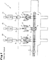
- FIG. 1 shows a plan view of a plant 1 according to the prior art, in which three reel stations 2a, b, c are arranged one behind the other in the rolling direction at the end of a rolling train.
- Each reel station 2a, b, c has a reel mandrel 5, over which a metal collar 4 can be wound.
- the respective metal collars 4 are transported away by transferring the metal collar 4 from the respective reel mandrel 5 to a tilting chair 6 which carries a mandrel bar 7.
- the tilting chair 6 swivels backwards by 90 ° and dips under the collar transfer car 3 shown in the basic position on the left and right.
- This bundle transfer car 3 in turn travels transversely to the rolling direction with the metal collar 4 set down on it and standing in a vertical position over a transport chain 8 which is arranged parallel to the rolling direction.
- a lowering table 9 is provided at the transfer station from the bundle transfer car 3 to the transport chain 8, which lifts the metal bundle 4 from the bundle transfer car 3 and places it on the transport or plate chain 8 as soon as the bundle transfer car 3 has been moved back into its basic position away from the plate chain 8.
- the coils 4 can then be transported away on the plate chain 8 in a vertical axial position parallel to the rolling direction.
- FIG Figure 2 shows a partially sectioned side view through a reel station 2 of the system according to FIG Figure 1 .
- the reel station 2 is shown with the reel mandrel 5 still spread open for winding the hot strip into a metal coil 4.
- a tilting chair 6 is shown both in the receiving position and in a transfer position pivoted about 90 ° with respect to this.
- the tilting chair 6 swivels in the manner shown by about 90 °, so that the metal collar 4 is then oriented vertically for removal.
- the metal collar 6 is placed on the bundle transfer trolley 3 and then set down on the plate chain (not shown) by means of lowering tables when the belt transfer trolley 3 has arrived in its transfer position shown to the left of the plate chain.
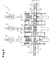
- Figure 3 shows a plan view of a system 1 according to the invention after conversion according to the invention has been carried out in a view from above.
- another transfer and transport device 10 was created for the horizontal transport of metal coils.
- the system 1 created in this way is therefore suitable for transporting metal coils 4 with both a vertical and a horizontal axis position.
- the intended Additional installations 10 are essentially elevated guide rails 12 for one mandrel carriage 13 for each reel station 2.
- metal coils 4 are moved, which were transferred from the reel mandrel 5 to the mandrel carriage 13 without pivoting and thus in a horizontal axial position, above the Level of the bundle transfer car 3 and the tilting chair 6 in the lowered position.
- the metal collar 4 can thus be moved along the elevated guide rail 12 from the respective reel station 2a, b, c and then placed on four-axis coil transport wagons 11, which are movable on rails 12a, b arranged parallel to the transport chain 8 become.
- the rail 12a facing the respective reel stations 2a, b, c for the four-axle coil transport carriage 11 has gaps in order to enable the coil transfer carriage 3 to move from the basic position into the transfer position below or to the side of the plate chain 8.
- the mandrel lift truck 3 can be moved into its basic position behind the plate chain 8 via the guide rails 14a, b in order to enable vertically mounted metal coils 4 to pass.
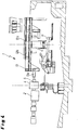
- Figure 4 shows a partially sectioned view of the installation 1 according to FIG Figure 3 .
- the guide rails 12 for the mandrel carriage 13 consist, as shown here, of a running rail system 12 and a counterpressure rail 12b arranged above the running rail system 12a, which serves to ensure that the mandrel carriage 13 is tilted after the metal collar 4 has been transferred from the reel mandrel 5 to the mandrel 13a of the Mandrel carriage 13 is omitted.
- the mandrel carriage 13 moves it by shifting it along the rail system 12 over the four-axle coil transport carriage 11, via which the metal coils 4 can then be transported away in a horizontal position.
- Figure 5 shows the system 1 according to the invention Figure 4 in a view from the front, which makes it clear how the removal of the metal coils 4 is provided in a horizontal position in a plane above the previous installations for the removal of the metal coils in a vertical position.
- the mandrel lift trucks are moved in guide rails 12 onto and away from the reel mandrel (not shown) in order to transfer the metal collar 4 from the reel mandrel to a four-axis coil transport carriage 11.
- These guide rails 12 for the mandrel lift truck 13 are in turn arranged in a raised construction above the level of the rails 14 and the transport chain (not shown) for the removal of metal coils 4 in a vertical axial position.
Landscapes
- Engineering & Computer Science (AREA)
- Mechanical Engineering (AREA)
- Winding, Rewinding, Material Storage Devices (AREA)
- Chain Conveyers (AREA)
- Replacement Of Web Rolls (AREA)
Description
- Die Erfindung betrifft eine Anlage zum Umsetzen und Transport von zu Bunden gewickelten Metallbändern, insbesondere hergestellt aus Warmband, umfassend wenigstens ein Umsetzmittel, vorzugsweise einen Bundaustragewagen, zur Übernahme eines Bundes von einem Haspeldorn und zur Übergabe des Bundes an ein Lademittel der Anlage, wobei ein erstes Lademittel ein Kippstuhl zum Verschwenken des Bundes aus der horizontalen Lage in die vertikale Lage ist, sowie ein erstes Transportmittel zum Abtransport des auf dem Lademittel abgesetzten Bundes in der vertikalen Lage, wobei das erste Transportmittel ein Bundübergabewagen ist. Des Weiteren betrifft die Erfindung ein Verfahren zum Umrüsten einer derartigen Anlage von einer Anlage zum ausschließlichen Abtransport derartiger Coils in vertikaler Lage zu einer Anlage, die in der Lage ist, zumindest einen Teil der Coils auch in horizontaler Lage abzutransportieren.
- Anlagen zum Umsetzen und Transport von zu Bunden gewickelten Metallbändern sind seit Jahrzehnten aus dem Stand der Technik bekannt. Die Erfindung betrifft insbesondere solche Anlagen, die bisher ausschließlich dazu ausgerüstet waren, Coils nach Verlassen der Walzstraße mittels eines Kippstuhls aus der horizontalen Lage innerhalb der Haspelstation in eine vertikale, aufrecht stehende Lage zu verschwenken und diese dann beispielsweise mittels eines Bundübergabewagens auf ein Transportmittel, beispielsweise in der Form einer Transportkette, abzusetzen und schließlich vorzugsweise parallel zur Walzrichtung von der Haspelstation abzutransportieren.
- Es besteht insbesondere bei derartigen Anlagen der Wunsch, bei Bedarf die Coils in horizontaler Lage aus der Haspelstation umzusetzen und ohne Verschwenken in die vertikale Lage abzutransportieren. Ein derartiger Wunsch besteht insbesondere bei dünnen Blechen, insbesondere dünnen Warmbändern, um Kantenbeschädigungen, die beim vertikalen Transport der Metallbunde auftreten können, zu vermeiden.
- Es besteht daher ein Bedarf nach einer Umrüstung bestehender Anlagen auf die Möglichkeit zum horizontalen Abtransport der Metallbunde, vorzugsweise zusammen mit der Möglichkeit, den vertikalen Abtransport ebenfalls weiter durchführen zu können. Darüber hinaus besteht der Wunsch der Anlagenbetreiber, die Umrüstung zeitsparend und ohne die Notwendigkeit für einen langwierigen Stillstand der bestehenden Anlage durchführen zu können.
- Es war daher die Aufgabe der Erfindung, bereits vorhandene Einrichtungen möglichst unverändert weiterbetreiben zu können und vorzugsweise einen großen Anteil der gesamten Produktion, vorzugsweise etwa zwei Drittel der Produktion, mit vertikaler Coilachse auf vorhandenen Kettenförderern transportieren zu können und gleichzeitig unter Verwendung zusätzlicher Einrichtungen einen anderen Teil der Produktion, beispielsweise etwa ein Drittel der Produktion, horizontal austragen zu können, ohne hierbei die vorhandenen Transportmittel einzuschränken, abbauen oder umbauen zu müssen.
- Diese Aufgabe wird im erfindungsgemäßen Sinne mit einer Anlage, umfassend die Merkmale des Anspruchs 1 sowie ein Umrüstverfahren, umfassend die Merkmale des Anspruchs 2, gelöst.
- Erfindungsgemäß wird wenigstens ein zweites Lademittel in hängender Bauweise oberhalb der Ebene für den Kippstuhl und den Bundübergabewagen innerhalb der Anlage angeordnet und gestützt, wobei das zweite Lademittel ein Dornwagen ist, der den Bund in horizontaler Lage verfährt. Hierbei umfasst die Anlage ein zweites Transportmittel zum Abtransport des Bundes in der horizontalen Lage in Form eines Bundtransportwagens. Eine derartig hängende Bauweise kann beispielsweise durch Verbindung der Führungsstruktur mit einer Hallenwand oder Hallendecke erreicht werden. Alternativ und ebenso bevorzugt kann die hängende Bauweise durch eine sogenannte "aufgeständerte Bauweise" erreicht werden, bei der die Führungsstruktur auf dem Boden gelagerten Ständern gelagert ist. Hierdurch wird besonders vorteilhaft erreicht, dass Bewegungen und Zug eines Hallenkrans zu allen Bereichen der Anlage weiterhin nahezu unbegrenzt gegeben ist.
- Vorzugsweise bleiben die vorhandenen Einrichtungen für den vertikalen Transport im Wesentlichen unverändert. Für einen Transport von Bunden in horizontaler Lage muss jedoch der vorhandene Kippstuhl in gekippter Stellung verbleiben. Als Transportmittel wird dann ein Dornwagen eingesetzt, der beispielsweise auf einer aufgeständerten Schienenbahn jeweils vor den Aufhaspelvorrichtungen quer zur Walzrichtung fährt. Der Dorn des Dornwagens hängt dabei unterhalb eines in Schienen geführten Fahrwerks und ist vorzugsweise hydraulisch höhenverstellbar, wodurch er jederzeit die exakte Position des Beladearms des Kippstuhls einnehmen kann.
- Der Bund wird dann mit dem Bundaustragewagen auf den Dorn des Dornwagens aufgeschoben. Nachdem der Bundaustragewagen wieder unter den Haspeldorn gefahren ist, oder nach dem Abziehen des Bundes vom Haspeldorn in einer Ruheposition verharrt, beispielsweise in angehobener oder abgesenkter Stellung, fährt der Dornwagen den Bund über den Kippstuhl und den Ketten-Ladewagen bis zur Mitte der Transportkette.
- Vorzugsweise werden im Bereich mehrerer Haspelvorrichtungen rechts und links der vorhandenen Transportkette Schienen montiert, auf denen ein Bundtransportwagen längs der Transportkette fahren kann. Die Schienen auf der Haspelseite weisen vorzugsweise Unterbrechungen für die Spuren der Ketten-Ladewagen (im Folgenden "Bundübergabewagen" genannt) auf. Diese Unterbrechungen überbrückt der Bundtransportwagen vorzugsweise mit Hilfe von wenigstens vier Rädern, deren Abstand größer als die Schienenunterbrechung ist. Beim Überqueren einer Lücke wird sich deshalb nur eins, maximal zwei der vier Räder im Bereich der Schienenunterbrechung befinden. Der Wagen kann somit die Schienenlücke problemlos queren.
- Dieser Bundtransportwagen wird durch den Dornwagen mit dem Bund oder Coil beladen. Der Dornwagen fährt dann weiter in Richtung Haspelleitstand und zieht den Dorn nach Ablage in die Mulde des Transportwagens aus dem Coil-Auge heraus. Der Bundtransportwagen fährt nun über die Transportkette beispielsweise entgegen der Transportrichtung der Kette weiter bis zum Ende der Haspelgrube.
- Die aufgeständerte Bauweise des erfindungsgemäßen Konzepts der Anlage und die kleinen Schnittstellen zu gegebenenfalls bestehenden Anlagen lassen eine sehr kurze Montage- und Inbetriebnahmezeit zu. Ein großer Teil der neuen Transportanlage kann im Vorfeld, noch während des Betriebs der Warmbandstraße, montiert und eingerichtet werden. Dadurch wird es möglich sein, innerhalb des regelmäßig stattfindenden Wartungsstillstands einer Warmbandstraße die erfindungsgemäße Umrüstung vornehmen zu können.
- Die Erfindung wird nachfolgend unter Bezugnahme auf fünf Figuren näher erläutert. Die Figuren zeigen im Einzelnen:
- Figur 1
- eine schematische Draufsicht auf eine Anlage zum vertikalen Transport von Metallbunden gemäß dem Stand der Technik,
- Figur 2
- eine geschnittene Seitenansicht auf eine Anlage gemäß
Figur 1 nach dem Stand der Technik, - Figur 3
- eine Draufsicht auf eine erfindungsgemäße Anlage nach erfolgter Umrüstung,
- Figur 4
- eine geschnittene Seitenansicht auf die erfindungsgemäße Anlage nach
Figur 4 , und - Figur 5
- eine Draufsicht auf eine erfindungsgemäße Anlage von vorne gesehen.
-
Figur 1 zeigt eine Draufsicht auf eine Anlage 1 gemäß dem Stand der Technik, bei der am Ende einer Walzstraße in Walzrichtung hintereinander drei Haspelstationen 2a, b, c angeordnet sind. Jede Haspelstation 2a, b, c weist einen Haspeldorn 5 auf, über den ein Metallbund 4 aufgewickelt werden kann. Der Abtransport der jeweiligen Metallbunde 4 erfolgt durch Umsetzen des Metallbundes 4 vom jeweiligen Haspeldorn 5 auf einen Kippstuhl 6, der eine Dornstange 7 trägt. Sobald der Metallbund auf der Dornstange 7 des Kippstuhls 6 aufliegt, verschwenkt der Kippstuhl 6 um 90° nach hinten und taucht unter den links und rechts in Grundstellung dargestellten Bundübergabewagen 3 ab. Dieser Bundübergabewagen 3 wiederum fährt quer zur Walzrichtung mit dem auf ihm abgesetzten und in vertikaler Lage stehenden Metallbund 4 über eine Transportkette 8, die parallel zur Walzrichtung angeordnet ist. An der Übernahmestation vom Bundübergabewagen 3 zur Transportkette 8 ist jeweils ein Absenktisch 9 vorgesehen, der den Metallbund 4 vom Bundübergabewagen 3 abhebt und auf die Transport- oder Plattenkette 8 absetzt, sobald der Bundübergabewagen 3 wieder in seine Grundstellung von der Plattenkette 8 entfernt verfahren wurde. Auf der Plattenkette 8 kann dann der Abtransport der Coils 4 in vertikaler Achslage parallel zur Walzrichtung erfolgen. -
Figur 2 zeigt eine teilweise geschnittene Seitenansicht durch eine Haspelstation 2 der Anlage gemäßFigur 1 . Links inFigur 2 ist die Haspelstation 2 mit dem noch aufgespreizten Haspeldorn 5 zur Aufwicklung des Warmbands zu einem Metallbund 4 dargestellt. Rechts an diesen Haspeldorn 5 anschließend ist ein Kippstuhl 6 sowohl in Aufnahmestellung als auch in einer etwa 90° hierzu verschwenkten Übergabestellung dargestellt. Nach Übergabe des Metallbundes 4 vom Haspeldorn 5 auf die Dornstange 7 des Kippstuhls 6 verschwenkt der Kippstuhl 6 in der dargestellten Weise um etwa 90°, so dass dann die Ausrichtung des Metallbundes 4 mit vertikaler Lage zum Abtransport vorliegt. Vom Kippstuhl 6 wird der Metallbund 6 auf den Bundübergabewagen 3 abgelegt und mittels Absenktischen dann auf die Plattenkette (nicht dargestellt) abgesetzt, wenn der Bandübergabewagen 3 in seiner links von der Plattenkette dargestellten Übergabestellung angekommen ist. -
Figur 3 zeigt eine Draufsicht auf eine erfindungsgemäße Anlage 1 nach erfolgter erfindungsgemäßer Umrüstung in einer Ansicht von oben. Zusätzlich zu den Anlagenelementen 2, 3, 5, 6, 7, 8 aus dem Stand der Technik, wie sie beispielsweise inFigur 1 undFigur 2 dargestellt wurden, wurde eine weitere Umsetz- und Transportvorrichtung 10 zum horizontalen Transport von Metallbunden geschaffen. Die so geschaffene Anlage 1 eignet sich daher zum Transport von Metallbunden 4 sowohl mit vertikaler als auch horizontaler Achslage. Die hierfür vorgesehenen zusätzlichen Installationen 10 sind im Wesentlichen aufgeständerte Führungsschienen 12 für jeweils einen Dornwagen 13 für jede Haspelstation 2. Aufgrund der aufgeständerten Bauweise erfolgt eine Bewegung von Metallbunden 4, die vom Haspeldorn 5 auf den Dornwagen 13 ohne Verschwenken und somit in horizontaler Achslage übergeben wurden, oberhalb der Ebene des Bundübergabewagens 3 und des Kippstuhls 6 in abgesenkter Stellung. Der Metallbund 4 kann somit nach Umsetzen auf den Dornwagen 13 entlang der aufgeständerten Führungsschiene 12 von der jeweiligen Haspelstation 2a, b, c fortbewegt werden und anschließend auf Vierachs-Bundtransportwagen 11, die auf parallel zur Transportkette 8 angeordneten Schienen 12a, b beweglich sind, abgesetzt werden. Die den jeweiligen Haspelstationen 2a, b, c zugewandte Schiene 12a für den Vierachs-Bundtransportwagen 11 weist Lücken auf, um weiterhin ein Verfahren des Bundübergabewagens 3 aus der Grundstellung in die Übergabestellung unterhalb bzw. seitlich der Plattenkette 8 zu ermöglichen. Der Dornhubwagen 3 kann über die Führungsschienen 14a, b in seine Grundstellung hinter die Plattenkette 8 hinausbewegt werden, um das Passieren von vertikal gelagerten Metallbunden 4 zu ermöglichen. -
Figur 4 zeigt eine teilweise geschnittene Ansicht der Anlage 1 gemäßFigur 3 . Die Führungsschienen 12 für den Dornwagen 13 bestehen wie hier dargestellt aus einer Fahrschienenanlage 12 sowie einer über der Fahrschienenanlage 12a angeordneten Gegendruckschiene 12b, die dazu dient, dass ein Verkippen des Dornwagens 13 nach erfolgter Übergabe des Metallbundes 4 von dem Haspeldorn 5 auf den Dorn 13a des Dornwagens 13 unterbleibt. Der Dornwagen 13 verbringt nach Übernahme des Metallbundes 4 vom Haspeldorn 5 diesen durch Verschiebung entlang der Fahrschienenanlage 12 über den Vierachs-Bundtransportwagen 11, über den dann der Abtransport der Metallbunde 4 in horizontaler Lage erfolgen kann. -
Figur 5 zeigt die erfindungsgemäße Anlage 1 nachFigur 4 in einer Ansicht von vorne, wodurch verdeutlicht wird, wie der Abtransport der Metallbunde 4 in horizontaler Lage in eine Ebene oberhalb der bisherigen Installationen zum Abtransport der Metallbunde in vertikaler Lage vorgesehen ist. Die Dornhubwagen werden in Führungsschienen 12 auf den Haspeldorn (nicht dargestellt) hin und von diesem weg gefahren, um so den Metallbund 4 vom Haspeldorn auf einen Vierachs-Bundtransportwagen 11 umzusetzen. Diese Führungsschienen 12 für die Dornhubwagen 13 sind wiederum in aufgeständerter Bauweise oberhalb der Ebene der Schienen 14 und der (nicht dargestellten) Transportkette für den Abtransport von Metallbunden 4 in vertikaler Achslage angeordnet.
Claims (2)
- Anlage (1) zum Umsetzen und Transport von zu Bunden (4) gewickelten Metallbändern, insbesondere hergestellt aus Warmband, umfassend wenigstens ein Umsetzmittel zur Übernahme eines Bundes (4) von einem Haspeldorn (5) und zur Übergabe des Bundes (4) an ein Lademittel der Anlage, wobei ein erstes Lademittel ein Kippstuhl (6) zum Verschwenken des Bundes (4) aus der horizontalen Lage in die vertikale Lage ist, sowie ein erstes Transportmittel zum Abtransport des auf dem Lademittel abgesetzten Bundes (4) in der vertikalen Lage, wobei das erste Transportmittel ein Bundübergabewagen (3) ist,
dadurch gekennzeichnet, dass
wenigstens ein zweites Lademittel (13) in hängender Bauweise oberhalb der Ebene für den Kippstuhl und den Bundübergabewagen innerhalb der Anlage angeordnet und gestützt ist, wobei das zweite Lademittel ein Dornwagen ist, der den Bund (4) in horizontaler Lage verfährt, und dass die Anlage ein zweites Transportmittel zum Abtransport des Bundes (4) in der horizontalen Lage umfasst, wobei das zweite Transportmittel ein Bundtransportwagen (11) ist. - Verfahren zum Umrüsten einer Anlage (1) zum Umsetzen und Transport von zu Bunden (4) gewickelten Metallbändern von einer Anlage (1) mit ausschließlich vertikalem Abtransport der Bunde (4) zu einer Anlage (1) gemäß Anspruch 1 mit zumindest teilweisem horizontalen Abtransport der Bunde (4), umfassend die Schritte des Installierens wenigstens eines zweiten Lademittels in Form eines Dornwagens (13) in hängender Bauweise oberhalb der Ebene für den Kippstuhl (6) und den Bundübergabewagen (3) innerhalb der Anlage (1) und des Installierens eines zweiten Transportmittels in Form eines Bundtransportwagens (11) zum horizontalen Abtransport der Bunde (4).
Applications Claiming Priority (2)
| Application Number | Priority Date | Filing Date | Title |
|---|---|---|---|
| DE102014225882 | 2014-12-15 | ||
| PCT/EP2015/079618 WO2016096742A1 (de) | 2014-12-15 | 2015-12-14 | Anlage und verfahren zum umsetzen und transport von coils sowie verfahren zum umrüsten einer derartige anlage |
Publications (2)
| Publication Number | Publication Date |
|---|---|
| EP3233320A1 EP3233320A1 (de) | 2017-10-25 |
| EP3233320B1 true EP3233320B1 (de) | 2021-05-05 |
Family
ID=54884025
Family Applications (1)
| Application Number | Title | Priority Date | Filing Date |
|---|---|---|---|
| EP15813016.1A Active EP3233320B1 (de) | 2014-12-15 | 2015-12-14 | Anlage zum umsetzen und transport von coils sowie verfahren zum umrüsten einer derartigen anlage |
Country Status (6)
| Country | Link |
|---|---|
| EP (1) | EP3233320B1 (de) |
| ES (1) | ES2878088T3 (de) |
| RU (1) | RU2719883C2 (de) |
| TW (1) | TWI602626B (de) |
| UA (1) | UA123667C2 (de) |
| WO (1) | WO2016096742A1 (de) |
Family Cites Families (7)
| Publication number | Priority date | Publication date | Assignee | Title |
|---|---|---|---|---|
| SU1026888A1 (ru) * | 1981-07-13 | 1983-07-07 | Старо-Краматорский машиностроительный завод им.Орджоникидзе | Передающее устройство дл рулонов листового материала |
| SU1667974A1 (ru) * | 1989-08-24 | 1991-08-07 | Производственное объединение "Новокраматорский машиностроительный завод" | Устройство дл передачи рулона с вала барабана моталки на транспортное средство |
| SU1726085A1 (ru) * | 1990-03-15 | 1992-04-15 | Производственное объединение "Новокраматорский машиностроительный завод" | Съемник рулонов |
| JP3783397B2 (ja) * | 1998-04-10 | 2006-06-07 | Jfeスチール株式会社 | コイル移載装置及びそれを用いた移載方法 |
| JP2000343121A (ja) * | 1999-06-07 | 2000-12-12 | Kawasaki Steel Corp | コイル移載装置 |
| CN1231307C (zh) * | 2001-11-02 | 2005-12-14 | 北新建材(集团)有限公司 | 用于钢带连续冲压的生产线 |
| JP2004255404A (ja) * | 2003-02-25 | 2004-09-16 | Nippon Steel Corp | コイルの横孔姿勢搬送装置 |
-
2015
- 2015-12-14 EP EP15813016.1A patent/EP3233320B1/de active Active
- 2015-12-14 ES ES15813016T patent/ES2878088T3/es active Active
- 2015-12-14 UA UAA201707441A patent/UA123667C2/uk unknown
- 2015-12-14 RU RU2017125079A patent/RU2719883C2/ru active
- 2015-12-14 WO PCT/EP2015/079618 patent/WO2016096742A1/de not_active Ceased
- 2015-12-15 TW TW104142215A patent/TWI602626B/zh not_active IP Right Cessation
Also Published As
| Publication number | Publication date |
|---|---|
| WO2016096742A1 (de) | 2016-06-23 |
| RU2719883C2 (ru) | 2020-04-23 |
| ES2878088T3 (es) | 2021-11-18 |
| EP3233320A1 (de) | 2017-10-25 |
| RU2017125079A3 (de) | 2019-01-18 |
| TW201632278A (zh) | 2016-09-16 |
| UA123667C2 (uk) | 2021-05-12 |
| TWI602626B (zh) | 2017-10-21 |
| RU2017125079A (ru) | 2019-01-18 |
Similar Documents
| Publication | Publication Date | Title |
|---|---|---|
| EP2576908B1 (de) | Fahrzeugkombination zum transport von schienen | |
| DE202013102199U1 (de) | Trailerzuganhänger | |
| DE2009520A1 (de) | Vorrichtung zum Bewegen von Lasten, insbesondere Containern | |
| DE102017102930B4 (de) | Hebevorrichtung und Anlage zum Transportieren von Stückgut | |
| DE102012104902B4 (de) | Transportwagen und Verfahren zum vorzugsweise staplerfreien Transport und Umschlag von Transportgut mittels eines solchen Transportwagens | |
| EP2218662A2 (de) | Hubbalkenförderer | |
| DE2836549A1 (de) | Regal | |
| DE3738973C1 (de) | Vorrichtung zum Auswechseln elastischer Superkalander-Walzen | |
| DE102017004410B3 (de) | Behälterwechselvorrichtung | |
| AT18391U1 (de) | Transportsystem für ein Coil | |
| DE102014015963A1 (de) | Gerüstwechselsystem, Wechselwagen und Weiche für ein Gerüstwechselsystem und Walzwerk mit einem Walzblock und einem Gerüstwechselsystem | |
| EP2000384B1 (de) | Service-Arbeitsstand für ein Schienenfahrzeug | |
| DE102017104751B4 (de) | Transportvorrichtung | |
| DE69015461T2 (de) | Fliessband für Unterhalt und Reparatur von Fahrzeug-Aufbauten. | |
| DE2223797C3 (de) | Einrichtung zur Geschwindigkeitsbegrenzung bei einer Fördervorrichtung f Or Walzgut | |
| DE3044953A1 (de) | "vorrichtung zum handhaben von lasten" | |
| WO2016096742A1 (de) | Anlage und verfahren zum umsetzen und transport von coils sowie verfahren zum umrüsten einer derartige anlage | |
| EP3562726B2 (de) | Wartungskorb und verfahren zur wartung einer seilbahn | |
| DE2364502C3 (de) | Einrichtung zum Verlegen von Pipeline-Rohren in Gräben | |
| DE102022128965B4 (de) | Querförderer für Rollgänge | |
| DE4332689C2 (de) | Verfahren und Vorrichtung zum Verlegen von Rohren | |
| EP1234620B1 (de) | Anordnung der, über Kuppeleinrichtungen mit Medienanschlüssen der Ständer von Walzgerüsten verbindbaren, Medienzuleitungen und Verbindungsleitungen | |
| DE2518512A1 (de) | Hochregallager zum transportieren und zwischenlagern von walzwerkserzeugnissen | |
| DE3031825C2 (de) | Vorrichtung zum Übergeben von zu Bunden gewickelten Metallbändern | |
| AT220544B (de) |
Legal Events
| Date | Code | Title | Description |
|---|---|---|---|
| STAA | Information on the status of an ep patent application or granted ep patent |
Free format text: STATUS: THE INTERNATIONAL PUBLICATION HAS BEEN MADE |
|
| PUAI | Public reference made under article 153(3) epc to a published international application that has entered the european phase |
Free format text: ORIGINAL CODE: 0009012 |
|
| STAA | Information on the status of an ep patent application or granted ep patent |
Free format text: STATUS: REQUEST FOR EXAMINATION WAS MADE |
|
| 17P | Request for examination filed |
Effective date: 20170612 |
|
| AK | Designated contracting states |
Kind code of ref document: A1 Designated state(s): AL AT BE BG CH CY CZ DE DK EE ES FI FR GB GR HR HU IE IS IT LI LT LU LV MC MK MT NL NO PL PT RO RS SE SI SK SM TR |
|
| AX | Request for extension of the european patent |
Extension state: BA ME |
|
| DAV | Request for validation of the european patent (deleted) | ||
| DAX | Request for extension of the european patent (deleted) | ||
| GRAP | Despatch of communication of intention to grant a patent |
Free format text: ORIGINAL CODE: EPIDOSNIGR1 |
|
| STAA | Information on the status of an ep patent application or granted ep patent |
Free format text: STATUS: GRANT OF PATENT IS INTENDED |
|
| INTG | Intention to grant announced |
Effective date: 20201207 |
|
| GRAS | Grant fee paid |
Free format text: ORIGINAL CODE: EPIDOSNIGR3 |
|
| GRAA | (expected) grant |
Free format text: ORIGINAL CODE: 0009210 |
|
| STAA | Information on the status of an ep patent application or granted ep patent |
Free format text: STATUS: THE PATENT HAS BEEN GRANTED |
|
| AK | Designated contracting states |
Kind code of ref document: B1 Designated state(s): AL AT BE BG CH CY CZ DE DK EE ES FI FR GB GR HR HU IE IS IT LI LT LU LV MC MK MT NL NO PL PT RO RS SE SI SK SM TR |
|
| REG | Reference to a national code |
Ref country code: GB Ref legal event code: FG4D Free format text: NOT ENGLISH |
|
| REG | Reference to a national code |
Ref country code: CH Ref legal event code: EP |
|
| REG | Reference to a national code |
Ref country code: AT Ref legal event code: REF Ref document number: 1389154 Country of ref document: AT Kind code of ref document: T Effective date: 20210515 |
|
| REG | Reference to a national code |
Ref country code: IE Ref legal event code: FG4D Free format text: LANGUAGE OF EP DOCUMENT: GERMAN |
|
| REG | Reference to a national code |
Ref country code: DE Ref legal event code: R096 Ref document number: 502015014695 Country of ref document: DE |
|
| REG | Reference to a national code |
Ref country code: FI Ref legal event code: FGE |
|
| REG | Reference to a national code |
Ref country code: LT Ref legal event code: MG9D |
|
| PG25 | Lapsed in a contracting state [announced via postgrant information from national office to epo] |
Ref country code: LT Free format text: LAPSE BECAUSE OF FAILURE TO SUBMIT A TRANSLATION OF THE DESCRIPTION OR TO PAY THE FEE WITHIN THE PRESCRIBED TIME-LIMIT Effective date: 20210505 Ref country code: BG Free format text: LAPSE BECAUSE OF FAILURE TO SUBMIT A TRANSLATION OF THE DESCRIPTION OR TO PAY THE FEE WITHIN THE PRESCRIBED TIME-LIMIT Effective date: 20210805 Ref country code: HR Free format text: LAPSE BECAUSE OF FAILURE TO SUBMIT A TRANSLATION OF THE DESCRIPTION OR TO PAY THE FEE WITHIN THE PRESCRIBED TIME-LIMIT Effective date: 20210505 |
|
| REG | Reference to a national code |
Ref country code: ES Ref legal event code: FG2A Ref document number: 2878088 Country of ref document: ES Kind code of ref document: T3 Effective date: 20211118 |
|
| PG25 | Lapsed in a contracting state [announced via postgrant information from national office to epo] |
Ref country code: LV Free format text: LAPSE BECAUSE OF FAILURE TO SUBMIT A TRANSLATION OF THE DESCRIPTION OR TO PAY THE FEE WITHIN THE PRESCRIBED TIME-LIMIT Effective date: 20210505 Ref country code: IS Free format text: LAPSE BECAUSE OF FAILURE TO SUBMIT A TRANSLATION OF THE DESCRIPTION OR TO PAY THE FEE WITHIN THE PRESCRIBED TIME-LIMIT Effective date: 20210905 Ref country code: GR Free format text: LAPSE BECAUSE OF FAILURE TO SUBMIT A TRANSLATION OF THE DESCRIPTION OR TO PAY THE FEE WITHIN THE PRESCRIBED TIME-LIMIT Effective date: 20210806 Ref country code: PT Free format text: LAPSE BECAUSE OF FAILURE TO SUBMIT A TRANSLATION OF THE DESCRIPTION OR TO PAY THE FEE WITHIN THE PRESCRIBED TIME-LIMIT Effective date: 20210906 Ref country code: NO Free format text: LAPSE BECAUSE OF FAILURE TO SUBMIT A TRANSLATION OF THE DESCRIPTION OR TO PAY THE FEE WITHIN THE PRESCRIBED TIME-LIMIT Effective date: 20210805 Ref country code: PL Free format text: LAPSE BECAUSE OF FAILURE TO SUBMIT A TRANSLATION OF THE DESCRIPTION OR TO PAY THE FEE WITHIN THE PRESCRIBED TIME-LIMIT Effective date: 20210505 Ref country code: RS Free format text: LAPSE BECAUSE OF FAILURE TO SUBMIT A TRANSLATION OF THE DESCRIPTION OR TO PAY THE FEE WITHIN THE PRESCRIBED TIME-LIMIT Effective date: 20210505 Ref country code: SE Free format text: LAPSE BECAUSE OF FAILURE TO SUBMIT A TRANSLATION OF THE DESCRIPTION OR TO PAY THE FEE WITHIN THE PRESCRIBED TIME-LIMIT Effective date: 20210505 |
|
| REG | Reference to a national code |
Ref country code: NL Ref legal event code: MP Effective date: 20210505 |
|
| PG25 | Lapsed in a contracting state [announced via postgrant information from national office to epo] |
Ref country code: NL Free format text: LAPSE BECAUSE OF FAILURE TO SUBMIT A TRANSLATION OF THE DESCRIPTION OR TO PAY THE FEE WITHIN THE PRESCRIBED TIME-LIMIT Effective date: 20210505 |
|
| PG25 | Lapsed in a contracting state [announced via postgrant information from national office to epo] |
Ref country code: SM Free format text: LAPSE BECAUSE OF FAILURE TO SUBMIT A TRANSLATION OF THE DESCRIPTION OR TO PAY THE FEE WITHIN THE PRESCRIBED TIME-LIMIT Effective date: 20210505 Ref country code: SK Free format text: LAPSE BECAUSE OF FAILURE TO SUBMIT A TRANSLATION OF THE DESCRIPTION OR TO PAY THE FEE WITHIN THE PRESCRIBED TIME-LIMIT Effective date: 20210505 Ref country code: CZ Free format text: LAPSE BECAUSE OF FAILURE TO SUBMIT A TRANSLATION OF THE DESCRIPTION OR TO PAY THE FEE WITHIN THE PRESCRIBED TIME-LIMIT Effective date: 20210505 Ref country code: DK Free format text: LAPSE BECAUSE OF FAILURE TO SUBMIT A TRANSLATION OF THE DESCRIPTION OR TO PAY THE FEE WITHIN THE PRESCRIBED TIME-LIMIT Effective date: 20210505 Ref country code: EE Free format text: LAPSE BECAUSE OF FAILURE TO SUBMIT A TRANSLATION OF THE DESCRIPTION OR TO PAY THE FEE WITHIN THE PRESCRIBED TIME-LIMIT Effective date: 20210505 Ref country code: RO Free format text: LAPSE BECAUSE OF FAILURE TO SUBMIT A TRANSLATION OF THE DESCRIPTION OR TO PAY THE FEE WITHIN THE PRESCRIBED TIME-LIMIT Effective date: 20210505 |
|
| PGFP | Annual fee paid to national office [announced via postgrant information from national office to epo] |
Ref country code: TR Payment date: 20211210 Year of fee payment: 7 Ref country code: GB Payment date: 20211222 Year of fee payment: 7 Ref country code: FI Payment date: 20211222 Year of fee payment: 7 Ref country code: FR Payment date: 20211224 Year of fee payment: 7 |
|
| REG | Reference to a national code |
Ref country code: DE Ref legal event code: R097 Ref document number: 502015014695 Country of ref document: DE |
|
| PGFP | Annual fee paid to national office [announced via postgrant information from national office to epo] |
Ref country code: BE Payment date: 20211221 Year of fee payment: 7 |
|
| PLBE | No opposition filed within time limit |
Free format text: ORIGINAL CODE: 0009261 |
|
| STAA | Information on the status of an ep patent application or granted ep patent |
Free format text: STATUS: NO OPPOSITION FILED WITHIN TIME LIMIT |
|
| 26N | No opposition filed |
Effective date: 20220208 |
|
| PG25 | Lapsed in a contracting state [announced via postgrant information from national office to epo] |
Ref country code: IS Free format text: LAPSE BECAUSE OF FAILURE TO SUBMIT A TRANSLATION OF THE DESCRIPTION OR TO PAY THE FEE WITHIN THE PRESCRIBED TIME-LIMIT Effective date: 20210905 Ref country code: AL Free format text: LAPSE BECAUSE OF FAILURE TO SUBMIT A TRANSLATION OF THE DESCRIPTION OR TO PAY THE FEE WITHIN THE PRESCRIBED TIME-LIMIT Effective date: 20210505 |
|
| PGFP | Annual fee paid to national office [announced via postgrant information from national office to epo] |
Ref country code: ES Payment date: 20220222 Year of fee payment: 7 |
|
| PG25 | Lapsed in a contracting state [announced via postgrant information from national office to epo] |
Ref country code: MC Free format text: LAPSE BECAUSE OF FAILURE TO SUBMIT A TRANSLATION OF THE DESCRIPTION OR TO PAY THE FEE WITHIN THE PRESCRIBED TIME-LIMIT Effective date: 20210505 |
|
| REG | Reference to a national code |
Ref country code: CH Ref legal event code: PL |
|
| PG25 | Lapsed in a contracting state [announced via postgrant information from national office to epo] |
Ref country code: LU Free format text: LAPSE BECAUSE OF NON-PAYMENT OF DUE FEES Effective date: 20211214 Ref country code: IE Free format text: LAPSE BECAUSE OF NON-PAYMENT OF DUE FEES Effective date: 20211214 |
|
| PG25 | Lapsed in a contracting state [announced via postgrant information from national office to epo] |
Ref country code: LI Free format text: LAPSE BECAUSE OF NON-PAYMENT OF DUE FEES Effective date: 20211231 Ref country code: CH Free format text: LAPSE BECAUSE OF NON-PAYMENT OF DUE FEES Effective date: 20211231 |
|
| PG25 | Lapsed in a contracting state [announced via postgrant information from national office to epo] |
Ref country code: HU Free format text: LAPSE BECAUSE OF FAILURE TO SUBMIT A TRANSLATION OF THE DESCRIPTION OR TO PAY THE FEE WITHIN THE PRESCRIBED TIME-LIMIT; INVALID AB INITIO Effective date: 20151214 |
|
| P01 | Opt-out of the competence of the unified patent court (upc) registered |
Effective date: 20230517 |
|
| PG25 | Lapsed in a contracting state [announced via postgrant information from national office to epo] |
Ref country code: CY Free format text: LAPSE BECAUSE OF FAILURE TO SUBMIT A TRANSLATION OF THE DESCRIPTION OR TO PAY THE FEE WITHIN THE PRESCRIBED TIME-LIMIT Effective date: 20210505 |
|
| GBPC | Gb: european patent ceased through non-payment of renewal fee |
Effective date: 20221214 |
|
| REG | Reference to a national code |
Ref country code: BE Ref legal event code: MM Effective date: 20221231 |
|
| PG25 | Lapsed in a contracting state [announced via postgrant information from national office to epo] |
Ref country code: GB Free format text: LAPSE BECAUSE OF NON-PAYMENT OF DUE FEES Effective date: 20221214 |
|
| PG25 | Lapsed in a contracting state [announced via postgrant information from national office to epo] |
Ref country code: FR Free format text: LAPSE BECAUSE OF NON-PAYMENT OF DUE FEES Effective date: 20221231 Ref country code: BE Free format text: LAPSE BECAUSE OF NON-PAYMENT OF DUE FEES Effective date: 20221231 |
|
| REG | Reference to a national code |
Ref country code: ES Ref legal event code: FD2A Effective date: 20240129 |
|
| PG25 | Lapsed in a contracting state [announced via postgrant information from national office to epo] |
Ref country code: ES Free format text: LAPSE BECAUSE OF NON-PAYMENT OF DUE FEES Effective date: 20221215 |
|
| PG25 | Lapsed in a contracting state [announced via postgrant information from national office to epo] |
Ref country code: MK Free format text: LAPSE BECAUSE OF FAILURE TO SUBMIT A TRANSLATION OF THE DESCRIPTION OR TO PAY THE FEE WITHIN THE PRESCRIBED TIME-LIMIT Effective date: 20210505 Ref country code: FI Free format text: LAPSE BECAUSE OF NON-PAYMENT OF DUE FEES Effective date: 20221214 Ref country code: ES Free format text: LAPSE BECAUSE OF NON-PAYMENT OF DUE FEES Effective date: 20221215 |
|
| PG25 | Lapsed in a contracting state [announced via postgrant information from national office to epo] |
Ref country code: TR Free format text: LAPSE BECAUSE OF NON-PAYMENT OF DUE FEES Effective date: 20221214 Ref country code: MT Free format text: LAPSE BECAUSE OF FAILURE TO SUBMIT A TRANSLATION OF THE DESCRIPTION OR TO PAY THE FEE WITHIN THE PRESCRIBED TIME-LIMIT Effective date: 20210505 |
|
| PGFP | Annual fee paid to national office [announced via postgrant information from national office to epo] |
Ref country code: DE Payment date: 20250429 Year of fee payment: 10 |
|
| PGFP | Annual fee paid to national office [announced via postgrant information from national office to epo] |
Ref country code: IT Payment date: 20250429 Year of fee payment: 10 |
|
| PGFP | Annual fee paid to national office [announced via postgrant information from national office to epo] |
Ref country code: AT Payment date: 20250430 Year of fee payment: 10 |