EP3232159B1 - Vorrichtung zur positionsschätzung eines host-fahrzeugs - Google Patents
Vorrichtung zur positionsschätzung eines host-fahrzeugs Download PDFInfo
- Publication number
- EP3232159B1 EP3232159B1 EP15867690.8A EP15867690A EP3232159B1 EP 3232159 B1 EP3232159 B1 EP 3232159B1 EP 15867690 A EP15867690 A EP 15867690A EP 3232159 B1 EP3232159 B1 EP 3232159B1
- Authority
- EP
- European Patent Office
- Prior art keywords
- host vehicle
- landmark
- distance
- information
- intermediate object
- Prior art date
- Legal status (The legal status is an assumption and is not a legal conclusion. Google has not performed a legal analysis and makes no representation as to the accuracy of the status listed.)
- Active
Links
Images


Classifications
-
- G—PHYSICS
- G01—MEASURING; TESTING
- G01C—MEASURING DISTANCES, LEVELS OR BEARINGS; SURVEYING; NAVIGATION; GYROSCOPIC INSTRUMENTS; PHOTOGRAMMETRY OR VIDEOGRAMMETRY
- G01C21/00—Navigation; Navigational instruments not provided for in groups G01C1/00 - G01C19/00
- G01C21/26—Navigation; Navigational instruments not provided for in groups G01C1/00 - G01C19/00 specially adapted for navigation in a road network
- G01C21/34—Route searching; Route guidance
- G01C21/36—Input/output arrangements for on-board computers
- G01C21/3679—Retrieval, searching and output of POI information, e.g. hotels, restaurants, shops, filling stations, parking facilities
-
- G—PHYSICS
- G01—MEASURING; TESTING
- G01C—MEASURING DISTANCES, LEVELS OR BEARINGS; SURVEYING; NAVIGATION; GYROSCOPIC INSTRUMENTS; PHOTOGRAMMETRY OR VIDEOGRAMMETRY
- G01C21/00—Navigation; Navigational instruments not provided for in groups G01C1/00 - G01C19/00
- G01C21/26—Navigation; Navigational instruments not provided for in groups G01C1/00 - G01C19/00 specially adapted for navigation in a road network
- G01C21/28—Navigation; Navigational instruments not provided for in groups G01C1/00 - G01C19/00 specially adapted for navigation in a road network with correlation of data from several navigational instruments
- G01C21/30—Map- or contour-matching
-
- G—PHYSICS
- G01—MEASURING; TESTING
- G01C—MEASURING DISTANCES, LEVELS OR BEARINGS; SURVEYING; NAVIGATION; GYROSCOPIC INSTRUMENTS; PHOTOGRAMMETRY OR VIDEOGRAMMETRY
- G01C21/00—Navigation; Navigational instruments not provided for in groups G01C1/00 - G01C19/00
- G01C21/26—Navigation; Navigational instruments not provided for in groups G01C1/00 - G01C19/00 specially adapted for navigation in a road network
- G01C21/34—Route searching; Route guidance
- G01C21/36—Input/output arrangements for on-board computers
- G01C21/3626—Details of the output of route guidance instructions
- G01C21/3644—Landmark guidance, e.g. using POIs or conspicuous other objects
-
- G—PHYSICS
- G01—MEASURING; TESTING
- G01C—MEASURING DISTANCES, LEVELS OR BEARINGS; SURVEYING; NAVIGATION; GYROSCOPIC INSTRUMENTS; PHOTOGRAMMETRY OR VIDEOGRAMMETRY
- G01C21/00—Navigation; Navigational instruments not provided for in groups G01C1/00 - G01C19/00
- G01C21/26—Navigation; Navigational instruments not provided for in groups G01C1/00 - G01C19/00 specially adapted for navigation in a road network
- G01C21/34—Route searching; Route guidance
- G01C21/36—Input/output arrangements for on-board computers
- G01C21/3679—Retrieval, searching and output of POI information, e.g. hotels, restaurants, shops, filling stations, parking facilities
- G01C21/3682—Retrieval, searching and output of POI information, e.g. hotels, restaurants, shops, filling stations, parking facilities output of POI information on a road map
-
- G—PHYSICS
- G06—COMPUTING OR CALCULATING; COUNTING
- G06T—IMAGE DATA PROCESSING OR GENERATION, IN GENERAL
- G06T7/00—Image analysis
- G06T7/50—Depth or shape recovery
- G06T7/55—Depth or shape recovery from multiple images
- G06T7/593—Depth or shape recovery from multiple images from stereo images
-
- G—PHYSICS
- G01—MEASURING; TESTING
- G01C—MEASURING DISTANCES, LEVELS OR BEARINGS; SURVEYING; NAVIGATION; GYROSCOPIC INSTRUMENTS; PHOTOGRAMMETRY OR VIDEOGRAMMETRY
- G01C21/00—Navigation; Navigational instruments not provided for in groups G01C1/00 - G01C19/00
- G01C21/26—Navigation; Navigational instruments not provided for in groups G01C1/00 - G01C19/00 specially adapted for navigation in a road network
-
- G—PHYSICS
- G06—COMPUTING OR CALCULATING; COUNTING
- G06T—IMAGE DATA PROCESSING OR GENERATION, IN GENERAL
- G06T2207/00—Indexing scheme for image analysis or image enhancement
- G06T2207/10—Image acquisition modality
- G06T2207/10016—Video; Image sequence
- G06T2207/10021—Stereoscopic video; Stereoscopic image sequence
-
- G—PHYSICS
- G06—COMPUTING OR CALCULATING; COUNTING
- G06T—IMAGE DATA PROCESSING OR GENERATION, IN GENERAL
- G06T2207/00—Indexing scheme for image analysis or image enhancement
- G06T2207/20—Special algorithmic details
- G06T2207/20076—Probabilistic image processing
-
- G—PHYSICS
- G06—COMPUTING OR CALCULATING; COUNTING
- G06T—IMAGE DATA PROCESSING OR GENERATION, IN GENERAL
- G06T2207/00—Indexing scheme for image analysis or image enhancement
- G06T2207/30—Subject of image; Context of image processing
- G06T2207/30244—Camera pose
-
- G—PHYSICS
- G06—COMPUTING OR CALCULATING; COUNTING
- G06T—IMAGE DATA PROCESSING OR GENERATION, IN GENERAL
- G06T2207/00—Indexing scheme for image analysis or image enhancement
- G06T2207/30—Subject of image; Context of image processing
- G06T2207/30248—Vehicle exterior or interior
- G06T2207/30252—Vehicle exterior; Vicinity of vehicle
Definitions
- the present invention relates to a host vehicle position estimation device, and more particularly, to a host vehicle position estimation device that estimates a host vehicle position on a map in a global positioning system (GPS), for example, using images of surroundings of a host vehicle which are photographed using a camera.
- GPS global positioning system
- a car navigation system, an automatic driving system, and the like are widely known as a system using a host vehicle position on a map.
- a global positioning system (GPS) is known as technology which is used for the systems.
- PTL 1 discloses a technique of recognizing a landmark (a landmark which is a sign having a predetermined feature) present on a map from images photographed using a camera and estimating a host vehicle position on the map.
- a self-position estimating device disclosed in PTL 1 includes landmark detecting means that detects a landmark, reliability acquiring means that acquires landmark reliability which is reliability of the landmark detected by the landmark detecting means, and self-position estimating means that estimates a self-position on the basis of a plurality of landmarks detected by the landmark detecting means, and the self-position estimating means sequentially selects the landmarks to be used to estimate the self-position from the landmark having the highest landmark reliability.
- the self-position estimating device disclosed in PTL 1 when a plurality of landmarks are extracted, it is possible to accurately recognize different landmarks and to estimate a self-position with high accuracy.
- the invention is made in consideration of the above-mentioned problem and an object thereof is to provide a host vehicle position estimation device that can accurately estimate a host vehicle position on a map even when no referable landmark is present in an image photographed using a camera.
- a host vehicle position estimation device is set out in claim 1.
- the distance information on a distance to the intermediate object is stored in advance, it is possible to accurately estimate a host vehicle position on a map, for example, even when no referable landmark is present in an image photographed using a camera.
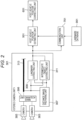
- FIG. 1 is a block diagram illustrating an internal configuration of a first embodiment of a host vehicle position estimation device according to the invention.
- a host vehicle position estimation device 101 illustrated in the drawing is mounted on a vehicle such as an automobile and mainly includes a stereo camera unit 301, a host vehicle position estimating unit 501, a host vehicle position correcting unit 601, and a communication unit 701. The units are connected to each other in an accessible manner.
- a landmark database 901 as a storage unit in which information on types (names) of landmarks and positions thereof on a map (landmark information) is stored in advance is disposed outside the host vehicle position estimation device 101, and the host vehicle position estimation device 101 is connected to the landmark database 901 via the communication unit 701 in an accessible manner.
- the stereo camera unit 301 constituting the host vehicle position estimation device 101 is provided with a plurality of (two in this embodiment) cameras 303 and 305, and the stereo camera unit 301 performs processes of preparing or recognizing a distance image using images acquired by the cameras 303 and 305 and outputs the results to the communication unit 701 and the host vehicle position estimating unit 501.
- a communication standard such as a controller area network (CAN) can be applied to connection of the stereo camera unit 301 to other units.
- CAN controller area network
- the communication unit 701 serves to exchange data with the landmark database 901, receives data stored in the landmark database 901, and transmits the received data to the host vehicle position estimating unit 501.
- the host vehicle position correcting unit 601 corrects the host vehicle position on a map acquired by a global positioning system (GPS) using the estimation result transmitted from the host vehicle position estimating unit 501.
- GPS global positioning system
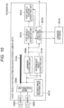
- FIG. 2 illustrates an internal configuration of the stereo camera unit 301 illustrated in FIG. 1 .
- the stereo camera unit 301 serves to recognize an environment around the host vehicle on the basis of image information of an imaging target area on the front side of the vehicle provided with the host vehicle position estimation device 101 and, as illustrated in FIG. 2 , mainly includes a pair of cameras 303 and 305 arranged in a vehicle width direction (a lateral direction) of the host vehicle to face the front side of the vehicle, an image acquiring unit 306, a distance image preparing unit (distance information acquiring unit) 307, a landmark extracting unit 309, an intermediate object extracting unit 311, and a bus 313 capable of accessing images acquired by the two cameras 303 and 305.
- the image acquiring unit 306 of the stereo camera unit 301 acquires images which are synchronously photographed using two cameras 303 and 305 periodically or at an arbitrary timing, and the distance image preparing unit 307 prepares an image (a distance image) having depth information (distance information) using the images (synchronous images) acquired by the image acquiring unit 306.
- the method of preparing the distance image is known well and thus detailed description thereof will not be made herein.
- the landmark extracting unit 309 extracts a landmark from the images using the image acquired by the distance image preparing unit 307 and the images acquired by the two cameras 303 and 305, and outputs information on the extracted landmark to the host vehicle position estimating unit 501 and the communication unit 701.
- a landmark in the invention means, for example, an object which can serve as a sign having a predetermined feature among objects installed on a road and examples thereof include a signboard, a speed sign, a signal, and a building.
- template matching or the like can be used as the method of extracting a landmark.
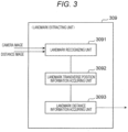
- the landmark extracting unit 309 includes a landmark recognizing unit 3091, a landmark transverse position information acquiring unit 3092, and a landmark distance information acquiring unit 3093.
- the landmark recognizing unit 3091 extracts the above-mentioned landmark from the images and specifies a type (name) of an object which is acquired as the landmark.
- the landmark transverse position information acquiring unit 3092 acquires a transverse position of the extracted landmark with respect to the host vehicle.
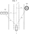
- a transverse position means a length of a perpendicular line (that is, a distance in a transverse direction perpendicular to the traveling direction of the host vehicle) when a perpendicular line is drawn from the position of the extracted landmark to a straight line extending in the traveling direction of the host vehicle (an photographing direction) from the substantial center of the host vehicle (for example, see L1 and L2 in FIG. 7 or L3 in FIG. 9 ).
- a resolution of the transverse position is considered to be more excellent in a stereo camera including a plurality of cameras than in radar and a more accurate transverse position can be acquired using the stereo camera as in this embodiment.
- the landmark distance information acquiring unit 3093 acquires a straight-line distance from the host vehicle to the landmark using the transverse position acquired by the landmark transverse position information acquiring unit 3092 and the image acquired by the distance image preparing unit 307 (for example, see D1 and D2 in FIG. 7 or D3 in FIG. 9 ).
- the landmark extracting unit 309 outputs information on the landmark acquired by the landmark recognizing unit 3091, the landmark transverse position information acquiring unit 3092, or the landmark distance information acquiring unit 3093 to the host vehicle position estimating unit 501 and the communication unit 701.
- an intermediate object in the invention means an object having information (intermediate information) on the name of the landmark among objects around the host vehicle and a distance to the landmark, and examples thereof include a guide sign of a tollgate of an expressway, a guide display board to a restaurant or a theme park, and an exit, a diverging point, or a junction of an expressway.
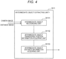
- the intermediate object extracting unit 311 includes an intermediate object recognizing unit 3111, an intermediate object transverse position information acquiring unit 3112, and an intermediate object distance information acquiring unit 3113.
- the intermediate object recognizing unit 3111 extracts the above-mentioned intermediate object from the images and recognizes a name of a landmark included in the intermediate object and a distance to the landmark (for example, as character information).
- the intermediate object transverse position information acquiring unit 3112 acquires a transverse position of the extracted intermediate object with respect to the host vehicle (for example, see L4 in FIG. 9 ), and the intermediate object distance information acquiring unit 3113 acquires a straight-line distance from the host vehicle to the intermediate object using the transverse position acquired by the intermediate object transverse position information acquiring unit 3112 and the image acquired by the distance image preparing unit 307 (for example, see D4 in FIG. 9 ).
- the intermediate object extracting unit 311 outputs information on the intermediate object acquired by the intermediate object recognizing unit 3111, the intermediate object transverse position information acquiring unit 3112, or the intermediate object distance information acquiring unit 3113 to the host vehicle position estimating unit 501 and the communication unit 701.
- the communication unit 701 compares the information on the landmark (particularly, a type of an object acquired as the landmark) transmitted from the landmark extracting unit 309, information on the intermediate object (particularly, a name of a landmark included in the intermediate object) transmitted from the intermediate object extracting unit 311, and information (particularly, a name of the landmark) acquired from the landmark database 901, acquires the position of the landmark on a map or the position of the landmark indicated by the intermediate information of the intermediate object (specifically, the landmark having a name coinciding with the name of the landmark included in the intermediate information) on the map, and transmits the acquired position to the host vehicle position estimating unit 501.
- the host vehicle position estimating unit 501 estimates the position of the host vehicle on the map on the basis of the position of the landmark on the map acquired via the communication unit 701 and the information on the distance of the landmark acquired from (the landmark extracting unit 309 of) the stereo camera unit 301, or estimates the host vehicle position on the map on the basis of the position of the landmark on the map indicated by the intermediate information of the intermediate object acquired via the communication unit 701 and the information on the distance of the intermediate object acquired from (the intermediate object extracting unit 311 of) the stereo camera unit 301.
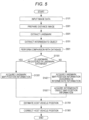
- FIG. 5 illustrates a process flow which is performed by the host vehicle position estimation device 101 illustrated in FIG. 1 .
- the gist of the invention is to acquire a transverse position of the host vehicle and measure a distance (a straight-line distance) on the basis of the information acquired from the cameras 303 and 305 (the stereo camera) in a landmark extracting process which is performed by the landmark extracting unit 309 (S501) and an intermediate object extracting process which is performed by the intermediate object extracting unit 311 (S701) and to measure a distance (straight-line distance), to cause the communication unit 701 to perform a database comparing process (S901) and then to perform a landmark map-position information acquiring process (S1301) and to perform a host vehicle position estimating process (S1701) when the extracted landmark is registered in the landmark database 901, and to perform the host vehicle position estimating process (S1701) using the position information of the intermediate object acquired in an intermediate object map-position information acquiring process (S1501) when the extracted landmark is not registered in the landmark database 9
- the images acquired by the two cameras 303 and 305 are input (S101) and a distance image is prepared using the two images as an input (S301).
- FIG. 6 illustrates an example of a landmark in one image of the images acquired by the two cameras 303 and 305. Since an object and the like installed on a road is extracted as a landmark, a traffic signal LM1 and a speed sign LM2 are extracted as a landmark in the example illustrated in FIG. 6 .
- FIG. 8 illustrates an example of a landmark and an intermediate object in one image of the images acquired by the two cameras 303 and 305.
- FIG. 8 includes a speed sign LM3 as a landmark and a tollgate guide sign MM4 as an intermediate object in which a tollgate as a landmark name and 500 m as a distance to the tollgate are drawn. Accordingly, in the example illustrated in FIG. 8 , the tollgate guide sign MM4 is extracted and the tollgate as the landmark name and 500 m as the distance to the tollgate are acquired as character information in S701.
- S501 and S701 may be performed in a reversed order in the order illustrated in FIG. 5 , or may be performed at the same time (that is, in the same extraction process).
- the landmark acquired in S501 is compared with the database (S901), and it is checked whether the landmark is registered in the landmark database 901 (S1101).
- the position of the landmark on a map is acquired from the landmark database 901 (S1301), and the position of the host vehicle V on the map is estimated (S1701).
- FIG. 7 illustrates a positional relationship between the landmarks in the image illustrated in FIG. 6 and the host vehicle when viewed from the upside.
- lengths L1 and L2 of perpendicular lines drawn from the traffic signal LM1 and the speed sign LM2 to a dotted line C1 drawn in the traveling direction from the substantial center of the host vehicle V indicate transverse positions of the landmarks with respect to the host vehicle which are acquired on the basis of the information acquired from the cameras 303 and 305 (the stereo camera), and lengths D1 and D2 of straight lines drawn from the host vehicle V to the landmarks indicate distances between the host vehicle V and the landmarks.
- the distances acquired using the transverse positions can be obtained more accurately by using the stereo camera. Since the positions of the traffic signal LM1 and the speed sign LM2 on the map are acquired from the landmark database 901, the position of the host vehicle V on the map can be estimated using the positions of the landmarks on the map, the transverse positions with respect to the host vehicle V, and the distances.
- the host vehicle position can be estimated using only one landmark.
- probabilities (scores) of types of the landmarks may be used to recognize the landmarks and the landmark having the greatest score may be used to estimate the host vehicle position.
- a plurality of estimated positions may be output using the plurality of landmarks and an average position thereof may be determined to be the final estimated position, or the final estimated position may be determined by performing weighting based on the scores.
- the position of the landmark described in the intermediate information of the intermediate object acquired in S701 on the map is acquired (S1401)
- the position of the intermediate object on the map is acquired (specified) using the acquisition result (S1501)
- the position of the host vehicle V on the map is estimated (S1701).
- FIG. 9 illustrates a positional relationship between an intermediate object and the host vehicle in the image illustrated in FIG. 8 when viewed from the upside, and specifically illustrates a positional relationship between a tollgate LM5, a speed sign LM3, a tollgate guide sign MM4, and the host vehicle V when viewed from the upside.
- the tollgate LM5 does not appear in the images photographed using the cameras 303 and 305. In the example illustrated in FIG.
- the speed sign LM3 is extracted as a landmark in the landmark extracting process (S501) and the tollgate guide sign MM4 is extracted as an intermediate object in the intermediate object extracting process (S701), but when it is determined as the landmark comparison result that the speed sign LM3 is not registered in the landmark database 901, the host vehicle position on the map is estimated using the tollgate guide sign MM4.
- the position of the tollgate LM5 described in the tollgate guide sign MM4 on the map is acquired from the landmark database 901 (S1401) and the position of the tollgate guide sign MM4 on the map is estimated from the position of the tollgate LM5 on the map and the distance (500 m) to the tollgate described in the tollgate guide sign MM4 (S1501).
- the position of the host vehicle V on the map is estimated from the acquired position of the tollgate guide sign MM4 on the map and a distance D4 of the transverse position L4 of the tollgate guide sign MM4 with respect to the host vehicle V which is acquired using the cameras 303 and 305 (the stereo camera) (S1701).
- the host vehicle position on the map acquired by the GPS or the like is corrected using the estimated position acquired in S1701 (S1901).
- the host vehicle position estimation device 101 can accurately estimate a host vehicle position on a map, for example, even when a referable landmark is not present in an image photographed using a camera, by estimating the host vehicle position on the basis of the intermediate information on a name of a landmark of an intermediate object and a distance to the landmark which is extracted from an image acquired by photographing surroundings of the vehicle, distance information on a distance (a transverse position and a straight-line distance) to the intermediate object, and landmark information on a name and a position of the landmark stored in advance in the landmark database 901.
- FIG. 10 illustrates an internal configuration of a second embodiment of the host vehicle position estimation device according to the invention.
- the functions of the units of a host vehicle position estimation device 101A according to the second embodiment are the same as the functions of the units of the host vehicle position estimation device 101 according to the first embodiment, except that an input and output unit 801A (a unit that exchanges data with a landmark database 901A) corresponding to a host vehicle position estimating unit 501A and a communication unit 701 is integrated in a stereo camera unit 301A in the second embodiment.
- an input and output unit 801A a unit that exchanges data with a landmark database 901A
- a communication unit 701 is integrated in a stereo camera unit 301A in the second embodiment.
- the entire device configuration can be simplified by integrating the functions in the stereo camera unit 301A.
- a distance to an object appearing in an image is acquired using a plurality of images which are synchronously photographed using two cameras in order to secure estimation accuracy, but the distance to the object appearing in an image may be acquired using a plurality of images which are photographed using a single camera (a monocular camera) in a time series in order to simplify the device configuration.
- a radar as a distance information acquiring unit may be mounted on the vehicle and a distance (a straight-line distance) to an object appearing in an image may be acquired on the basis of information acquired from the radar.
- the communication unit 701 or the input and output unit 801A performs the process of comparing the information on a landmark transmitted from the landmark extracting unit 309 or 309A or the information on an intermediate object transmitted from the intermediate object extracting unit 311 or 311A with the information acquired from the landmark database 901 or 901A, but for example, the communication unit 701 or the input and output unit 801A may acquire arbitrary information from the landmark database 901 or 901A periodically or at an appropriate timing and transmit the acquired information to the host vehicle position estimating unit 501 or 501A and the host vehicle position estimating unit 501 or 501A may perform the process of comparing the information on a landmark transmitted from the landmark extracting unit 309 or 309A or the information on an intermediate object transmitted from the intermediate object extracting unit 311 or 311A with the information acquired from the landmark database 901 or 901A.
- the cameras are disposed to face the front side of the vehicle and the host vehicle position on a map is estimated on the basis of image information of an imaging target area on the front side of the vehicle, but the host vehicle position on a map may be estimated on the basis of image information of an imaging target area on the rear side of the vehicle, for example, using cameras disposed to face the rear side of the vehicle.
- the invention is not limited to the first and second embodiments, but can include various modifications.
- the first and second embodiments are described above in detail for the purpose of easily understanding the invention, and the invention is not limited to including all the above-mentioned elements.
- Some elements of a certain embodiment may be replaced with some elements of the other embodiment, or some elements of a certain embodiment may be added to the elements of the other embodiment.
- Some elements of the embodiments may be subjected to addition of some elements, deletion, and substitution, within the scope set out in the appended claims.
Landscapes
- Engineering & Computer Science (AREA)
- Radar, Positioning & Navigation (AREA)
- Remote Sensing (AREA)
- Automation & Control Theory (AREA)
- Physics & Mathematics (AREA)
- General Physics & Mathematics (AREA)
- Computer Vision & Pattern Recognition (AREA)
- Theoretical Computer Science (AREA)
- Traffic Control Systems (AREA)
- Navigation (AREA)
- Instructional Devices (AREA)
- Image Analysis (AREA)
Claims (7)
- Trägerfahrzeugpositionsschätzvorrichtung, die eine Position eines Trägerfahrzeugs unter Verwendung von Orientierungspunktinformationen über Namen und Positionen von Orientierungspunkten, die im Voraus gespeichert werden, schätzt, wobei die Trägerfahrzeugpositionsschätzvorrichtung (101) Folgendes umfasst:eine Bilderfassungseinheit (306), die konfiguriert ist zum Erfassen eines Bilds durch Fotografieren der Umgebung des Trägerfahrzeugs,eine Entfernungsinformationserfassungseinheit (307), die konfiguriert ist zum Erfassen von Entfernungsinformationen über eine Entfernung in einer Fahrtrichtung des Trägerfahrzeugs zu einem beliebigen Objekt, das im Bild erscheint, oder eine Luftlinienentfernung zu einem beliebigen Objekt;eine Zwischenobjektextraktionseinheit (311), die konfiguriert ist zum Extrahieren eines Zwischenobjekts, wobeidas Zwischenobjekt ein Objekt ist, das Zwischeninformationen über einen Namen eines Orientierungspunkts und eine Entfernung zum Orientierungspunkt aufweist, aus dem Bild und zum Erfassen von Entfernungsinformationen über eine Entfernung zum Zwischenobjekt auf der Grundlage der Entfernungsinformationen, die durch die Entfernungsinformationserfassungseinheit (307) erfasst werden, wobeidie Entfernungsinformationen über die Entfernung zum Zwischenobjekt eine Entfernung in einer Querrichtung senkrecht zur Fahrtrichtung des Trägerfahrzeugs zum Zwischenobjekt und die Entfernung in der Fahrtrichtung des Trägerfahrzeugs zum Zwischenobjekt oder die Entfernung in der Querrichtung senkrecht zur Fahrtrichtung des Trägerfahrzeugs zum Zwischenobjekt und eine Luftlinienentfernung zum Zwischenobjekt enthalten; undeine Trägerfahrzeugpositionsschätzeinheit (501), die konfiguriert ist zum Schätzen der Trägerfahrzeugposition auf der Grundlage der Zwischeninformationen des Zwischenobjekts und der Entfernungsinformationen über die Entfernung zum Zwischenobjekt, die durch die Zwischenobjektextraktionseinheit (311) extrahiert werden, und der Orientierungspunktinformationen.
- Trägerfahrzeugpositionsschätzvorrichtung nach Anspruch 1, die ferner Folgendes umfasst:
eine Kommunikationseinheit (701), die konfiguriert ist zum Erfassen von Orientierungspunktinformationen, die den Zwischeninformationen des Zwischenobjekts zugeordnet sind, aus einer Orientierungspunktdatenbank, in der die Orientierungspunktinformationen gespeichert sind. - Trägerfahrzeugpositionsschätzvorrichtung nach Anspruch 1, wobei
die Entfernungsinformationserfassungseinheit (307) die Entfernungsinformationen unter Verwendung von mehreren Bildern erfasst, die unter Verwendung von mehreren Kameras (303, 305), die am Trägerfahrzeug montiert sind, synchron fotografiert werden. - Trägerfahrzeugpositionsschätzvorrichtung nach Anspruch 1, wobei
die Entfernungsinformationserfassungseinheit (307) die Entfernungsinformationen unter Verwendung von mehreren Bildern erfasst, die in einer Zeitreihe mit einer einzelnen Kamera, die am Trägerfahrzeug montiert ist, fotografiert werden. - Trägerfahrzeugpositionsschätzvorrichtung nach Anspruch 1, wobei
die Entfernungsinformationserfassungseinheit (307) die Entfernungsinformationen unter Verwendung von Informationen erfasst, die durch ein Radar, das am Trägerfahrzeug montiert ist, erfasst werden. - Trägerfahrzeugpositionsschätzvorrichtung nach Anspruch 1, wobei
die Trägerfahrzeugpositionsschätzeinheit (501) eine Position eines Orientierungspunkts erfasst, die in den Zwischeninformationen des Zwischenobjekts, die durch die Zwischenobjektextraktionseinheit (311) aus den Orientierungspunktinformationen extrahiert werden, enthalten ist, die Position des Zwischenobjekts festlegt und die Trägerfahrzeugposition aus der festgelegten Position des Zwischenobjekts und den Entfernungsinformationen über die Entfernung zum Zwischenobjekt, die durch die Zwischenobjektextraktionseinheit (311) erfasst werden, schätzt. - Trägerfahrzeugpositionsschätzvorrichtung nach Anspruch 1, die ferner Folgendes umfasst:
eine Trägerfahrzeugpositionskorrektureinheit (601), die konfiguriert ist zum Korrigieren der Trägerfahrzeugposition auf einer Karte, die durch ein globales Positionierungssystem geschätzt wird, auf der Grundlage der Trägerfahrzeugposition, die durch die Trägerfahrzeugpositionsschätzeinheit (501) erfasst wird.
Applications Claiming Priority (2)
| Application Number | Priority Date | Filing Date | Title |
|---|---|---|---|
| JP2014247989 | 2014-12-08 | ||
| PCT/JP2015/082334 WO2016093028A1 (ja) | 2014-12-08 | 2015-11-18 | 自車位置推定装置 |
Publications (3)
| Publication Number | Publication Date |
|---|---|
| EP3232159A1 EP3232159A1 (de) | 2017-10-18 |
| EP3232159A4 EP3232159A4 (de) | 2018-08-15 |
| EP3232159B1 true EP3232159B1 (de) | 2025-06-18 |
Family
ID=56107222
Family Applications (1)
| Application Number | Title | Priority Date | Filing Date |
|---|---|---|---|
| EP15867690.8A Active EP3232159B1 (de) | 2014-12-08 | 2015-11-18 | Vorrichtung zur positionsschätzung eines host-fahrzeugs |
Country Status (4)
| Country | Link |
|---|---|
| US (1) | US10718628B2 (de) |
| EP (1) | EP3232159B1 (de) |
| JP (1) | JP6454726B2 (de) |
| WO (1) | WO2016093028A1 (de) |
Families Citing this family (14)
| Publication number | Priority date | Publication date | Assignee | Title |
|---|---|---|---|---|
| CN109906165A (zh) * | 2016-08-10 | 2019-06-18 | 兹沃公司 | 使用推断的注意力模型经由收集和存储的元数据提供信息的方法和设备 |
| JP6642334B2 (ja) * | 2016-08-25 | 2020-02-05 | トヨタ自動車株式会社 | 車両制御装置 |
| RU2720140C1 (ru) * | 2016-09-27 | 2020-04-24 | Ниссан Мотор Ко., Лтд. | Способ оценки собственной позиции и устройство оценки собственной позиции |
| CN107478228A (zh) * | 2017-07-13 | 2017-12-15 | 杭州品铂科技有限公司 | 一种室内定位方法 |
| USD900133S1 (en) * | 2017-09-27 | 2020-10-27 | Toyota Research Institute, Inc. | Vehicle display screen or portion thereof with a graphical user interface |
| KR20190088119A (ko) * | 2018-01-04 | 2019-07-26 | 삼성전자주식회사 | 차량의 지도 상의 위치를 보정하는 전자 장치 및 방법 |
| EP3740737A1 (de) | 2018-04-03 | 2020-11-25 | Mobileye Vision Technologies Ltd. | Systeme und verfahren zur bestimmung von navigationsparametern |
| US11767024B2 (en) | 2018-10-25 | 2023-09-26 | Samsung Electronics Co., Ltd. | Augmented reality method and apparatus for driving assistance |
| KR102634443B1 (ko) * | 2019-03-07 | 2024-02-05 | 에스케이텔레콤 주식회사 | 차량용 센서의 보정 정보 획득 장치 및 방법 |
| JP6679152B1 (ja) * | 2019-05-27 | 2020-04-15 | 東京海上日動火災保険株式会社 | 事故分析装置、事故分析方法及びプログラム |
| DE102019119095B4 (de) * | 2019-07-15 | 2024-06-13 | Man Truck & Bus Se | Verfahren und Kommunikationssystem zur Unterstützung einer wenigstens teilweise automatischen Fahrzeugsteuerung |
| DE102020115718A1 (de) * | 2020-06-15 | 2021-12-16 | Man Truck & Bus Se | Verfahren zur Bestimmung einer Nutzungsart eines Landmarkenmusters für eine Eigenlokalisierung eines Fahrzeugs, sowie elektronisches Eigenlokalisierungssystem für ein Fahrzeug |
| JP2023144592A (ja) | 2022-03-28 | 2023-10-11 | 株式会社Subaru | 車両位置の生成装置、車両、および、サーバ装置 |
| US11915085B2 (en) * | 2022-05-23 | 2024-02-27 | Zebra Technologies Corporation | Systems and methods for enhanced directionality in RFID portal systems |
Family Cites Families (20)
| Publication number | Priority date | Publication date | Assignee | Title |
|---|---|---|---|---|
| JP2662558B2 (ja) * | 1986-11-01 | 1997-10-15 | 日本電装株式会社 | 現在位置推定装置 |
| JP3848431B2 (ja) * | 1997-04-28 | 2006-11-22 | 本田技研工業株式会社 | 車両位置推定装置と車両位置推定方法、および、走行車線維持装置と走行車線維持方法 |
| DE19842176A1 (de) * | 1998-09-15 | 2000-03-16 | Bosch Gmbh Robert | Verfahren und Vorrichtung zur Verkehrszeichenerkennung und Navigation |
| JP2000097714A (ja) | 1998-09-21 | 2000-04-07 | Sumitomo Electric Ind Ltd | カーナビゲーション装置 |
| US6671615B1 (en) * | 2000-05-02 | 2003-12-30 | Navigation Technologies Corp. | Navigation system with sign assistance |
| US7990286B2 (en) * | 2005-02-14 | 2011-08-02 | Regents Of The University Of Minnesota | Vehicle positioning system using location codes in passive tags |
| US20080243378A1 (en) * | 2007-02-21 | 2008-10-02 | Tele Atlas North America, Inc. | System and method for vehicle navigation and piloting including absolute and relative coordinates |
| JP4985166B2 (ja) * | 2007-07-12 | 2012-07-25 | トヨタ自動車株式会社 | 自己位置推定装置 |
| JP2010190647A (ja) * | 2009-02-17 | 2010-09-02 | Mitsubishi Electric Corp | 車両位置測定装置及び車両位置測定プログラム |
| EP2491344B1 (de) * | 2009-10-22 | 2016-11-30 | TomTom Global Content B.V. | System und verfahren zur fahrzeugnavigation mit seitlichem versatz |
| WO2012011156A1 (ja) * | 2010-07-23 | 2012-01-26 | 三菱電機株式会社 | ナビゲーション装置 |
| US9280711B2 (en) * | 2010-09-21 | 2016-03-08 | Mobileye Vision Technologies Ltd. | Barrier and guardrail detection using a single camera |
| JP5714940B2 (ja) * | 2011-03-04 | 2015-05-07 | 国立大学法人 熊本大学 | 移動体位置測定装置 |
| DE102011118161B3 (de) * | 2011-11-10 | 2013-03-28 | Audi Ag | Verfahren zur Positionsbestimmung |
| WO2013101045A1 (en) * | 2011-12-29 | 2013-07-04 | Intel Corporation | Navigation systems and associated methods |
| US9066085B2 (en) * | 2012-12-13 | 2015-06-23 | Delphi Technologies, Inc. | Stereoscopic camera object detection system and method of aligning the same |
| JP6032017B2 (ja) * | 2013-01-10 | 2016-11-24 | トヨタ自動車株式会社 | 運転制御装置および運転制御方法 |
| EP2950292B1 (de) * | 2013-01-28 | 2024-04-17 | Nec Corporation | Fahrunterstützungsvorrichtung, fahrunterstützungsverfahren und aufzeichnungsmedium zur speicherung eines fahrunterstützungsprogramms |
| JP6289489B2 (ja) * | 2013-10-25 | 2018-03-07 | 三菱電機株式会社 | 移動支援装置及び移動支援方法 |
| JP6225889B2 (ja) * | 2014-11-19 | 2017-11-08 | 株式会社豊田中央研究所 | 車両位置推定装置及びプログラム |
-
2015
- 2015-11-18 EP EP15867690.8A patent/EP3232159B1/de active Active
- 2015-11-18 JP JP2016563586A patent/JP6454726B2/ja active Active
- 2015-11-18 WO PCT/JP2015/082334 patent/WO2016093028A1/ja not_active Ceased
- 2015-11-18 US US15/520,182 patent/US10718628B2/en active Active
Also Published As
| Publication number | Publication date |
|---|---|
| JPWO2016093028A1 (ja) | 2017-09-07 |
| EP3232159A1 (de) | 2017-10-18 |
| US20170314956A1 (en) | 2017-11-02 |
| WO2016093028A1 (ja) | 2016-06-16 |
| JP6454726B2 (ja) | 2019-01-16 |
| EP3232159A4 (de) | 2018-08-15 |
| US10718628B2 (en) | 2020-07-21 |
Similar Documents
| Publication | Publication Date | Title |
|---|---|---|
| EP3232159B1 (de) | Vorrichtung zur positionsschätzung eines host-fahrzeugs | |
| US8209123B2 (en) | Road information generating apparatus, road information generating method, and road information generating program | |
| CN106352867B (zh) | 用于确定车辆自身位置的方法和设备 | |
| KR101919366B1 (ko) | 차량 내부 네트워크 및 영상 센서를 이용한 차량 위치 인식 장치 및 그 방법 | |
| JP6553930B2 (ja) | 車両情報処理装置、及び車両情報処理プログラム | |
| CN105197014B (zh) | 用于识别车辆的行驶车道的装置和方法 | |
| KR102420476B1 (ko) | 차량의 위치 추정 장치, 차량의 위치 추정 방법, 및 이러한 방법을 수행하도록 프로그램된 컴퓨터 프로그램을 저장하는 컴퓨터 판독가능한 기록매체 | |
| US7894632B2 (en) | Apparatus and method of estimating center line of intersection | |
| US10996072B2 (en) | Systems and methods for updating a high-definition map | |
| US10963708B2 (en) | Method, device and computer-readable storage medium with instructions for determining the lateral position of a vehicle relative to the lanes of a road | |
| US20200341150A1 (en) | Systems and methods for constructing a high-definition map based on landmarks | |
| WO2015083538A1 (ja) | 車両位置推定システム,装置,方法、及び、カメラ装置 | |
| CN113316706B (zh) | 路标位置估计设备和方法以及存储被编程为执行该方法的计算机程序的计算机可读记录介质 | |
| CN109211255B (zh) | 用于为具有自动车辆系统的机动车规划路线的方法 | |
| US11410429B2 (en) | Image collection system, image collection method, image collection device, recording medium, and vehicle communication device | |
| US11187815B2 (en) | Method of determining location of vehicle, apparatus for determining location, and system for controlling driving | |
| US20200182629A1 (en) | Method for verifying a digital map of a higher-level automated vehicle, corresponding device and computer program | |
| EP2889198A1 (de) | System und verfahren zur feststellung einer routenänderung mittels bilderkennungsinformationen | |
| US20220318558A1 (en) | Lane-level navigation method and system incorporating adas fine-sensory data | |
| US20180222482A1 (en) | Vehicle control apparatus, vehicle control method, and vehicle control program | |
| JP6933069B2 (ja) | 経路探索装置 | |
| CN108877212A (zh) | 用于建立车辆的环境模型的方法和装置 | |
| JP2012159373A (ja) | データ管理システム、データ管理方法、及びデータ管理プログラム | |
| CN115808179A (zh) | 一种交通信息获取方法、装置及存储介质 | |
| WO2017023187A1 (ru) | Способ и система определения средней скорости транспортного средства |
Legal Events
| Date | Code | Title | Description |
|---|---|---|---|
| STAA | Information on the status of an ep patent application or granted ep patent |
Free format text: STATUS: THE INTERNATIONAL PUBLICATION HAS BEEN MADE |
|
| PUAI | Public reference made under article 153(3) epc to a published international application that has entered the european phase |
Free format text: ORIGINAL CODE: 0009012 |
|
| STAA | Information on the status of an ep patent application or granted ep patent |
Free format text: STATUS: REQUEST FOR EXAMINATION WAS MADE |
|
| 17P | Request for examination filed |
Effective date: 20170710 |
|
| AK | Designated contracting states |
Kind code of ref document: A1 Designated state(s): AL AT BE BG CH CY CZ DE DK EE ES FI FR GB GR HR HU IE IS IT LI LT LU LV MC MK MT NL NO PL PT RO RS SE SI SK SM TR |
|
| AX | Request for extension of the european patent |
Extension state: BA ME |
|
| DAV | Request for validation of the european patent (deleted) | ||
| DAX | Request for extension of the european patent (deleted) | ||
| A4 | Supplementary search report drawn up and despatched |
Effective date: 20180713 |
|
| RIC1 | Information provided on ipc code assigned before grant |
Ipc: G09B 29/10 20060101ALI20180709BHEP Ipc: G08G 1/0969 20060101ALI20180709BHEP Ipc: G01C 21/30 20060101AFI20180709BHEP |
|
| STAA | Information on the status of an ep patent application or granted ep patent |
Free format text: STATUS: EXAMINATION IS IN PROGRESS |
|
| 17Q | First examination report despatched |
Effective date: 20210422 |
|
| RAP3 | Party data changed (applicant data changed or rights of an application transferred) |
Owner name: HITACHI ASTEMO, LTD. |
|
| GRAP | Despatch of communication of intention to grant a patent |
Free format text: ORIGINAL CODE: EPIDOSNIGR1 |
|
| STAA | Information on the status of an ep patent application or granted ep patent |
Free format text: STATUS: GRANT OF PATENT IS INTENDED |
|
| INTG | Intention to grant announced |
Effective date: 20250220 |
|
| RIN1 | Information on inventor provided before grant (corrected) |
Inventor name: NAGASAKI, TAKESHI Inventor name: KIDO, HIDEAKI Inventor name: SHIINA, YUHI |
|
| GRAS | Grant fee paid |
Free format text: ORIGINAL CODE: EPIDOSNIGR3 |
|
| GRAA | (expected) grant |
Free format text: ORIGINAL CODE: 0009210 |
|
| STAA | Information on the status of an ep patent application or granted ep patent |
Free format text: STATUS: THE PATENT HAS BEEN GRANTED |
|
| AK | Designated contracting states |
Kind code of ref document: B1 Designated state(s): AL AT BE BG CH CY CZ DE DK EE ES FI FR GB GR HR HU IE IS IT LI LT LU LV MC MK MT NL NO PL PT RO RS SE SI SK SM TR |
|
| REG | Reference to a national code |
Ref country code: GB Ref legal event code: FG4D |
|
| REG | Reference to a national code |
Ref country code: CH Ref legal event code: EP |
|
| REG | Reference to a national code |
Ref country code: DE Ref legal event code: R096 Ref document number: 602015091851 Country of ref document: DE |
|
| REG | Reference to a national code |
Ref country code: CH Ref legal event code: EP |
|
| REG | Reference to a national code |
Ref country code: IE Ref legal event code: FG4D |
|
| PG25 | Lapsed in a contracting state [announced via postgrant information from national office to epo] |
Ref country code: FI Free format text: LAPSE BECAUSE OF FAILURE TO SUBMIT A TRANSLATION OF THE DESCRIPTION OR TO PAY THE FEE WITHIN THE PRESCRIBED TIME-LIMIT Effective date: 20250618 |
|
| REG | Reference to a national code |
Ref country code: LT Ref legal event code: MG9D |
|
| PG25 | Lapsed in a contracting state [announced via postgrant information from national office to epo] |
Ref country code: GR Free format text: LAPSE BECAUSE OF FAILURE TO SUBMIT A TRANSLATION OF THE DESCRIPTION OR TO PAY THE FEE WITHIN THE PRESCRIBED TIME-LIMIT Effective date: 20250919 Ref country code: NO Free format text: LAPSE BECAUSE OF FAILURE TO SUBMIT A TRANSLATION OF THE DESCRIPTION OR TO PAY THE FEE WITHIN THE PRESCRIBED TIME-LIMIT Effective date: 20250918 |
|
| PG25 | Lapsed in a contracting state [announced via postgrant information from national office to epo] |
Ref country code: BG Free format text: LAPSE BECAUSE OF FAILURE TO SUBMIT A TRANSLATION OF THE DESCRIPTION OR TO PAY THE FEE WITHIN THE PRESCRIBED TIME-LIMIT Effective date: 20250618 |
|
| PG25 | Lapsed in a contracting state [announced via postgrant information from national office to epo] |
Ref country code: HR Free format text: LAPSE BECAUSE OF FAILURE TO SUBMIT A TRANSLATION OF THE DESCRIPTION OR TO PAY THE FEE WITHIN THE PRESCRIBED TIME-LIMIT Effective date: 20250618 |
|
| PG25 | Lapsed in a contracting state [announced via postgrant information from national office to epo] |
Ref country code: RS Free format text: LAPSE BECAUSE OF FAILURE TO SUBMIT A TRANSLATION OF THE DESCRIPTION OR TO PAY THE FEE WITHIN THE PRESCRIBED TIME-LIMIT Effective date: 20250918 |
|
| REG | Reference to a national code |
Ref country code: NL Ref legal event code: MP Effective date: 20250618 |
|
| PG25 | Lapsed in a contracting state [announced via postgrant information from national office to epo] |
Ref country code: LV Free format text: LAPSE BECAUSE OF FAILURE TO SUBMIT A TRANSLATION OF THE DESCRIPTION OR TO PAY THE FEE WITHIN THE PRESCRIBED TIME-LIMIT Effective date: 20250618 |
|
| PG25 | Lapsed in a contracting state [announced via postgrant information from national office to epo] |
Ref country code: NL Free format text: LAPSE BECAUSE OF FAILURE TO SUBMIT A TRANSLATION OF THE DESCRIPTION OR TO PAY THE FEE WITHIN THE PRESCRIBED TIME-LIMIT Effective date: 20250618 |
|
| PG25 | Lapsed in a contracting state [announced via postgrant information from national office to epo] |
Ref country code: PT Free format text: LAPSE BECAUSE OF FAILURE TO SUBMIT A TRANSLATION OF THE DESCRIPTION OR TO PAY THE FEE WITHIN THE PRESCRIBED TIME-LIMIT Effective date: 20251020 |
|
| REG | Reference to a national code |
Ref country code: AT Ref legal event code: MK05 Ref document number: 1804537 Country of ref document: AT Kind code of ref document: T Effective date: 20250618 |