EP3231954A1 - Längeneinstellbarer abhänger für das verankern einer abgehängten unterdecke - Google Patents
Längeneinstellbarer abhänger für das verankern einer abgehängten unterdecke Download PDFInfo
- Publication number
- EP3231954A1 EP3231954A1 EP17000612.6A EP17000612A EP3231954A1 EP 3231954 A1 EP3231954 A1 EP 3231954A1 EP 17000612 A EP17000612 A EP 17000612A EP 3231954 A1 EP3231954 A1 EP 3231954A1
- Authority
- EP
- European Patent Office
- Prior art keywords
- profile
- connecting part
- hanger according
- easily deformable
- holes
- Prior art date
- Legal status (The legal status is an assumption and is not a legal conclusion. Google has not performed a legal analysis and makes no representation as to the accuracy of the status listed.)
- Granted
Links
- 238000004873 anchoring Methods 0.000 title claims abstract description 4
- 238000005452 bending Methods 0.000 claims description 10
- 238000010276 construction Methods 0.000 description 5
- 238000009434 installation Methods 0.000 description 3
- 229910000831 Steel Inorganic materials 0.000 description 2
- 238000006073 displacement reaction Methods 0.000 description 2
- 239000010959 steel Substances 0.000 description 2
- 230000009471 action Effects 0.000 description 1
- 230000008901 benefit Effects 0.000 description 1
- 230000008859 change Effects 0.000 description 1
- 238000011900 installation process Methods 0.000 description 1
- 239000000463 material Substances 0.000 description 1
- 239000002184 metal Substances 0.000 description 1
- 238000000034 method Methods 0.000 description 1
- 238000000465 moulding Methods 0.000 description 1
- 230000008569 process Effects 0.000 description 1
- 239000007787 solid Substances 0.000 description 1
- 230000007704 transition Effects 0.000 description 1
- 230000003313 weakening effect Effects 0.000 description 1
Images


Classifications
-
- E—FIXED CONSTRUCTIONS
- E04—BUILDING
- E04B—GENERAL BUILDING CONSTRUCTIONS; WALLS, e.g. PARTITIONS; ROOFS; FLOORS; CEILINGS; INSULATION OR OTHER PROTECTION OF BUILDINGS
- E04B9/00—Ceilings; Construction of ceilings, e.g. false ceilings; Ceiling construction with regard to insulation
- E04B9/18—Means for suspending the supporting construction
- E04B9/183—Means for suspending the supporting construction having a lower side adapted to be connected to a channel of the supporting construction
-
- E—FIXED CONSTRUCTIONS
- E04—BUILDING
- E04B—GENERAL BUILDING CONSTRUCTIONS; WALLS, e.g. PARTITIONS; ROOFS; FLOORS; CEILINGS; INSULATION OR OTHER PROTECTION OF BUILDINGS
- E04B9/00—Ceilings; Construction of ceilings, e.g. false ceilings; Ceiling construction with regard to insulation
- E04B9/18—Means for suspending the supporting construction
- E04B9/20—Means for suspending the supporting construction adjustable
- E04B9/205—Means for suspending the supporting construction adjustable by means of a resilient clip
-
- E—FIXED CONSTRUCTIONS
- E04—BUILDING
- E04B—GENERAL BUILDING CONSTRUCTIONS; WALLS, e.g. PARTITIONS; ROOFS; FLOORS; CEILINGS; INSULATION OR OTHER PROTECTION OF BUILDINGS
- E04B9/00—Ceilings; Construction of ceilings, e.g. false ceilings; Ceiling construction with regard to insulation
- E04B9/18—Means for suspending the supporting construction
- E04B9/20—Means for suspending the supporting construction adjustable
-
- H—ELECTRICITY
- H01—ELECTRIC ELEMENTS
- H01L—SEMICONDUCTOR DEVICES NOT COVERED BY CLASS H10
- H01L2224/00—Indexing scheme for arrangements for connecting or disconnecting semiconductor or solid-state bodies and methods related thereto as covered by H01L24/00
- H01L2224/01—Means for bonding being attached to, or being formed on, the surface to be connected, e.g. chip-to-package, die-attach, "first-level" interconnects; Manufacturing methods related thereto
- H01L2224/02—Bonding areas; Manufacturing methods related thereto
- H01L2224/023—Redistribution layers [RDL] for bonding areas
Definitions
- the invention relates to a length-adjustable hanger for anchoring a suspended false ceiling.
- Hanger in the sense of this document are those elements by means of which a suspended false ceiling is attached to a supporting structure of the building, typically a raw ceiling.
- the load-bearing structure is at a distance to this above the lower ceiling.
- the hangers hang vertically from the supporting structure to the false ceiling and are burdened by the weight of the false ceiling on train.
- the hangers are adjustable in length, so that the lower ceiling can be arranged regardless of unevenness of the supporting structure in any case horizontally at the desired height.
- a disadvantage of the construction is that it must be handled with some effort around the sub-ceiling, or when the sub-ceiling is very heavy, for some applications, especially too little safe against unintentional misalignment or loosening.
- the hanger against pressure load in its longitudinal direction is hardly kink resistant.
- the second operating principle is for example in the DE 1280528 B shown.
- Hangers based on this functional principle are commonly referred to - and furthermore also in this application - as "nonius hangers".
- Two connecting parts each have an extension formed as a metal profile, wherein these profiles are typically U-profiles, are aligned parallel to one another, and rest longitudinally with overlapping longitudinal region against one another.
- Both profiles each have an in-line hole, wherein the holes are through holes through a profile wall and lie side by side in the profile direction and wherein the holes are arranged with respect to the position in the cross-sectional areas of the profiles so that holes in one profile can be aligned with holes in the other profile.
- the pitch of the holes in one profile is slightly different than that in the other profile, so that when longitudinal displacement of the profiles together in rapid succession different pairs of two mutually aligned holes change.
- total length of the connecting parts a pin is inserted through a pair of then mutually aligned holes in the two profiles, so that further longitudinal displacement of the profiles and thus the connecting parts is blocked together.
- the inventor has set itself the task of improving a nonius hanger provided for fixing a suspended false ceiling to a load-bearing structure arranged above it in relation to known constructions in such a way that it becomes possible with a single size of Nonius pendants to cover all common height distances between false ceiling and load-bearing structure.
- the bendable profile can therefore, if it is formed so long that it can bridge even the largest distances between sub-ceiling and load-bearing structure, be reshaped so that it can be applied even at very small distances between sub-ceiling and supporting structure.
- the easily deformable profile is so soft deformable around bending axes lying parallel to its profile direction, that its profile shape length section for length section by hand from a flat strip shape is deformable.
- the profile does not need to be well bendable from the outset to axes that are normal to the profile direction. This achieves high positional stability of the false ceiling.
- the deformation of the profile shape should be achievable by forces in the size range of 40 N to 200 N which are applied over a small area (approximately 1 cm 2 attack surface).
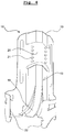
- the lower part of the upper connecting part 1 is originally a straight angle profile 2.
- the angle section 1 is curved in its lower longitudinal region 4 both from the vertical out, as well as deformed in its profile shape in a continuous transition to a flat strip 5.
- the angle section 2 has a row of holes 6 running in profile direction. This row of holes 6 runs in the flat strip 5. In Fig. 1 the rows of holes 6 in the region of the flat strip 5 are symbolized by a dotted line.
- the wall thickness of the angle profile 2 in the joint area of the two angle legs by a notch along the profile 7th weakened.
- the angle profile 2 consists of a soft steel sheet with just under a mm wall thickness; in the region of the notch 7, the wall thickness is reduced to about 0.5 mm.
- the desirable weakening of the angle profile 2 in the joint area of the two angle legs can also take place in a different way than by means of a single notch 7. For example, a trough-like depression could be embossed in the sheet, or a grid of apertures could be drilled or punched in the sheet.
- the lower connecting part 3 is formed in sections in its upper longitudinal region as a straight angle section 8. In installation situation, this angle profile 8 is vertically aligned and in the raised angle range between its two legs while the angle profile 2 of the upper connecting part 1 is in undeformed state.
- the angle section 8 has on each of its two legs extending in the profile direction regular row of holes 9, wherein the pitch of the hole center distances is slightly different than in the rows of holes 6 at the upper connecting part 1, so between the two rows of holes 6, 9, the vernier connection is formed from the prior art known.
- the lower connecting part 3 further has an angle-shaped support tab 10, which adjoins the bottom of the angle section 8 and is slightly displaced by this in the raised angle range, so that between the support bracket 10 and the angle section 8 an open gap 11 is formed, orientalwelchen in installation situation the angle section 2 of the upper connecting part 1 passes therethrough.
- the support tab 10 has the function of preventing deformation of the angle profile 2 in that longitudinal region with which this rests on the angle section 8.
- a respective extension 14 which for connection with a - not shown - profile of the ceiling to be fixed is used.
- This profile typically has a roughly C-profile shape, and the extensions abut the inwardly curved side profile legs.
- the rigid connecting part need not necessarily be provided with edges or surfaces on which the deformable profile of the second connecting part is deformed.
- the necessary deformation could also be done by unguided molding by hand or using a separate stop member for bending.
- a simpler design of the rigid connection part would face a loss of comfort during the assembly process.
- the profile to be deformed does not necessarily have to be an angle profile. Also suitable are U-profiles, or profiles with arcuate cross-sectional shape.
- the deformable profile even before the deformation during assembly be flat strip-shaped, so that it is practically not changed in the assembly in its cross-sectional shape, but only to the profile direction normal lying axes is bent.
- the advantage of an even simpler installation process is the disadvantage that the profile is so easy to bend in one that the risk of unwanted bends and thus undesirable moving the lower ceiling increases.
- Fig. 3 and Fig. 4 show a second, particularly advantageous combination of upper connecting part 15 and lower connecting part 16th Fig. 3 additionally shows a pin 17, which by aligned hole pairs of the rows of holes of the two connecting parts 15, 16th
- the upper longitudinal region of the connecting part 15 is again a straight profile, in this case with an approximately C-shaped cross-sectional area.
- the profile forming the upper connecting part 15 is bent towards the profile side at which the cross-sectional area of the profile has a groove, whereby the profile shape also changes to that of a flat strip.
- the lower connecting part 16 has in that height region at which the deformation of the upper connecting part 15 takes place a curved surface 18 which bears against the inside of the curvature of the upper connecting part during the bending operation and supports it against kinking.
- the lower connecting part 16 again has a trained as a straight profile 19 area, and a contrast normal to the profile direction shifted but otherwise aligned profiled support tab 20.
- the upper, vertically aligned, non-curved longitudinal portion of the upper connecting part 15 is between the straight profile 19 and the support bracket 20 can be pushed through and supported by these parts against curvature.
- the belonging to the lower connecting part 16 rows of holes 21 are in the construction according to Fig. 3 and Fig. 4 formed in the support tab 20.
Landscapes
- Engineering & Computer Science (AREA)
- Architecture (AREA)
- Physics & Mathematics (AREA)
- Electromagnetism (AREA)
- Civil Engineering (AREA)
- Structural Engineering (AREA)
- Finishing Walls (AREA)
- Joining Of Building Structures In Genera (AREA)
Abstract
Description
- Die Erfindung betrifft einen längeneinstellbaren Abhänger für das Verankern einer abgehängten Unterdecke.
- Abhänger im Sinne dieses Dokumentes sind jene Elemente, über welche eine abgehängten Unterdecke an einer tragenden Struktur des Gebäudes - typischerweise einer Rohdecke - befestigt ist. Dabei befindet sich die tragende Struktur in einem Abstand zu dieser oberhalb der Unterdecke. Die Abhänger hängen vertikal von der tragenden Struktur zur Unterdecke und sind durch das Gewicht der Unterdecke auf Zug belastet. Die Abhänger sind in ihrer Länge einstellbar, damit die Unterdecke unabhängig von Unebenheiten der tragenden Struktur jedenfalls horizontal in der gewünschten Höhe angeordnet werden kann.
- Bei den meisten angewendeten Bauweisen für längeneinstellbare Abhänger ist eines der beiden folgenden Funktionsprinzipien angewandt:
- Das erste Funktionsprinzip ist beispielsweise in der
DE 3539373 A1 und derDE 102011013986 A1 gezeigt. Ein gerader, sehr schlanker Teil, typischerweise aus sehr starrem Draht, ragt durch zwei Durchbrüche einer auf Biegung elastisch vorgespannten, etwa U-förmig gekrümmten Biegefeder hindurch. Durch die elastische Vorspannung verkanntet sich der schlanke Teil an den Rändern der Durchbrüche und ist damit an der Biegefeder kraftschlüssig fixiert. Wenn die Biegefeder händisch etwas zusammengedrückt wird, sind der schlanke Teil und die Biegefeder in Längsrichtung des schlanken Teils gegeneinander verschiebbar. Damit ist eine schnelle und stufenlose Längeneinstellbarkeit der überlappenden Länge aus einem mit der Biegefeder starr verbundenen Teil und dem schlanken Teil ermöglicht. - Nachteilig an der Bauweise ist, dass sie für einige Anwendungen, insbesondere dann, wenn an der Unterdecke mit Kraftaufwand herum hantiert werden muss, oder wenn die Unterdecke sehr schwer ist, als zu wenig sicher gegen unbeabsichtigtes Verstellen oder Lösen gilt. Insbesondere ist der Abhänger gegen Druckbelastung in seiner Längsrichtung kaum knickfest.
- Das zweite Funktionsprinzip ist beispielsweise in der
DE 1280528 B gezeigt. Abhänger die auf diesem Funktionsprinzip basieren, werden gemeinhin - und des Weiteren auch in dieser Anmeldung - als "Noniusabhänger" bezeichnet. Zwei Verbindungsteile haben jeweils einen als Metallprofil ausgebildeten Fortsatz, wobei diese Profile typischerweise U-Profile sind, parallel zueinander ausgerichtet sind, und mit überlappendem Längsbereich längsverschiebbar aneinander anliegen. Beide Profile weisen jeweils eine Reihenlochbohrung auf, wobei die Löcher Durchgangslöcher durch eine Profilwand sind und in Profilrichtung nebeneinander liegen und wobei die Löcher bezüglich der Position in den Querschnittsflächen der Profile so angeordnet sind, dass Löcher im einen Profil mit Löchern im anderen Profil fluchten können. Der Rasterabstand der Löcher im einen Profil ist geringfügig anders als jener im anderen Profil, sodass bei Längsverschiebung der Profile aneinander in schneller Folge verschiedene Paare von zwei zueinander fluchtenden Löchern wechseln. Bei für die jeweilige Montagesituation passenden Gesamtlänge der Verbindungsteile wird durch ein Paar von dann zueinander fluchtenden Löchern in den beiden Profilen ein Stift hindurchgesteckt, sodass weitere Längsverschiebbarkeit der Profile und damit der Verbindungsteile aneinander blockiert ist. - Abhänger dieser Bauweise, also Noniusabhänger, sind fest, auch knickfest, und sicher gegen unbeabsichtigtes Verstellen, unabhängig davon, wie an der abgehängten Unterdecke herumhantiert wird. Nachteilig an der Bauweise ist, dass je Paar von Verbindungsteilen nur ein relativ kleiner Bereich der überlappenden Gesamtlänge abgedeckt werden kann, sodass man in der Praxis nicht mit jeweils einer Größe von Verbindungsteilen auskommt, sondern entweder viele Größen von Verbindungsteilen braucht, oder lange Verbindungsteile bei Bedarf aufwändig kürzen muss.
- Von diesem Stand der Technik ausgehend hat sich der Erfinder die Aufgabe gestellt, einen für das Befestigen einer abgehängten Unterdecke an einer über dieser angeordneten tragenden Struktur vorgesehen Nonius-Abhänger gegenüber bekannten Bauweisen dahingehend zu verbessern, dass es damit möglich wird, mit einer einzigen Baugröße von Noniusabhängern, alle gängigen Höhenabstände zwischen Unterdecke und tragender Struktur abzudecken.
- Für das Lösen der Aufgabe wird vorgeschlagen, von den beiden Profilen, welche jeweils eine Lochreihe aufweisen, ein Profil so leicht verformbar auszubilden, dass bei der Montage ein überstehender Längsbereich händisch von der vertikalen Ausrichtung in die horizontale Ausrichtung gebogen werden kann - womit er im Raum zwischen Unterdecke und tragender Konstruktion Platz findet ohne zu stören.
- Das biegbare Profil kann daher auch dann, wenn es so lang ausgebildet ist, dass es auch größte Abstände zwischen Unterdecke und tragender Struktur überbrücken kann, so umgeformt werden, dass es auch bei kleinsten Abständen zwischen Unterdecke und tragender Struktur angewendet werden kann.
- Eine passende Auslegung von Material, Profilform und Wandstärke des zu verformenden Profils, damit dieses von Hand aus ausreichend leicht gebogen werden kann, ist ihm Rahmen des fachmännischen Handelns durch Versuch ohne weiteres möglich, weswegen hier nicht sehr vertiefend darauf eingegangen wird. Als quantitative Zielvorstellung für die Bemessung kann typischerweise davon ausgegangen werden, dass das Profil bei Biegebeanspruchung als einseitig eingespannter Träger mit quer zur Profilrichtung ausgerichteter Punktlast am freien Trägerende bei einer Trägerlänge von 20 cm durch eine Kraft im Größenbereich von 40 N bis 400 N um 90° aus seiner ursprünglichen Ausrichtung biegbar sein sollte.
- In einer besonders bevorzugten Ausführungsform ist das leicht verformbare Profil um zu seiner Profilrichtung parallel liegende Biegeachsen so weich verformbar, dass seine Profilform Längenabschnitt für Längenabschnitt von Hand aus zu flacher Streifenform umformbar ist.
- Durch diese Verformbarkeit braucht das Profil nicht von vornherein auch um Achsen gut biegbar zu sein, welche normal zur Profilrichtung liegen. Damit wird hohe Positionsstabilität der Unterdecke erreicht.
- Als quantitative Zielvorstellung für die Bemessung kann typischerweise davon ausgegangen werden, dass die Verformung der Profilform durch kleinflächig (etwa 1 cm2 Angriffsfläche) aufzubringende Kräfte im Größenbereich von 40 N bis 200 N erzielbar sein sollte.
- Die Erfindung wird an Hand von stilisierten Zeichnungen der für das Verständnis der Erfindung wesentlichen Einzelteile eines beispielhaften erfindungsgemäßen Abhängers veranschaulicht. Aus Gründen der Anschaulichkeit sind die beiden Verbindungsteile nicht gemeinsam in einer Zeichnung dargestellt, sondern jeweils für sich allen.
-
Fig. 1 : zeigt in Schrägrissansicht den unteren Teil des oberen Verbindungsteiles in jener Form die er in eingebautem Zustand haben kann. -
Fig. 2 : zeigt in Schrägrissansicht den unteren Verbindungsteil. - Der untere Teil des oberen Verbindungsteils 1 ist ursprünglich ein gerades Winkelprofil 2. Nach dem erfindungsgemäßen Zusammenbau mit dem in
Fig. 2 skizzierten unteren Verbindungsteil 3 ist das Winkelprofil 1 in seinem unteren Längsbereich 4 sowohl aus der Vertikalen heraus gekrümmt, als auch in seiner Profilform in einem kontinuierlichen Übergang zu einem flachen Streifen 5 umgeformt. - An jedem seiner beiden Schenkel weist das Winkelprofil 2 eine in Profilrichtung verlaufende Lochreihe 6 auf. Diese Lochreihe 6 verläuft in den flachen Streifen 5. In
Fig. 1 sind die Lochreihen 6 im Bereich des flachen Streifens 5 durch eine punktierte Linien symbolisiert. - Damit das (plastische) Umformen des unteren Längsbereichs 4 des Winkelprofils 2 von der Winkelprofilform in einen flachen Streifen 5 bei der Montage des Abhängers werkzeuglos möglich sein soll, ist die Wandstärke des Winkelprofils 2 im Stoßbereich der beiden Winkelschenkel durch eine entlang des Profils verlaufende Kerbe 7 geschwächt.
Typischerweise besteht das Winkelprofil 2 aus einem weichen Stahlblech mit knapp einem mm Wandstärke; im Bereich der Kerbe 7 ist die Wandstärke auf etwa 0,5 mm verringert.
Die wünschenswerte Schwächung des Winkelprofils 2 im Stoßbereich der beiden Winkelschenkel kann auch auf eine andere Art als mittels einer einzigen Kerbe 7 erfolgen. Beispielsweise könnte eine Muldenartige Vertiefung in das Blech geprägt sein, oder es könnte ein Raster von Durchbrüchen in das Blech gebohrt oder gestanzt sein. - Am nicht dargestellten oberen Endbereich des Winkelprofils 2 befindet sich in Einbausituation irgendein Verbindungsbeschlag über welchen das Winkelprofil 2 mit der tragenden Struktur des Gebäudes verbunden ist.
- Der in
Fig. 2 skizzierte untere Verbindungsteil 3, besteht typischerweise aus gestanztem und gebogenem Stahlblech, welches fester sein kann als jenes vom Winkelprofil 2, da es bestimmungsgemäß weder bei der Montage noch danach noch verformt werden soll. - Der untere Verbindungsteil 3 ist in seinem oberen Längsbereich abschnittsweise als gerades Winkelprofil 8 ausgebildet. In Einbausituation ist diese Winkelprofil 8 vertikal ausgerichtet und im erhaben Winkelbereich zwischen seinen beiden Schenkeln liegt dabei das Winkelprofil 2 des oberen Verbindungsteils 1 in unverformten Zustand an.
- Das Winkelprofil 8 weist an jedem seiner beiden Schenkel eine in Profilrichtung verlaufende regelmäßige Lochreihe 9 auf, bei welcher das Rastermaß der Lochmittenabstände geringfügig anders ist als bei den Lochreihen 6 am oberen Verbindungsteil 1, sodass zwischen den beiden Lochreihen 6, 9 die Nonius-Verbindung wie aus dem Stand der Technik bekannt gebildet wird.
- Der untere Verbindungsteil 3 weist weiters eine winkelprofilförmige Stützlasche 10 auf, welche unten an das Winkelprofil 8 anschließt und von diesem etwas in dessen erhabenen Winkelbereich verschoben ist, sodass zwischen der Stützlasche 10 und dem Winkelprofil 8 ein offener Spalt 11 gebildet wird, durchwelchen hindurch in Einbausituation das Winkelprofil 2 des oberen Verbindungsteil 1 hindurch verläuft. Die Stützlasche 10 hat die Funktion, Verformung des Winkelprofils 2 in jenem Längsbereich mit dem dieses am Winkelprofil 8 anliegt, zu verhindern.
- An die Stützlasche 10 unten schließen am unteren Verbindungsteil zwei Auflaufkanten 12 an, an welchen bestimmungsgemäß bei der Montage die Innenseiten der Schenkel des Winkelprofils 2 des oberen Verbindungsteils anliegen, sodass sie beim Schieben des Winkelprofils 2 entlang des unteren Verbindungsteils 3 nach unten hin, umgeformt werden, sodass seine Winkelschenkel zunehmend in die Parallele zueinander verformt werden und das ganze Winkelprofil mehr und mehr in die Horizontale gebogen wird. An die Auflaufkanten 12 schließt unten jeweils eine Blechlasche 13 an, an welchen bei der Montage der untere Längsbereich 4 des Winkelprofils 2 des oberen Verbindungsteils 1 weiter in die in
Fig. 1 skizzierte Form umgeformt wird. - An seinem seitlichen unteren Bereich ist der untere Verbindungsteil 3 mit jeweils einem Fortsatz 14 versehen, welcher zur Verbindung mit einem - nicht dargestellten - Profil der zu befestigenden Unterdecke dient. Dieses Profil hat typischerweise etwa C-Profilform, und die Fortsätze liegen innen an den einwärts gekrümmten seitlichen Profilschenkeln an.
- An im Rahmen des Erfindungsgedankens liegenden Verallgemeinerungen zu der skizzierten beispielhaften Ausführung seien ohne Anspruch auf Vollständigkeit kurz genannt bzw. verdeutlicht:
- Bezüglich der Funktionsweise können oberer und unterer Verbindungsteil auch vertauscht sein. Das heißt es kann auch der obere Verbindungsteil zur Gänze starr sein und der untere Verbindungsteil ein zu verformendes Profil aufweisen.
- Der starre Verbindungsteil braucht nicht zwangsweise mit Kanten oder Flächen versehen sein, an welchen das verformbare Profil des zweiten Verbindungsteils verformt wird. Das notwendige Verformen könnte auch durch ungeführtes Verformen von Hand aus oder unter Anwendung eines separaten Anschlagteiles für das Biegen erfolgen. Einer einfacheren Bauform des starren Verbindungsteils stünde ein Verlust an Komfort beim Montagevorgang gegenüber.
- Das zu verformende Profil braucht nicht unbedingt ein Winkelprofil zu sein. Gut anwendbar sind auch U-Profile, oder Profile mit bogenartiger Querschnittsform.
- Prinzipiell kann das verformbare Profil auch schon vor der Verformung bei der Montage flach streifenförmig sein, sodass es bei der Montage in seiner Querschnittsform praktisch nicht verändert wird, sondern nur um zur Profilrichtung normal liegende Achsen gebogen wird. Dem Vorteil eines noch einfacheren Montagevorganges steht der Nachteil gegenüber, dass das Profil in einer so leicht zu biegen ist, dass die Gefahr von unerwünschten Biegungen und damit unerwünschtem Verschieben der Unterdecke steigt.
-
Fig. 3 undFig. 4 zeigen eine zweite, besonders vorteilhafte Kombination aus oberem Verbindungsteil 15 und unterem Verbindungsteil 16.Fig. 3 zeigt zusätzlich auch einen Stift 17, welcher durch zueinander fluchtende Lochpaare der Lochreihen der beiden Verbindungsteile 15, 16. - Der obere Längsbereich des Verbindungsteils 15 ist wiederum ein gerades Profil, in diesem Fall mit etwa C-förmiger Querschnittsfläche. Am unteren Höhenbereich des unteren Verbindungsteils 16 ist das den oberen Verbindungsteil 15 bildende Profil zu jener Profilseite hin an welcher die Querschnittsfläche des Profils eine Nut aufweist, in die Horizontale umgebogen, wobei sich auch die Profilform zu der eines flachen Streifen umwandelt. Der untere Verbindungsteil 16 weist in jenem Höhenbereich an welchem die Umformung des oberen Verbindungsteils 15 stattfindet eine gekrümmte Fläche 18 auf, welche während des Biegenvorgangs an der Innenseite der Krümmung des oberen Verbindungsteils anliegt und diesen gegen Abknicken abstützt.
- Wie unter Zuhilfenahme von
Fig. 4 erkennbar ist, weist der untere Verbindungsteil 16 wiederum einen als gerades Profil 19 ausgebildeten Bereich auf, und eine dagegen etwas normal zur Profilrichtung verschobene ansonsten aber gleich ausgerichtete profilförmige Stützlasche 20. Der obere, vertikal ausgerichtete, nicht gekrümmte Längsbereich des oberen Verbindungsteils 15 ist zwischen dem geraden Profil 19 und der Stützlasche 20 durchsteckbar und durch diese Teile gegen Krümmung gestützt. Die zum unteren Verbindungsteil 16 gehörende Lochreihen 21 sind bei der Bauweise gemäßFig. 3 undFig. 4 in der Stützlasche 20 ausgebildet. - Wie aus dem Stand der Technik bekannt, weist der untere Verbindungsteil 16 an seinem unteren Längsbereich zwei mit jeweils einem Schlitz versehene Wandbereiche 22 auf, mit Hilfe derer er bestimmungsgemäß sehr gut fest und spielfrei an einer Profilschiene mit C-förmiger, nach oben offener Querschnittsfläche verbindbar ist.
Claims (10)
- Als Noniusabhänger ausgebildeter, längeneinstellbare Abhänger für das Verankern einer abgehängten Unterdecke an einer über dieser angeordneten tragenden Struktur, welcher einen oberen und Verbindungsteil (1, 15) und einen unteren Verbindungsteil (3, 16) aufweist, welche jeweils einen als gerades Profil (2, 8, 19) ausgebildeten Bereich aufweisen, die aneinander anliegen, dabei mit mindestens jeweils einem Paar von Lochreihen (6, 9, 21) aneinander liegen bei denen der Lochabstand unterschiedlich ist und wobei ein Stift (17) durch ein Paar von miteinander fluchtenden Löchern aus beiden Lochreihen (6, 9, 21) steckbar ist,
dadurch gekennzeichnet, dass
ein Profil (2) aus der Gruppe der beiden Profile (2, 8, 19) so leicht verformbar ist, dass bei der Montage ein überstehender Längsbereich händisch von der vertikalen Ausrichtung in die horizontale Ausrichtung biegbar ist. - Abhänger nach Anspruch 1, dadurch gekennzeichnet, dass das Profil (2, 8, 19) eine von der flachen Querschnittsform abweichende Profilform aufweist.
- Abhänger nach Anspruch 2, dadurch gekennzeichnet, dass das Profil (2, 8, 19) Winkel-, U- oder Bogenquerschnittform aufweist.
- Abhänger nach einem der Ansprüche 1 bis 3, dadurch gekennzeichnet, dass das leicht verformbare Profil (2) zwei Teilbereiche aufweist, wobei der eine Teilbereich gerade und vertikal ausgerichtet ist und der zweite Teilbereich abgeflacht und aus der Vertikalen heraus gekrümmt ist.
- Abhänger nach Anspruch 3 oder 4, dadurch gekennzeichnet, dass leicht verformbare Profil (2) um zu seiner Profilrichtung parallel liegende Biegeachsen so weich verformbar ist, dass seine Profilform Längenabschnitt für Längenabschnitt von Hand aus zu flacher Streifenform umformbar ist.
- Abhänger nach einem der Ansprüche 1 bis 5, dadurch gekennzeichnet, dass jener Verbindungsteil (3, 16), von welchem das leicht verformbare Profil (2) nicht Teil ist, eine Längsführung für das leicht verformbare Profil (2) aufweist, durch welche dieses Profil (2) im Zuge der Montage hindurchführbar ist.
- Abhänger nach Anspruch 6, dadurch gekennzeichnet, dass die Längsführung eine Stützlasche (10, 20) umfasst.
- Abhänger nach einem der Ansprüche 1 bis 7, dadurch gekennzeichnet, dass jener Verbindungsteil (3, 16), von welchem das leicht verformbare Profil (2) nicht Teil ist, eine gekrümmte Fläche (18) aufweist, an welcher das leicht verformbare Profil (2) mit der Innenseite seines gekrümmten Längsbereiches anliegt.
- Abhänger nach einem der Ansprüche 1 bis 8, dadurch gekennzeichnet, dass das leicht verformbare Profil (2) ein Winkelprofil ist, welches im Stoßbereich der beiden Winkelschenkel geschwächt ist.
- Abhänger nach Anspruch 9, dadurch gekennzeichnet, dass das Profil (2) im Stoßbereich der beiden Winkelschenkel eine in Profillängsrichtung verlaufende Kerbe (7) aufweist.
Applications Claiming Priority (1)
| Application Number | Priority Date | Filing Date | Title |
|---|---|---|---|
| ATA192/2016A AT518245B1 (de) | 2016-04-12 | 2016-04-12 | Längeneinstellbarer Abhänger für das Verankern einer abgehängten Unterdecke |
Publications (2)
| Publication Number | Publication Date |
|---|---|
| EP3231954A1 true EP3231954A1 (de) | 2017-10-18 |
| EP3231954B1 EP3231954B1 (de) | 2021-05-26 |
Family
ID=58544684
Family Applications (1)
| Application Number | Title | Priority Date | Filing Date |
|---|---|---|---|
| EP17000612.6A Active EP3231954B1 (de) | 2016-04-12 | 2017-04-11 | Längeneinstellbarer abhänger für das verankern einer abgehängten unterdecke |
Country Status (2)
| Country | Link |
|---|---|
| EP (1) | EP3231954B1 (de) |
| AT (1) | AT518245B1 (de) |
Families Citing this family (1)
| Publication number | Priority date | Publication date | Assignee | Title |
|---|---|---|---|---|
| CN111062087B (zh) * | 2020-01-10 | 2022-06-21 | 西南交通大学 | 地下工程中基于位移差/梯度的锚固件长度设计方法 |
Citations (4)
| Publication number | Priority date | Publication date | Assignee | Title |
|---|---|---|---|---|
| DE1280528B (de) * | 1966-10-29 | 1968-10-17 | Friedrich Frueh | Verstellbarer Abhaenger fuer die Tragschienen einer Unterdecke od. dgl. |
| DE29700387U1 (de) * | 1997-01-09 | 1997-05-15 | Richter-System GmbH & Co KG, 64347 Griesheim | Abhänger |
| EP1916351A1 (de) * | 2006-10-26 | 2008-04-30 | Knauf Insaat ve Yapi Elemanlari Sanayi ve Ticaret A.S. | Zweiteiliger Aufhänger |
| FR2937987A1 (fr) * | 2008-11-04 | 2010-05-07 | Novovis Soc | Dispositif de fixation d'une suspente pour faux-plafond. |
Family Cites Families (4)
| Publication number | Priority date | Publication date | Assignee | Title |
|---|---|---|---|---|
| FR2727451B1 (fr) * | 1994-11-24 | 1997-01-31 | Isobox Henry | Procede pour l'etablissement d'un faux plafond en sous face d'un plancher a entrevous en matiere synthetique expansee, suspente correspondante et entrevous equipe d'une telle suspente |
| NL1010882C2 (nl) * | 1998-12-23 | 2000-06-26 | Maars Holding Bv | Ophangsamenstel voor het aan een vast plafond ophangen van een profiel voor het dragen van panelen. |
| EP1201841B1 (de) * | 2000-10-25 | 2006-10-18 | Richter-System GmbH & Co. KG | Direktabhänger für C-Schienen |
| DE202006002616U1 (de) * | 2006-02-18 | 2006-04-13 | Vogl, Erich R. | Vorrichtung zur Herstellung von abgehängten Decken |
-
2016
- 2016-04-12 AT ATA192/2016A patent/AT518245B1/de not_active IP Right Cessation
-
2017
- 2017-04-11 EP EP17000612.6A patent/EP3231954B1/de active Active
Patent Citations (4)
| Publication number | Priority date | Publication date | Assignee | Title |
|---|---|---|---|---|
| DE1280528B (de) * | 1966-10-29 | 1968-10-17 | Friedrich Frueh | Verstellbarer Abhaenger fuer die Tragschienen einer Unterdecke od. dgl. |
| DE29700387U1 (de) * | 1997-01-09 | 1997-05-15 | Richter-System GmbH & Co KG, 64347 Griesheim | Abhänger |
| EP1916351A1 (de) * | 2006-10-26 | 2008-04-30 | Knauf Insaat ve Yapi Elemanlari Sanayi ve Ticaret A.S. | Zweiteiliger Aufhänger |
| FR2937987A1 (fr) * | 2008-11-04 | 2010-05-07 | Novovis Soc | Dispositif de fixation d'une suspente pour faux-plafond. |
Also Published As
| Publication number | Publication date |
|---|---|
| AT518245A4 (de) | 2017-09-15 |
| AT518245B1 (de) | 2017-09-15 |
| EP3231954B1 (de) | 2021-05-26 |
Similar Documents
| Publication | Publication Date | Title |
|---|---|---|
| WO2019048362A1 (de) | Winkelverbinder für montageschienen | |
| EP3027541A1 (de) | Einstellbarer tragrollenstuhl in einer fã-rderbandanlage und einstellbare anordnung hierzu | |
| DE2652481A1 (de) | Abhaengeelement fuer ein traggerippe zur halterung von zwischendeckenelementen | |
| EP1049226A2 (de) | Vorrichtung zum Verbinden von Kabelkanal-Abschnitten | |
| DE102011013986A1 (de) | Zusammenbauteil sowie Abhängevorrichtung für Tragschienen und Verfahren zu deren Herstellung | |
| EP3231954B1 (de) | Längeneinstellbarer abhänger für das verankern einer abgehängten unterdecke | |
| DE4335000C2 (de) | U-förmiges Verbindungselement zur Verbindung von C-Profilschienen aus Metall | |
| DE3247506C2 (de) | Gasdichte Unterdecke | |
| EP2236687A1 (de) | Knotenabhänger für ein abgehängtes Deckensystem | |
| DE20108187U1 (de) | Universalverbinder | |
| DE102015108298B4 (de) | Steckbarer Gitterrost und Verfahren zu seiner Herstellung | |
| DE102015203098B4 (de) | Laufschienenführung | |
| DE2510946B1 (de) | Kreuzverbindungsstueck fuer ein traggerippe einer unterdecke | |
| DE102018107020A1 (de) | Haltesystem für eine Kabeltrasse | |
| DE102022110103B3 (de) | Befestigungsklammer für ein Kabeltragsystem sowie Kabeltragsystem mit einer solchen Befestigungsklammer | |
| DE3523741C2 (de) | Tragkonstruktion für abgehängte Decken | |
| DE102021120323B4 (de) | Endseitig einseitig abgestützter Ausleger für ein Kabeltragsystem | |
| EP3757305B1 (de) | Arbeitsraum | |
| DE9306127U1 (de) | Geräteeinbaudose für Installationskanäle | |
| DE2405388C3 (de) | Querprofilschelle für Unterdecken | |
| DE202009005341U1 (de) | Deckenabhänger | |
| DE202010008118U1 (de) | Halter sowie Anordnung umfassend einen solchen Seilhalter und ein Trägerprofil | |
| EP4270695A1 (de) | Befestigungsklammer für ein langelement, insbesondere ein kabeltragsystem sowie kabeltragsystem mit einer solchen befestigungsklammer | |
| DE202005001921U1 (de) | Schienenaggregat, vorgefertigte Einheit zur Herstellung eines Schienenaggregates und Verbindungselement für ein Schienenaggregat | |
| DE102004061953B4 (de) | Abhänger für Schienen einer Tragkonstruktion |
Legal Events
| Date | Code | Title | Description |
|---|---|---|---|
| PUAI | Public reference made under article 153(3) epc to a published international application that has entered the european phase |
Free format text: ORIGINAL CODE: 0009012 |
|
| STAA | Information on the status of an ep patent application or granted ep patent |
Free format text: STATUS: THE APPLICATION HAS BEEN PUBLISHED |
|
| AK | Designated contracting states |
Kind code of ref document: A1 Designated state(s): AL AT BE BG CH CY CZ DE DK EE ES FI FR GB GR HR HU IE IS IT LI LT LU LV MC MK MT NL NO PL PT RO RS SE SI SK SM TR |
|
| AX | Request for extension of the european patent |
Extension state: BA ME |
|
| STAA | Information on the status of an ep patent application or granted ep patent |
Free format text: STATUS: REQUEST FOR EXAMINATION WAS MADE |
|
| 17P | Request for examination filed |
Effective date: 20180321 |
|
| RBV | Designated contracting states (corrected) |
Designated state(s): AL AT BE BG CH CY CZ DE DK EE ES FI FR GB GR HR HU IE IS IT LI LT LU LV MC MK MT NL NO PL PT RO RS SE SI SK SM TR |
|
| GRAP | Despatch of communication of intention to grant a patent |
Free format text: ORIGINAL CODE: EPIDOSNIGR1 |
|
| STAA | Information on the status of an ep patent application or granted ep patent |
Free format text: STATUS: GRANT OF PATENT IS INTENDED |
|
| INTG | Intention to grant announced |
Effective date: 20201218 |
|
| GRAS | Grant fee paid |
Free format text: ORIGINAL CODE: EPIDOSNIGR3 |
|
| GRAA | (expected) grant |
Free format text: ORIGINAL CODE: 0009210 |
|
| STAA | Information on the status of an ep patent application or granted ep patent |
Free format text: STATUS: THE PATENT HAS BEEN GRANTED |
|
| AK | Designated contracting states |
Kind code of ref document: B1 Designated state(s): AL AT BE BG CH CY CZ DE DK EE ES FI FR GB GR HR HU IE IS IT LI LT LU LV MC MK MT NL NO PL PT RO RS SE SI SK SM TR |
|
| RAP1 | Party data changed (applicant data changed or rights of an application transferred) |
Owner name: BAUSTOFF + METALL GMBH |
|
| REG | Reference to a national code |
Ref country code: GB Ref legal event code: FG4D Free format text: NOT ENGLISH |
|
| RIN1 | Information on inventor provided before grant (corrected) |
Inventor name: PEER, ROBERT |
|
| REG | Reference to a national code |
Ref country code: CH Ref legal event code: EP |
|
| REG | Reference to a national code |
Ref country code: DE Ref legal event code: R096 Ref document number: 502017010435 Country of ref document: DE |
|
| REG | Reference to a national code |
Ref country code: AT Ref legal event code: REF Ref document number: 1396354 Country of ref document: AT Kind code of ref document: T Effective date: 20210615 |
|
| REG | Reference to a national code |
Ref country code: IE Ref legal event code: FG4D Free format text: LANGUAGE OF EP DOCUMENT: GERMAN |
|
| REG | Reference to a national code |
Ref country code: LT Ref legal event code: MG9D |
|
| PG25 | Lapsed in a contracting state [announced via postgrant information from national office to epo] |
Ref country code: BG Free format text: LAPSE BECAUSE OF FAILURE TO SUBMIT A TRANSLATION OF THE DESCRIPTION OR TO PAY THE FEE WITHIN THE PRESCRIBED TIME-LIMIT Effective date: 20210826 Ref country code: HR Free format text: LAPSE BECAUSE OF FAILURE TO SUBMIT A TRANSLATION OF THE DESCRIPTION OR TO PAY THE FEE WITHIN THE PRESCRIBED TIME-LIMIT Effective date: 20210526 Ref country code: FI Free format text: LAPSE BECAUSE OF FAILURE TO SUBMIT A TRANSLATION OF THE DESCRIPTION OR TO PAY THE FEE WITHIN THE PRESCRIBED TIME-LIMIT Effective date: 20210526 Ref country code: LT Free format text: LAPSE BECAUSE OF FAILURE TO SUBMIT A TRANSLATION OF THE DESCRIPTION OR TO PAY THE FEE WITHIN THE PRESCRIBED TIME-LIMIT Effective date: 20210526 |
|
| REG | Reference to a national code |
Ref country code: NL Ref legal event code: MP Effective date: 20210526 |
|
| PG25 | Lapsed in a contracting state [announced via postgrant information from national office to epo] |
Ref country code: RS Free format text: LAPSE BECAUSE OF FAILURE TO SUBMIT A TRANSLATION OF THE DESCRIPTION OR TO PAY THE FEE WITHIN THE PRESCRIBED TIME-LIMIT Effective date: 20210526 Ref country code: SE Free format text: LAPSE BECAUSE OF FAILURE TO SUBMIT A TRANSLATION OF THE DESCRIPTION OR TO PAY THE FEE WITHIN THE PRESCRIBED TIME-LIMIT Effective date: 20210526 Ref country code: PL Free format text: LAPSE BECAUSE OF FAILURE TO SUBMIT A TRANSLATION OF THE DESCRIPTION OR TO PAY THE FEE WITHIN THE PRESCRIBED TIME-LIMIT Effective date: 20210526 Ref country code: NO Free format text: LAPSE BECAUSE OF FAILURE TO SUBMIT A TRANSLATION OF THE DESCRIPTION OR TO PAY THE FEE WITHIN THE PRESCRIBED TIME-LIMIT Effective date: 20210826 Ref country code: PT Free format text: LAPSE BECAUSE OF FAILURE TO SUBMIT A TRANSLATION OF THE DESCRIPTION OR TO PAY THE FEE WITHIN THE PRESCRIBED TIME-LIMIT Effective date: 20210927 Ref country code: GR Free format text: LAPSE BECAUSE OF FAILURE TO SUBMIT A TRANSLATION OF THE DESCRIPTION OR TO PAY THE FEE WITHIN THE PRESCRIBED TIME-LIMIT Effective date: 20210827 Ref country code: IS Free format text: LAPSE BECAUSE OF FAILURE TO SUBMIT A TRANSLATION OF THE DESCRIPTION OR TO PAY THE FEE WITHIN THE PRESCRIBED TIME-LIMIT Effective date: 20210926 Ref country code: LV Free format text: LAPSE BECAUSE OF FAILURE TO SUBMIT A TRANSLATION OF THE DESCRIPTION OR TO PAY THE FEE WITHIN THE PRESCRIBED TIME-LIMIT Effective date: 20210526 |
|
| PG25 | Lapsed in a contracting state [announced via postgrant information from national office to epo] |
Ref country code: NL Free format text: LAPSE BECAUSE OF FAILURE TO SUBMIT A TRANSLATION OF THE DESCRIPTION OR TO PAY THE FEE WITHIN THE PRESCRIBED TIME-LIMIT Effective date: 20210526 |
|
| PG25 | Lapsed in a contracting state [announced via postgrant information from national office to epo] |
Ref country code: SM Free format text: LAPSE BECAUSE OF FAILURE TO SUBMIT A TRANSLATION OF THE DESCRIPTION OR TO PAY THE FEE WITHIN THE PRESCRIBED TIME-LIMIT Effective date: 20210526 Ref country code: SK Free format text: LAPSE BECAUSE OF FAILURE TO SUBMIT A TRANSLATION OF THE DESCRIPTION OR TO PAY THE FEE WITHIN THE PRESCRIBED TIME-LIMIT Effective date: 20210526 Ref country code: DK Free format text: LAPSE BECAUSE OF FAILURE TO SUBMIT A TRANSLATION OF THE DESCRIPTION OR TO PAY THE FEE WITHIN THE PRESCRIBED TIME-LIMIT Effective date: 20210526 Ref country code: EE Free format text: LAPSE BECAUSE OF FAILURE TO SUBMIT A TRANSLATION OF THE DESCRIPTION OR TO PAY THE FEE WITHIN THE PRESCRIBED TIME-LIMIT Effective date: 20210526 Ref country code: CZ Free format text: LAPSE BECAUSE OF FAILURE TO SUBMIT A TRANSLATION OF THE DESCRIPTION OR TO PAY THE FEE WITHIN THE PRESCRIBED TIME-LIMIT Effective date: 20210526 Ref country code: ES Free format text: LAPSE BECAUSE OF FAILURE TO SUBMIT A TRANSLATION OF THE DESCRIPTION OR TO PAY THE FEE WITHIN THE PRESCRIBED TIME-LIMIT Effective date: 20210526 Ref country code: RO Free format text: LAPSE BECAUSE OF FAILURE TO SUBMIT A TRANSLATION OF THE DESCRIPTION OR TO PAY THE FEE WITHIN THE PRESCRIBED TIME-LIMIT Effective date: 20210526 |
|
| REG | Reference to a national code |
Ref country code: DE Ref legal event code: R097 Ref document number: 502017010435 Country of ref document: DE |
|
| PLBE | No opposition filed within time limit |
Free format text: ORIGINAL CODE: 0009261 |
|
| STAA | Information on the status of an ep patent application or granted ep patent |
Free format text: STATUS: NO OPPOSITION FILED WITHIN TIME LIMIT |
|
| 26N | No opposition filed |
Effective date: 20220301 |
|
| PG25 | Lapsed in a contracting state [announced via postgrant information from national office to epo] |
Ref country code: IS Free format text: LAPSE BECAUSE OF FAILURE TO SUBMIT A TRANSLATION OF THE DESCRIPTION OR TO PAY THE FEE WITHIN THE PRESCRIBED TIME-LIMIT Effective date: 20210926 Ref country code: AL Free format text: LAPSE BECAUSE OF FAILURE TO SUBMIT A TRANSLATION OF THE DESCRIPTION OR TO PAY THE FEE WITHIN THE PRESCRIBED TIME-LIMIT Effective date: 20210526 |
|
| PG25 | Lapsed in a contracting state [announced via postgrant information from national office to epo] |
Ref country code: IT Free format text: LAPSE BECAUSE OF FAILURE TO SUBMIT A TRANSLATION OF THE DESCRIPTION OR TO PAY THE FEE WITHIN THE PRESCRIBED TIME-LIMIT Effective date: 20210526 |
|
| PGFP | Annual fee paid to national office [announced via postgrant information from national office to epo] |
Ref country code: FR Payment date: 20220405 Year of fee payment: 6 |
|
| PGFP | Annual fee paid to national office [announced via postgrant information from national office to epo] |
Ref country code: DE Payment date: 20220914 Year of fee payment: 6 |
|
| REG | Reference to a national code |
Ref country code: CH Ref legal event code: PL |
|
| GBPC | Gb: european patent ceased through non-payment of renewal fee |
Effective date: 20220411 |
|
| REG | Reference to a national code |
Ref country code: BE Ref legal event code: MM Effective date: 20220430 |
|
| PG25 | Lapsed in a contracting state [announced via postgrant information from national office to epo] |
Ref country code: MC Free format text: LAPSE BECAUSE OF FAILURE TO SUBMIT A TRANSLATION OF THE DESCRIPTION OR TO PAY THE FEE WITHIN THE PRESCRIBED TIME-LIMIT Effective date: 20210526 Ref country code: LU Free format text: LAPSE BECAUSE OF NON-PAYMENT OF DUE FEES Effective date: 20220411 Ref country code: LI Free format text: LAPSE BECAUSE OF NON-PAYMENT OF DUE FEES Effective date: 20220430 Ref country code: GB Free format text: LAPSE BECAUSE OF NON-PAYMENT OF DUE FEES Effective date: 20220411 Ref country code: CH Free format text: LAPSE BECAUSE OF NON-PAYMENT OF DUE FEES Effective date: 20220430 |
|
| PG25 | Lapsed in a contracting state [announced via postgrant information from national office to epo] |
Ref country code: BE Free format text: LAPSE BECAUSE OF NON-PAYMENT OF DUE FEES Effective date: 20220430 |
|
| PG25 | Lapsed in a contracting state [announced via postgrant information from national office to epo] |
Ref country code: IE Free format text: LAPSE BECAUSE OF NON-PAYMENT OF DUE FEES Effective date: 20220411 |
|
| REG | Reference to a national code |
Ref country code: AT Ref legal event code: MM01 Ref document number: 1396354 Country of ref document: AT Kind code of ref document: T Effective date: 20220411 |
|
| PG25 | Lapsed in a contracting state [announced via postgrant information from national office to epo] |
Ref country code: AT Free format text: LAPSE BECAUSE OF NON-PAYMENT OF DUE FEES Effective date: 20220411 |
|
| REG | Reference to a national code |
Ref country code: DE Ref legal event code: R119 Ref document number: 502017010435 Country of ref document: DE |
|
| PG25 | Lapsed in a contracting state [announced via postgrant information from national office to epo] |
Ref country code: FR Free format text: LAPSE BECAUSE OF NON-PAYMENT OF DUE FEES Effective date: 20230430 Ref country code: DE Free format text: LAPSE BECAUSE OF NON-PAYMENT OF DUE FEES Effective date: 20231103 |
|
| PG25 | Lapsed in a contracting state [announced via postgrant information from national office to epo] |
Ref country code: HU Free format text: LAPSE BECAUSE OF FAILURE TO SUBMIT A TRANSLATION OF THE DESCRIPTION OR TO PAY THE FEE WITHIN THE PRESCRIBED TIME-LIMIT; INVALID AB INITIO Effective date: 20170411 |
|
| PG25 | Lapsed in a contracting state [announced via postgrant information from national office to epo] |
Ref country code: MK Free format text: LAPSE BECAUSE OF FAILURE TO SUBMIT A TRANSLATION OF THE DESCRIPTION OR TO PAY THE FEE WITHIN THE PRESCRIBED TIME-LIMIT Effective date: 20210526 Ref country code: CY Free format text: LAPSE BECAUSE OF FAILURE TO SUBMIT A TRANSLATION OF THE DESCRIPTION OR TO PAY THE FEE WITHIN THE PRESCRIBED TIME-LIMIT Effective date: 20210526 |
|
| PG25 | Lapsed in a contracting state [announced via postgrant information from national office to epo] |
Ref country code: TR Free format text: LAPSE BECAUSE OF FAILURE TO SUBMIT A TRANSLATION OF THE DESCRIPTION OR TO PAY THE FEE WITHIN THE PRESCRIBED TIME-LIMIT Effective date: 20210526 |