EP3231878B1 - Spülstein - Google Patents
Spülstein Download PDFInfo
- Publication number
- EP3231878B1 EP3231878B1 EP15888078.1A EP15888078A EP3231878B1 EP 3231878 B1 EP3231878 B1 EP 3231878B1 EP 15888078 A EP15888078 A EP 15888078A EP 3231878 B1 EP3231878 B1 EP 3231878B1
- Authority
- EP
- European Patent Office
- Prior art keywords
- openings
- opening
- group
- bottom blowing
- plug
- Prior art date
- Legal status (The legal status is an assumption and is not a legal conclusion. Google has not performed a legal analysis and makes no representation as to the accuracy of the status listed.)
- Revoked
Links
Images


Classifications
-
- C—CHEMISTRY; METALLURGY
- C21—METALLURGY OF IRON
- C21C—PROCESSING OF PIG-IRON, e.g. REFINING, MANUFACTURE OF WROUGHT-IRON OR STEEL; TREATMENT IN MOLTEN STATE OF FERROUS ALLOYS
- C21C5/00—Manufacture of carbon-steel, e.g. plain mild steel, medium carbon steel or cast steel or stainless steel
- C21C5/28—Manufacture of steel in the converter
- C21C5/42—Constructional features of converters
- C21C5/46—Details or accessories
- C21C5/4653—Tapholes; Opening or plugging thereof
-
- C—CHEMISTRY; METALLURGY
- C21—METALLURGY OF IRON
- C21C—PROCESSING OF PIG-IRON, e.g. REFINING, MANUFACTURE OF WROUGHT-IRON OR STEEL; TREATMENT IN MOLTEN STATE OF FERROUS ALLOYS
- C21C5/00—Manufacture of carbon-steel, e.g. plain mild steel, medium carbon steel or cast steel or stainless steel
- C21C5/28—Manufacture of steel in the converter
- C21C5/42—Constructional features of converters
- C21C5/46—Details or accessories
- C21C5/48—Bottoms or tuyéres of converters
-
- C—CHEMISTRY; METALLURGY
- C21—METALLURGY OF IRON
- C21C—PROCESSING OF PIG-IRON, e.g. REFINING, MANUFACTURE OF WROUGHT-IRON OR STEEL; TREATMENT IN MOLTEN STATE OF FERROUS ALLOYS
- C21C5/00—Manufacture of carbon-steel, e.g. plain mild steel, medium carbon steel or cast steel or stainless steel
- C21C5/28—Manufacture of steel in the converter
- C21C5/30—Regulating or controlling the blowing
- C21C5/34—Blowing through the bath
-
- C—CHEMISTRY; METALLURGY
- C21—METALLURGY OF IRON
- C21C—PROCESSING OF PIG-IRON, e.g. REFINING, MANUFACTURE OF WROUGHT-IRON OR STEEL; TREATMENT IN MOLTEN STATE OF FERROUS ALLOYS
- C21C5/00—Manufacture of carbon-steel, e.g. plain mild steel, medium carbon steel or cast steel or stainless steel
- C21C5/28—Manufacture of steel in the converter
- C21C5/30—Regulating or controlling the blowing
- C21C5/35—Blowing from above and through the bath
-
- C—CHEMISTRY; METALLURGY
- C21—METALLURGY OF IRON
- C21C—PROCESSING OF PIG-IRON, e.g. REFINING, MANUFACTURE OF WROUGHT-IRON OR STEEL; TREATMENT IN MOLTEN STATE OF FERROUS ALLOYS
- C21C7/00—Treating molten ferrous alloys, e.g. steel, not covered by groups C21C1/00 - C21C5/00
- C21C7/04—Removing impurities by adding a treating agent
- C21C7/072—Treatment with gases
Definitions
- the present invention relates to a bottom blowing plug to be attached to a bottom of a combined blowing converter capable of processing 150 t or more of molten iron at a time and to blow gas into molten iron.
- a bottom blowing plug for blowing gas having a plurality of through holes which gas passes through is placed at a bottom portion of a vessel such as a converter, and inert gas (e.g., argon gas) is supplied from the bottom portion of the vessel through the bottom blowing plug and made to stir molten metal. Owing to this stirring, the molten metal in the vessel is equalized in temperature and component and purified.
- inert gas e.g., argon gas
- An example of such a bottom blowing plug is a bottom blowing plug having thorough holes whose openings in an upper surface of the plug to contact molten metal are located at vertices of regular triangles (for example, see Patent Document 1).
- the through holes are placed at a higher density by locating openings of the through holes at vertices of triangles than a density of through holes placed by locating openings at vertices of squares.
- the number of through holes which one conventional bottom blowing plug has is not many.
- the inventors have focused on durability enhancement of a bottom blowing plug caused by an increase in number of through holes in one bottom blowing plug while the amount of gas from each one of the openings is kept at an appropriate level, and thus sought to provide a bottom blowing plug having a higher durability.
- a bottom blowing plug of the present invention as a solution to this problem is a bottom blowing plug to be attached to a combined blowing converter capable of processing 150 t or more of molten iron at a time, and comprising a plug body having an upper surface to contact the molten iron, the upper surface having a group of openings comprising openings of at least 30 through holes and inert gas being injected at 20 to 60 Nl/min from each one of the openings, wherein the group of openings is located at a central portion of the upper surface of the plug body, and when S u cm 2 is area of the upper surface and S o cm 2 is area of an opening group portion where the group of openings is located, S o /S u ⁇ 0.25 and S u ⁇ 400 cm 2 , and density of the openings constituting the group of openings, which is expressed by the number of openings divided by the area S o of the opening group portion, is 0.6 to 3.9 opening/cm 2 .
- the bottom blowing plug of the present invention is to be attached to a large combined blowing converter capable of processing 150 t or more of molten iron at a time.
- the converter is shaped of a barrel or a pear, and has a shaft around which the converter can be freely tilted back and forth. When molten pig iron is poured in or steel is taken out, the converter is tilted. In fining (reacting), the converter is kept upright and pure oxygen under high pressure is blown in from the top and at the same time such gas for stirring as argon gas and nitrogen gas is blown in.
- a large combined blowing converter to be used is a converter capable of processing 150 t or more of molten iron, generally about 250 to 350 t of molten iron at a time from the bottom.
- a first feature of the bottom blowing plug of the present invention is that the area S u cm 2 of an upper surface of the plug body to contact molten metal is as large as 400 cm 2 or more. Durability of the bottom blowing plug enhances as the area S u cm 2 of the upper surface gets larger.
- the area S u cm 2 of the upper surface is at least 400 cm 2 , but as the area S u cm 2 of the upper surface increases to 800 cm 2 or more or 1200 cm 2 or more, durability further enhances.
- shape of the upper surface of the bottom blowing plug can be shapes of upper surfaces of conventional bottom blowing plugs as they are, such as circles, squares, rectangles, trapezoids, and fan shapes.
- a second feature is that the upper surface of the bottom blowing plug of the present invention has a great number of openings.
- the number of openings is at least 30 and preferably 70 or more or 110 or more.
- S u cm 2 is area of the upper surface and S o cm 2 is area of an opening group portion where the group of openings is located, a formula S o /S u ⁇ 0.25 needs to be satisfied.
- the area S o cm 2 of the opening group portion herein means an area surrounded by a polygon or a polygon-like shape formed by connecting centers of adjacent openings on an outermost contour of the group of openings.
- the area S o cm 2 of the opening group portion is 25 % or less of the area S u cm 2 of the upper surface and the opening group portion is located at a central portion of the upper surface.
- the opening group portion is located at a considerable distance from the periphery of the upper surface and that an area between the periphery of the upper surface and the opening group portion is as extremely large as 75 % or more of the area S u cm 2 of the upper surface.
- Density of the openings constituting the group of openings which is expressed by the number of openings divided by the area S o cm 2 of the opening group portion, is 0.6 to 3.9 opening/cm 2 . Size of the openings is about 1 to 3 mm in diameter. When density of the openings is low, that is, the number of openings per unit area is small, openings each having a large opening area are employed. When density of the openings is high, openings each having a small opening area are employed.
- Relative arrangement of the openings constituting the group of openings can be that the openings are formed in the upper surface of the plug body so as to be respectively located at vertices of regular triangles with sides of P mm. More specifically, a central opening at a center of the group of openings is located at a center of a regular hexagon having vertices at six openings at a distance of P mm from the central opening, and all the other openings are located at vertices or on sides of regular hexagons which are concentric around the central opening.
- relative arrangement of the openings constituting the group of openings can be that the openings are formed in the upper surface of the plug body so as to be respectively located at vertices of squares with sides of P mm.
- relative arrangement of the openings constituting the group of openings can be that the openings are formed in the upper surface of the plug body so as to be respectively located on circumferences of concentric circles whose radiuses are different by P mm. Note that it is preferred that the openings are located on the same circumferences and distance between adjacent openings is P mm, which is the same as the difference in radius, but it is acceptable that distances between some adjacent openings are not P mm.
- relative arrangement of the openings is regular arrangement with a pitch P as mentioned before, arrangement which lacks regularity is acceptable.
- the value of P can be 6 to 12 mm.
- the openings are concentrated at a central portion of the upper surface of the bottom blowing plug. In order to concentrate the openings, it is preferred to employ most concentrated arrangement in which all three adjacent openings are located at vertices of a regular triangle.
- a first regular hexagon is formed which have vertices at six openings located at a distance of P mm in centrifugal directions from an opening at a center of a group of openings (hereinafter referred to as a central opening) in an upper surface of one bottom blowing plug.
- the first regular hexagon has openings one at each of the six vertices; the first regular hexagon has six openings in total.
- a second regular hexagon is formed at a distance of P mm in the centrifugal direction from the first regular hexagon, and has openings one at each of six vertices and one at each center of six sides; the second regular hexagon has 12 openings in total.
- the second regular hexagon is distant from the central opening by 2 ⁇ P mm, and is a regular hexagon which is concentric with the first regular hexagon about the central opening.
- a third regular concentric hexagon at an additional distance of P mm in the centrifugal direction has 18 openings
- a fourth regular concentric hexagon has 24 openings
- a fifth regular concentric hexagon has 30 openings
- a sixth regular concentric hexagon has 36 openings
- a seventh regular concentric hexagon has 42 openings
- an eighth regular concentric hexagon has 48 openings.
- the total number of openings within the second regular concentric hexagon in the upper surface of the plug body is the total of one central opening, six openings on the first regular concentric hexagon, and 12 openings on the second regular concentric hexagon, which is 19.
- the total number of openings within the third regular concentric hexagon is 37.
- the total number of openings within the fourth regular concentric hexagon is 61.
- the total number of openings within the fifth regular concentric hexagon is 91.
- the total number of openings within the sixth regular concentric hexagon is 127.
- the total number of openings within the seventh regular concentric hexagon is 169.
- the total number of openings within the eighth regular concentric hexagon is 217.
- the bottom blowing plug of the present invention attains good spalling resistance, which makes a great contribution to durability enhancement.
- Openings located at vertices of polygons of the opening group portion are the closest ones to the periphery of the upper surface of the bottom blowing plug. In order to locate all the openings at positions as distant from the periphery of the upper surface as possible, it is possible to provide no opening at a position closest to the periphery on an outermost contour of the opening group portion. Similarly, it is possible to provide no opening at a position second closest to the periphery on the outermost contour of the opening group portion, and it is also possible to provide no openings at positions third, fourth, etc. closest to the periphery on the outermost contour of the opening group portion.
- shape of the upper surface of the bottom blowing plug is a rectangle or a trapezoid
- an opening at a certain vertex on the outermost contour or an opening on a side adjacent to the opening at the certain vertex is inevitably closer to the periphery of the upper surface than openings located around other vertices.
- a necessary distance from the periphery to an opening closest to the periphery can be secured and at the same time a larger number of openings can be provided. Thus a higher spalling resistance can be secured.
- distance from the periphery of the upper surface of the plug body to a closest opening located at a shortest distance from the periphery is longer than distance from the closest opening to the central opening. Owing to this, the distance from the periphery of the upper surface to the closest opening to the periphery can be secured long and a high spalling resistance can be obtained.
- the amount of inert gas injected from each one of the openings of the bottom blowing plug of the present invention is 20 to 60 Nl/min. Controlling the amount of inert gas injected in this range keeps a wear rate of the bottom blowing plug due to processing of molten iron low and thus allows an increase in number of processing times of a converter.
- the upper surface of the plug body to contact molten metal has a large area, and the number of openings in the upper surface is large.
- the group of openings in the upper surface of the plug body is concentrated in the central portion of the upper surface, and the area S o cm 2 of the opening group portion where the group of openings is formed is 25% or less of the area S u cm 2 of the upper surface, and the distance from the opening group portion to the periphery of the upper surface is long. Therefore, this plug body has a good spalling resistance and thus has a high durability. Furthermore, since inert gas is injected at 20 to 60 Nl/min from each one of the openings, wear of the plug body is suppressed and thus durability is enhanced.
- the area S o cm 2 of the opening group portion of the plug body is 25 % or less of the area S u cm 2 of the upper surface and the distance from the periphery of the upper surface to the closest opening at the shortest distance from the periphery is longer than the distance from the closest opening to the central opening.
- the bottom blowing plug of the present invention is to be used for a large combined blowing converter, and allows the converter to produce high quality steel at a high productivity.
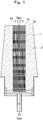
- the bottom blowing plug of the present example has a plug body 2 having an upper surface 2a which intersects with a gas blow-in direction (the direction of the arrow A1), and pipes 1 each having a through hole 1a regularly embedded in the plug body 2.
- the term "approximating" herein means not being exactly P mm but falling within a certain range.
- a group of openings constituted by all openings comprises a central opening of a pipe at a center, and 127 openings at vertices or on sides of six regular concentric hexagons.
- the opening group portion is a hexagonal portion formed by connecting centers of openings of six pipes A, B, C, D, E and F located at vertices of the outermost regular concentric hexagon H6 .
- Area S o cm 2 of this opening group portion is 135 cm 2 .
- the upper surface of this bottom blowing plug is a trapezoid having an upper base W1 mm of 250 mm in length, a lower base W2 mm of 350 mm in length, a height L mm of 300 mm in length.
- Area S u cm 2 of the upper surface is 900 cm 2 . Therefore, the area S o cm 2 of the opening group portion of the bottom blowing plug of the present example is 15 % of the area S u cm 2 of the upper surface, and distance from an opening on an outermost contour of the opening group portion to the periphery of the upper surface is long. Therefore, the bottom blowing plug of the present example has a good spalling resistance and thus has a good durability.
- the number of openings is 127 and the area S o cm 2 of the opening group portion is 135 cm 2 , density of the openings constituting the opening group portion is 0.94 opening/cm 2 .
- FIG. 3 A top view of a bottom blowing plug of a modification of Example 1 is shown in Fig. 3 .
- the bottom blowing plug of this modification is the same as that of Example 1, except that six pipes are removed from the pipes located at the vertices and on the sides of the outermost regular concentric hexagon of the bottom blowing plug of Example 1.
- the removed pipes are four pipes marked with the reference characters A, C, D and E in Fig. 2 , one pipe next to the pipe with the reference character C to the right and one pipe next to the pipe with the reference character E to the right, that is, six pipes in total.
- the bottom blowing plug of the present example is obtained by changing the shape of the upper surface 2a of the plug body 2 of the bottom blowing plug of Example 1 shown in Fig. 1 to a rectangle.
- the bottom blowing plug of the present example has an upper surface 2a which intersects with a gas blow- in direction, and pipes 1 each having a through hole 1a regularly embedded in a central portion of the plug body 2.
- a group of pipes comprises 100 pipes 1 and the pipes are located at four corners of squares with sides of 8 mm formed by 10 vertical lines and 10 horizontal lines at a pitch P of 8 mm.
- a center O of an upper surface 2a of the plug body 2 is located at a center of the group of pipes.
- P is 8 mm and an inner diameter of each of the pipes 1 is 2 mm.
- Area S o cm 2 of an opening group portion is 52 cm 2 .
- the upper surface 2a of the bottom blowing plug is a rectangle of 280 mm in length (W3) and 300 mm in width (W4) and has an area S u of 840 cm 2 . Therefore, the area S o cm 2 of the opening group portion of the bottom blowing plug of the present example is 6.2 % of the area S u cm 2 of the upper surface.
- Distance from a periphery of the upper surface to a closest opening located at a shortest distance from the periphery is 104 mm.
- the bottom blowing plug of the present example has a good spalling resistance and thus has a good durability.
- the group of openings of Example 1 has openings at the vertices and on the sides of regular concentric hexagons, while the group of openings of Example 2 has openings at the vertices and on the sides of squares.
- arrangement of the openings does not need to have strong regularity.
- the description of the present invention says that the group of openings is located at the central portion of the upper surface, the term "central" is not used in a strict meaning and the central portion can be a portion close to a center.
Landscapes
- Chemical & Material Sciences (AREA)
- Engineering & Computer Science (AREA)
- Materials Engineering (AREA)
- Metallurgy (AREA)
- Organic Chemistry (AREA)
- Manufacturing & Machinery (AREA)
- Carbon Steel Or Casting Steel Manufacturing (AREA)
- Treatment Of Steel In Its Molten State (AREA)
- Tires In General (AREA)
- Valve Housings (AREA)
Claims (4)
- Bodenblasstopfen, der an einem kombinierten Blaskonverter befestigbar ist, der 150 t oder mehr von geschmolzenem Eisen auf einmal verarbeiten kann, und einen Stopfenkörper umfasst, der eine obere Fläche zum Berühren des geschmolzenen Eisens hat, wobei die obere Fläche eine Gruppe von Öffnungen hat, die Öffnungen von mindestens 30 Durchgangslöchern aufweist, und wobei ein Inertgas bei 20 bis 60 Nl/min aus jeder einzelnen der Öffnungen eingespeist wird, wobei
die Gruppe von Öffnungen an einem Mittelabschnitt der oberen Fläche des Stopfenkörpers angeordnet ist, und wenn Su cm2 ein Flächeninhalt der oberen Fläche ist und So cm2 ein Flächeninhalt eines Öffnungsgruppenabschnitts ist, in dem die Gruppe von Öffnungen angeordnet ist, dann gilt So/Su ≤ 0,25 und Su cm2 ≥ 400 cm2, und
eine Dichte der die Gruppe von Öffnungen darstellenden Öffnungen, die durch die Anzahl von Öffnungen geteilt durch den Flächeninhalt So des Öffnungsgruppenabschnitts ausgedrückt wird, 0,6 bis 3,9 Öffnung/cm2 ist. - Bodenblasstopfen nach Anspruch 1, wobei ein Abstand P von benachbarten Öffnungen 6 bis 12 mm ist.
- Bodenblasstopfen nach Anspruch 1 oder 2, wobei eine relative Anordnung der Öffnungen, die die Gruppe von Öffnungen darstellen, eine solche ist, dass die Öffnungen in der oberen Fläche des Stopfenkörpers ausgebildet sind, um jeweils an Eckpunkten von gleichseitigen Dreiecken oder Quadraten mit Seiten von P mm angeordnet zu sein.
- Bodenblasstopfen nach Anspruch 1, 2 oder 3, wobei eine Entfernung von einem Rand der oberen Fläche zu einer nächsten derjenigen Öffnungen, die mit einer kürzesten Entfernung von dem Rand angeordnet sind, größer ist als eine Entfernung von der nächsten der Öffnungen zu einer Mittelöffnung, die an einer Mitte der Gruppe von Öffnungen angeordnet ist.
Applications Claiming Priority (1)
| Application Number | Priority Date | Filing Date | Title |
|---|---|---|---|
| PCT/JP2015/005096 WO2017060937A1 (ja) | 2015-10-07 | 2015-10-07 | 底吹きプラグ |
Publications (3)
| Publication Number | Publication Date |
|---|---|
| EP3231878A1 EP3231878A1 (de) | 2017-10-18 |
| EP3231878A4 EP3231878A4 (de) | 2018-05-09 |
| EP3231878B1 true EP3231878B1 (de) | 2018-12-26 |
Family
ID=58488149
Family Applications (1)
| Application Number | Title | Priority Date | Filing Date |
|---|---|---|---|
| EP15888078.1A Revoked EP3231878B1 (de) | 2015-10-07 | 2015-10-07 | Spülstein |
Country Status (5)
| Country | Link |
|---|---|
| EP (1) | EP3231878B1 (de) |
| KR (1) | KR101828140B1 (de) |
| CN (1) | CN107075596B (de) |
| BR (1) | BR112016022757B1 (de) |
| WO (1) | WO2017060937A1 (de) |
Cited By (1)
| Publication number | Priority date | Publication date | Assignee | Title |
|---|---|---|---|---|
| WO2025107046A1 (pt) * | 2023-11-24 | 2025-05-30 | Shinagawa Refratários Do Brasil Ltda | Ventaneira multiplugue e seu uso no tratamento de aço |
Families Citing this family (1)
| Publication number | Priority date | Publication date | Assignee | Title |
|---|---|---|---|---|
| WO2019012601A1 (ja) * | 2017-07-11 | 2019-01-17 | 東京窯業株式会社 | 炉体及び底吹きプラグ |
Citations (2)
| Publication number | Priority date | Publication date | Assignee | Title |
|---|---|---|---|---|
| KR200461650Y1 (ko) | 2011-03-14 | 2012-07-26 | 토쿄 요교 가부시키가이샤 | 가스 취입 플러그 |
| JP2012229487A (ja) | 2011-04-11 | 2012-11-22 | Jfe Steel Corp | 羽口ブロック |
Family Cites Families (8)
| Publication number | Priority date | Publication date | Assignee | Title |
|---|---|---|---|---|
| JPS61207505A (ja) | 1985-03-12 | 1986-09-13 | Nippon Kokan Kk <Nkk> | 溶融金属精練炉の底吹きノズル |
| JPS62214121A (ja) * | 1986-03-17 | 1987-09-19 | Nippon Kokan Kk <Nkk> | ガス吹込みプラグ |
| JPH0129233Y2 (de) * | 1986-11-10 | 1989-09-06 | ||
| JPH0639613B2 (ja) * | 1989-06-22 | 1994-05-25 | 日本鋼管株式会社 | 底吹き羽口 |
| JPH0931527A (ja) * | 1995-07-17 | 1997-02-04 | Tokyo Yogyo Co Ltd | ガス吹き込み用プラグ |
| JP4443732B2 (ja) * | 2000-06-20 | 2010-03-31 | 東京窯業株式会社 | 溶湯用吹込ポーラスプラグ |
| JP2007262471A (ja) * | 2006-03-28 | 2007-10-11 | Tokyo Yogyo Co Ltd | ガス吹き込みプラグ |
| CN203602649U (zh) * | 2013-11-29 | 2014-05-21 | 武汉钢铁(集团)公司 | 一种小型冶炼容器的底吹结构 |
-
2015
- 2015-10-07 EP EP15888078.1A patent/EP3231878B1/de not_active Revoked
- 2015-10-07 CN CN201580001518.XA patent/CN107075596B/zh active Active
- 2015-10-07 WO PCT/JP2015/005096 patent/WO2017060937A1/ja not_active Ceased
- 2015-10-07 BR BR112016022757-3A patent/BR112016022757B1/pt active IP Right Grant
- 2015-10-07 KR KR1020157033034A patent/KR101828140B1/ko active Active
Patent Citations (2)
| Publication number | Priority date | Publication date | Assignee | Title |
|---|---|---|---|---|
| KR200461650Y1 (ko) | 2011-03-14 | 2012-07-26 | 토쿄 요교 가부시키가이샤 | 가스 취입 플러그 |
| JP2012229487A (ja) | 2011-04-11 | 2012-11-22 | Jfe Steel Corp | 羽口ブロック |
Cited By (1)
| Publication number | Priority date | Publication date | Assignee | Title |
|---|---|---|---|---|
| WO2025107046A1 (pt) * | 2023-11-24 | 2025-05-30 | Shinagawa Refratários Do Brasil Ltda | Ventaneira multiplugue e seu uso no tratamento de aço |
Also Published As
| Publication number | Publication date |
|---|---|
| WO2017060937A1 (ja) | 2017-04-13 |
| KR20170085616A (ko) | 2017-07-25 |
| CN107075596A (zh) | 2017-08-18 |
| EP3231878A1 (de) | 2017-10-18 |
| CN107075596B (zh) | 2018-10-02 |
| BR112016022757B1 (pt) | 2021-12-14 |
| BR112016022757A2 (pt) | 2018-01-16 |
| EP3231878A4 (de) | 2018-05-09 |
| KR101828140B1 (ko) | 2018-02-09 |
Similar Documents
| Publication | Publication Date | Title |
|---|---|---|
| ES2901404T3 (es) | Almohadilla de impacto | |
| EP3231878A1 (de) | Bodenblasender stecker | |
| JP5553179B2 (ja) | 転炉脱炭精錬におけるスピッティング低減法 | |
| JP6037367B2 (ja) | 耐火性インパクトパッド | |
| CN103429764B (zh) | 可倾斜的氧气转炉 | |
| US20110186602A1 (en) | Vortex inhibitor | |
| KR200461650Y1 (ko) | 가스 취입 플러그 | |
| JP6245455B2 (ja) | 転炉の底吹き羽口ブロック | |
| NZ749779B2 (en) | Impact pad | |
| JPWO2019012601A1 (ja) | 炉体及び底吹きプラグ | |
| JPS61207505A (ja) | 溶融金属精練炉の底吹きノズル | |
| JP6332322B2 (ja) | 転炉の炉体 | |
| JP2018131675A (ja) | 脱炭用吹錬ランスチップ | |
| KR100860315B1 (ko) | 로에서 사용되는 노즐 회전형 톱랜스 | |
| KR102235235B1 (ko) | 제강 래들 | |
| CN216575499U (zh) | 一种用于钢水中间包的稳流装置 | |
| JP2715766B2 (ja) | ゴルフボール | |
| JP2005327480A (ja) | 架空ケーブル | |
| JP2007224398A (ja) | 精錬用容器で用いる底吹き羽口 | |
| JPH0724961U (ja) | 溶融金属攪拌用ランス | |
| JP2022160897A (ja) | 溶融金属容器のライニング構造 | |
| EP0195158A2 (de) | Zwischengefäss-Ausfluss-Vorrichtungen | |
| JPH01191732A (ja) | 精錬用容器における底吹き方法 | |
| JP2001152239A (ja) | ガス吹き込み用ランスパイプ | |
| KR20170026727A (ko) | 용강의 저취조업방법 |
Legal Events
| Date | Code | Title | Description |
|---|---|---|---|
| STAA | Information on the status of an ep patent application or granted ep patent |
Free format text: STATUS: UNKNOWN |
|
| STAA | Information on the status of an ep patent application or granted ep patent |
Free format text: STATUS: THE INTERNATIONAL PUBLICATION HAS BEEN MADE |
|
| PUAI | Public reference made under article 153(3) epc to a published international application that has entered the european phase |
Free format text: ORIGINAL CODE: 0009012 |
|
| STAA | Information on the status of an ep patent application or granted ep patent |
Free format text: STATUS: REQUEST FOR EXAMINATION WAS MADE |
|
| 17P | Request for examination filed |
Effective date: 20161013 |
|
| AK | Designated contracting states |
Kind code of ref document: A1 Designated state(s): AL AT BE BG CH CY CZ DE DK EE ES FI FR GB GR HR HU IE IS IT LI LT LU LV MC MK MT NL NO PL PT RO RS SE SI SK SM TR |
|
| AX | Request for extension of the european patent |
Extension state: BA ME |
|
| R17P | Request for examination filed (corrected) |
Effective date: 20161013 |
|
| A4 | Supplementary search report drawn up and despatched |
Effective date: 20180409 |
|
| RIC1 | Information provided on ipc code assigned before grant |
Ipc: C21C 5/34 20060101ALI20180403BHEP Ipc: C21C 7/00 20060101AFI20180403BHEP Ipc: C21C 7/072 20060101ALI20180403BHEP Ipc: C21C 5/48 20060101ALI20180403BHEP |
|
| GRAP | Despatch of communication of intention to grant a patent |
Free format text: ORIGINAL CODE: EPIDOSNIGR1 |
|
| STAA | Information on the status of an ep patent application or granted ep patent |
Free format text: STATUS: GRANT OF PATENT IS INTENDED |
|
| RIC1 | Information provided on ipc code assigned before grant |
Ipc: C21C 5/48 20060101ALI20180606BHEP Ipc: C21C 5/34 20060101ALI20180606BHEP Ipc: C21C 7/00 20060101AFI20180606BHEP Ipc: C21C 7/072 20060101ALI20180606BHEP |
|
| INTG | Intention to grant announced |
Effective date: 20180709 |
|
| GRAS | Grant fee paid |
Free format text: ORIGINAL CODE: EPIDOSNIGR3 |
|
| GRAA | (expected) grant |
Free format text: ORIGINAL CODE: 0009210 |
|
| STAA | Information on the status of an ep patent application or granted ep patent |
Free format text: STATUS: THE PATENT HAS BEEN GRANTED |
|
| AK | Designated contracting states |
Kind code of ref document: B1 Designated state(s): AL AT BE BG CH CY CZ DE DK EE ES FI FR GB GR HR HU IE IS IT LI LT LU LV MC MK MT NL NO PL PT RO RS SE SI SK SM TR |
|
| DAV | Request for validation of the european patent (deleted) | ||
| DAX | Request for extension of the european patent (deleted) | ||
| REG | Reference to a national code |
Ref country code: GB Ref legal event code: FG4D |
|
| REG | Reference to a national code |
Ref country code: CH Ref legal event code: EP |
|
| REG | Reference to a national code |
Ref country code: AT Ref legal event code: REF Ref document number: 1081508 Country of ref document: AT Kind code of ref document: T Effective date: 20190115 |
|
| REG | Reference to a national code |
Ref country code: DE Ref legal event code: R096 Ref document number: 602015022554 Country of ref document: DE |
|
| REG | Reference to a national code |
Ref country code: IE Ref legal event code: FG4D |
|
| PG25 | Lapsed in a contracting state [announced via postgrant information from national office to epo] |
Ref country code: NO Free format text: LAPSE BECAUSE OF FAILURE TO SUBMIT A TRANSLATION OF THE DESCRIPTION OR TO PAY THE FEE WITHIN THE PRESCRIBED TIME-LIMIT Effective date: 20190326 Ref country code: LT Free format text: LAPSE BECAUSE OF FAILURE TO SUBMIT A TRANSLATION OF THE DESCRIPTION OR TO PAY THE FEE WITHIN THE PRESCRIBED TIME-LIMIT Effective date: 20181226 Ref country code: LV Free format text: LAPSE BECAUSE OF FAILURE TO SUBMIT A TRANSLATION OF THE DESCRIPTION OR TO PAY THE FEE WITHIN THE PRESCRIBED TIME-LIMIT Effective date: 20181226 Ref country code: HR Free format text: LAPSE BECAUSE OF FAILURE TO SUBMIT A TRANSLATION OF THE DESCRIPTION OR TO PAY THE FEE WITHIN THE PRESCRIBED TIME-LIMIT Effective date: 20181226 Ref country code: BG Free format text: LAPSE BECAUSE OF FAILURE TO SUBMIT A TRANSLATION OF THE DESCRIPTION OR TO PAY THE FEE WITHIN THE PRESCRIBED TIME-LIMIT Effective date: 20190326 |
|
| REG | Reference to a national code |
Ref country code: NL Ref legal event code: MP Effective date: 20181226 |
|
| REG | Reference to a national code |
Ref country code: LT Ref legal event code: MG4D |
|
| PG25 | Lapsed in a contracting state [announced via postgrant information from national office to epo] |
Ref country code: SE Free format text: LAPSE BECAUSE OF FAILURE TO SUBMIT A TRANSLATION OF THE DESCRIPTION OR TO PAY THE FEE WITHIN THE PRESCRIBED TIME-LIMIT Effective date: 20181226 Ref country code: RS Free format text: LAPSE BECAUSE OF FAILURE TO SUBMIT A TRANSLATION OF THE DESCRIPTION OR TO PAY THE FEE WITHIN THE PRESCRIBED TIME-LIMIT Effective date: 20181226 Ref country code: GR Free format text: LAPSE BECAUSE OF FAILURE TO SUBMIT A TRANSLATION OF THE DESCRIPTION OR TO PAY THE FEE WITHIN THE PRESCRIBED TIME-LIMIT Effective date: 20190327 Ref country code: AL Free format text: LAPSE BECAUSE OF FAILURE TO SUBMIT A TRANSLATION OF THE DESCRIPTION OR TO PAY THE FEE WITHIN THE PRESCRIBED TIME-LIMIT Effective date: 20181226 |
|
| REG | Reference to a national code |
Ref country code: AT Ref legal event code: MK05 Ref document number: 1081508 Country of ref document: AT Kind code of ref document: T Effective date: 20181226 |
|
| PG25 | Lapsed in a contracting state [announced via postgrant information from national office to epo] |
Ref country code: NL Free format text: LAPSE BECAUSE OF FAILURE TO SUBMIT A TRANSLATION OF THE DESCRIPTION OR TO PAY THE FEE WITHIN THE PRESCRIBED TIME-LIMIT Effective date: 20181226 |
|
| PG25 | Lapsed in a contracting state [announced via postgrant information from national office to epo] |
Ref country code: PL Free format text: LAPSE BECAUSE OF FAILURE TO SUBMIT A TRANSLATION OF THE DESCRIPTION OR TO PAY THE FEE WITHIN THE PRESCRIBED TIME-LIMIT Effective date: 20181226 Ref country code: ES Free format text: LAPSE BECAUSE OF FAILURE TO SUBMIT A TRANSLATION OF THE DESCRIPTION OR TO PAY THE FEE WITHIN THE PRESCRIBED TIME-LIMIT Effective date: 20181226 Ref country code: PT Free format text: LAPSE BECAUSE OF FAILURE TO SUBMIT A TRANSLATION OF THE DESCRIPTION OR TO PAY THE FEE WITHIN THE PRESCRIBED TIME-LIMIT Effective date: 20190426 Ref country code: IT Free format text: LAPSE BECAUSE OF FAILURE TO SUBMIT A TRANSLATION OF THE DESCRIPTION OR TO PAY THE FEE WITHIN THE PRESCRIBED TIME-LIMIT Effective date: 20181226 Ref country code: CZ Free format text: LAPSE BECAUSE OF FAILURE TO SUBMIT A TRANSLATION OF THE DESCRIPTION OR TO PAY THE FEE WITHIN THE PRESCRIBED TIME-LIMIT Effective date: 20181226 |
|
| PG25 | Lapsed in a contracting state [announced via postgrant information from national office to epo] |
Ref country code: IS Free format text: LAPSE BECAUSE OF FAILURE TO SUBMIT A TRANSLATION OF THE DESCRIPTION OR TO PAY THE FEE WITHIN THE PRESCRIBED TIME-LIMIT Effective date: 20190426 Ref country code: RO Free format text: LAPSE BECAUSE OF FAILURE TO SUBMIT A TRANSLATION OF THE DESCRIPTION OR TO PAY THE FEE WITHIN THE PRESCRIBED TIME-LIMIT Effective date: 20181226 Ref country code: EE Free format text: LAPSE BECAUSE OF FAILURE TO SUBMIT A TRANSLATION OF THE DESCRIPTION OR TO PAY THE FEE WITHIN THE PRESCRIBED TIME-LIMIT Effective date: 20181226 Ref country code: SM Free format text: LAPSE BECAUSE OF FAILURE TO SUBMIT A TRANSLATION OF THE DESCRIPTION OR TO PAY THE FEE WITHIN THE PRESCRIBED TIME-LIMIT Effective date: 20181226 Ref country code: SK Free format text: LAPSE BECAUSE OF FAILURE TO SUBMIT A TRANSLATION OF THE DESCRIPTION OR TO PAY THE FEE WITHIN THE PRESCRIBED TIME-LIMIT Effective date: 20181226 |
|
| REG | Reference to a national code |
Ref country code: DE Ref legal event code: R026 Ref document number: 602015022554 Country of ref document: DE |
|
| PLBI | Opposition filed |
Free format text: ORIGINAL CODE: 0009260 |
|
| PLAX | Notice of opposition and request to file observation + time limit sent |
Free format text: ORIGINAL CODE: EPIDOSNOBS2 |
|
| PG25 | Lapsed in a contracting state [announced via postgrant information from national office to epo] |
Ref country code: DK Free format text: LAPSE BECAUSE OF FAILURE TO SUBMIT A TRANSLATION OF THE DESCRIPTION OR TO PAY THE FEE WITHIN THE PRESCRIBED TIME-LIMIT Effective date: 20181226 Ref country code: AT Free format text: LAPSE BECAUSE OF FAILURE TO SUBMIT A TRANSLATION OF THE DESCRIPTION OR TO PAY THE FEE WITHIN THE PRESCRIBED TIME-LIMIT Effective date: 20181226 |
|
| 26 | Opposition filed |
Opponent name: REFRACTORY INTELLECTUAL PROPERTY GMBH & CO. KG Effective date: 20190924 |
|
| PLBB | Reply of patent proprietor to notice(s) of opposition received |
Free format text: ORIGINAL CODE: EPIDOSNOBS3 |
|
| PG25 | Lapsed in a contracting state [announced via postgrant information from national office to epo] |
Ref country code: SI Free format text: LAPSE BECAUSE OF FAILURE TO SUBMIT A TRANSLATION OF THE DESCRIPTION OR TO PAY THE FEE WITHIN THE PRESCRIBED TIME-LIMIT Effective date: 20181226 |
|
| PG25 | Lapsed in a contracting state [announced via postgrant information from national office to epo] |
Ref country code: TR Free format text: LAPSE BECAUSE OF FAILURE TO SUBMIT A TRANSLATION OF THE DESCRIPTION OR TO PAY THE FEE WITHIN THE PRESCRIBED TIME-LIMIT Effective date: 20181226 |
|
| REG | Reference to a national code |
Ref country code: DE Ref legal event code: R119 Ref document number: 602015022554 Country of ref document: DE |
|
| PG25 | Lapsed in a contracting state [announced via postgrant information from national office to epo] |
Ref country code: MC Free format text: LAPSE BECAUSE OF FAILURE TO SUBMIT A TRANSLATION OF THE DESCRIPTION OR TO PAY THE FEE WITHIN THE PRESCRIBED TIME-LIMIT Effective date: 20181226 |
|
| REG | Reference to a national code |
Ref country code: CH Ref legal event code: PL |
|
| PG25 | Lapsed in a contracting state [announced via postgrant information from national office to epo] |
Ref country code: LU Free format text: LAPSE BECAUSE OF NON-PAYMENT OF DUE FEES Effective date: 20191007 Ref country code: DE Free format text: LAPSE BECAUSE OF NON-PAYMENT OF DUE FEES Effective date: 20200501 Ref country code: CH Free format text: LAPSE BECAUSE OF NON-PAYMENT OF DUE FEES Effective date: 20191031 Ref country code: LI Free format text: LAPSE BECAUSE OF NON-PAYMENT OF DUE FEES Effective date: 20191031 |
|
| GBPC | Gb: european patent ceased through non-payment of renewal fee |
Effective date: 20191007 |
|
| PG25 | Lapsed in a contracting state [announced via postgrant information from national office to epo] |
Ref country code: IE Free format text: LAPSE BECAUSE OF NON-PAYMENT OF DUE FEES Effective date: 20191007 Ref country code: GB Free format text: LAPSE BECAUSE OF NON-PAYMENT OF DUE FEES Effective date: 20191007 |
|
| PG25 | Lapsed in a contracting state [announced via postgrant information from national office to epo] |
Ref country code: CY Free format text: LAPSE BECAUSE OF FAILURE TO SUBMIT A TRANSLATION OF THE DESCRIPTION OR TO PAY THE FEE WITHIN THE PRESCRIBED TIME-LIMIT Effective date: 20181226 |
|
| APAH | Appeal reference modified |
Free format text: ORIGINAL CODE: EPIDOSCREFNO |
|
| APBM | Appeal reference recorded |
Free format text: ORIGINAL CODE: EPIDOSNREFNO |
|
| APBP | Date of receipt of notice of appeal recorded |
Free format text: ORIGINAL CODE: EPIDOSNNOA2O |
|
| APAW | Appeal reference deleted |
Free format text: ORIGINAL CODE: EPIDOSDREFNO |
|
| APBM | Appeal reference recorded |
Free format text: ORIGINAL CODE: EPIDOSNREFNO |
|
| APBP | Date of receipt of notice of appeal recorded |
Free format text: ORIGINAL CODE: EPIDOSNNOA2O |
|
| PG25 | Lapsed in a contracting state [announced via postgrant information from national office to epo] |
Ref country code: MT Free format text: LAPSE BECAUSE OF FAILURE TO SUBMIT A TRANSLATION OF THE DESCRIPTION OR TO PAY THE FEE WITHIN THE PRESCRIBED TIME-LIMIT Effective date: 20181226 Ref country code: HU Free format text: LAPSE BECAUSE OF FAILURE TO SUBMIT A TRANSLATION OF THE DESCRIPTION OR TO PAY THE FEE WITHIN THE PRESCRIBED TIME-LIMIT; INVALID AB INITIO Effective date: 20151007 |
|
| APBQ | Date of receipt of statement of grounds of appeal recorded |
Free format text: ORIGINAL CODE: EPIDOSNNOA3O |
|
| PG25 | Lapsed in a contracting state [announced via postgrant information from national office to epo] |
Ref country code: MK Free format text: LAPSE BECAUSE OF FAILURE TO SUBMIT A TRANSLATION OF THE DESCRIPTION OR TO PAY THE FEE WITHIN THE PRESCRIBED TIME-LIMIT Effective date: 20181226 |
|
| REG | Reference to a national code |
Ref country code: DE Ref legal event code: R103 Ref document number: 602015022554 Country of ref document: DE Ref country code: DE Ref legal event code: R064 Ref document number: 602015022554 Country of ref document: DE |
|
| APBU | Appeal procedure closed |
Free format text: ORIGINAL CODE: EPIDOSNNOA9O |
|
| RDAF | Communication despatched that patent is revoked |
Free format text: ORIGINAL CODE: EPIDOSNREV1 |
|
| STAA | Information on the status of an ep patent application or granted ep patent |
Free format text: STATUS: PATENT REVOKED |
|
| PGFP | Annual fee paid to national office [announced via postgrant information from national office to epo] |
Ref country code: FR Payment date: 20231026 Year of fee payment: 9 Ref country code: FI Payment date: 20231020 Year of fee payment: 9 |
|
| RDAG | Patent revoked |
Free format text: ORIGINAL CODE: 0009271 |
|
| REG | Reference to a national code |
Ref country code: CH Ref legal event code: PL |
|
| PGFP | Annual fee paid to national office [announced via postgrant information from national office to epo] |
Ref country code: BE Payment date: 20231019 Year of fee payment: 9 |
|
| 27W | Patent revoked |
Effective date: 20231023 |