EP3228779B1 - Hook for moving formwork elements - Google Patents
Hook for moving formwork elements Download PDFInfo
- Publication number
- EP3228779B1 EP3228779B1 EP17159376.7A EP17159376A EP3228779B1 EP 3228779 B1 EP3228779 B1 EP 3228779B1 EP 17159376 A EP17159376 A EP 17159376A EP 3228779 B1 EP3228779 B1 EP 3228779B1
- Authority
- EP
- European Patent Office
- Prior art keywords
- pawl
- retaining latch
- hook
- housing
- infeed mouth
- Prior art date
- Legal status (The legal status is an assumption and is not a legal conclusion. Google has not performed a legal analysis and makes no representation as to the accuracy of the status listed.)
- Not-in-force
Links
- 238000009415 formwork Methods 0.000 title claims description 31
- 230000000903 blocking effect Effects 0.000 claims description 21
- XEEYBQQBJWHFJM-UHFFFAOYSA-N Iron Chemical compound [Fe] XEEYBQQBJWHFJM-UHFFFAOYSA-N 0.000 description 8
- 230000008901 benefit Effects 0.000 description 4
- 229910052742 iron Inorganic materials 0.000 description 4
- 230000003287 optical effect Effects 0.000 description 4
- 239000003086 colorant Substances 0.000 description 2
- 238000010276 construction Methods 0.000 description 2
- 241001527806 Iti Species 0.000 description 1
- 238000004873 anchoring Methods 0.000 description 1
- 230000001419 dependent effect Effects 0.000 description 1
- 231100001261 hazardous Toxicity 0.000 description 1
- 238000004519 manufacturing process Methods 0.000 description 1
- 239000000203 mixture Substances 0.000 description 1
Images

Classifications
-
- E—FIXED CONSTRUCTIONS
- E04—BUILDING
- E04G—SCAFFOLDING; FORMS; SHUTTERING; BUILDING IMPLEMENTS OR AIDS, OR THEIR USE; HANDLING BUILDING MATERIALS ON THE SITE; REPAIRING, BREAKING-UP OR OTHER WORK ON EXISTING BUILDINGS
- E04G19/00—Auxiliary treatment of forms, e.g. dismantling; Cleaning devices
- E04G19/003—Arrangements for stabilising the forms or for moving the forms from one place to another
-
- B—PERFORMING OPERATIONS; TRANSPORTING
- B66—HOISTING; LIFTING; HAULING
- B66C—CRANES; LOAD-ENGAGING ELEMENTS OR DEVICES FOR CRANES, CAPSTANS, WINCHES, OR TACKLES
- B66C1/00—Load-engaging elements or devices attached to lifting or lowering gear of cranes or adapted for connection therewith for transmitting lifting forces to articles or groups of articles
- B66C1/10—Load-engaging elements or devices attached to lifting or lowering gear of cranes or adapted for connection therewith for transmitting lifting forces to articles or groups of articles by mechanical means
- B66C1/22—Rigid members, e.g. L-shaped members, with parts engaging the under surface of the loads; Crane hooks
- B66C1/24—Single members engaging the loads from one side only
-
- B—PERFORMING OPERATIONS; TRANSPORTING
- B66—HOISTING; LIFTING; HAULING
- B66C—CRANES; LOAD-ENGAGING ELEMENTS OR DEVICES FOR CRANES, CAPSTANS, WINCHES, OR TACKLES
- B66C1/00—Load-engaging elements or devices attached to lifting or lowering gear of cranes or adapted for connection therewith for transmitting lifting forces to articles or groups of articles
- B66C1/10—Load-engaging elements or devices attached to lifting or lowering gear of cranes or adapted for connection therewith for transmitting lifting forces to articles or groups of articles by mechanical means
- B66C1/42—Gripping members engaging only the external or internal surfaces of the articles
- B66C1/44—Gripping members engaging only the external or internal surfaces of the articles and applying frictional forces
- B66C1/48—Gripping members engaging only the external or internal surfaces of the articles and applying frictional forces to vertical edge portions of sheets, tubes, or like thin or thin-walled articles
Definitions
- the invention concerns a hook for moving formwork elements with an infeed mouth for receiving a frame profile of concrete formwork elements.
- the hook comprises a rotatably mounted retaining latch.
- the retaining latch can be moved back and forth between a closing position and a receiving position. In the closing position, a frame profile, which is received by the infeed mouth and thereby hold, cannot leave the infeed mouth of the hook anymore. In the receiving position, a received frame profile can leave the infeed mouth and the hook can thereby be detached from the formwork.
- the hook comprises an attachment means in order to attach the retaining latch for example with a chain to a crane.
- the retaining latch can be moved from the receiving position to the closing position by means of loading the attachment means.
- Hooks of the above mentioned kind are known from the documents DE 31 11 634 A1 as well as WO 2010/124666 A1 .
- Formwork elements are known from the document WO 2014/012681 A1 .
- Such formwork elements are used in conjunction with anchoring systems comprising anchor rods for example for the production of concrete walls.
- Formwork element comprise on the front side a formwork facing and on the back side frame profiles for supporting the formwork facing.
- Such formwork elements are set up for example by means of a crane, disassembled after the curing of the concrete and subsequently moved on demand.
- the hook of such kind as mentioned at the beginning serves the attachment of a formwork element to a crane or to another set-up and/or transport device for setting up, disassembling and/or moving.
- ES 2265211 A1 discloses a hook for moving formwork elements according to the preamble of claim 1.
- a hook for moving formwork elements comprises an infeed mouth (infeed orifice) for receiving a frame profile of concrete formwork elements.
- a retaining latch which can be moved back and forth between a closing position and a receiving position. By moving the retaining latch from the receiving position to the closing position, an infeed section of the infeed mouth is constricted for holding a frame profile. Thereby, the frame profile being received in the infeed mouth cannot leave the infeed mouth anymore.
- the retaining latch can for example be connected to a chain of a crane.
- the attachment means comprises in a preferred embodiment a chain.
- the retaining latch is moved from the receiving position to the closing position by means of loading (applying a load to) the infeed mouth and a therewith accompanying load on the attachment means.
- the preferably provided chain of the hook can be grasped manually in order induce by hand a sufficient strong pull in the retaining latch, which brings the retaining latch to the closing position.
- the infeed mouth is loaded, when the infeed mouth supports a load like a formwork element.
- the retaining latch cannot leave its closing position when the pawl blocks the retaining latch.
- the retaining latch can thus not leave its closing position for two different reasons when a load is supported (born) by the hook. Firstly, supporting of the load prevents that the retaining latch can leave its closing position unintentionally (not as intended). At the same time, this is prevented by the pawl. Although providing a pawl does not appear necessary at first view and thus wasted, because already supporting the load prevents that the retaining latch can leave its closing position unintentionally. However, a problem may arise when the load, like usually a formwork element, is put on the ground. Then, the supporting of the load is omitted at least for short time, which holds the retaining latch in its closing position.
- the force, which has to be spent to bring the retaining latch from the receiving position to the closing position, is preferably adjusted in a way that at least the own weight (tare weight) of the hook has to be overcome.
- the hook can be hanged up for example to a crane without immediately taking the closing position. Thereby, hooking in of a load is particularly easy.
- the pawl comprises a first end, which reaches out of a housing of the hook when the pawl is located in its blocking position.
- the end does not reach out of the housing of the hook when the pawl is located in a releasing position, in which the retaining latch is not blocked by the pawl.
- an optical aid is provided, which indicates the position of the pawl in a way that it is clearly recognizable from outside.
- this end is therefore colored, namely particularly green.
- the before mentioned first end reaches sidewards out of the housing when the pawl is located in its blocking position.
- This end may in particular be used to move the pawl from its blocking position to its releasing position by grasping the end.
- the sidewards arrangement is particularly suitable and comfortable for such manual operation.
- Sidewards refers to a sideward wall of the housing when the hook is attached and arranged as intended (according to predefined normal operation) for supporting a load, thus for example attached to a lower end of a chain of a crane.
- the pawl comprises a second end, which reaches out of a housing of the hook when the pawl is located in a releasing position, in which the retaining latch is not blocked by the pawl.
- the end does not reach out of the housing of the hook when the pawl is located in its blocking position.
- An optical aid is thereby made available, which indicates the position of the pawl in a way that it is clearly recognizable from outside.
- this end is therefore colored, namely particularly red. When the particularly red end reaches out of the housing and is thus visible also from a greater distance, it is thereby indicated that the retaining latch is not blocked by the pawl and there is thus a risk of accident arising from the load, which is received by the hook.
- the before mentioned particularly red colored second end reaches out of the housing preferably downwards when the pawl is located in its releasing position.
- the downwards reaching out is of particular advantage, because a reaching out of this end is visible from any location. Because the view of a reaching out end cannot be blocked by a housing wall when the hook is attached as intended for example to the chain of a crane.
- Downwards reaching out of a housing refers to a lower wall of the housing when the hook is attached and arranged as intended for supporting a load, thus for example attached to a lower end of a chain of a crane. This lower wall is then visible to persons, which are located below the hook.
- both a red colored end of the pawl and also a green colored end of the pawl are both a red colored end of the pawl and also a green colored end of the pawl.
- green colored end When the green colored end reaches out of the housing, then it is indicated that everything is fine.
- red colored end of the pawl reaches out then the receiving position is indicated or a not intended latching respectively blockage by the pawl.
- green and red also other colors may be provided.
- Green and red are however preferred for the reason that these are typical signal colors, which stands for "everything is fine" or “caution” respectively "hazardous".
- a housing opening specifically at the bottom side of the housing wall, through which an anchor rod or a flat iron can be pushed through in such a way that the pawl can be moved from its blocking position to its releasing position, when the hook is as intended attached for example to a chain to a crane.
- anchor rods No special tool is needed.
- the opening is used to apply the hook in greater height to a load, thus in particular to a formwork respectively formwork element.
- an end of a common construction zone means such as for example an end of an anchor rod is inserted in the opening.
- the other end of the common construction zone means is manually moved in a suitable way in order to thereby move the hook suitably to the load or to suitably hold.
- the opening thus can be of double benefit as it also enables a remote release respectively a remote operation in the described manner.
- the housing of the hook can be supported against the retaining latch, when the retaining latch is located in its closing position.
- the housing comprises the infeed mouth. Punctual overloads are thereby avoided when a load is supported by means of the infeed mouth.
- the support means are preferably arranged around the infeed mouth in order to further improve avoiding punctual overloads.
- the support means comprise: a pin for pivotable mounting the retaining latch wherein the pin is mounted by means of the housing and/or a pin protruding from the retaining latch on which a lower wall of the infeed mouth can be supported and/or at least one oblong hole in a housing wall which can be supported against a protruding pin.
- the infeed mouth is formed at the upper side and at the bottom side by plane and/or parallel running walls.
- Upper side refers to the upper side of the infeed mouth when the hook is attached as intended for example to a chain of a crane.
- Bottom side refers to the lower side of the infeed mouth when the hook is attached as intended for example to a chain of a crane.
- the lower wall of the infeed mouth known from the WO 2010/124666 A1 which runs substantially horizontally in an attached condition of the hook, comprises a nose at the free end. This wall is thus not plane within the meaning of the present invention.
- the infeed mouth is thus not formed by a plane lower wall within the meaning of the present invention.
- the upper wall known from the WO 2010/124666 A1 runs plane but not parallel to the lower wall.
- the infeed mouth known from the document is thus not formed by two plane-parallel walls within the meaning of the present invention.
- the plane composition of the lower wall of the infeed mouth facilitates ease of moving a frame profile into the infeed mouth and also out of it especially compared to the lower wall known from the document WO 2010/124666 A1 .
- the upper wall is plane in order to not hamper the handling. Having both the lower wall and also the upper wall running in parallel to each other makes it possible to allow receiving and holding a plurality of different dimensioned frame profiles.
- the solution known from WO 2010/124666 A1 requires compared to that a sufficiently precisely adapted frame profile in order to allow receiving and holding it.
- a stud is moved into the infeed mouth for the constriction of a section of the infeed mouth when the retaining latch is moved in its closing position.
- the stud is moved through the lower wall of the infeed mouth into the infeed mouth.
- a frame profile which is arranged in the infeed mouth, can leave the infeed mouth. This is achieved particularly reliable when the stud is moved thought the lower wall into the infeed mouth.
- the pawl is advantageously by a spring biased towards blocking position.
- the safety is advantageously further increased as the pawl is supported by the spring reliably moved to its blocking position as soon as the retaining latch is located in its closing position.
- the retaining spring is advantageously biased by a spring towards receiving position.
- it is achieved that the retaining latch is moved as intended to its opened position when being released as intended, thus no load being supported any more and the blocking lever (pawl) was moved in its releasing position. This is especially of advantage when the retaining latch is not reachable from the ground but a hook should already be detached from a load.
- the invention furthermore concerns a system comprising a hook and at least two formwork elements with different dimensioned frame profiles, wherein both frame profiles can be received by the infeed mouth (2) and hold therein.
- a system comprising a hook and at least two formwork elements with different dimensioned frame profiles, wherein both frame profiles can be received by the infeed mouth (2) and hold therein.
- the infeed mouth with two plane-parallel lower and upper walls of the infeed mouth makes it possible to allow receiving and holding different frame profiles.
- the Figure 1 shows in a sectional view a hook 1 for moving formwork elements with an infeed mouth 2 for receiving a frame profile of formwork elements.
- the hook 1 comprises a retaining latch 3, which is rotatably mounted by means of pin 4. These are two pins, which are connected at opposing sidewalls of the housing and which mount a bearing shell for leg springs.
- the retaining latch 3 can be rotated back and forth between a closing position and a receiving position. In the closing position as shown in Figure 1 a stud 5 of the retaining latch 3 that is connected to an arm is reaching though a lower wall 20 into the infeed mouth 2 and thereby constricts an infeed section of the infeed mouth 2.
- a frame profile that is provided for that, which was brought in the infeed mouth 2, can then not leave the infeed mouth 2 of the hook 1 any more due to the constriction. This is prevented by the stud 5 when the stud 5 as shown in Figure 1 reaches through an opening in the lower housing wall 20 into the infeed mouth 2.
- the retaining latch 3 comprises an attachment means 6 at an end of a second arm in form of a grommet, which can be connected to a chain 14 of a crane.
- the retaining latch 3 is loaded.
- a torque rotation of force
- the hook 1 comprises a pawl 7 with two sidewalls, which are pivotable mounted by means of a pin 8.
- a pawl 7 with two sidewalls, which are pivotable mounted by means of a pin 8.
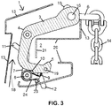
- the front sidewall of the pawl 7 is shown and in the Figure 3 the back sidewall.
- the pawl 7 being formed by two sidewalls is biased by means of a spring 24 (see Figure 3 ) in direction of closing position. Due to the bias, a torque is induced in the pawl 7, so that the pawl 7 can be moved from its released position, thus its releasing position, to its closing position, specifically in the case of Figure 1 counterclockwise about the pin 8.
- the closing position is shown in the Figure 1 .
- the hook 1 is closed.
- a pin 9 protruding from an arm of the pawl 7 is then located in a bulge 10 of the retaining latch 3, whereby it is prevented that the retaining latch 3 can be rotated from its closing position to the receiving position about the pin 4.
- the pawl 7 has two arms with a green colored first end 11 and a red colored second end 12.
- the end of the one arm 11 as well as the end of the other arm 12 are thus marked differently.
- the green colored end 11 of the one arm reaches sidewards out of the housing 13 of the hook 1 when the hook is attached as intended to a chain 14 of a crane as shown.
- the other red colored end 12 of the other arm then does not reach out of the housing 13.
- the red colored end 12 reaches (as shown in the Figure 3 ) downwards out of the housing 13.
- the green colored end 11 then does not reach out of the housing 13.
- the green colored end When the green colored end reaches out of the housing 13, then it can be based on it optically recognized also from greater distance that the retaining latch 3 is located in its closing position and the pawl 7 blocks the retaining latch such that the retaining latch 3 cannot leave its closing position. When the pawl 7 is located in its released position, the retaining latch 3 is not blocked. This can also be recognized from greater distant and especially also from the ground by means of the red colored end 12, which then reaches downwards out of the housing 13. This end cannot be covered by the housing 13.
- the green colored end 11 can then be manually grasped and swiveled. Thereby, the pawl 7 can be moved from its blocking position to its released position. Subsequent to that, the retaining latch 3 can be rotated to its receiving position.
- the housing opening 17 enables a remote operation respectively remote release by means of an anchor rod, a lath or the like.
- the opening 17 is adjacent to the back wall of the hook 1 and thus arranged at a sufficiently protected location such that also for this reason an unintentionally release can be avoided.
- the back side is the side, which faces the infeed mouth (lies opposite to it).
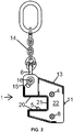
- Two opposing sidewalls of the hook housing 13 comprises each an oblong hole 15. An end of a pin 16 reaches into each oblong hole 15. The pin 16 leads though the retaining latch 3 and is arranged neighboring to the attachment means 6.
- the oblong hole 15 limits the rotational movement of the retaining latch 3.
- the pin 16 abuts against the other end of the oblong hole 15, whereby the rotation is limited in the other direction.
- a pin 23 is connected to the two opposing sides of the housing 13, which serves as stop for the red colored end 12. By means of the pin 23, the swiveling of the pawl 7 can thus be limited towards releasing position. Alternatively or additionally, this pin 23 serves the holding of a leg of the biased spring, which allows moving the pawl 7 into the blocking position by means of spring force.
- a protruding pin 19 is mounted at the arm with the stud 5 of the retaining latch 3.
- the pin 19 supports (leans) against the housing 13 when the retaining latch 3 was moved to its closing position.
- the pin 19 thereby contributes to limiting the rotational movement of the retaining latch 3 towards closing position.
- the infeed mouth 2 is formed by two plane-parallel walls 20 from above and below.
- the base of the infeed mouth 2 is bordered by a wall 21.
- the bulge 10 supports (leans) on the axis 8 of the pawl 7. This supporting (leaning) limits on the one hand the rotation of the retaining latch 3 beyond its receiving position.
- the retaining latch 3 is furthermore biased by a not shown spring towards opening position.
- the housing 13 supports on several points on the retaining latch, whereby punctual overloads of the housing 13 are avoided and whereby the housing becomes particularly stable.
- a first support is carried out by the oblong hole 15, which abuts with one end on the pin 16 of the retaining latch 16 during supporting (carrying) a load, wherein the load is then hold in the infeed mouth 2.
- a second support is carried out by the pin 4, which is mounted by means of the sidewalls 22 of the housing 13 as can be seen from Figure 2 .
- three different supports are arranged around the infeed mouth in order to avoid punctual overloads.
- the housing walls 13, 20, 21 and 22 are welded together. Thereby, in conjunction with the before mentioned support measures, such a stable housing is obtained that the hook 1 - as tests have shown - allows free falling from 3 meters height on a ground made of concrete without losing its functional ities.
- a hook for moving formwork elements is thus made available, which functions in a very reliable manner, which can be handled simply and manifold manners, and which is sufficiently secured in such a way that accident risks are minimized.
- the both sidewalls of the pawl 7 are connected to each other by a plurality of pins 16 and 19. As these pins are provided for other reasons as already described, these pins 16 and 19 cover several functions, which keeps the number of parts low.
- the Figure 2 shows a side view of the hook 1 on the sidewalls 22 of the housing 13.
- the oblong holes 15 allows a rotation of the retaining latch 3 relatively to the housing 13, 22 and thus relatively to the infeed mouth 2, which is formed by the housing walls 20, 21.
- the Figure 3 shows the hook 1 in the opened position, specifically compared to Figure 1 with a changed plane of the sectional view.
- the back sidewall of the pawl 7 is shown. Both sidewalls of the pawl are arranged towards both sides of the retaining latch 3.
Landscapes
- Engineering & Computer Science (AREA)
- Mechanical Engineering (AREA)
- Architecture (AREA)
- Civil Engineering (AREA)
- Structural Engineering (AREA)
- Load-Engaging Elements For Cranes (AREA)
- Hooks, Suction Cups, And Attachment By Adhesive Means (AREA)
Priority Applications (1)
| Application Number | Priority Date | Filing Date | Title |
|---|---|---|---|
| PL17159376T PL3228779T3 (pl) | 2016-04-07 | 2017-03-06 | Hak do przemieszczania elementów szalunku |
Applications Claiming Priority (1)
| Application Number | Priority Date | Filing Date | Title |
|---|---|---|---|
| DE102016205836.3A DE102016205836A1 (de) | 2016-04-07 | 2016-04-07 | Haken zum Versetzen von Schalungselementen |
Publications (2)
| Publication Number | Publication Date |
|---|---|
| EP3228779A1 EP3228779A1 (en) | 2017-10-11 |
| EP3228779B1 true EP3228779B1 (en) | 2018-11-07 |
Family
ID=58231518
Family Applications (1)
| Application Number | Title | Priority Date | Filing Date |
|---|---|---|---|
| EP17159376.7A Not-in-force EP3228779B1 (en) | 2016-04-07 | 2017-03-06 | Hook for moving formwork elements |
Country Status (3)
| Country | Link |
|---|---|
| EP (1) | EP3228779B1 (pl) |
| DE (1) | DE102016205836A1 (pl) |
| PL (1) | PL3228779T3 (pl) |
Families Citing this family (4)
| Publication number | Priority date | Publication date | Assignee | Title |
|---|---|---|---|---|
| CN108128695B (zh) * | 2017-12-19 | 2019-12-06 | 重庆大江智防特种装备有限公司 | 一种用于吊装变速器分动箱的吊具及方法 |
| FR3080394B1 (fr) * | 2018-04-18 | 2020-04-10 | Supratec | Dispositif d'accrochage pour retenir en position un element mobile |
| DE102020003491A1 (de) | 2020-06-10 | 2021-12-16 | Robusta Gaukel GmbH & Co. KG | Greifvorrichtung zum Manövrieren eines Flächenelements mit einem Kran |
| EP4183731B1 (en) * | 2021-11-23 | 2024-08-07 | ULMA C y E, S. COOP. | Lifting hook |
Family Cites Families (8)
| Publication number | Priority date | Publication date | Assignee | Title |
|---|---|---|---|---|
| GB910904A (en) * | 1960-01-28 | 1962-11-21 | Rfd Co Ltd | Improved releasable support mechanism for supporting a liferaft or like load |
| FR2343687A1 (fr) * | 1976-03-11 | 1977-10-07 | Stas Soc Tech Access Spec | Crochet de securite |
| DE3111634C2 (de) | 1981-03-25 | 1983-03-24 | Peri-Werk Artur Schwörer GmbH & Co KG, 7912 Weißenhorn | Kranhaken |
| JP2833674B2 (ja) * | 1991-08-02 | 1998-12-09 | 澄子 松山 | 重量物吊上げ用フック装置 |
| AT4850U1 (de) * | 1995-10-05 | 2001-12-27 | Doka Ind Gmbh | Hebevorrichtung, insbesondere umsetzgabel für schalungselemente |
| ES2265211B1 (es) * | 2004-02-09 | 2008-01-01 | Encofrados J. Alsina, S.A. | Gancho para encofrados. |
| DE102009002765A1 (de) | 2009-04-30 | 2010-11-04 | Peri Gmbh | Versetzhaken |
| DE102012212607A1 (de) | 2012-07-18 | 2014-02-06 | Harsco Infrastructure Services Gmbh | Befestigbares Ankersystem einer Wandschalung und Verfahren |
-
2016
- 2016-04-07 DE DE102016205836.3A patent/DE102016205836A1/de not_active Withdrawn
-
2017
- 2017-03-06 EP EP17159376.7A patent/EP3228779B1/en not_active Not-in-force
- 2017-03-06 PL PL17159376T patent/PL3228779T3/pl unknown
Also Published As
| Publication number | Publication date |
|---|---|
| EP3228779A1 (en) | 2017-10-11 |
| PL3228779T3 (pl) | 2019-03-29 |
| DE102016205836A1 (de) | 2017-10-12 |
Similar Documents
| Publication | Publication Date | Title |
|---|---|---|
| EP3228779A1 (en) | Hook for moving formwork elements | |
| CN103863972B (zh) | 叉车吊装工具及其吊装方法 | |
| JP4030022B1 (ja) | 吊り治具 | |
| JP2002053285A (ja) | 自動玉外しフック | |
| CN203855299U (zh) | 适应单钩兜吊的吊具 | |
| CN201056464Y (zh) | 新型弹簧储能自动解锁吊钩 | |
| KR101776869B1 (ko) | 반자동 샤클 | |
| JP6309224B2 (ja) | 吊り下げ構造体及び吊り下げ構造体の使用方法 | |
| CA2843326A1 (en) | Improved remote sling release for crane | |
| EP3424864B1 (en) | Release mechanism | |
| JP2007153583A (ja) | フック装置 | |
| KR101976378B1 (ko) | 구조적인 안전성을 갖는 샤클 | |
| JP4642393B2 (ja) | 起伏クランプ | |
| CN210914979U (zh) | 自卸吊钩 | |
| JP2013112476A (ja) | 大型コンクリート構造物用の吊り治具 | |
| JP2001097665A (ja) | 吊り下げ用フック装置 | |
| TWI500571B (zh) | Can be hung in the crane of the spreader | |
| CN110001966B (zh) | 一种通用机载悬挂物挂卸装置 | |
| CN203959665U (zh) | 一种弹簧吊具 | |
| CN201228198Y (zh) | 安装在吊具上的防脱钩装置 | |
| JP7486793B2 (ja) | 揚重用吊り天秤 | |
| KR20150004131A (ko) | 크레인용 후크장치 | |
| CN205603032U (zh) | 一种制动鼓吊具 | |
| EP1498383A1 (en) | Lifting fork comprising a balancing device for transporting pallets with a crane | |
| JP2011230858A (ja) | フレキシブルコンテナの懸吊具 |
Legal Events
| Date | Code | Title | Description |
|---|---|---|---|
| PUAI | Public reference made under article 153(3) epc to a published international application that has entered the european phase |
Free format text: ORIGINAL CODE: 0009012 |
|
| STAA | Information on the status of an ep patent application or granted ep patent |
Free format text: STATUS: THE APPLICATION HAS BEEN PUBLISHED |
|
| AK | Designated contracting states |
Kind code of ref document: A1 Designated state(s): AL AT BE BG CH CY CZ DE DK EE ES FI FR GB GR HR HU IE IS IT LI LT LU LV MC MK MT NL NO PL PT RO RS SE SI SK SM TR |
|
| AX | Request for extension of the european patent |
Extension state: BA ME |
|
| STAA | Information on the status of an ep patent application or granted ep patent |
Free format text: STATUS: REQUEST FOR EXAMINATION WAS MADE |
|
| 17P | Request for examination filed |
Effective date: 20180313 |
|
| RBV | Designated contracting states (corrected) |
Designated state(s): AL AT BE BG CH CY CZ DE DK EE ES FI FR GB GR HR HU IE IS IT LI LT LU LV MC MK MT NL NO PL PT RO RS SE SI SK SM TR |
|
| REG | Reference to a national code |
Ref country code: DE Ref legal event code: R079 Ref document number: 602017000794 Country of ref document: DE Free format text: PREVIOUS MAIN CLASS: E04G0019000000 Ipc: B66C0001480000 |
|
| GRAP | Despatch of communication of intention to grant a patent |
Free format text: ORIGINAL CODE: EPIDOSNIGR1 |
|
| STAA | Information on the status of an ep patent application or granted ep patent |
Free format text: STATUS: GRANT OF PATENT IS INTENDED |
|
| INTG | Intention to grant announced |
Effective date: 20180608 |
|
| RIC1 | Information provided on ipc code assigned before grant |
Ipc: E04G 19/00 20060101ALI20180525BHEP Ipc: B66C 1/48 20060101AFI20180525BHEP Ipc: B66C 1/24 20060101ALI20180525BHEP |
|
| GRAS | Grant fee paid |
Free format text: ORIGINAL CODE: EPIDOSNIGR3 |
|
| GRAA | (expected) grant |
Free format text: ORIGINAL CODE: 0009210 |
|
| STAA | Information on the status of an ep patent application or granted ep patent |
Free format text: STATUS: THE PATENT HAS BEEN GRANTED |
|
| AK | Designated contracting states |
Kind code of ref document: B1 Designated state(s): AL AT BE BG CH CY CZ DE DK EE ES FI FR GB GR HR HU IE IS IT LI LT LU LV MC MK MT NL NO PL PT RO RS SE SI SK SM TR |
|
| REG | Reference to a national code |
Ref country code: GB Ref legal event code: FG4D |
|
| REG | Reference to a national code |
Ref country code: CH Ref legal event code: EP Ref country code: AT Ref legal event code: REF Ref document number: 1061812 Country of ref document: AT Kind code of ref document: T Effective date: 20181115 |
|
| REG | Reference to a national code |
Ref country code: DE Ref legal event code: R096 Ref document number: 602017000794 Country of ref document: DE |
|
| REG | Reference to a national code |
Ref country code: IE Ref legal event code: FG4D |
|
| REG | Reference to a national code |
Ref country code: NL Ref legal event code: MP Effective date: 20181107 |
|
| REG | Reference to a national code |
Ref country code: LT Ref legal event code: MG4D |
|
| PG25 | Lapsed in a contracting state [announced via postgrant information from national office to epo] |
Ref country code: NO Free format text: LAPSE BECAUSE OF FAILURE TO SUBMIT A TRANSLATION OF THE DESCRIPTION OR TO PAY THE FEE WITHIN THE PRESCRIBED TIME-LIMIT Effective date: 20190207 Ref country code: LV Free format text: LAPSE BECAUSE OF FAILURE TO SUBMIT A TRANSLATION OF THE DESCRIPTION OR TO PAY THE FEE WITHIN THE PRESCRIBED TIME-LIMIT Effective date: 20181107 Ref country code: HR Free format text: LAPSE BECAUSE OF FAILURE TO SUBMIT A TRANSLATION OF THE DESCRIPTION OR TO PAY THE FEE WITHIN THE PRESCRIBED TIME-LIMIT Effective date: 20181107 Ref country code: IS Free format text: LAPSE BECAUSE OF FAILURE TO SUBMIT A TRANSLATION OF THE DESCRIPTION OR TO PAY THE FEE WITHIN THE PRESCRIBED TIME-LIMIT Effective date: 20190307 Ref country code: BG Free format text: LAPSE BECAUSE OF FAILURE TO SUBMIT A TRANSLATION OF THE DESCRIPTION OR TO PAY THE FEE WITHIN THE PRESCRIBED TIME-LIMIT Effective date: 20190207 Ref country code: LT Free format text: LAPSE BECAUSE OF FAILURE TO SUBMIT A TRANSLATION OF THE DESCRIPTION OR TO PAY THE FEE WITHIN THE PRESCRIBED TIME-LIMIT Effective date: 20181107 Ref country code: FI Free format text: LAPSE BECAUSE OF FAILURE TO SUBMIT A TRANSLATION OF THE DESCRIPTION OR TO PAY THE FEE WITHIN THE PRESCRIBED TIME-LIMIT Effective date: 20181107 |
|
| PG25 | Lapsed in a contracting state [announced via postgrant information from national office to epo] |
Ref country code: GR Free format text: LAPSE BECAUSE OF FAILURE TO SUBMIT A TRANSLATION OF THE DESCRIPTION OR TO PAY THE FEE WITHIN THE PRESCRIBED TIME-LIMIT Effective date: 20190208 Ref country code: RS Free format text: LAPSE BECAUSE OF FAILURE TO SUBMIT A TRANSLATION OF THE DESCRIPTION OR TO PAY THE FEE WITHIN THE PRESCRIBED TIME-LIMIT Effective date: 20181107 Ref country code: SE Free format text: LAPSE BECAUSE OF FAILURE TO SUBMIT A TRANSLATION OF THE DESCRIPTION OR TO PAY THE FEE WITHIN THE PRESCRIBED TIME-LIMIT Effective date: 20181107 Ref country code: AL Free format text: LAPSE BECAUSE OF FAILURE TO SUBMIT A TRANSLATION OF THE DESCRIPTION OR TO PAY THE FEE WITHIN THE PRESCRIBED TIME-LIMIT Effective date: 20181107 Ref country code: NL Free format text: LAPSE BECAUSE OF FAILURE TO SUBMIT A TRANSLATION OF THE DESCRIPTION OR TO PAY THE FEE WITHIN THE PRESCRIBED TIME-LIMIT Effective date: 20181107 Ref country code: PT Free format text: LAPSE BECAUSE OF FAILURE TO SUBMIT A TRANSLATION OF THE DESCRIPTION OR TO PAY THE FEE WITHIN THE PRESCRIBED TIME-LIMIT Effective date: 20190307 |
|
| PG25 | Lapsed in a contracting state [announced via postgrant information from national office to epo] |
Ref country code: DK Free format text: LAPSE BECAUSE OF FAILURE TO SUBMIT A TRANSLATION OF THE DESCRIPTION OR TO PAY THE FEE WITHIN THE PRESCRIBED TIME-LIMIT Effective date: 20181107 Ref country code: CZ Free format text: LAPSE BECAUSE OF FAILURE TO SUBMIT A TRANSLATION OF THE DESCRIPTION OR TO PAY THE FEE WITHIN THE PRESCRIBED TIME-LIMIT Effective date: 20181107 Ref country code: IT Free format text: LAPSE BECAUSE OF FAILURE TO SUBMIT A TRANSLATION OF THE DESCRIPTION OR TO PAY THE FEE WITHIN THE PRESCRIBED TIME-LIMIT Effective date: 20181107 Ref country code: ES Free format text: LAPSE BECAUSE OF FAILURE TO SUBMIT A TRANSLATION OF THE DESCRIPTION OR TO PAY THE FEE WITHIN THE PRESCRIBED TIME-LIMIT Effective date: 20181107 |
|
| REG | Reference to a national code |
Ref country code: DE Ref legal event code: R097 Ref document number: 602017000794 Country of ref document: DE |
|
| PG25 | Lapsed in a contracting state [announced via postgrant information from national office to epo] |
Ref country code: RO Free format text: LAPSE BECAUSE OF FAILURE TO SUBMIT A TRANSLATION OF THE DESCRIPTION OR TO PAY THE FEE WITHIN THE PRESCRIBED TIME-LIMIT Effective date: 20181107 Ref country code: EE Free format text: LAPSE BECAUSE OF FAILURE TO SUBMIT A TRANSLATION OF THE DESCRIPTION OR TO PAY THE FEE WITHIN THE PRESCRIBED TIME-LIMIT Effective date: 20181107 Ref country code: SM Free format text: LAPSE BECAUSE OF FAILURE TO SUBMIT A TRANSLATION OF THE DESCRIPTION OR TO PAY THE FEE WITHIN THE PRESCRIBED TIME-LIMIT Effective date: 20181107 Ref country code: SK Free format text: LAPSE BECAUSE OF FAILURE TO SUBMIT A TRANSLATION OF THE DESCRIPTION OR TO PAY THE FEE WITHIN THE PRESCRIBED TIME-LIMIT Effective date: 20181107 |
|
| PLBE | No opposition filed within time limit |
Free format text: ORIGINAL CODE: 0009261 |
|
| STAA | Information on the status of an ep patent application or granted ep patent |
Free format text: STATUS: NO OPPOSITION FILED WITHIN TIME LIMIT |
|
| 26N | No opposition filed |
Effective date: 20190808 |
|
| PG25 | Lapsed in a contracting state [announced via postgrant information from national office to epo] |
Ref country code: SI Free format text: LAPSE BECAUSE OF FAILURE TO SUBMIT A TRANSLATION OF THE DESCRIPTION OR TO PAY THE FEE WITHIN THE PRESCRIBED TIME-LIMIT Effective date: 20181107 Ref country code: MC Free format text: LAPSE BECAUSE OF FAILURE TO SUBMIT A TRANSLATION OF THE DESCRIPTION OR TO PAY THE FEE WITHIN THE PRESCRIBED TIME-LIMIT Effective date: 20181107 |
|
| PG25 | Lapsed in a contracting state [announced via postgrant information from national office to epo] |
Ref country code: LU Free format text: LAPSE BECAUSE OF NON-PAYMENT OF DUE FEES Effective date: 20190306 |
|
| REG | Reference to a national code |
Ref country code: BE Ref legal event code: MM Effective date: 20190331 |
|
| PG25 | Lapsed in a contracting state [announced via postgrant information from national office to epo] |
Ref country code: IE Free format text: LAPSE BECAUSE OF NON-PAYMENT OF DUE FEES Effective date: 20190306 |
|
| PG25 | Lapsed in a contracting state [announced via postgrant information from national office to epo] |
Ref country code: BE Free format text: LAPSE BECAUSE OF NON-PAYMENT OF DUE FEES Effective date: 20190331 |
|
| PG25 | Lapsed in a contracting state [announced via postgrant information from national office to epo] |
Ref country code: TR Free format text: LAPSE BECAUSE OF FAILURE TO SUBMIT A TRANSLATION OF THE DESCRIPTION OR TO PAY THE FEE WITHIN THE PRESCRIBED TIME-LIMIT Effective date: 20181107 |
|
| PGFP | Annual fee paid to national office [announced via postgrant information from national office to epo] |
Ref country code: PL Payment date: 20200303 Year of fee payment: 4 |
|
| PG25 | Lapsed in a contracting state [announced via postgrant information from national office to epo] |
Ref country code: MT Free format text: LAPSE BECAUSE OF NON-PAYMENT OF DUE FEES Effective date: 20190306 |
|
| PGFP | Annual fee paid to national office [announced via postgrant information from national office to epo] |
Ref country code: FR Payment date: 20200310 Year of fee payment: 4 |
|
| PGFP | Annual fee paid to national office [announced via postgrant information from national office to epo] |
Ref country code: DE Payment date: 20200505 Year of fee payment: 4 |
|
| REG | Reference to a national code |
Ref country code: CH Ref legal event code: PL |
|
| PG25 | Lapsed in a contracting state [announced via postgrant information from national office to epo] |
Ref country code: LI Free format text: LAPSE BECAUSE OF NON-PAYMENT OF DUE FEES Effective date: 20200331 Ref country code: CH Free format text: LAPSE BECAUSE OF NON-PAYMENT OF DUE FEES Effective date: 20200331 |
|
| PG25 | Lapsed in a contracting state [announced via postgrant information from national office to epo] |
Ref country code: CY Free format text: LAPSE BECAUSE OF FAILURE TO SUBMIT A TRANSLATION OF THE DESCRIPTION OR TO PAY THE FEE WITHIN THE PRESCRIBED TIME-LIMIT Effective date: 20181107 |
|
| PG25 | Lapsed in a contracting state [announced via postgrant information from national office to epo] |
Ref country code: HU Free format text: LAPSE BECAUSE OF FAILURE TO SUBMIT A TRANSLATION OF THE DESCRIPTION OR TO PAY THE FEE WITHIN THE PRESCRIBED TIME-LIMIT; INVALID AB INITIO Effective date: 20170306 |
|
| REG | Reference to a national code |
Ref country code: DE Ref legal event code: R119 Ref document number: 602017000794 Country of ref document: DE |
|
| GBPC | Gb: european patent ceased through non-payment of renewal fee |
Effective date: 20210306 |
|
| PG25 | Lapsed in a contracting state [announced via postgrant information from national office to epo] |
Ref country code: GB Free format text: LAPSE BECAUSE OF NON-PAYMENT OF DUE FEES Effective date: 20210306 Ref country code: FR Free format text: LAPSE BECAUSE OF NON-PAYMENT OF DUE FEES Effective date: 20210331 Ref country code: DE Free format text: LAPSE BECAUSE OF NON-PAYMENT OF DUE FEES Effective date: 20211001 |
|
| REG | Reference to a national code |
Ref country code: AT Ref legal event code: UEP Ref document number: 1061812 Country of ref document: AT Kind code of ref document: T Effective date: 20181107 |
|
| PG25 | Lapsed in a contracting state [announced via postgrant information from national office to epo] |
Ref country code: MK Free format text: LAPSE BECAUSE OF FAILURE TO SUBMIT A TRANSLATION OF THE DESCRIPTION OR TO PAY THE FEE WITHIN THE PRESCRIBED TIME-LIMIT Effective date: 20181107 |
|
| PG25 | Lapsed in a contracting state [announced via postgrant information from national office to epo] |
Ref country code: PL Free format text: LAPSE BECAUSE OF NON-PAYMENT OF DUE FEES Effective date: 20210306 |
|
| REG | Reference to a national code |
Ref country code: AT Ref legal event code: MM01 Ref document number: 1061812 Country of ref document: AT Kind code of ref document: T Effective date: 20220306 |
|
| PG25 | Lapsed in a contracting state [announced via postgrant information from national office to epo] |
Ref country code: AT Free format text: LAPSE BECAUSE OF NON-PAYMENT OF DUE FEES Effective date: 20220306 |