EP3227147B1 - Dispositif de verrouillage pour un véhicule - Google Patents
Dispositif de verrouillage pour un véhicule Download PDFInfo
- Publication number
- EP3227147B1 EP3227147B1 EP15804108.7A EP15804108A EP3227147B1 EP 3227147 B1 EP3227147 B1 EP 3227147B1 EP 15804108 A EP15804108 A EP 15804108A EP 3227147 B1 EP3227147 B1 EP 3227147B1
- Authority
- EP
- European Patent Office
- Prior art keywords
- locking member
- securing means
- securing
- locking
- locking device
- Prior art date
- Legal status (The legal status is an assumption and is not a legal conclusion. Google has not performed a legal analysis and makes no representation as to the accuracy of the status listed.)
- Active
Links
- 230000000903 blocking effect Effects 0.000 claims description 18
- 239000002184 metal Substances 0.000 claims description 16
- 229910052751 metal Inorganic materials 0.000 claims description 16
- 230000005540 biological transmission Effects 0.000 claims description 15
- 238000000034 method Methods 0.000 description 4
- 239000004033 plastic Substances 0.000 description 4
- 238000013461 design Methods 0.000 description 3
- 230000008569 process Effects 0.000 description 3
- 230000009471 action Effects 0.000 description 2
- 238000013475 authorization Methods 0.000 description 2
- 230000000994 depressogenic effect Effects 0.000 description 2
- 238000011161 development Methods 0.000 description 2
- 230000018109 developmental process Effects 0.000 description 2
- 239000000243 solution Substances 0.000 description 2
- 239000007858 starting material Substances 0.000 description 2
- 230000007704 transition Effects 0.000 description 2
- 241001295925 Gegenes Species 0.000 description 1
- 229910001229 Pot metal Inorganic materials 0.000 description 1
- HCHKCACWOHOZIP-UHFFFAOYSA-N Zinc Chemical compound [Zn] HCHKCACWOHOZIP-UHFFFAOYSA-N 0.000 description 1
- 230000004888 barrier function Effects 0.000 description 1
- 230000006835 compression Effects 0.000 description 1
- 238000007906 compression Methods 0.000 description 1
- 238000010276 construction Methods 0.000 description 1
- 230000001419 dependent effect Effects 0.000 description 1
- 238000005553 drilling Methods 0.000 description 1
- 210000003746 feather Anatomy 0.000 description 1
- 238000001746 injection moulding Methods 0.000 description 1
- 239000002655 kraft paper Substances 0.000 description 1
- NJPPVKZQTLUDBO-UHFFFAOYSA-N novaluron Chemical compound C1=C(Cl)C(OC(F)(F)C(OC(F)(F)F)F)=CC=C1NC(=O)NC(=O)C1=C(F)C=CC=C1F NJPPVKZQTLUDBO-UHFFFAOYSA-N 0.000 description 1
- 230000002265 prevention Effects 0.000 description 1
- 239000012815 thermoplastic material Substances 0.000 description 1
- 238000012546 transfer Methods 0.000 description 1
- 229910052725 zinc Inorganic materials 0.000 description 1
- 239000011701 zinc Substances 0.000 description 1
Images


Classifications
-
- B—PERFORMING OPERATIONS; TRANSPORTING
- B60—VEHICLES IN GENERAL
- B60R—VEHICLES, VEHICLE FITTINGS, OR VEHICLE PARTS, NOT OTHERWISE PROVIDED FOR
- B60R25/00—Fittings or systems for preventing or indicating unauthorised use or theft of vehicles
- B60R25/01—Fittings or systems for preventing or indicating unauthorised use or theft of vehicles operating on vehicle systems or fittings, e.g. on doors, seats or windscreens
- B60R25/02—Fittings or systems for preventing or indicating unauthorised use or theft of vehicles operating on vehicle systems or fittings, e.g. on doors, seats or windscreens operating on the steering mechanism
- B60R25/021—Fittings or systems for preventing or indicating unauthorised use or theft of vehicles operating on vehicle systems or fittings, e.g. on doors, seats or windscreens operating on the steering mechanism restraining movement of the steering column or steering wheel hub, e.g. restraining means controlled by ignition switch
- B60R25/0215—Fittings or systems for preventing or indicating unauthorised use or theft of vehicles operating on vehicle systems or fittings, e.g. on doors, seats or windscreens operating on the steering mechanism restraining movement of the steering column or steering wheel hub, e.g. restraining means controlled by ignition switch using electric means, e.g. electric motors or solenoids
- B60R25/02153—Fittings or systems for preventing or indicating unauthorised use or theft of vehicles operating on vehicle systems or fittings, e.g. on doors, seats or windscreens operating on the steering mechanism restraining movement of the steering column or steering wheel hub, e.g. restraining means controlled by ignition switch using electric means, e.g. electric motors or solenoids comprising a locking member radially and linearly moved towards the steering column
Definitions
- the invention relates to a locking device according to the preamble of patent claim 1.
- Such locking devices serve as a steering lock for locking the steering column in a motor vehicle, more precisely, the steering shaft for the steering wheel to increase theft protection. In particular, they are locked and / or unlocked when the ignition lock is actuated in the motor vehicle.
- the steering column can also be another functionally relevant component of the motor vehicle, such as the transmission shift lever o. The like., Lockable.
- an electronic ignition lock can be used which can be actuated by means of an electronic key.
- an electronic ignition lock is on the DE 44 34 587 A1 directed.
- driving authorization systems with a "KeylessGo" functionality can be used in motor vehicles, in which the authentication of the electronic key by a code transmission by means of electromagnetic waves takes place automatically when the user is inside the motor vehicle and, for example, a start / stop button in Dashboard pressed.
- the steering lock can be driven by a drive, for example an electric motor, in an advantageous manner.
- the electric motor is driven to unlock only if the coded data of the electronic key is correct, i. when the key associated with the motor vehicle is detected.
- a steering lock is a so-called electric and / or electronic steering lock.
- A1 known locking device has a movable between a first and a second position locking member for locking the functionally relevant component.
- the locking member is in the first position in blocking engagement with the component and / or is in the first position in blocking engagement with the component brought. In the second position, the locking member is disengaged from the component.
- a drive serves for the movement of the locking member between the two positions.
- the locking device has a arranged in and / or on the locking pin or locking member securing means, in particular in the form of a backup for the locking member located in the first position, for securing the locking member in the first position, to manipulations of unauthorized persons prevent the locking device to affect their blocking function.
- Another locking device with a securing means for the locking member is from the EP 2 604 481 A1 known.
- the invention has for its object to further develop the locking device in terms of increased theft protection.
- a mechanical Re-set in the locking device can be created, which can withstand a massive return force on the locking member so as to meet the Thatcham requirements for theft protection.
- the securing means is a pin.
- the securing means is movable, in particular translationally displaceable, mounted in a receptacle of the locking member. It is thus to be noted that, in the invention, the locking member itself provides protection from being forced out of the first position. Further embodiments of the invention are the subject of the dependent claims.
- the securing means may be movable relative to the locking member between a securing position and a release position.
- the securing means may be further configured to secure in the securing position the locking member in blocking engagement with the component against movement in the direction of the second position as long as the locking member is not moved by means of the drive.
- the securing means can be acted upon with an elastic force in the direction of the securing position.
- an elastic force can serve a spring, in particular a compression spring.
- a securing means designed in this way works passively, i. this does not require any additional own drive.
- the pin can have a substantially circular cross-section.
- the securing means may be made of metal. Then it is at the pin to a metal pin, which is a high Stability offers.
- the receptacle for the pin can be configured as a bore in the locking member, so that the pin is arranged in a compact design in the bore in the locking member.
- a housing is provided for the locking device.
- the housing may in turn consist of a base and a lid.
- the high resistance to manipulative interference half the pedestal can be made of metal.
- the securing means may be provided in a simple manner a Einrast Scheme on a fixed part of the housing, so that the securing means engages in the locking position in locking engagement with the component locking member whose movement locking in the Einrast Scheme.
- the socket-fixed part of the housing so that in particular the Einrast Scheme can be provided in the base.
- the drive may comprise an electric motor and a transmission member, in particular a worm wheel, for moving the locking member.
- the transmission member may be rotatable about a rotation axis by means of the electric motor.
- the locking member may be articulated to the transmission member such that the locking member is movable by rotation of the transmission member in the respective rotational direction translationally in the direction of the axis of rotation between the first and the second position.
- a cam for the movement of the securing means between the securing position and the Entommesposition cooperate with the drive, so that the securing means on movement of the locking member in the first position of the control cam is convertible to the securing position and upon movement of the locking member in the second position of the cam is in the armed position can be transferred.
- the securing means is released upon movement of the locking member in the first position of the control cam for engagement in the Einrast Scheme.
- the securing means is brought out of engagement with the latching area upon movement of the locking member to the second position of the control cam.
- the control cam for the securing means can be located in a compact manner on the worm wheel. With these measures, a control in a simple and reliable manner for the securing means is possible.
- control cam may include a first portion associated with the securing position and a second portion associated with the releasing position.
- the second section can be designed as a second circular path arranged concentrically to the axis of rotation for the guidance of the securing means.
- the first section may be configured as a curve for the guidance of the securing means that leads away from the second circular path and that is arranged in a concentric manner with respect to the axis of rotation, passing over the first circular path. Such a configuration is also inexpensive to produce.
- the locking device may be arranged in a preferred manner on the steering column of the motor vehicle.
- the steering shaft in the steering column can then comprise at least one locking position for the locking member for blocking the rotational movement of the steering shaft.
- a plurality of latching positions may be provided in the manner of a ring gear on the steering shaft.
- ELV electric steering lock
- the slide which is intended to prevent a pushing back of the lock, consists of plastic and is mounted in a plastic gear. Due to the concept, this solution can only withstand a low return force of the lock, but can be overcome with a massive return force. It is therefore intended to further realize a mechanical backup in an ELV, which can withstand a massive return force of the lock, in particular the Thatcham requirements to be met.
- a spring-loaded, round metal pin is provided, which is in the barrier, i. in the locking member, located in a hole.
- the lock When the lock is locked, it snaps into an undercut in the die-cast zinc base.
- the metal pin in the base is supported and the acting back pressure is directly dissipated and absorbed in the base.
- the base can withstand a massive return force of the lock compared to the plastic slide.
- the undercut in the base is only in the area of the locked position of the lock.
- the metal pin When placing the lock on a tooth of the starter on the steering shaft, the metal pin is in the actuated position, ie in the armed position, within the lock and can not lock. If the detent star and / or the steering shaft rotates until the catch finds a tooth gap for locking, the metal pin snaps into the undercut and a pushing back of the locked catch is prevented.
- the advantages achieved by the invention are in particular that prevents unauthorized manipulation of the locking member in the locking device and / or is at least made more difficult.
- a pushing back of the locking member in the locking device upon application of a massive reaction force on the locking member is effectively prevented.
- the theft protection for the vehicle is improved.
- the locking device according to the invention is designed compact and inexpensive to produce.
- Fig. 1 is a steering wheel 2 with a steering column 3 for a motor vehicle to see.
- the steering column 3 is the standing with the steering wheel 2 in conjunction steering shaft 4.
- a carrier assembly 5 is arranged in the manner of a steering module with a steering column switch 6 in the usual way.
- an electric steering lock locking device 1 is arranged at a suitable location on the steering column 3, wherein the locking device 1 is shown schematically and in a partially broken view.
- the locking device 1 has a movable between two positions, acted upon by a spring force locking member 7.
- the locking member 7 is engageable according to a first position in a latching position 8 on the steering shaft 4 in the steering column 3, so that the locking member 7 in locking engagement with the steering shaft 4 stands and thus the steering wheel 2 is blocked and therefore can not be rotated.
- the locking member 7 is in a second position except locking or blocking engagement with the locking position 8 on the steering shaft 4, whereby the steering wheel 2 is released for rotation.
- latching position 8 If only one latching position 8 is shown, however, several latching positions 8 in the manner of a toothed ring on the steering shaft 4 in the steering column 3 may be provided for blocking the rotational movement of the steering shaft 4, so that the locking engagement of the locking member 7 in different positions of the steering wheel. 2 is possible.
- the locking device 1 further has a drive 9 for the movement of the locking member 7 between the two positions. Finally, a housing 10 is still provided for the locking device 1.
- the housing 10 comprises a base 11 and a lid, wherein in Fig. 2 the lid is omitted.
- the base 11 is made of durable metal, such as zinc die-cast.
- the lid may also be made of metal, but it may also be sufficient if the lid is made of thermoplastic material by means of injection molding.
- the drive 9 comprises an electric motor, not further shown, and a transmission member 12 for moving the blocking member 7. In the present case, the transmission member 12 is designed as a worm wheel.
- the worm wheel 12 has at its periphery a toothing 21, with which a worm meshes with the output shaft of the electric motor, so that the worm wheel 12 is rotatable about a rotation axis 20 by means of the electric motor.
- the locking member 7 is articulated on the worm wheel 12, and this engages a pin 22 on the locking member 7 in a located in the interior 26 of the worm wheel 12 Hubkurve 23 a.
- the locking member 7 arranged in the worm wheel 12 by translating the worm wheel 12 by means of the electric motor in the respective direction of rotation in the direction of the axis of rotation 20 from the first to the second position and from the second to the first position, ie between the first and the second Position according to the double arrow 24, movable.
- a securing means 13 is provided for securing the locking member 7 in the first position, wherein the securing means 13 is arranged in and / or on the locking member 7, as can be seen from the Fig. 2 recognizes.
- the securing means 13 is used in the manner of a backup for the locking member 7 located in the first position, that is, when the locking member 7 is in locking engagement with the latching position 8, for the prevention of tampering.
- the securing means 13 is movable relative to the locking member 7 between a securing position and a Entommesposition, as will be explained in more detail below.
- the securing means 13 is designed to secure in the securing position the locking member 7 located in blocking engagement with the locking position 8 against movement in the direction of the second position, as long as the locking member 7 is not moved by means of the drive 9.
- the securing means 13 is a pin with a substantially circular cross-section which is acted upon by a spring 14, which is acted upon by a spring 14, in the direction towards the securing position.
- the pin 13 is made of metal, which is the pin 13 is a metal pin.
- the pin 13 is in turn in a receptacle 15, and in the present case in a bore 15, mounted in the locking member 7 according to the arrow 25 translationally displaceable.
- an in Fig. 3 Closing portion 16 shown in more detail for the securing means 13 on a housing-fixed part of the locking device 1, in the present case provided in the solidly designed base 11. That in the Securing means located securing position 13 engages when it is in the first position and thus standing in blocking engagement with the locking position 8 locking member 7 whose movement locking into the Einrast Society 16 a.
- FIG. 4 illustrated cam 17 for the securing means 13 on the worm wheel 12, in the interior 26 of the worm wheel 12, located.
- the control cam 17 cooperates with the drive 9 for the movement of the securing means 13 between the securing position and the releasing position.
- the securing means 13 on movement of the locking member 7 in the first position of the control cam 17 can be converted into the securing position and on movement of the locking member 7 in the second position of the control cam 17 in the armed position can be transferred.
- the securing means 13 is released upon movement of the locking member 7 in the first position of the cam 17 for engagement in the Einrast Bachelor 16 and brought in movement of the locking member 7 in the second position of the control cam 17 out of engagement with the Einrast Bachelor 16.
- the closer design of the cam 17 can be particularly based on Fig. 5 recognize.
- the control cam 17 comprises a first section 27 assigned to the securing position and a second section 28 assigned to the arming position.
- the second section 28 is designed as a second circular path or circular path arranged concentrically to the axis of rotation 20 for guiding the securing means 13.
- the first section 27 is configured as a first circular path or circular path arranged concentric with the axis of rotation 20, but with a larger radius than the second circular path 28, for the guidance of the securing means 13.
- a curve 29 for the guidance of the securing means 13 extends from the second circular path 28 to the first circular path 27.
- the curve 29 is thus arranged as a transition between the first circular path 27 and the second circular path 28.
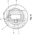
- FIGS. 5 to 16 show the operation of the locking device 1 based on the FIGS. 5 to 16 be explained in more detail. It shows the Fig. 6 a longitudinal section along the line 6-6 according to Fig. 5 essentially in the area of the worm wheel 12. Die Fig. 5 shows a cross section substantially through the worm wheel 12 in the region of the securing means 13 along the line 5-5 according to Fig. 6 , The others FIGS. 7 to 16 also show corresponding longitudinal or cross sections.
- such a locking device 1 can be found not only as a steering wheel lock on the steering column but also on any other functionally relevant component and / or operating unit of the motor vehicle use.
- a component and / or operating unit can be, for example, the transmission shift lever, the selector lever for an automatic transmission, the starter or the like.
- a locking device 1 also at another lock, for example, in a door lock for the motor vehicle, for a property o. The like., Use find.
Claims (10)
- Dispositif de verrouillage, en particulier verrou électrique de direction pour véhicule automobile, comprenant un élément d'arrêt (7) mobile entre une première et une seconde position pour verrouiller un composant fonctionnel, tel que l'arbre de direction (4) dans la colonne de direction (3) ou le levier de changement de vitesses, l'élément d'arrêt (7) se trouvant dans la première position en contact à effet bloquante avec le composant et/ou pouvant être amené en contact par blocage avec le composant et dans la seconde position, ne se trouvant pas en contact avec le composant, un dispositif d'entraînement (9) pour le déplacement de l'élément d'arrêt (7) entre les deux positions, et un moyen de fixation (13) pour fixer l'élément d'arrêt (7) dans la première position, en particulier à la manière d'une sécurisation de pression pour l'élément d'arrêt (7) se trouvant dans la première position afin d'empêcher les manipulations, le moyen de fixation (13) étant agencé dans l'élément d'arrêt (7), caractérisé en ce que le moyen de fixation (13) est une tige et en ce que le moyen de fixation (13) est monté coulissant en translation dans un logement (15) de l'élément d'arrêt (7).
- Dispositif de verrouillage selon la revendication 1, caractérisé en ce que le moyen de fixation (13) est mobile par rapport à l'élément d'arrêt (7) entre une position de fixation et une position de libération, de préférence le moyen de fixation (13) est adapté pour que, en position de fixation, l'élément d'arrêt (7) se trouvant en contact à effet bloquant avec le composant empêche le mouvement dans la direction de la seconde position, tant que l'élément d'arrêt (7) n'est pas déplacé au moyen de l'entraînement (9).
- Dispositif de verrouillage selon la revendication 1 ou 2, caractérisé en ce que le moyen de fixation (13) est soumis à une force élastique, en particulier au moyen d'un ressort (14), dans le sens de la position de fixation.
- Dispositif de verrouillage selon la revendication 1, 2 ou 3, caractérisé en ce que la tige (13) a une section transversale sensiblement circulaire, en ce que de préférence, le logement (15) de la tige (13) est un alésage (15) dans l'élément d'arrêt (7), et en ce que, plus préférablement encore, le moyen de fixation (13) est constitué de métal.
- Dispositif de verrouillage selon l'une des revendications 1 à 4, caractérisé en ce que le dispositif comporte un boîtier (10) et en ce que de préférence, une zone d'enclenchement (16) pour le moyen de fixation (13) est ménagée sur une partie fixe du boîtier, de sorte que le moyen de fixation (13) dans la position de verrouillage vienne s'engager dans la zone d'encliquetage (16) lorsque l'élément d'arrêt (7) se trouve en contact à effet bloquant avec le composant, en verrouillant son mouvement.
- Dispositif de verrouillage selon l'une des revendications 1 à 5, caractérisé en ce que le boîtier (10) est constitué d'un fond (11) et d'un couvercle, en ce que de préférence le fond (11) est en métal, et en ce que, de préférence, la partie fixe du boitier est le fond (11), en particulier que la zone d'encliquetage (16) est située dans le fond (11).
- Dispositif de verrouillage selon l'une des revendications 1 à 6, caractérisé en ce que le dispositif d'entraînement (9) comprend un moteur électrique ainsi qu'un élément de transmission (12), en particulier une roue à vis sans fin, pour déplacer l'élément d'arrêt (7), en ce que, de préférence l'élément de transmission (12) tourne autour d'un axe de rotation (20) au moyen du moteur électrique, et en ce que, de préférence encore, l'élément d'arrêt (7) est articulé sur l'élément de transmission (12) de sorte que l'élément d'arrêt (7) puisse se déplacer en translation dans la direction de l'axe de rotation (20) entre la première et la seconde position lorsque l'élément de transmission (12) tourne dans le sens de rotation respectif.
- Dispositif de verrouillage selon l'une des revendications 1 à 7, caractérisé en ce qu'une came de commande (17) pour le déplacement du moyen de fixation (13) entre la position de fixation et la position de libération coopère avec le dispositif d'entraînement (9), de telle sorte que le moyen de fixation (13) soit amené dans la position de fixation par la came de commande (17) lors du déplacement de l'élément d'arrêt (7) dans la première position, en particulier soit libéré pour s'encliqueter dans la zone d'encliquetage (16), et soit amené dans la position de libération par la came de commande (17) lors du déplacement de l'élément d'arrêt (7) dans la seconde position, en particulier soit délogé de la zone d'encliquetage (16), et en ce que, de préférence, la came de commande (17) pour le moyen de fixation (13) se trouve sur la roue à vis sans fin (12).
- Dispositif de verrouillage selon l'une des revendications 1 à 8, caractérisé en ce que la came de commande (17) comprend un premier segment (27) associé à la position de fixation et un second segment (28) associé à la position de libération, en ce que de préférence le second segment (28) est conçu sous la forme d'une bande circulaire disposée de manière concentrique à l'axe de rotation (20) pour le guidage du moyen de fixation (13), et en ce que de préférence, le premier segment (27) est une courbe (29) devenant une première bande circulaire (27) sortant de la seconde bande circulaire (28) de manière concentrique à l'axe de rotation (20), pour le guidage du moyen de fixation (13).
- Dispositif de verrouillage selon l'une des revendications 1 à 9, caractérisé en ce que l'arbre de direction (4) dans la colonne de direction (3) présente au moins une position d'encliquetage (8), en particulier plusieurs positions d'encliquetage (8) à la manière d'une couronne dentée pour l'élément d'arrêt (7) afin de bloquer le mouvement de rotation de l'arbre de direction (4).
Applications Claiming Priority (2)
| Application Number | Priority Date | Filing Date | Title |
|---|---|---|---|
| DE102014017639 | 2014-12-01 | ||
| PCT/EP2015/078163 WO2016087420A1 (fr) | 2014-12-01 | 2015-12-01 | Dispositif de verrouillage pour un véhicule automobile |
Publications (2)
| Publication Number | Publication Date |
|---|---|
| EP3227147A1 EP3227147A1 (fr) | 2017-10-11 |
| EP3227147B1 true EP3227147B1 (fr) | 2019-11-20 |
Family
ID=54771102
Family Applications (1)
| Application Number | Title | Priority Date | Filing Date |
|---|---|---|---|
| EP15804108.7A Active EP3227147B1 (fr) | 2014-12-01 | 2015-12-01 | Dispositif de verrouillage pour un véhicule |
Country Status (5)
| Country | Link |
|---|---|
| EP (1) | EP3227147B1 (fr) |
| CN (1) | CN107396633B (fr) |
| DE (1) | DE102015015221A1 (fr) |
| ES (1) | ES2773462T3 (fr) |
| WO (1) | WO2016087420A1 (fr) |
Families Citing this family (2)
| Publication number | Priority date | Publication date | Assignee | Title |
|---|---|---|---|---|
| CN109591759B (zh) * | 2019-01-30 | 2020-04-17 | 德州职业技术学院(德州市技师学院) | 一种汽车机械防盗锁 |
| DE102019009036A1 (de) * | 2019-12-31 | 2021-07-01 | Marquardt Gmbh | Verriegelungseinrichtung, insbesondere für ein Kraftfahrzeug |
Family Cites Families (9)
| Publication number | Priority date | Publication date | Assignee | Title |
|---|---|---|---|---|
| DE703539C (de) * | 1935-05-19 | 1941-03-11 | Abram Neiman | Sicherungsvorrichtung gegen Diebstahl von Fahrzeugen, insbesondere Kraftfahrzeugen |
| FR1240060A (fr) * | 1959-07-23 | 1960-09-02 | Dispositif antivol, notamment pour automobiles, motos et similaires | |
| GB1552681A (en) * | 1976-09-15 | 1979-09-19 | Neiman Security Prod | Anti theft lock for vehicles |
| DE4434587B4 (de) | 1993-10-01 | 2004-12-16 | Marquardt Gmbh | Elektronisches Zündstartschloßsystem an einem Kraftfahrzeug |
| DE4436326C1 (de) * | 1994-10-11 | 1995-10-19 | Huelsbeck & Fuerst | Schloß, insbesondere zum Verriegeln der Lenkspindel oder der Zahnstange des Lenkgetriebes oder der Ausgangswelle des Antriebsgetriebes eines Kraftfahrzeugs |
| DE10320138B3 (de) * | 2003-05-06 | 2005-01-13 | Huf Hülsbeck & Fürst Gmbh & Co. Kg | Vorrichtung zum Sperren der Lenkspindel eines Kraftfahrzeugs |
| DE102008031217B4 (de) * | 2008-07-03 | 2020-05-07 | Huf Hülsbeck & Fürst Gmbh & Co. Kg | Sperrvorrichtung mit einem Sperrglied zur Sperrung eines funktionswesentlichen Bauteils |
| CN202324872U (zh) * | 2011-10-21 | 2012-07-11 | 国电南瑞科技股份有限公司 | 电动锁闭装置 |
| DE102012016933A1 (de) * | 2011-12-17 | 2013-06-20 | Marquardt Gmbh | Verrieglungseinrichtung für ein Fahrzeug, Fahrzeug und Verfahren zum Sichern eines Fahrzeugs |
-
2015
- 2015-11-27 DE DE102015015221.1A patent/DE102015015221A1/de not_active Withdrawn
- 2015-12-01 CN CN201580065349.6A patent/CN107396633B/zh active Active
- 2015-12-01 ES ES15804108T patent/ES2773462T3/es active Active
- 2015-12-01 WO PCT/EP2015/078163 patent/WO2016087420A1/fr active Application Filing
- 2015-12-01 EP EP15804108.7A patent/EP3227147B1/fr active Active
Non-Patent Citations (1)
| Title |
|---|
| None * |
Also Published As
| Publication number | Publication date |
|---|---|
| CN107396633B (zh) | 2020-10-30 |
| ES2773462T3 (es) | 2020-07-13 |
| CN107396633A (zh) | 2017-11-24 |
| DE102015015221A1 (de) | 2016-06-02 |
| WO2016087420A1 (fr) | 2016-06-09 |
| EP3227147A1 (fr) | 2017-10-11 |
Similar Documents
| Publication | Publication Date | Title |
|---|---|---|
| EP2539188B1 (fr) | Dispositif de blocage de direction pour véhicule | |
| EP3621855B1 (fr) | Dispositif de verrouillage, en particulier pour un véhicule à moteur | |
| DE10133408A1 (de) | Verriegelungseinrichtung, insbesondere für ein Kraftfahrzeug | |
| WO2010004045A2 (fr) | Procédé servant à commander le système de direction d'une moto | |
| EP1135284B1 (fr) | Systeme de fermeture, notamment pour automobiles | |
| DE102013012117A1 (de) | Fahrzeugschloss mit Zuzieheinrichtung sowie Fahrzeug mit einem derartigen Fahrzeugschloss | |
| EP3227147B1 (fr) | Dispositif de verrouillage pour un véhicule | |
| EP2300281B1 (fr) | Dispositif servant à commander un élément de blocage | |
| WO2019206370A1 (fr) | Serrure de véhicule automobile | |
| EP2642049A2 (fr) | Manipulation d'un véhicule automobile doté d'un élément de recouvrement mobile | |
| DE10107992B4 (de) | Zündschloßsystem für ein Kraftfahrzeug | |
| WO2002027123A1 (fr) | Serrure de contact pour un vehicule automobile | |
| DE102005025834A1 (de) | Elektrische Lenkungsverriegelung, insbesondere für ein Kraftfahrzeug | |
| DE4442789B4 (de) | Verriegelungssystem, insbesondere für ein Betriebsaggregat an einem Kraftfahrzeug | |
| DE10022831B4 (de) | Verriegelungseinrichtung, insbesondere für ein Kraftfahrzeug | |
| DE102020106126A1 (de) | Kraftfahrzeugschloss | |
| DE19634627C1 (de) | Lenkradsperre für ein Kraftfahrzeug mit Wegfahrsperre | |
| DE10022830B4 (de) | Verriegelungseinrichtung, insbesondere für ein Kraftfahrzeug | |
| EP1602538B1 (fr) | Verrou electrique de direction, en particulier pour véhicule. | |
| EP2117887B1 (fr) | Dispositif d'asservissement d'un organe de blocage | |
| DE102014016895A1 (de) | Verriegelungseinrichtung, insbesondere für ein Kraftfahrzeug | |
| WO2021136690A1 (fr) | Dispositif de blocage, en particulier pour un véhicule à moteur | |
| DE102007002451A1 (de) | Vorrichtung zur Ansteuerung eines Sperrgliedes | |
| DE102014000482A1 (de) | Gehäuse, insbesondere für einen elektronischen Schlüssel | |
| DE102021122944A1 (de) | Kraftfahrzeugschloss |
Legal Events
| Date | Code | Title | Description |
|---|---|---|---|
| STAA | Information on the status of an ep patent application or granted ep patent |
Free format text: STATUS: THE INTERNATIONAL PUBLICATION HAS BEEN MADE |
|
| PUAI | Public reference made under article 153(3) epc to a published international application that has entered the european phase |
Free format text: ORIGINAL CODE: 0009012 |
|
| STAA | Information on the status of an ep patent application or granted ep patent |
Free format text: STATUS: REQUEST FOR EXAMINATION WAS MADE |
|
| 17P | Request for examination filed |
Effective date: 20170512 |
|
| AK | Designated contracting states |
Kind code of ref document: A1 Designated state(s): AL AT BE BG CH CY CZ DE DK EE ES FI FR GB GR HR HU IE IS IT LI LT LU LV MC MK MT NL NO PL PT RO RS SE SI SK SM TR |
|
| AX | Request for extension of the european patent |
Extension state: BA ME |
|
| DAV | Request for validation of the european patent (deleted) | ||
| DAX | Request for extension of the european patent (deleted) | ||
| GRAP | Despatch of communication of intention to grant a patent |
Free format text: ORIGINAL CODE: EPIDOSNIGR1 |
|
| STAA | Information on the status of an ep patent application or granted ep patent |
Free format text: STATUS: GRANT OF PATENT IS INTENDED |
|
| INTG | Intention to grant announced |
Effective date: 20190718 |
|
| GRAS | Grant fee paid |
Free format text: ORIGINAL CODE: EPIDOSNIGR3 |
|
| GRAA | (expected) grant |
Free format text: ORIGINAL CODE: 0009210 |
|
| STAA | Information on the status of an ep patent application or granted ep patent |
Free format text: STATUS: THE PATENT HAS BEEN GRANTED |
|
| AK | Designated contracting states |
Kind code of ref document: B1 Designated state(s): AL AT BE BG CH CY CZ DE DK EE ES FI FR GB GR HR HU IE IS IT LI LT LU LV MC MK MT NL NO PL PT RO RS SE SI SK SM TR |
|
| REG | Reference to a national code |
Ref country code: GB Ref legal event code: FG4D Free format text: NOT ENGLISH |
|
| REG | Reference to a national code |
Ref country code: CH Ref legal event code: EP |
|
| REG | Reference to a national code |
Ref country code: IE Ref legal event code: FG4D Free format text: LANGUAGE OF EP DOCUMENT: GERMAN |
|
| REG | Reference to a national code |
Ref country code: DE Ref legal event code: R096 Ref document number: 502015011022 Country of ref document: DE |
|
| REG | Reference to a national code |
Ref country code: AT Ref legal event code: REF Ref document number: 1203829 Country of ref document: AT Kind code of ref document: T Effective date: 20191215 |
|
| REG | Reference to a national code |
Ref country code: SE Ref legal event code: TRGR |
|
| REG | Reference to a national code |
Ref country code: NL Ref legal event code: MP Effective date: 20191120 |
|
| REG | Reference to a national code |
Ref country code: SK Ref legal event code: T3 Ref document number: E 33226 Country of ref document: SK |
|
| REG | Reference to a national code |
Ref country code: LT Ref legal event code: MG4D |
|
| PG25 | Lapsed in a contracting state [announced via postgrant information from national office to epo] |
Ref country code: NO Free format text: LAPSE BECAUSE OF FAILURE TO SUBMIT A TRANSLATION OF THE DESCRIPTION OR TO PAY THE FEE WITHIN THE PRESCRIBED TIME-LIMIT Effective date: 20200220 Ref country code: BG Free format text: LAPSE BECAUSE OF FAILURE TO SUBMIT A TRANSLATION OF THE DESCRIPTION OR TO PAY THE FEE WITHIN THE PRESCRIBED TIME-LIMIT Effective date: 20200220 Ref country code: FI Free format text: LAPSE BECAUSE OF FAILURE TO SUBMIT A TRANSLATION OF THE DESCRIPTION OR TO PAY THE FEE WITHIN THE PRESCRIBED TIME-LIMIT Effective date: 20191120 Ref country code: NL Free format text: LAPSE BECAUSE OF FAILURE TO SUBMIT A TRANSLATION OF THE DESCRIPTION OR TO PAY THE FEE WITHIN THE PRESCRIBED TIME-LIMIT Effective date: 20191120 Ref country code: LV Free format text: LAPSE BECAUSE OF FAILURE TO SUBMIT A TRANSLATION OF THE DESCRIPTION OR TO PAY THE FEE WITHIN THE PRESCRIBED TIME-LIMIT Effective date: 20191120 Ref country code: GR Free format text: LAPSE BECAUSE OF FAILURE TO SUBMIT A TRANSLATION OF THE DESCRIPTION OR TO PAY THE FEE WITHIN THE PRESCRIBED TIME-LIMIT Effective date: 20200221 Ref country code: LT Free format text: LAPSE BECAUSE OF FAILURE TO SUBMIT A TRANSLATION OF THE DESCRIPTION OR TO PAY THE FEE WITHIN THE PRESCRIBED TIME-LIMIT Effective date: 20191120 |
|
| PG25 | Lapsed in a contracting state [announced via postgrant information from national office to epo] |
Ref country code: IS Free format text: LAPSE BECAUSE OF FAILURE TO SUBMIT A TRANSLATION OF THE DESCRIPTION OR TO PAY THE FEE WITHIN THE PRESCRIBED TIME-LIMIT Effective date: 20200320 Ref country code: HR Free format text: LAPSE BECAUSE OF FAILURE TO SUBMIT A TRANSLATION OF THE DESCRIPTION OR TO PAY THE FEE WITHIN THE PRESCRIBED TIME-LIMIT Effective date: 20191120 Ref country code: RS Free format text: LAPSE BECAUSE OF FAILURE TO SUBMIT A TRANSLATION OF THE DESCRIPTION OR TO PAY THE FEE WITHIN THE PRESCRIBED TIME-LIMIT Effective date: 20191120 |
|
| PG25 | Lapsed in a contracting state [announced via postgrant information from national office to epo] |
Ref country code: AL Free format text: LAPSE BECAUSE OF FAILURE TO SUBMIT A TRANSLATION OF THE DESCRIPTION OR TO PAY THE FEE WITHIN THE PRESCRIBED TIME-LIMIT Effective date: 20191120 |
|
| REG | Reference to a national code |
Ref country code: ES Ref legal event code: FG2A Ref document number: 2773462 Country of ref document: ES Kind code of ref document: T3 Effective date: 20200713 |
|
| PG25 | Lapsed in a contracting state [announced via postgrant information from national office to epo] |
Ref country code: EE Free format text: LAPSE BECAUSE OF FAILURE TO SUBMIT A TRANSLATION OF THE DESCRIPTION OR TO PAY THE FEE WITHIN THE PRESCRIBED TIME-LIMIT Effective date: 20191120 Ref country code: DK Free format text: LAPSE BECAUSE OF FAILURE TO SUBMIT A TRANSLATION OF THE DESCRIPTION OR TO PAY THE FEE WITHIN THE PRESCRIBED TIME-LIMIT Effective date: 20191120 Ref country code: PT Free format text: LAPSE BECAUSE OF FAILURE TO SUBMIT A TRANSLATION OF THE DESCRIPTION OR TO PAY THE FEE WITHIN THE PRESCRIBED TIME-LIMIT Effective date: 20200412 Ref country code: RO Free format text: LAPSE BECAUSE OF FAILURE TO SUBMIT A TRANSLATION OF THE DESCRIPTION OR TO PAY THE FEE WITHIN THE PRESCRIBED TIME-LIMIT Effective date: 20191120 |
|
| REG | Reference to a national code |
Ref country code: CH Ref legal event code: PL |
|
| REG | Reference to a national code |
Ref country code: DE Ref legal event code: R097 Ref document number: 502015011022 Country of ref document: DE |
|
| REG | Reference to a national code |
Ref country code: BE Ref legal event code: MM Effective date: 20191231 |
|
| PG25 | Lapsed in a contracting state [announced via postgrant information from national office to epo] |
Ref country code: SM Free format text: LAPSE BECAUSE OF FAILURE TO SUBMIT A TRANSLATION OF THE DESCRIPTION OR TO PAY THE FEE WITHIN THE PRESCRIBED TIME-LIMIT Effective date: 20191120 Ref country code: MC Free format text: LAPSE BECAUSE OF FAILURE TO SUBMIT A TRANSLATION OF THE DESCRIPTION OR TO PAY THE FEE WITHIN THE PRESCRIBED TIME-LIMIT Effective date: 20191120 |
|
| PLBE | No opposition filed within time limit |
Free format text: ORIGINAL CODE: 0009261 |
|
| STAA | Information on the status of an ep patent application or granted ep patent |
Free format text: STATUS: NO OPPOSITION FILED WITHIN TIME LIMIT |
|
| 26N | No opposition filed |
Effective date: 20200821 |
|
| PG25 | Lapsed in a contracting state [announced via postgrant information from national office to epo] |
Ref country code: IE Free format text: LAPSE BECAUSE OF NON-PAYMENT OF DUE FEES Effective date: 20191201 Ref country code: LU Free format text: LAPSE BECAUSE OF NON-PAYMENT OF DUE FEES Effective date: 20191201 |
|
| REG | Reference to a national code |
Ref country code: DE Ref legal event code: R082 Ref document number: 502015011022 Country of ref document: DE Representative=s name: JOSTARNDT PATENTANWALTS-AG, DE |
|
| PG25 | Lapsed in a contracting state [announced via postgrant information from national office to epo] |
Ref country code: CH Free format text: LAPSE BECAUSE OF NON-PAYMENT OF DUE FEES Effective date: 20191231 Ref country code: LI Free format text: LAPSE BECAUSE OF NON-PAYMENT OF DUE FEES Effective date: 20191231 Ref country code: BE Free format text: LAPSE BECAUSE OF NON-PAYMENT OF DUE FEES Effective date: 20191231 Ref country code: SI Free format text: LAPSE BECAUSE OF FAILURE TO SUBMIT A TRANSLATION OF THE DESCRIPTION OR TO PAY THE FEE WITHIN THE PRESCRIBED TIME-LIMIT Effective date: 20191120 Ref country code: PL Free format text: LAPSE BECAUSE OF FAILURE TO SUBMIT A TRANSLATION OF THE DESCRIPTION OR TO PAY THE FEE WITHIN THE PRESCRIBED TIME-LIMIT Effective date: 20191120 |
|
| PG25 | Lapsed in a contracting state [announced via postgrant information from national office to epo] |
Ref country code: CY Free format text: LAPSE BECAUSE OF FAILURE TO SUBMIT A TRANSLATION OF THE DESCRIPTION OR TO PAY THE FEE WITHIN THE PRESCRIBED TIME-LIMIT Effective date: 20191120 |
|
| PG25 | Lapsed in a contracting state [announced via postgrant information from national office to epo] |
Ref country code: MT Free format text: LAPSE BECAUSE OF FAILURE TO SUBMIT A TRANSLATION OF THE DESCRIPTION OR TO PAY THE FEE WITHIN THE PRESCRIBED TIME-LIMIT Effective date: 20191120 Ref country code: HU Free format text: LAPSE BECAUSE OF FAILURE TO SUBMIT A TRANSLATION OF THE DESCRIPTION OR TO PAY THE FEE WITHIN THE PRESCRIBED TIME-LIMIT; INVALID AB INITIO Effective date: 20151201 |
|
| REG | Reference to a national code |
Ref country code: AT Ref legal event code: MM01 Ref document number: 1203829 Country of ref document: AT Kind code of ref document: T Effective date: 20201201 |
|
| PG25 | Lapsed in a contracting state [announced via postgrant information from national office to epo] |
Ref country code: AT Free format text: LAPSE BECAUSE OF NON-PAYMENT OF DUE FEES Effective date: 20201201 |
|
| PG25 | Lapsed in a contracting state [announced via postgrant information from national office to epo] |
Ref country code: TR Free format text: LAPSE BECAUSE OF FAILURE TO SUBMIT A TRANSLATION OF THE DESCRIPTION OR TO PAY THE FEE WITHIN THE PRESCRIBED TIME-LIMIT Effective date: 20191120 |
|
| PG25 | Lapsed in a contracting state [announced via postgrant information from national office to epo] |
Ref country code: MK Free format text: LAPSE BECAUSE OF FAILURE TO SUBMIT A TRANSLATION OF THE DESCRIPTION OR TO PAY THE FEE WITHIN THE PRESCRIBED TIME-LIMIT Effective date: 20191120 |
|
| REG | Reference to a national code |
Ref country code: DE Ref legal event code: R082 Ref document number: 502015011022 Country of ref document: DE |
|
| PGFP | Annual fee paid to national office [announced via postgrant information from national office to epo] |
Ref country code: ES Payment date: 20230119 Year of fee payment: 8 |
|
| PGFP | Annual fee paid to national office [announced via postgrant information from national office to epo] |
Ref country code: IT Payment date: 20221230 Year of fee payment: 8 |
|
| P01 | Opt-out of the competence of the unified patent court (upc) registered |
Effective date: 20230522 |
|
| PGFP | Annual fee paid to national office [announced via postgrant information from national office to epo] |
Ref country code: SK Payment date: 20231120 Year of fee payment: 9 |
|
| PGFP | Annual fee paid to national office [announced via postgrant information from national office to epo] |
Ref country code: GB Payment date: 20231220 Year of fee payment: 9 |
|
| PGFP | Annual fee paid to national office [announced via postgrant information from national office to epo] |
Ref country code: SE Payment date: 20231219 Year of fee payment: 9 Ref country code: FR Payment date: 20231219 Year of fee payment: 9 Ref country code: DE Payment date: 20231214 Year of fee payment: 9 Ref country code: CZ Payment date: 20231120 Year of fee payment: 9 |
|
| PGFP | Annual fee paid to national office [announced via postgrant information from national office to epo] |
Ref country code: ES Payment date: 20240118 Year of fee payment: 9 |