EP3226781B1 - Élimination de volume assistée par robot pendant une intervention chirurgicale - Google Patents
Élimination de volume assistée par robot pendant une intervention chirurgicale Download PDFInfo
- Publication number
- EP3226781B1 EP3226781B1 EP15816096.0A EP15816096A EP3226781B1 EP 3226781 B1 EP3226781 B1 EP 3226781B1 EP 15816096 A EP15816096 A EP 15816096A EP 3226781 B1 EP3226781 B1 EP 3226781B1
- Authority
- EP
- European Patent Office
- Prior art keywords
- surgical instrument
- instrument holder
- holder
- surgical
- robot
- Prior art date
- Legal status (The legal status is an assumption and is not a legal conclusion. Google has not performed a legal analysis and makes no representation as to the accuracy of the status listed.)
- Active
Links
- 238000001356 surgical procedure Methods 0.000 title claims description 44
- 230000033001 locomotion Effects 0.000 claims description 42
- 239000012636 effector Substances 0.000 claims description 16
- 238000003801 milling Methods 0.000 claims description 9
- 230000008878 coupling Effects 0.000 claims description 7
- 238000010168 coupling process Methods 0.000 claims description 7
- 238000005859 coupling reaction Methods 0.000 claims description 7
- 238000005259 measurement Methods 0.000 claims description 7
- 238000000034 method Methods 0.000 description 48
- 230000015654 memory Effects 0.000 description 35
- 239000003550 marker Substances 0.000 description 17
- 230000007246 mechanism Effects 0.000 description 17
- 238000005516 engineering process Methods 0.000 description 15
- 238000004891 communication Methods 0.000 description 13
- 230000008569 process Effects 0.000 description 13
- 210000000988 bone and bone Anatomy 0.000 description 12
- 230000011218 segmentation Effects 0.000 description 9
- 230000000087 stabilizing effect Effects 0.000 description 9
- 210000003484 anatomy Anatomy 0.000 description 8
- 210000001519 tissue Anatomy 0.000 description 8
- 230000003287 optical effect Effects 0.000 description 7
- 238000012512 characterization method Methods 0.000 description 6
- 238000005553 drilling Methods 0.000 description 6
- 238000004590 computer program Methods 0.000 description 4
- 230000003993 interaction Effects 0.000 description 4
- 238000012545 processing Methods 0.000 description 4
- 230000001413 cellular effect Effects 0.000 description 3
- 238000010586 diagram Methods 0.000 description 3
- 230000006870 function Effects 0.000 description 3
- 206010028980 Neoplasm Diseases 0.000 description 2
- 230000009471 action Effects 0.000 description 2
- 230000004913 activation Effects 0.000 description 2
- 230000006399 behavior Effects 0.000 description 2
- 230000008901 benefit Effects 0.000 description 2
- 230000008859 change Effects 0.000 description 2
- 239000003086 colorant Substances 0.000 description 2
- 238000012937 correction Methods 0.000 description 2
- 238000007428 craniotomy Methods 0.000 description 2
- 230000006378 damage Effects 0.000 description 2
- 238000001514 detection method Methods 0.000 description 2
- 238000003384 imaging method Methods 0.000 description 2
- 239000004973 liquid crystal related substance Substances 0.000 description 2
- 238000012544 monitoring process Methods 0.000 description 2
- 230000000399 orthopedic effect Effects 0.000 description 2
- 230000003252 repetitive effect Effects 0.000 description 2
- 210000000278 spinal cord Anatomy 0.000 description 2
- 208000005198 spinal stenosis Diseases 0.000 description 2
- 230000006641 stabilisation Effects 0.000 description 2
- 238000011105 stabilization Methods 0.000 description 2
- 238000012546 transfer Methods 0.000 description 2
- 238000009966 trimming Methods 0.000 description 2
- 208000012514 Cumulative Trauma disease Diseases 0.000 description 1
- 241000761557 Lamina Species 0.000 description 1
- 206010044565 Tremor Diseases 0.000 description 1
- 238000013459 approach Methods 0.000 description 1
- 238000004883 computer application Methods 0.000 description 1
- 238000012790 confirmation Methods 0.000 description 1
- 230000003247 decreasing effect Effects 0.000 description 1
- 238000003745 diagnosis Methods 0.000 description 1
- 238000002059 diagnostic imaging Methods 0.000 description 1
- 238000006073 displacement reaction Methods 0.000 description 1
- 210000001951 dura mater Anatomy 0.000 description 1
- 230000003670 easy-to-clean Effects 0.000 description 1
- 238000003708 edge detection Methods 0.000 description 1
- 230000000694 effects Effects 0.000 description 1
- 238000002594 fluoroscopy Methods 0.000 description 1
- 238000003709 image segmentation Methods 0.000 description 1
- 239000007943 implant Substances 0.000 description 1
- 230000006872 improvement Effects 0.000 description 1
- 238000003780 insertion Methods 0.000 description 1
- 230000037431 insertion Effects 0.000 description 1
- 238000013507 mapping Methods 0.000 description 1
- 239000000463 material Substances 0.000 description 1
- 239000011159 matrix material Substances 0.000 description 1
- 238000010295 mobile communication Methods 0.000 description 1
- 238000012806 monitoring device Methods 0.000 description 1
- 210000000653 nervous system Anatomy 0.000 description 1
- 230000006855 networking Effects 0.000 description 1
- 238000010422 painting Methods 0.000 description 1
- 238000003825 pressing Methods 0.000 description 1
- 230000000644 propagated effect Effects 0.000 description 1
- 230000001012 protector Effects 0.000 description 1
- 230000004044 response Effects 0.000 description 1
- 230000001953 sensory effect Effects 0.000 description 1
- 239000007787 solid Substances 0.000 description 1
- 210000000273 spinal nerve root Anatomy 0.000 description 1
- 230000001954 sterilising effect Effects 0.000 description 1
- 238000004659 sterilization and disinfection Methods 0.000 description 1
- 239000013589 supplement Substances 0.000 description 1
- 238000013519 translation Methods 0.000 description 1
- 230000014616 translation Effects 0.000 description 1
- 230000005945 translocation Effects 0.000 description 1
- 238000002604 ultrasonography Methods 0.000 description 1
- 230000000007 visual effect Effects 0.000 description 1
- 210000002517 zygapophyseal joint Anatomy 0.000 description 1
Images


Classifications
-
- A—HUMAN NECESSITIES
- A61—MEDICAL OR VETERINARY SCIENCE; HYGIENE
- A61B—DIAGNOSIS; SURGERY; IDENTIFICATION
- A61B34/00—Computer-aided surgery; Manipulators or robots specially adapted for use in surgery
- A61B34/30—Surgical robots
-
- A—HUMAN NECESSITIES
- A61—MEDICAL OR VETERINARY SCIENCE; HYGIENE
- A61B—DIAGNOSIS; SURGERY; IDENTIFICATION
- A61B17/00—Surgical instruments, devices or methods, e.g. tourniquets
- A61B17/16—Bone cutting, breaking or removal means other than saws, e.g. Osteoclasts; Drills or chisels for bones; Trepans
- A61B17/1662—Bone cutting, breaking or removal means other than saws, e.g. Osteoclasts; Drills or chisels for bones; Trepans for particular parts of the body
- A61B17/1671—Bone cutting, breaking or removal means other than saws, e.g. Osteoclasts; Drills or chisels for bones; Trepans for particular parts of the body for the spine
-
- A—HUMAN NECESSITIES
- A61—MEDICAL OR VETERINARY SCIENCE; HYGIENE
- A61B—DIAGNOSIS; SURGERY; IDENTIFICATION
- A61B90/00—Instruments, implements or accessories specially adapted for surgery or diagnosis and not covered by any of the groups A61B1/00 - A61B50/00, e.g. for luxation treatment or for protecting wound edges
- A61B90/50—Supports for surgical instruments, e.g. articulated arms
-
- A—HUMAN NECESSITIES
- A61—MEDICAL OR VETERINARY SCIENCE; HYGIENE
- A61B—DIAGNOSIS; SURGERY; IDENTIFICATION
- A61B17/00—Surgical instruments, devices or methods, e.g. tourniquets
- A61B17/16—Bone cutting, breaking or removal means other than saws, e.g. Osteoclasts; Drills or chisels for bones; Trepans
- A61B17/17—Guides or aligning means for drills, mills, pins or wires
- A61B17/1739—Guides or aligning means for drills, mills, pins or wires specially adapted for particular parts of the body
- A61B17/1757—Guides or aligning means for drills, mills, pins or wires specially adapted for particular parts of the body for the spine
-
- A—HUMAN NECESSITIES
- A61—MEDICAL OR VETERINARY SCIENCE; HYGIENE
- A61B—DIAGNOSIS; SURGERY; IDENTIFICATION
- A61B17/00—Surgical instruments, devices or methods, e.g. tourniquets
- A61B17/34—Trocars; Puncturing needles
- A61B17/3403—Needle locating or guiding means
-
- A—HUMAN NECESSITIES
- A61—MEDICAL OR VETERINARY SCIENCE; HYGIENE
- A61B—DIAGNOSIS; SURGERY; IDENTIFICATION
- A61B17/00—Surgical instruments, devices or methods, e.g. tourniquets
- A61B2017/00017—Electrical control of surgical instruments
-
- A—HUMAN NECESSITIES
- A61—MEDICAL OR VETERINARY SCIENCE; HYGIENE
- A61B—DIAGNOSIS; SURGERY; IDENTIFICATION
- A61B17/00—Surgical instruments, devices or methods, e.g. tourniquets
- A61B2017/00017—Electrical control of surgical instruments
- A61B2017/00115—Electrical control of surgical instruments with audible or visual output
- A61B2017/00119—Electrical control of surgical instruments with audible or visual output alarm; indicating an abnormal situation
- A61B2017/00123—Electrical control of surgical instruments with audible or visual output alarm; indicating an abnormal situation and automatic shutdown
-
- A—HUMAN NECESSITIES
- A61—MEDICAL OR VETERINARY SCIENCE; HYGIENE
- A61B—DIAGNOSIS; SURGERY; IDENTIFICATION
- A61B17/00—Surgical instruments, devices or methods, e.g. tourniquets
- A61B2017/00017—Electrical control of surgical instruments
- A61B2017/00203—Electrical control of surgical instruments with speech control or speech recognition
-
- A—HUMAN NECESSITIES
- A61—MEDICAL OR VETERINARY SCIENCE; HYGIENE
- A61B—DIAGNOSIS; SURGERY; IDENTIFICATION
- A61B17/00—Surgical instruments, devices or methods, e.g. tourniquets
- A61B2017/00017—Electrical control of surgical instruments
- A61B2017/00207—Electrical control of surgical instruments with hand gesture control or hand gesture recognition
-
- A—HUMAN NECESSITIES
- A61—MEDICAL OR VETERINARY SCIENCE; HYGIENE
- A61B—DIAGNOSIS; SURGERY; IDENTIFICATION
- A61B17/00—Surgical instruments, devices or methods, e.g. tourniquets
- A61B2017/00477—Coupling
-
- A—HUMAN NECESSITIES
- A61—MEDICAL OR VETERINARY SCIENCE; HYGIENE
- A61B—DIAGNOSIS; SURGERY; IDENTIFICATION
- A61B34/00—Computer-aided surgery; Manipulators or robots specially adapted for use in surgery
- A61B34/10—Computer-aided planning, simulation or modelling of surgical operations
- A61B2034/107—Visualisation of planned trajectories or target regions
-
- A—HUMAN NECESSITIES
- A61—MEDICAL OR VETERINARY SCIENCE; HYGIENE
- A61B—DIAGNOSIS; SURGERY; IDENTIFICATION
- A61B34/00—Computer-aided surgery; Manipulators or robots specially adapted for use in surgery
- A61B34/20—Surgical navigation systems; Devices for tracking or guiding surgical instruments, e.g. for frameless stereotaxis
- A61B2034/2046—Tracking techniques
- A61B2034/2059—Mechanical position encoders
-
- A—HUMAN NECESSITIES
- A61—MEDICAL OR VETERINARY SCIENCE; HYGIENE
- A61B—DIAGNOSIS; SURGERY; IDENTIFICATION
- A61B34/00—Computer-aided surgery; Manipulators or robots specially adapted for use in surgery
- A61B34/20—Surgical navigation systems; Devices for tracking or guiding surgical instruments, e.g. for frameless stereotaxis
- A61B2034/2068—Surgical navigation systems; Devices for tracking or guiding surgical instruments, e.g. for frameless stereotaxis using pointers, e.g. pointers having reference marks for determining coordinates of body points
-
- A—HUMAN NECESSITIES
- A61—MEDICAL OR VETERINARY SCIENCE; HYGIENE
- A61B—DIAGNOSIS; SURGERY; IDENTIFICATION
- A61B90/00—Instruments, implements or accessories specially adapted for surgery or diagnosis and not covered by any of the groups A61B1/00 - A61B50/00, e.g. for luxation treatment or for protecting wound edges
- A61B90/06—Measuring instruments not otherwise provided for
- A61B2090/064—Measuring instruments not otherwise provided for for measuring force, pressure or mechanical tension
- A61B2090/066—Measuring instruments not otherwise provided for for measuring force, pressure or mechanical tension for measuring torque
-
- A—HUMAN NECESSITIES
- A61—MEDICAL OR VETERINARY SCIENCE; HYGIENE
- A61B—DIAGNOSIS; SURGERY; IDENTIFICATION
- A61B90/00—Instruments, implements or accessories specially adapted for surgery or diagnosis and not covered by any of the groups A61B1/00 - A61B50/00, e.g. for luxation treatment or for protecting wound edges
- A61B90/50—Supports for surgical instruments, e.g. articulated arms
- A61B2090/508—Supports for surgical instruments, e.g. articulated arms with releasable brake mechanisms
-
- A—HUMAN NECESSITIES
- A61—MEDICAL OR VETERINARY SCIENCE; HYGIENE
- A61B—DIAGNOSIS; SURGERY; IDENTIFICATION
- A61B2576/00—Medical imaging apparatus involving image processing or analysis
-
- A—HUMAN NECESSITIES
- A61—MEDICAL OR VETERINARY SCIENCE; HYGIENE
- A61B—DIAGNOSIS; SURGERY; IDENTIFICATION
- A61B34/00—Computer-aided surgery; Manipulators or robots specially adapted for use in surgery
- A61B34/25—User interfaces for surgical systems
-
- A—HUMAN NECESSITIES
- A61—MEDICAL OR VETERINARY SCIENCE; HYGIENE
- A61B—DIAGNOSIS; SURGERY; IDENTIFICATION
- A61B34/00—Computer-aided surgery; Manipulators or robots specially adapted for use in surgery
- A61B34/70—Manipulators specially adapted for use in surgery
- A61B34/76—Manipulators having means for providing feel, e.g. force or tactile feedback
Definitions
- Spinal stenosis (narrowing of the spinal canal) is the single most common diagnosis that leads to spinal surgery.
- a laminotomy may be performed to alleviate pain associated with spinal stenosis by partially removing/trimming the vertebra lamina shown in Fig. 1 , thereby decompressing the corresponding spinal cord and/or spinal nerve root.
- a surgeon manually removes portions of the lamina.
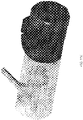
- the surgical instruments used for this task include surgical pliers and a high-speed burr as shown in Figs. 2A and 2B , respectively.
- Described herein is a device and method used to effectively remove volume inside a patient in various types of surgeries, such as spinal surgeries (e.g. laminotomy), neurosurgeries (various types of craniotomy), ENT surgeries (e.g. tumor removal), and orthopedic surgeries (bone removal).
- spinal surgeries e.g. laminotomy
- neurosurgeries various types of craniotomy
- ENT surgeries e.g. tumor removal
- orthopedic surgeries bone removal.
- the disclosed technology provides robotic assistance linked with a navigation system and medical imaging to shorten surgery time, make the surgery safer and free surgeons from doing repetitive and laborious tasks.
- the disclosed technology is also compatible with robotic surgical system described in U.S. Patent Application No. 2015/0100066, filed April 30, 2014 , and entitled "Apparatus, Systems, and Methods for Precise Guidance of Surgical Tool", thereby, for example, allowing the same robotic surgical system to assist with different aspects of spinal surgery.
- the invention relates to a surgical instrument holder for use with a robotic surgical system.
- the holder can be attached to or is part of an end effector of a robotic arm, and provides a rigid structure that can be used with a surgical tool to affect precise removal of a target volume in a patient.
- the holder has a tubular shape with a longitudinal notch along a portion of its length.
- the holder is sized to allow a surgical instrument to slide through the holder in a fixed orientation while the holder is held by the robotic arm.
- the surgical instrument in certain examples is fitted with a tool support having a peg sized to fit the notch.
- a navigational marker (e.g., a multipoint, planar marker) may be attached thereto via the peg.
- the navigation marker can be tracked (e.g., and hence the location of a surgical instrument connected to the navigation marker) when the surgical instrument is fully inserted and secured in the holder (e.g., in part by a locking mechanism). This facilitates and simplifies tracking of the marker, for example, via a remote tracking system that displays real-time tracking of the surgical instrument during the surgical procedure.
- the invention relates to an instrument holder with a rigid hollow tubular structure having a proximal open end and a distal open end, said structure defining an axis along which movement of a surgical instrument sliding through the structure is restricted, wherein the tubular structure has an interior surface shaped and sized to accommodate the surgical instrument sliding through the surgical instrument holder such that movement of the surgical instrument is constrained to move along the axis defined by the surgical instrument holder (e.g., thereby allowing rapid exchange of surgical instruments held by the surgical instrument holder); and a connector element attached to the holder that, when engaged (e.g., mated with) a corresponding connector element associated with a surgical instrument, provides power to the surgical instrument (e.g., and receives measurement information from a force sensor in the surgical instrument).
- a connector element attached to the holder that, when engaged (e.g., mated with) a corresponding connector element associated with a surgical instrument, provides power to the surgical instrument (e.g., and receives measurement information from
- the tubular structure has an exterior surface including at least one flange that is sized and shaped to secure coupling of the surgical instrument holder to an end effector of the robotic surgical system.
- the tubular structure includes a longitudinal notch along its length, wherein the longitudinal notch (e.g., slot) is sized in relation to a peg on (e.g., directly or indirectly) the surgical instrument to permit the surgical instrument to slide along the axis defined by the surgical instrument holder.
- the longitudinal notch is sized in relation to a peg to (i) permit a navigation marker attached to the surgical instrument at least in part via the peg to be viewable by a navigation camera along an entire range of movement of the surgical instrument through the surgical instrument holder, and (ii) constrain movement of the marker in a fixed orientation along the axis defined by the surgical instrument holder.
- navigation marker is used by navigation camera to track the surgical instrument.
- a lock that, when engaged, restricts (e.g., prevents) movement of a surgical instrument within the rigid hollow tubular structure (e.g., such that the surgical instrument is constrained within the tubular structure in all directions).
- the lock when engaged, prevents removal of the surgical instrument from the surgical instrument holder.
- a force sensor measures one or more forces and/or torques (e.g., 1 to 3 forces and 1 to 3 torques) applied to at least a portion of the surgical instrument.
- the surgical instrument includes a force sensor that measures one or more forces and/or torques (e.g., 1 to 3 forces and 1 to 3 torques) applied to at least a portion of the surgical instrument, and the measurement information provided to the surgical instrument holder via the connector comprises the one or more forces and/or torques.
- the surgical instrument is a drill (e.g., with a drill bit). In some implementations, the portion of the surgical instrument to which the one or more forces and/or torques are applied is the drill bit. In certain embodiments, the surgical instrument is a drill (e.g., for preparing a hole for receiving a screw). In certain embodiments, the surgical instrument is a milling device, shaver, laser, or ultrasonic scalpel. In certain embodiments, the surgical instrument holder is for use in spinal surgery. In certain embodiments, the surgical instrument is a screw driver (e.g., for placing a screw in a hole). There can be a user interface (e.g., touch screen, one or more buttons, and/or a display).
- a user interface e.g., touch screen, one or more buttons, and/or a display.
- the tubular structure has an interior surface sized and shaped to accommodate a tool support (e.g., sliding surface) of the surgical instrument.
- a second connector associated with the surgical instrument holder communicates with a sensor (e.g., the force sensor(s)) measuring the position of the surgical instrument.
- the second connector is one or more brushes (e.g., that physically contact the surgical instrument).
- the rigid hollow tubular structure is a cylindrical structure.
- the disclosed technology relates to a robotic surgical system for performing surgery.
- a robotic arm with an end effector comprising a surgical instrument holder sized and shaped to hold and/or restrict movement of a surgical instrument therethrough
- the surgical instrument holder comprising: a rigid hollow tubular structure having a proximal open end and a distal open end, said structure defining an axis along which movement of a surgical instrument (e.g., fitted with a tool support) sliding through the structure is restricted, wherein the tubular structure has an interior surface shaped and sized to accommodate the surgical instrument sliding through the surgical instrument holder such that movement of the tool support is constrained to move along the axis defined by the surgical instrument holder, wherein the tubular structure has an exterior surface comprising at least one flange that is sized and shaped to securely couple of the surgical instrument holder to an end effector of the robotic surgical system, and wherein the tubular structure comprises a longitudinal notch along its length, wherein the longitudinal notch is sized in relation to a peg on
- the disclosed technollogy relates to a manipulator that allows robotically-assisted or unassisted positioning and/or movement of the surgical instrument holder by a user with at least four degrees of freedom to align an axis defined by the instrument holder at a desired trajectory in relation to a patient situation.
- the surgical instrument holder includes a rigid hollow tubular structure having a proximal open end and a distal open end, said structure defining an axis along which movement of a surgical instrument (e.g., fitted with a tool support) sliding through the structure is restricted, wherein the tubular structure has an interior surface shaped and sized to accommodate the surgical instrument sliding through the surgical instrument holder such that movement of the tool support is constrained to move along the axis defined by the surgical instrument holder, wherein the tubular structure has an exterior surface comprising at least one flange that is sized and shaped to securely couple the surgical instrument holder to an end effector of the robotic surgical system, and wherein the tubular structure comprises a longitudinal notch along its length, wherein the longitudinal notch is sized in relation to a peg on the tool support to permit the tool support to slide along the axis defined by the surgical instrument holder; and a lock that, when engaged, restricts
- a force sensor for measuring one or more forces and/or torques can be applied to at least a portion of the surgical instrument.
- the surgical instrument may comprise a force sensor for measuring one or more forces and/or torques (e.g., 1 to 3 forces and 1 to 3 torques) applied to at least a portion of the surgical instrument.
- the disclosed technology relates to a surgical instrument for preparing a hole in bone tissue of a patient.
- the surgical instrument includes an elongate structure having a proximal end with at least one of a drilling, milling, or shaving surface and a distal end with a shank sized and shaped to be grasped by a drill; and a force sensor integrated directly in the elongate structure for measuring one or more forces and/or torques (e.g., 1 to 3 forces and 1 to 3 torques) applied to at least a portion of the surgical instrument.
- forces and/or torques e.g., 1 to 3 forces and 1 to 3 torques
- the surgical instrument includes an elongate structure having a proximal end with a milling surface and a distal end with a shank sized and shaped to be grasped by a drill, wherein the proximal end of the surgical instrument is flat and substantially perpendicular to the axis of the elongate structure, thereby reducing skidding (e.g., unintentional lateral movement of the surgical instrument) of the surgical instrument upon contact of the milling surface with the bone tissue; and a force sensor integrated directly in the elongate structure for measuring one or more forces and/or torques (e.g., 1 to 3 forces and 1 to 3 torques) applied to at least a portion of the surgical instrument.
- forces and/or torques e.g., 1 to 3 forces and 1 to 3 torques
- a portion of the structure of the surgical instrument closest to the milling surface is for milling (e.g., rather than drilling) and the remaining portion of the surgical instrument is for drilling.
- the surgical instrument is an anti-skip surgical instrument.
- the surgical instrument is for use in spinal surgery. The surgical instrument is insertable into the surgical instrument holder such that the surgical instrument is constrained by the surgical instrument holder.
- the surgical instrument holder comprises a rigid hollow tubular structure having a proximal open end and a distal open end, said structure defining an axis of the tubular structure along which movement of a surgical instrument sliding through the structure is restricted, wherein the tubular structure has an interior surface shaped and sized to accommodate the surgical instrument sliding through the surgical instrument holder such that movement of the surgical instrument (e.g., fitted with a tool support) is constrained to move along the axis defined by the surgical instrument holder.
- the surgical instrument is fitted with a tool support shaped and sized to slide through the surgical instrument holder along the axis defined by the surgical instrument holder.
- the surgical instrument is a drill bit and the surgical instrument holder is a drill bit guide holder.
- the surgical instrument is held by a robotic surgical system comprising a robotic arm.
- the robotic arm has an end effector comprising a surgical instrument holder attached thereto, the surgical instrument holder sized and shaped to hold and/or restrict movement of a surgical instrument therethrough (e.g., via a lock).
- a navigation marker is used by a navigation camera to track the surgical instrument. Also disclosed is a method of performing surgery with a robotic surgical system.
- the method includes moving a mobile cart transporting a robotic surgical system comprising a robotic arm in proximity to an operating table, wherein the robotic arm has an end effector comprising a surgical instrument guide attached thereto, the surgical instrument guide sized and shaped to hold and/or restrict movement of one of a plurality of surgical instruments therethrough, wherein the plurality of surgical instruments comprises a first surgical instrument (e.g., for removing tissue from the body) and a second surgical instrument (e.g., for preparing a screw placement in a vertebra); stabilizing the mobile cart; maneuvering the first surgical instrument in a manner that is constrained by a surgical instrument guide comprising a rigid hollow tubular structure having a proximal open end and a distal open end, said structure defining the axis along which movement of a surgical instrument (e.g., fitted with a tool support) sliding through the structure is restricted, wherein: the tubular structure of the surgical instrument guide has an interior surface shaped and sized to accommodate the surgical instrument sliding through the guide such
- the first surgical instrument is a drill (e.g., with a drill bit). In certain embodiments, the first surgical instrument is a milling device, shaver, laser, and ultrasonic scalpel.
- the second surgical instrument is a screw driver (e.g., for placing a screw in a hole).
- the second surgical instrument is a drill (e.g., for preparing a hole for receiving a screw).
- the tubular structure has an exterior surface comprising at least one flange that is sized and shaped to securely couple the surgical instrument holder to an end effector of the robotic surgical system.
- the robotic surgical system is for use in spinal surgery.
- the rigid hollow tubular structure is a cylindrical structure.
- the longitudinal notch is a slot.
- the navigation marker is used by a navigation camera to track the surgical instrument.
- the second surgical instrument is used to guide a screw implant and a tissue protector.
- the robotic arm comprises a manipulator attached to the robotic arm.
- the robotic arm comprises a manipulator molded into the robotic arm.
- stabilizing the mobile cart comprises extracting one or more rigid legs on the mobile cart such that the mobile cart rests on the one or more rigid legs of the mobile cart. In certain embodiments, stabilizing the mobile cart comprises retracting one or more wheels on the mobile cart such that the mobile cart rests on one or more rigid legs of the mobile cart. Also disclosed is a method of performing surgery with a robotic surgical system.
- the method includes identifying a volume to be removed , wherein medical images (e.g., obtained intraoperatively or pre-operatively) of the patient situation displayed on a display (e.g., on the robotic surgical system) are automatically updated to show feedback about the planning (e.g., displaying the volume identified for removal by shading); removing the planned volume using robotic assistance, the removing comprising: storing, by a processor of the robotic surgical system, a location of the volume to be removed as "stay-in zone", and storing, by the processor, a location of a second volume to protect from removal, wherein the location of the second volume defines a "no-go zone"; maintaining, by the processor, the surgical instrument in the "stay-in zone” and/or out of the "no-go zone", thereby removing the volume; after removing at least a portion of the volume, moving at least a portion of the robotic surgical system away from the patient; and manually completing the surgery.
- medical images e.g., obtained intraoperatively or pre-operatively
- the method includes identifying a volume to be removed , wherein medical images (e.g., obtained intraoperatively or pre-operatively) of the patient situation displayed on a display (e.g., on the robotic surgical system) are automatically updated to show feedback about the planning (e.g., displaying the volume identified for removal by shading); removing the planned volume using robotic assistance, the removing comprising: preventing, by the robotic surgical system, a surgical instrument from leaving the volume until the volume is completely removed or the surgeon voluntarily wants to leave the volume; after removing at least a portion of the volume, moving at least a portion of the robotic surgical system away from the patient; and manually completing the surgery.
- medical images e.g., obtained intraoperatively or pre-operatively
- the method includes identifying a volume to be removed , wherein medical images (e.g., obtained intraoperatively or pre-operatively) of the patient situation displayed on a display (e.g., on the robotic surgical system) are automatically updated to show feedback about the planning (e.g.,
- the volume is identified by identifying (e.g., using a navigation system) a plurality of points on the patient anatomy.
- the plurality of points are identified by a surgeon point to a plurality of points on the patient anatomy (e.g., using a pointer tracked by a navigation system).
- the plurality of points are identified by following a path identified by a surgeon (e.g., via a pointer tracked by a navigation system) such that the plurality of points are automatically collected.
- the volume can be identified using a navigation system.
- volume can be identified using automatic segmentation, semi-automatic segmentation (e.g., using surgeon-defined points or corrections), or fully manual when surgeon/assistant/neurologist defines volume by manually selecting etc. the "pixels"/"voxels" to be removed.
- the method includes manually completing the surgery includes removing, by the surgeon, a portion of the volume to be removed. In certain embodiments, manually completing the surgery includes removing, by the surgeon, a portion of a second volume adjacent the volume removed with assistance of the robotic surgical system.
- repulsive/wall-like forces prevent the surgeon from moving a position of the surgical instrument into the second volume.
- the method includes triggering a dead-man switch (e.g., via voice recognition, a gesture, presence or absence of physical contact with a portion of the robotic surgical system), thereby causing the robotic surgical system to stop.
- a dead-man switch e.g., via voice recognition, a gesture, presence or absence of physical contact with a portion of the robotic surgical system
- the method includes, upon receiving a trigger signal (e.g., from a volume removal force sensor, a bio-sensing device such as PediGuard® by SpineGuard S.A. of Vincennes, France, and/or a neuro-monitoring device), preventing movement of the surgical instrument further in a forbidden direction.
- a trigger signal e.g., from a volume removal force sensor, a bio-sensing device such as PediGuard® by SpineGuard S.A. of Vincennes, France, and/or a neuro-monitoring device
- the method includes, after identifying the volume to be removed, bringing the robot to the volume (e.g., automatically or using hands-on control).
- the identification of the volume is performed using a navigation system pointer.
- the identification of the volume is performed using the robotic surgical system in a force control mode.
- the method includes maneuvering a surgical instrument to make an incision, thereby exposing a vertebra; and attaching a frame of a navigation system to the patient.
- the method includes moving a mobile cart transporting a robotic surgical system comprising a robotic arm in proximity to an operating table, wherein the robotic arm has an end effector comprising a surgical instrument holder attached thereto, the surgical instrument holder sized and shaped to hold and/or restrict movement of a surgical instrument therethrough; and stabilizing the mobile cart.
- the method includes removing a least a portion of the spinous process, discs, facets, facet joints, pedicles, and/or vertebral bodies.
- the method includes a first force sensor and a second force sensor, each of the first and second force sensors for measuring one or more forces and/or torques (e.g., 1 to 3 forces and 1 to 3 torques) applied to at least a portion of the surgical instrument.
- the surgical instrument holder, surgical instrument, and/or robotic surgical system is for use in at least one of spinal surgery (e.g. laminotomy), neurosurgery (various types of craniotomy), ENT surgery (e.g. tumor removal), and orthopedic surgery (bone removal).
- spinal surgery e.g. laminotomy
- neurosurgery various types of craniotomy
- ENT surgery e.g. tumor removal
- orthopedic surgery bone removal
- the disclosed technology includes a tool attachment device for attaching a tool to a robotic surgical arm, the tool attachment device including: a lever for transmitting a fixation force to a quick lock latch via a plurality of links; and the quick lock latch for releasably securing a tool to the robot when an activation force is applied to the lever (e.g., the lever pulling the tool tight against a robot flange).
- the lever is activated by pushing the lever toward a robot flange such that quick lock latch pulls the tool tight against the robot flange.
- the quick lock latch comprises a quick lock hook that engages a pin head on the tool when the tool is inserted fully into the robot flange.
- a positioning module for precisely positioning the surgical instrument holder relative to the robotic surgical arm (e.g., restricting orientation of the tool when mounting the tool to the robot).
- the positioning module comprises one or more pins on the robot flange, wherein, upon mechanically coupling the tool to the robotic surgical arm, the each pin of the one or more pins engage an opening in the tool thereby precisely positioning the tool relative to the robotic surgical arm.
- the positioning module comprises one or more openings on the robot flange, wherein, upon mechanically coupling the tool to the robotic surgical arm, the each opening of the one or more opening engages a pin on the tool thereby precisely positioning the tool relative to the robotic surgical arm.
- the disclosed technology includes a tool attachment device for attaching a tool to a robotic surgical arm, the tool attachment device including: a robot flange on the robotic surgical arm, the robot flange comprising (i) an open portion to receive a protrusion of a tool and (ii) a notch that permits a width of the opening to be at least partially decreased; and a lever connected to the robot flange that causes the width of the open portion of the robot flange to decrease when the lever is engaged, thereby securing the tool with the protrusion positioned in the opening to the robot flange.
- the disclosed technology includes a tool attachment device for attaching a tool to a robotic surgical arm, the tool attachment device including: a robot flange on the robotic surgical arm, the robot flange comprising a shape lock (e.g., bayonet mount) having at least two or more openings each arranged to receive and secure a protrusion on the tool or at least two or more protrusions each arranged to engage and secure an opening on the tool.
- a shape lock e.g., bayonet mount
- the disclosed technology includes a drill for use with a surgical robotic arm, the drill including: a chuck for securely holding a drill bit; and a body comprising a positioning module for precisely positioning the drill relative to the robotic surgical arm.
- the body of the drill comprises a protrusion and the protrusion comprises a pin head.
- the positioning module comprises one or more pins on the body, wherein, upon mechanically coupling the drill to the robotic surgical arm, each pin of the one or more pins engages an opening in the surgical robotic arm thereby precisely positioning the drill relative to the robotic surgical arm.
- the positioning module comprises one or more openings on the body, wherein, upon mechanically coupling the drill to the robotic surgical arm, the each opening of the one or more opening engages a pin on the robot thereby precisely positioning the drill relative to the robotic surgical arm.
- the positioning module comprising a hole that passes from a first side of the body to a second side of the body (e.g., such that the body can be mounted on the robot (e.g., by a bolt extending from the robotic surgical arm that slides through the hole and a nut that securely holds the body on the robotic surgical arm)).
- the positioning module is a friction based module and comprises a protrusion that fits into a portion of the robot flange and is secured therein by a force applied by a lever attached to the robot flange.
- the disclosed technology includes the robotic surgical system used to remove a target volume from a patient. Initially, an incision is made and the vertebra is exposed. In some implementations, the frame of a navigation system is attached to the patient in the place selected by the surgeon. Intra-operative medical images of the target anatomy may be obtained. Alternatively, images are acquired pre-operatively. Once the images are obtained, the images must be matched to the actual patient position by a process called registration. For intra-operative images, an automatic algorithm may be used to register the actual patient position with the intra-operative images. Alternatively, point-to-point registration or surface matching may be used. The disclosed technology provides an effective and quick way for the surgeon to define volume to be removed and thereafter remove the volume.
- the robotic surgical system may be used to place a screw in a vertebra by assisting in drilling a hole and inserting the screw in the hole as described in U.S. Patent Application No. 2005/0100066 filed April 30, 2014 , and entitled "Apparatus, Systems, and Methods for Precise Guidance of Surgical Tool".
- FIG. 3 illustrates an example robotic surgical system in an operating room 300.
- one or more surgeons, surgical assistants, surgical technologists and/or other technicians, (306a-c) perform an operation on a patient 304 using a robotic-assisted surgical system. In the operating room the surgeon may be assisted by the robotic system to accurately execute an operation.
- the surgical robotic system includes a surgical robot 302 on a mobile cart.
- the surgical robot 302 may be positioned in proximity to an operating table 312 without being attached to the operating table itself, thereby providing maximum operating area and mobility to surgeons around the operating table and reducing clutter on the operating table.
- the surgical robot (or cart) is securable to the operating table.
- both the operating table and the cart are secured to a common base to prevent any movement of the cart or table in relation to each other, even in the event of an earth tremor.
- the mobile cart may permit a user (operator) 306a, such as a technician, nurse, surgeon, or any other medical personnel in the operating room, to move the surgical robot 302 to different locations before, during, and/or after a surgical procedure.
- the mobile cart enables the surgical robot 302 to be easily transported into and out of the operating room 300.
- a user 306a may move the surgical robot into the operating room from a storage location.
- the mobile cart may include wheels, a track system, such as a continuous track propulsion system, or other similar mobility systems for translocation of the cart.
- the mobile cart may include an attached or embedded handle for locomotion of the mobile cart by an operator.
- the mobile cart may be provided with a stabilization system that may be used during a surgical procedure performed with a surgical robot.
- the stabilization mechanism increases the global stiffness of the mobile cart relative to the floor in order to ensure the accuracy of the surgical procedure.
- the wheels include a locking mechanism that prevents the cart from moving.
- the stabilizing, braking, and/or locking mechanism may be activated when the machine is turned on.
- the mobile cart includes multiple stabilizing, braking, and/or locking mechanisms.
- the stabilizing mechanism is electro-mechanical with electronic activation.
- the stabilizing, braking, and/or locking mechanism(s) may be entirely mechanical.
- the stabilizing, braking, and/or locking mechanism(s) may be electronically activated and deactivated.
- the surgical robot 302 includes a robotic arm mounted on a mobile cart.
- An actuator may move the robotic arm.
- the robotic arm may include a force control end-effector configured to hold a surgical tool.
- the robot may be configured to control and/or allow positioning and/or movement of the end-effector with at least four degrees of freedom (e.g., six degrees of freedom, three translations and three rotations).
- the surgical system includes a tracking detector 308 that captures the position of the patient and different components of the surgical robot 302, and a display screen 310 that displays, for example, real time patient data and/or real time surgical robot trajectories.
- a tracking detector 308 monitors the location of patient 304 and the surgical robot 302.
- the tracking detector may be a camera, a video camera, an infrared detector, field generator and sensors for electro-magnetic tracking or any other motion detecting apparatus.
- the display screen displays the target volume to be removed and/or the volume already removed. These different volumes may be differentiated on the display using various colors or shading.
- the surgical system can visually display the target and/or removed volume on display screen 310 to inform and guide surgeons and/or technicians in the operating room using the surgical robot. For instance, the location of the end-effector can be automatically adjusted in real time to account for movement of the vertebrae or other part of the patient during the surgical procedure.
- FIG. 4 illustrates an example configuration 400 of a robotic arm for performing a surgical operation involving the removal of a volume from a patient.
- a surgical tool holder 408, in some implementations, is connected (e.g., removably; e.g., directly or indirectly) to the robot arm 404.
- the surgical tool holder 408 is removably connected to the robotic arm 404 via connector 406 and a force sensor 430 as shown in FIG. 4 .
- the robot arm 414 is extended so that a tool holder 408 may be placed on the robot arm connector 406.
- a robot arm connector 406 is located at the end of the robot manipulator 404.
- a surgical drape may be placed over the robot arm 414 and cart 402 when the tool holder 408 is inserted into, or otherwise attached to, the connector 406.
- the connector 406 may be configured to at least partially protrude from the surgical drape, such that a sterile cap, collar, or other covering of the connector may be installed prior to attachment of the tool holder 408 into the connector 406 to maintain sterile seal.
- the robot arm connector 406 is configured to pass electrical signals from the rest of robot arm 414 to the tool holder 408.
- the electrical signals may be passed by a separate cable that passes through the sterile drape.
- the cable may be integrated with the sterile drape to simplify handling for the user.
- An operator attaches the tool holder 408 to the robot arm connector 406.
- the tool holder 408 is a drill holder for securely holding a drill.
- the tool holder 408, in some implementations, is a surgical tool holder that may be used to hold various surgical tools and/or allow insertion of one or more surgical tools/implements therethrough.
- the surgical tool 410 in some implementations, provides an accurate tool guide for surgical bone drilling, e.g., by providing a precisely aligned shaft through which a drill bit or drill may be inserted.
- Surgical tool 410 is used in spinal surgeries to allow for accurate surgical instrument placement.
- the surgical tool 410 is a drill that is directly connected to the tool holder 408, thereby securely holding a drill for removing a volume from a patient.
- the surgical tool may be any instrument which can be used for removing tissues.
- the surgical tool 410 may be a drill, mill, shaver, laser, or ultrasonic scalpels.
- the tool holder 408 may be used both to securely hold a tool for removing a volume from a patient and placing a screw in a vertebra.
- a force sensor 430 in some implementations, is placed between the robot arm connector 406 and the tool holder 408.
- the force sensor 430 measures forces applied to a surgical instrument 410 held by the tool holder 408.
- the force sensor 430 may be placed in a variety of locations. In some implementations, multiple force sensors 430 are used. For example, multiple force sensors 430 may be used to provide redundant measurements for safety reasons. Additionally, multiple force sensors 430 may be used to extract additional force information (e.g., determining where the forces are applied).
- the robot arm manipulator 404 includes an emergency stop switch 412. The emergency stop switch may be placed on the robot arm, robot cart, or on the operator's panel.
- a user interface 436 is integrated into the surgical instrument 410 to allow a user quick and easy interaction with the system.
- a sterile user interface is placed on the surgical instrument or tool holder.
- the interface can be placed on the robot arm as described in U.S. Patent Application No. US2016/0081753, filed September 18, 2015 , and entitled "Robot-Mounted User Interface For Interacting with Operation Room Equipment".
- user interfaces are provided in multiple locations, such as on the robot arm, the surgical instrument, tool holder, and/or manipulator (e.g., handle) as described in U.S. Patent Application No. US2015/0223897, filed February 11, 2015 , and entitled "Sterile Handle for Controlling a Robotic Surgical System from a Sterile Field".
- the sterile interfaces can be reusable or disposable.
- FIGS. 5A-C illustrate example locations for mounting a force sensor (e.g., force/torque sensor 430).
- the force sensor 502a is located between the tool holder 506a and robot 504a.
- the sterile cover 508a may be wrapped around the robot arm and between the force sensor and the tool holder to ensure sterilization.
- the force sensor 502a may provide for direct measurement of forces (e.g., forces and/or torques) on the tool.
- the force sensor 502a may be designed to resist flexing.
- the force sensor 502a may be designed to flex under the stress of certain external forces. The displacement caused when an external force is applied may be calculated based on the force and/or torque applied to the tool, radial force stiffness, axial torque stiffness, and the diameter of the holder to which the tool is attached.
- the force sensor (e.g., 502b in FIG. 5B or 502c in FIG. 5C ) may be located on the robot or the tool holder, respectively. These configurations may exclusively measure the forces and/or torques applied by the user.
- the force sensor 508 may be connected to the robot with an intermediary analog box which measures forces and torques and transmits them via a network (e.g., Ethernet, CAN, wireless, internet, private LAN, public LAN, etc.). Combinations of the above mentioned force sensor positions are possible to achieve pre-defined behavior (e.g. the first sensor in the base FIG. 5A and the second one in the handle FIG. 5B may be positioned to allow the feedback control system to decouple forces applied to the surgical tool from forces and/or torque applied by a user).
- a network e.g., Ethernet, CAN, wireless, internet, private LAN, public LAN, etc.
- the force sensor is integrated directly in the surgical instrument.
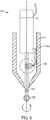
- the force sensor may be integrated directly in the surgical drill bit as illustrated in FIG. 6 .
- the force sensor 604 may be similarly integrated in other surgical instruments. Integrating the force sensor 604 in a surgical instrument, such as a drill bit 602, may be more robust as it minimizes the impact of external disturbances for measuring forces applied to the drill bit.
- the force sensor 604 is integrated in the shaft of the drill bit 602.
- the force sensor 604 in some implementations, is located on the drill bit 602 outside of the body 610 of the drill as shown in FIG. 6 . In other implementations, the force sensor 604 is located inside the body 610 of the drill, thereby better protecting the force sensor 604 from external influences. Force sensor can have multiple degrees of freedom and measure, for example, 1 to 3 forces and/or 1 to 3 torques. Forces are transmitted from the rotating shaft through a connector 606.
- the connector in some implementations, is one or more brushes that provide an electrical connection to the force sensor 604. If the force sensor is an optical sensor, the connector may be an optical transmitter (e.g.
- the brushes contact the drill bit thereby forming an electrical connection with the force sensor 604.
- the brushes touch one or more contacts on the drill bit to form the electrical connection.
- An electric or pneumatic motor 608 rotates the drill bit 602 shaft.
- a sensor 612 e.g., an encoder
- the sensor 612 measures position of the shaft.
- the sensor 612 measures the position of the shaft in order to correlate forces measured by the force sensor to the relative position of the shaft. For example, if the force sensor is located in a drill bit, the measurement of the direction of the force will vary as the drill bit rotates. Specifically, the force sensor measures force and the direction of the force periodically (e.g., every millisecond, every microsecond, or somewhere therebetween).
- the drill bit rotates as the surgeon pushes it into bone. When the drill contacts the bone, the force sensor will indicate some force (F1) in a direction (D1).
- the drill bit will rotate slightly so the force sensor will indicate force of the same value (F1) (assuming a constant force is applied) in a different direction (D2).
- the direction of the force will continue to change relative to a single perspective as the drill bit rotates even if surgeon pushes into the bone with a constant force.
- a constantly changing force direction is not acceptable.
- the positions of the drill in the global space must be calculated as the drill bit rotates.
- the sensor 612 is used to measure the position of the shaft and thus determine the global direction of the force (D).
- the sensor 612 may be located on the back of the motor 608 as shown in FIG. 6 .
- the sensor 612 may be located in other locations relative to the motor 608 as well.
- the force sensor 604 may be provided in various configurations as shown in FIGS. 7A-D . In each configuration, the goal is to measure forces on the tip of the tool (e.g., drill bit ultrasound bit, etc.). In the example shown in FIG. 7A the force sensor 604 is integrated in the shaft of the drill bit 602 as described in relation to FIG. 6 . The force sensor 604 may communicate with a connector 606 (shown in FIG. 6 ) via a sensor cable 702. The sensor cable 702, in some implementations, is routed inside the drill bit 602. In some implementations, the connector 606 (shown in FIG. 6 ) is electrically connected to the sensor cable 702 via one or more connection pads.
- the connector 606 shown in FIG. 6
- the connector 606 is electrically connected to the sensor cable 702 via one or more connection pads.
- the force sensor 604 in this example may be a miniaturized industrial sensor (e.g., the multi-axis force/torque sensor from ATI Industrial Automation, Inc. of Apex, NC) that measures, for example, all six components of force and torque using a transducer.
- the force sensor 604 may be an optical sensor.
- the force sensor 604 may comprise a strain gauge 706 integrated directly into the shaft of the drill bit 602 as shown in FIG. 7B .
- the force sensor 604 measures forces on the motor instead of measuring forces on the drill bit 602 itself.
- the shaft of the drill bit 602 in some implementations, includes a flexible element 708 that allows the drill bit 602 to bend (e.g., only slightly) such that after deflection of the shaft of the drill bit 602, forces can be measured by the force sensor 604.
- the measurement of shaft positions e.g., by sensor 612 as shown in FIG. 6
- the tool holder 408 as shown in FIG. 4 may have different implementations.
- the tool holder 408 is a flange that a surgical instrument tool may be secured to via, for example, bolts.
- the tool holder includes a rapid connection mechanism allowing for quick interchange of surgical instruments. In particular it may allow for attaching different surgical instruments/guides necessary for pedicle screw placement as described in U.S. Patent Application No. US2015/0100066, filed April 30, 2014 , and entitled "Apparatus, Systems, and Methods for Precise Guidance of Surgical Tool" and U.S. Patent Application No.
- US2015/0196365 filed January 15, 2015 , and entitled “Notched Apparatus for Guidance of an Insertable Instrument Along an Axis During Spinal Surgery”.
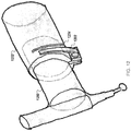
- An example implementation of the tool holder with a rapid connection mechanism is shown in Fig. 8 .
- the tool holder 802 has similar form to the one described in U.S. Patent Application No. US2015/0196365, filed January 15, 2015 , and entitled “Notched Apparatus for Guidance of an Insertable Instrument Along an Axis During Spinal Surgery”.
- the tubular structure of the tool holder 802 in some implementations, has one or more flanges that are configured for secure coupling of the holder 802 to an end effector of the robotic surgical system.
- the tubular structure defines an axis along which movement of a surgical instrument (fitted with a tool support) sliding through the structure is restricted.
- the tubular structure is configured (e.g., an interior surface of the structure is shaped and sized) to permit a tool support to slide through the holder 802 such that movement of the tool support is constrained to move along the axis (e.g., constrained in all directions except along the axis) defined by the holder 802.
- the surgical instrument 816 can be locked in place using a lock 804. This allows the surgical instrument 816 to be rigidly fixed to the robotic surgical system.
- the tool holder 802 has a longitudal notch 806 which is interfaced with peg 808.
- the peg 808 is a single pin as shown in FIG. 8 .
- the peg 808 supports a navigation tracker such the navigation marker is viewable by a navigation camera along an entire range of movement of the tool support through the holder 802.
- the navigation marker may be used by navigation camera to track the surgical instrument.
- the navigation marker may be, for example, navigation tracker such as the Dedicated NavLockTM tracker from Medtronic, Inc. of Minneapolis, MN.
- the intra-operative imaging system (not shown) may be, for example, the O-Arm from Medtronic, Inc. of Minneapolis, MN, the Airo from Mobius Imaging of Ayer, MA, or the BodyTom® from Neurologica Corp. of Danvers, MA.
- the longitudinal notch 806 is sized in relation to a peg 808.
- the surgical drill 816 has a sliding surface on the tool support 814 which interface with internal diameter of the holder 802. Sliding surface slides along the interior surface of the holder 802 and permits the tool 816 to slide into the holder such that movement of the tool 816 is constrained in all directions except along the axis defined by the holder 802.
- the sliding surface 814 is designed in order to slide into the holder 802 allowing the surgeon to achieve a linear motion of the instrument along the holder's 802 axis such that the tool 816 is fixedly attached to the robotic surgical system when fully inserted into the tool holder 802 and the lock 804 is engaged.
- the sliding surface 814 comprises more than one interface band.
- Connectors 810 and 812 can be used to transmit power to the drill 816 and for transmitting information, such as forces measured by a force sensor as described above, between the instrument and the robotic surgical system.
- the connectors 810 and 812 in some implementations, are positioned such that when the drill 816 is slide completely into the holder 802 the connectors 810 and 812 are electrically engaged.
- fixation has high rigidity
- fixation of the instrument shall be done without the need of additional tools
- the external part of the robot-side fixation (flange) shall be easy to clean
- the instrument-side of the fixation shall be sterilizable in an autoclave.
- the instrument e.g., drill
- the instrument can be secured to the robot using a bolt and pin based fixation system, such as the system described in U.S. Patent Application US2015/0305817, filed April 24, 2015 , entitled "Surgical Instrument Holder for Use with a Robotic Surgical System".
- a bolt and pin based fixation system such as the system described in U.S. Patent Application US2015/0305817, filed April 24, 2015 , entitled "Surgical Instrument Holder for Use with a Robotic Surgical System".
- the instrument holder base 1012 in U.S. Patent Application No. US2015/0305817 is integrated into the surgical drill.
- the drill can slide onto a protruding bolt and be secured by a nut, similar to the instrument holder base described in U.S. Patent Application No. US2015/0305817 .
- FIGS. 11A through 11F illustrate an example lever system for securing an instrument to a robot.
- Robot flange 1152 is fixed to the robot. It contains the lever system 1102 used to generate fixation force through the lever 1102a.
- Instrument 1150 is shown as a surgical instrument holder, such as that described in U.S. Patent Application No. US2015/0305817 . However, this can be adapted to other instruments, such as a surgical drill.
- FIG. 11C shows the lever system in more detail. It includes a lever system 1102 (including components 1102a, 1102b, 1102c, and 1102d), quick lock mechanism 1104 (including components 1104a and 1104b) and positioning pins 1106 (including 1106a, 1106b, and 1106c).
- the lever system 1102 is used to generate high forces. User pushes the lever 1102a in the direction of the arrow. Thanks to the level ratio the forces are increased and transmitted through the intermediate elements (1102b, 1102c, and 1102d) to the rod (1102e). On the rod, the quick lock mechanism 1104 is mounted.
- the guide plate 1108 allows the pin head 1104b to pass therethrough and also allows the positioning pins 1106 (such as those described in U.S. Patent Application No. US2015/0305817 ) to interface with the guide plate 1108 to ensure proper alignment of the instrument 1150.
- the quick lock mechanism pulls the surgical instrument tight against the flange 1152.
- the locked position of the mechanism is shown in FIGS. 11B and 11D .
- joint 1120e is on the left side of the line L going through the joints 1120a and 1120c. Thanks to this configuration, a bi-stable behavior is achieved and the lever remains closed until being slightly raised. In this configuration very high forces are achieved because of alignment of intermediate elements 1102c and 1102d (illustrated by the bold line L). This configuration is called a toggle mechanism.
- the lever system 1102 is activated by being pushed in the direction of the arrow, element 1102b rotates around pin 1120b, lever 1102a rotates about pin 1120a, element 1102c rotates about pin 1120c, and pin 1120d connects elements 1102b, 1102c, and 1102c.
- the quick lock hook 1104a can be released (e.g., by pressing tab 1124 directly or indirectly be a separate lever or button) such that the instrument 1150 can be removed.
- the linkage is arranged such that the bold line L is straight.
- FIG. 12 illustrates an example system for securing an instrument to a robot.
- FIG. 12 illustrates a friction based system.
- the instrument 1250 is blocked in robot flange 1252 due to the friction between the two parts.
- the force is applied by the lever 1202 and thanks to the material compliance achieved by adding a notch (grey) the instrument part is tightly blocked inside. It is similar mechanism to the one known in bicycles seats.
- FIG. 13 illustrates an example system for securing an instrument to a robot.
- a shape lock system is used to secure the instrument to the robot.
- Shape locks can be achieved between two elements having specific forms.
- An example is a Bayonet mount shown in this example.
- the robot flange 1352 includes a pair of shape lock cutouts 1354a and 1354b (two cutouts are shown here, however, more cutouts may be used, such as 4, 5, or 6 cutouts) and the instrument 1350 includes a pair of protrusions 1356 (only one is shown in this illustration).
- the protrusions 1356 engage the cutouts 1354a and 1354b when the instrument 1350 slides into the flange 1352.
- the instrument 1350 can be twisted such that is it locked to the flange 1352 by the protrusions 1356 and the cutouts 1354a and 1354b
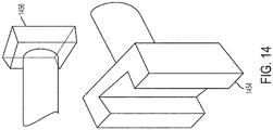
- FIG. 14 illustrates an example system for securing an instrument to a robot.
- Linear guides such as guide 1454, can be used to lock the instrument in the robot flange.
- a spring or other device can be used to remove any mechanical backlash such that the instrument cannot be removed after being inserted into the guide until the spring or other mechanism is released.
- a corresponding member 1456 is attached to the instrument and engages the guide 1454 which is attached to the robot flange.
- a method of performing surgery Initially, an incision is made and the vertebra is exposed. In some implementations, the frame of the navigation system is attached to the patient in the place selected by the surgeon. Intra-operative medical images of the target anatomy may be obtained. Alternatively, images are acquired pre-operatively.
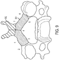
- FIG. 9 is an illustration of volumetric planning.
- volumetric planning is linked with registration precision improvement algorithms.
- the surgeon may use the navigation system pointer to measure points or follow a path traced by the surgeon using the pointer, thereby generating a set of points that identify (e.g., outline) the volume to be removed.
- the surgeon uses robot end effector in force control mode (e.g., as described in U.S. Patent Application No. US2015/0100066, filed April 30, 2014 , and entitled "Apparatus, Systems, and Methods for Precise Guidance of Surgical Tool", to identify the points (e.g., the points identifying the volume to be removed).
- the position of the robot end effector may be tracked by the navigation system using a navigation marker fixed in relation to the surgical instrument Additionally, the volume can be identified using automatic segmentation, semi-automatic segmentation (e.g., using surgeon-defined points or corrections), or fully manual when surgeon/assistant/neurologist defines volume by manually selecting etc. the "pixels"/"voxels" to be removed.
- a surgeon first removes the spinous process 902 using, for example, pliers and cutting along the red zigzag line as shown in FIG. 9 .
- the surgeon identifies the extremities of the volume to be removed (shown in blue and labeled as 904.
- the surgeon can do this by using a navigation pointer and pointing to separate points (e.g. points (1), (2), (3), (4), (5), (6), and (7)) on the patient anatomy or, alternatively, the navigation system may follow a path identified by the surgeon and automatically collect of points.
- the system generates the volume to be removed by taking a set of points (e.g., identified by the surgeon) and/or patient volumetric information (e.g., medical images) and identifying parts of the vertebrae to be removed.
- the system in some implementations, combines the points identified by the surgeon and the patient volumetric information to identify the volume to be removed.
- the system utilizes medical image segmentation (e.g., statistical shape modeling) to identify the volume.
- the navigation system may track the points identified by the surgeon and medical images on the navigation screen, in some implementations, are automatically updated to show feedback about the planning. This can be achieved, for example, using different colors on several views of medical images (e.g., the blue section shown in FIG. 9 ).
- the planning algorithms recognize which part of the spinous process was removed. In some implementations, this is achieved if the surgeon shows a point on the patient anatomy which normally should be inside bone. If surgeon is able to point there, it demonstrates that this part of the bone was removed and it should be tagged and shown on a display (e.g., using different color such as red as shown in FIG. 9 ).
- the precision is crucial.
- the relative positions of the vertebrae may change due to forces applied by the surgeon.
- precision points e.g. points (1), (2), (3), (4), (5), (6), and (7)
- a path may be followed to collect a plurality of points that identify the volume to be removed.
- points identified by the surgeon and the patient volumetric information e.g., medical images
- the combination of the points identified by the surgeon and the patient volumetric information allows for a more precise mapping of the volume to be removed.
- these points are collected using the robot in manual or lose control as described in relation to FIG. 9 .
- the force sensor can be used to automatically detect bone versus tissue, something that is difficult to do manually.
- automatic and semi-automatic segmentation algorithms for use van be used to plan a volume to be removed as well as other surgeries.
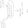
- FIG. 15 is an illustration of an example method for volume definition.
- Object characterization as shown in FIG. 15 defines the object to be removed.
- the characterization can be identified spatially, such as set of points delimiting the volume to be removed, or by identifying the type of surgery or volume to remove, e.g. spinous process, lamina, etc.
- the object characterization can be the set of points identified by the surgeon (e.g., using a pointer) to delineate the area to remove (or operate on in another example), the operation being performed, the specific area to be removed (e.g., identification of a specific portion of the body (e.g., lamina of c7 vertebrae), or a set of the above.
- Patient images as shown in FIG. 15 represents the set of images for which the actual volume definition should apply. These images can be CT, MRI, X-ray and/or fluoroscopy images.
- the segmentation algorithm takes the object characterization and patient images as an input and gives on the output an exact volume definition which in objective, measurable terms specifying the volume to be removed (e.g. series of spatial coordinates, volume mesh, voxel data etc.).
- the object characterization is not an input into the algorithm.
- the patient images and the specific area to be removed e.g., identification of a specific portion of the body (e.g., lamina of c7 vertebrae) can be the input to the algorithm and the algorithm can determine the area to be removed.
- the area identified for removal by the algorithm is displayed back to the user (e.g., via a display on the robot) for confirmation by the surgeon.
- Atlas based segmentation e.g. Expectation-Maximization algorithm or Statistical Shape Modelling algorithm.
- SSM Statistical Shape Modelling
- a segmentation algorithm kernel e.g. Gaussian kernel or multi-scale Gaussian kernel, transforms the atlas to fulfill the constraints of the object definition and patient images.
- a volume definition is obtained and can be reused in further algorithm steps.
- the robot can be automatically brought to the volume or a surgeon may move the robot to the arm using the hands-on control mode as described in U.S. Patent Application No. US2015/0100066, filed April 30, 2014 , and entitled "Apparatus, Systems, and Methods for Precise Guidance of Surgical Tool”.
- the planned volume may be removed using robotic assistance in several ways. In some implementations, the volume may be removed based on stay-in/no-go zones as described in U.S. Patent Application No. US2014/0121676, filed April, 2, 2012 , and entitled "Robotic System and Method for Spinal and Other Surgeries".
- the removing tool stays blocked inside virtual volume (constrained movement) as long as it is not completely removed or the surgeon voluntarily wants to quit the volume.
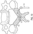
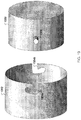
- FIG. 10 An alternative approach for removing the appropriate volume is shown in FIG. 10 .
- the robot automatically moves the drilling/milling/erasing instrument 1002 in a type of "painting" trajectory while being supervised by the surgeon. It is important to indicate to user the volume that has be removed 1004 and remaining volume 1006. This may be shown on a display of the robot or on a display separate from the robot.
- a surgeon can supervise the robot by looking at the actual position on the navigation screen.
- the surgeon can stop the robot movement at any time, for example, if the surgeon is concerned about the position of the removal instrument.
- a dead-man switch is used.
- the switch may be activated if the surgeon places his/her hands on the tool holder interface or if the surgeon removes his/her hands from the tool holder interface.
- presence detection switches may be used and/or voice recognition may be used to recognize gestures and voice commands, respectively.
- a force sensor signal can be used to detect if the surgical instrument goes across the edge of the vertebra and, in response, the robotic surgical system can prevent movement of the surgical instrument and destruction of surrounding tissue. This is achieved, for example, using edge detection algorithms which use relative changes in force. Additionally, in some implementations, neuro-monitoring may be used for detection of nervous system infraction.
- the robot may be used to partially remove the target volume, thereby leaving the most difficult and less laborious parts of the tissue to be removed manually by the surgeon.
- the amount of the target volume removed by the robot is controlled during the volume planning phase.
- the robot After the robot finishes removing the target volume (e.g., the entire volume or a portion of the volume), the robot is moved away from the patient. In some implementations, this is done automatically by the robot itself. In other implementations, the robotic end effect is manually moved using the hands-on control mode. In some implementations, after moving the robot away the surgeon may inspect the removal of the volume by the robot and/or complete the surgery manually.
- the target volume e.g., the entire volume or a portion of the volume
- the robot is moved away from the patient. In some implementations, this is done automatically by the robot itself. In other implementations, the robotic end effect is manually moved using the hands-on control mode. In some implementations, after moving the robot away the surgeon may inspect the removal of the volume by the robot and/or complete the surgery manually.
- the cloud computing environment 1600 may include one or more resource providers 1602a, 1602b, 1602c (collectively, 1602).
- Each resource provider 1602 may include computing resources.
- computing resources may include any hardware and/or software used to process data.
- computing resources may include hardware and/or software capable of executing algorithms, computer programs, and/or computer applications.
- exemplary computing resources may include application servers and/or databases with storage and retrieval capabilities.
- Each resource provider 1602 may be connected to any other resource provider 1602 in the cloud computing environment 1600.
- the resource providers 1602 may be connected over a computer network 1608.
- Each resource provider 1602 may be connected to one or more computing device 1604a, 1604b, 1604c (collectively, 1604), over the computer network 1608.
- the cloud computing environment 1600 may include a resource manager 1606.
- the resource manager 1606 may be connected to the resource providers 1602 and the computing devices 1604 over the computer network 1608.
- the resource manager 1606 may facilitate the provision of computing resources by one or more resource providers 1602 to one or more computing devices 1604.
- the resource manager 1606 may receive a request for a computing resource from a particular computing device 1604.
- the resource manager 1606 may identify one or more resource providers 1602 capable of providing the computing resource requested by the computing device 1604.
- the resource manager 1606 may select a resource provider 1602 to provide the computing resource.
- the resource manager 1606 may facilitate a connection between the resource provider 1602 and a particular computing device 1604.
- the resource manager 1606 may establish a connection between a particular resource provider 1602 and a particular computing device 1604. In some implementations, the resource manager 1606 may redirect a particular computing device 1604 to a particular resource provider 1602 with the requested computing resource.
- FIG. 17 shows an example of a computing device 1700 and a mobile computing device 1750 that can be used to implement the techniques described in this disclosure.
- the computing device 1700 is intended to represent various forms of digital computers, such as laptops, desktops, workstations, personal digital assistants, servers, blade servers, mainframes, and other appropriate computers.
- the mobile computing device 1750 is intended to represent various forms of mobile devices, such as personal digital assistants, cellular telephones, smart-phones, and other similar computing devices.
- the components shown here, their connections and relationships, and their functions, are meant to be examples only, and are not meant to be limiting.
- the computing device 1700 includes a processor 1702, a memory 1704, a storage device 1706, a high-speed interface 1708 connecting to the memory 1704 and multiple high-speed expansion ports 1710, and a low-speed interface 1712 connecting to a low-speed expansion port 1714 and the storage device 1706.
- Each of the processor 1702, the memory 1704, the storage device 1706, the high-speed interface 1708, the high-speed expansion ports 1710, and the low-speed interface 1712 are interconnected using various busses, and may be mounted on a common motherboard or in other manners as appropriate.
- the processor 1702 can process instructions for execution within the computing device 1700, including instructions stored in the memory 1704 or on the storage device 1706 to display graphical information for a GUI on an external input/output device, such as a display 1716 coupled to the high-speed interface 1708.
- an external input/output device such as a display 1716 coupled to the high-speed interface 1708.
- multiple processors and/or multiple buses may be used, as appropriate, along with multiple memories and types of memory.
- multiple computing devices may be connected, with each device providing portions of the necessary operations (e.g., as a server bank, a group of blade servers, or a multi-processor system).
- the memory 1704 stores information within the computing device 1700.
- the memory 1704 is a volatile memory unit or units.
- the memory 1704 is a non-volatile memory unit or units.
- the memory 1704 may also be another form of computer-readable medium, such as a magnetic or optical disk.
- the storage device 1706 is capable of providing mass storage for the computing device 1700.
- the storage device 1706 may be or contain a computer-readable medium, such as a floppy disk device, a hard disk device, an optical disk device, or a tape device, a flash memory or other similar solid state memory device, or an array of devices, including devices in a storage area network or other configurations.
- Instructions can be stored in an information carrier.
- the instructions when executed by one or more processing devices (for example, processor 1702), perform one or more methods, such as those described above.
- the instructions can also be stored by one or more storage devices such as computer- or machine-readable mediums (for example, the memory 1704, the storage device 1706, or memory on the processor 1702).
- the high-speed interface 1708 manages bandwidth-intensive operations for the computing device 1700, while the low-speed interface 1712 manages lower bandwidth-intensive operations. Such allocation of functions is an example only.
- the high-speed interface 1708 is coupled to the memory 1704, the display 1716 (e.g., through a graphics processor or accelerator), and to the high-speed expansion ports 1710, which may accept various expansion cards (not shown).
- the low-speed interface 1712 is coupled to the storage device 1706 and the low-speed expansion port 1714.
- the low-speed expansion port 1714 which may include various communication ports (e.g., USB, Bluetooth®, Ethernet, wireless Ethernet) may be coupled to one or more input/output devices, such as a keyboard, a pointing device, a scanner, or a networking device such as a switch or router, e.g., through a network adapter.
- input/output devices such as a keyboard, a pointing device, a scanner, or a networking device such as a switch or router, e.g., through a network adapter.
- the computing device 1700 may be implemented in a number of different forms, as shown in the figure. For example, it may be implemented as a standard server 1720, or multiple times in a group of such servers. In addition, it may be implemented in a personal computer such as a laptop computer 1722. It may also be implemented as part of a rack server system 1724. Alternatively, components from the computing device 1700 may be combined with other components in a mobile device (not shown), such as a mobile computing device 1750. Each of such devices may contain one or more of the computing device 1700 and the mobile computing device 1750, and an entire system may be made up of multiple computing devices communicating with each other.
- the mobile computing device 1750 includes a processor 1752, a memory 1764, an input/output device such as a display 1754, a communication interface 1766, and a transceiver 1768, among other components.
- the mobile computing device 1750 may also be provided with a storage device, such as a micro-drive or other device, to provide additional storage.
- a storage device such as a micro-drive or other device, to provide additional storage.
- Each of the processor 1752, the memory 1764, the display 1754, the communication interface 1766, and the transceiver 1768, are interconnected using various buses, and several of the components may be mounted on a common motherboard or in other manners as appropriate.
- the processor 1752 can execute instructions within the mobile computing device 1750, including instructions stored in the memory 1764.
- the processor 1752 may be implemented as a chipset of chips that include separate and multiple analog and digital processors.
- the processor 1752 may provide, for example, for coordination of the other components of the mobile computing device 1750, such as control of user interfaces, applications run by the mobile computing device 1750, and wireless communication by the mobile computing device 1750.
- the processor 1752 may communicate with a user through a control interface 1758 and a display interface 1756 coupled to the display 1754.
- the display 1754 may be, for example, a TFT (Thin-Film-Transistor Liquid Crystal Display) display or an OLED (Organic Light Emitting Diode) display, or other appropriate display technology.
- the display interface 1756 may comprise appropriate circuitry for driving the display 1754 to present graphical and other information to a user.
- the control interface 1758 may receive commands from a user and convert them for submission to the processor 1752.
- an external interface 1762 may provide communication with the processor 1752, so as to enable near area communication of the mobile computing device 1750 with other devices.
- the external interface 1762 may provide, for example, for wired communication in some implementations, or for wireless communication in other implementations, and multiple interfaces may also be used.
- the memory 1764 stores information within the mobile computing device 1750.
- the memory 1764 can be implemented as one or more of a computer-readable medium or media, a volatile memory unit or units, or a non-volatile memory unit or units.
- An expansion memory 1774 may also be provided and connected to the mobile computing device 1750 through an expansion interface 1772, which may include, for example, a SIMM (Single In Line Memory Module) card interface.
- SIMM Single In Line Memory Module
- the expansion memory 1774 may provide extra storage space for the mobile computing device 1750, or may also store applications or other information for the mobile computing device 1750.
- the expansion memory 1774 may include instructions to carry out or supplement the processes described above, and may include secure information also.
- the expansion memory 1774 may be provide as a security module for the mobile computing device 1750, and may be programmed with instructions that permit secure use of the mobile computing device 1750.
- secure applications may be provided via the SIMM cards, along with additional information, such as placing identifying information on the SIMM card in a non-hackable manner.
- the memory may include, for example, flash memory and/or NVRAM memory (non-volatile random access memory), as discussed below.
- instructions are stored in an information carrier. that the instructions, when executed by one or more processing devices (for example, processor 1752), perform one or more methods, such as those described above.
- the instructions can also be stored by one or more storage devices, such as one or more computer- or machine-readable mediums (for example, the memory 1764, the expansion memory 1774, or memory on the processor 1752).
- the instructions can be received in a propagated signal, for example, over the transceiver 1768 or the external interface 1762.
- the mobile computing device 1750 may communicate wirelessly through the communication interface 1766, which may include digital signal processing circuitry where necessary.
- the communication interface 1766 may provide for communications under various modes or protocols, such as GSM voice calls (Global System for Mobile communications), SMS (Short Message Service), EMS (Enhanced Messaging Service), or MMS messaging (Multimedia Messaging Service), CDMA (code division multiple access), TDMA (time division multiple access), PDC (Personal Digital Cellular), WCDMA (Wideband Code Division Multiple Access), CDMA2000, or GPRS (General Packet Radio Service), among others.
- GSM voice calls Global System for Mobile communications
- SMS Short Message Service
- EMS Enhanced Messaging Service
- MMS messaging Multimedia Messaging Service
- CDMA code division multiple access
- TDMA time division multiple access
- PDC Personal Digital Cellular
- WCDMA Wideband Code Division Multiple Access
- CDMA2000 Code Division Multiple Access
- GPRS General Packet Radio Service
- a GPS (Global Positioning System) receiver module 1770 may provide additional navigation- and location-related wireless data to the mobile computing device 1750, which may be used as appropriate by applications running on the mobile computing device 1750.
- the mobile computing device 1750 may also communicate audibly using an audio codec 1760, which may receive spoken information from a user and convert it to usable digital information.
- the audio codec 1760 may likewise generate audible sound for a user, such as through a speaker, e.g., in a handset of the mobile computing device 1750.
- Such sound may include sound from voice telephone calls, may include recorded sound (e.g., voice messages, music files, etc.) and may also include sound generated by applications operating on the mobile computing device 1750.
- the mobile computing device 1750 may be implemented in a number of different forms, as shown in the figure. For example, it may be implemented as a cellular telephone 1780. It may also be implemented as part of a smart-phone 1782, personal digital assistant, or other similar mobile device.
- implementations of the systems and techniques described here can be realized in digital electronic circuitry, integrated circuitry, specially designed ASICs (application specific integrated circuits), computer hardware, firmware, software, and/or combinations thereof.
- ASICs application specific integrated circuits
- These various implementations can include implementation in one or more computer programs that are executable and/or interpretable on a programmable system including at least one programmable processor, which may be special or general purpose, coupled to receive data and instructions from, and to transmit data and instructions to, a storage system, at least one input device, and at least one output device.
- machine-readable medium and computer-readable medium refer to any computer program product, apparatus and/or device (e.g., magnetic discs, optical disks, memory, Programmable Logic Devices (PLDs)) used to provide machine instructions and/or data to a programmable processor, including a machine-readable medium that receives machine instructions as a machine-readable signal.
- machine-readable signal refers to any signal used to provide machine instructions and/or data to a programmable processor.
- the systems and techniques described here can be implemented on a computer having a display device (e.g., a CRT (cathode ray tube) or LCD (liquid crystal display) monitor) for displaying information to the user and a keyboard and a pointing device (e.g., a mouse or a trackball) by which the user can provide input to the computer.
- a display device e.g., a CRT (cathode ray tube) or LCD (liquid crystal display) monitor
- a keyboard and a pointing device e.g., a mouse or a trackball
- Other kinds of devices can be used to provide for interaction with a user as well; for example, feedback provided to the user can be any form of sensory feedback (e.g., visual feedback, auditory feedback, or tactile feedback); and input from the user can be received in any form, including acoustic, speech, or tactile input.
Claims (15)
- Support d'instrument chirurgical utilisé avec un système chirurgical robotique, le support d'instrument chirurgical comprenant :une structure tubulaire creuse rigide dotée d'une extrémité ouverte proximale et d'une extrémité ouverte distale, ladite structure définissant un axe le long duquel le mouvement d'un instrument chirurgical coulissant à travers la structure est restreint, la structure tubulaire ayant une surface intérieure formée et dimensionnée pour loger l'instrument chirurgical coulissant à travers le support d'instrument chirurgical de sorte que le mouvement de l'instrument chirurgical soit contraint de se déplacer le long de l'axe défini par le support d'instrument chirurgical ; etun élément connecteur, attaché au support, qui, quand il est engagé avec un élément connecteur correspondant associé à un instrument chirurgical, fournit de l'électricité à l'instrument chirurgical, caractérisé en ce que la structure tubulaire comprend une encoche longitudinale le long de sa longueur, l'encoche longitudinale étant dimensionnée en lien avec un taquet situé sur l'instrument chirurgical pour permettre à l'instrument chirurgical de coulisser le long de l'axe défini par le support d'instrument chirurgical.
- Support d'instrument chirurgical selon la revendication 1, dans lequel la structure tubulaire a une surface extérieure comprenant au moins une bride qui est dimensionnée et formée pour assurer l'accouplement du support d'instrument chirurgical à un effecteur d'extrémité du système chirurgical robotique.
- Support d'instrument chirurgical selon la revendication 1 ou la revendication 2, comprenant un verrou qui, quand il est engagé, limite le mouvement d'un instrument chirurgical à l'intérieur de la structure tubulaire creuse rigide.
- Support d'instrument chirurgical selon la revendication 3, dans lequel le verrou, quand il est engagé, empêche le retrait de l'instrument chirurgical du support d'instrument chirurgical.
- Support d'instrument chirurgical selon l'une quelconque des revendications précédentes, comprenant un capteur de force qui mesure au moins une force et/ou un couple appliqué à au moins une partie de l'instrument chirurgical.
- Support d'instrument chirurgical selon l'une quelconque des revendications précédentes, dans lequel :le support d'instrument chirurgical comprend un capteur de force qui mesure au moins une force et/ou un couple appliqué à au moins une partie de l'instrument chirurgical etles informations de mesure fournies au support d'instrument chirurgical par le biais du connecteur comprennent au moins une force et/ou un couple.
- Support d'instrument chirurgical selon l'une quelconque des revendications précédentes, le support d'instrument chirurgical étant conçu pour maintenir une fraise.
- Support d'instrument chirurgical selon l'une quelconque des revendications précédentes, le support d'instrument chirurgical étant conçu pour maintenir une fraise dotée d'une mèche de fraise.
- Support d'instrument chirurgical selon la revendication 8, dans lequel la partie de l'instrument chirurgical auquel l'au moins une force et/ou couple sont appliqués est la mèche de fraise.
- Support d'instrument chirurgical selon l'une quelconque des revendications précédentes, le support d'instrument chirurgical étant conçu pour maintenir un dispositif de meulage.
- Support d'instrument chirurgical selon l'une quelconque des revendications précédentes, le support d'instrument chirurgical étant conçu pour maintenir un rasoir électrique.
- Support d'instrument chirurgical selon l'une quelconque des revendications précédentes, le support d'instrument chirurgical étant conçu pour maintenir un laser.
- Support d'instrument chirurgical selon l'une quelconque des revendications précédentes, le support d'instrument chirurgical étant conçu pour maintenir un scalpel à ultrasonique.
- Support d'instrument chirurgical selon l'une quelconque des revendications précédentes, le support d'instrument chirurgical étant utilisé en chirurgie spinale.
- Support d'instrument chirurgical selon l'une quelconque des revendications précédentes, le support d'instrument chirurgical étant conçu pour maintenir un tournevis.
Applications Claiming Priority (2)
| Application Number | Priority Date | Filing Date | Title |
|---|---|---|---|
| US201462086677P | 2014-12-02 | 2014-12-02 | |
| PCT/EP2015/078398 WO2016087539A2 (fr) | 2014-12-02 | 2015-12-02 | Élimination de volume assistée par robot pendant une intervention chirurgicale |
Publications (2)
| Publication Number | Publication Date |
|---|---|
| EP3226781A2 EP3226781A2 (fr) | 2017-10-11 |
| EP3226781B1 true EP3226781B1 (fr) | 2018-08-01 |
Family
ID=55022419
Family Applications (1)
| Application Number | Title | Priority Date | Filing Date |
|---|---|---|---|
| EP15816096.0A Active EP3226781B1 (fr) | 2014-12-02 | 2015-12-02 | Élimination de volume assistée par robot pendant une intervention chirurgicale |
Country Status (4)
| Country | Link |
|---|---|
| US (2) | US11103316B2 (fr) |
| EP (1) | EP3226781B1 (fr) |
| JP (1) | JP6731920B2 (fr) |
| WO (1) | WO2016087539A2 (fr) |
Families Citing this family (85)
| Publication number | Priority date | Publication date | Assignee | Title |
|---|---|---|---|---|
| US9155544B2 (en) | 2002-03-20 | 2015-10-13 | P Tech, Llc | Robotic systems and methods |
| US10779957B2 (en) | 2010-09-03 | 2020-09-22 | Globus Medical, Inc. | Expandable fusion device and method of installation thereof |
| US11135026B2 (en) | 2012-05-11 | 2021-10-05 | Peter L. Bono | Robotic surgical system |
| US11298196B2 (en) | 2012-06-21 | 2022-04-12 | Globus Medical Inc. | Surgical robotic automation with tracking markers and controlled tool advancement |
| US11857266B2 (en) | 2012-06-21 | 2024-01-02 | Globus Medical, Inc. | System for a surveillance marker in robotic-assisted surgery |
| US10646280B2 (en) | 2012-06-21 | 2020-05-12 | Globus Medical, Inc. | System and method for surgical tool insertion using multiaxis force and moment feedback |
| US11253327B2 (en) | 2012-06-21 | 2022-02-22 | Globus Medical, Inc. | Systems and methods for automatically changing an end-effector on a surgical robot |
| US11857149B2 (en) | 2012-06-21 | 2024-01-02 | Globus Medical, Inc. | Surgical robotic systems with target trajectory deviation monitoring and related methods |
| US11045267B2 (en) | 2012-06-21 | 2021-06-29 | Globus Medical, Inc. | Surgical robotic automation with tracking markers |
| US11864745B2 (en) | 2012-06-21 | 2024-01-09 | Globus Medical, Inc. | Surgical robotic system with retractor |
| US11793570B2 (en) | 2012-06-21 | 2023-10-24 | Globus Medical Inc. | Surgical robotic automation with tracking markers |
| US11786324B2 (en) | 2012-06-21 | 2023-10-17 | Globus Medical, Inc. | Surgical robotic automation with tracking markers |
| US10842461B2 (en) | 2012-06-21 | 2020-11-24 | Globus Medical, Inc. | Systems and methods of checking registrations for surgical systems |
| US10799298B2 (en) | 2012-06-21 | 2020-10-13 | Globus Medical Inc. | Robotic fluoroscopic navigation |
| US11399900B2 (en) | 2012-06-21 | 2022-08-02 | Globus Medical, Inc. | Robotic systems providing co-registration using natural fiducials and related methods |
| US10874466B2 (en) | 2012-06-21 | 2020-12-29 | Globus Medical, Inc. | System and method for surgical tool insertion using multiaxis force and moment feedback |
| US11864839B2 (en) | 2012-06-21 | 2024-01-09 | Globus Medical Inc. | Methods of adjusting a virtual implant and related surgical navigation systems |
| US11589771B2 (en) * | 2012-06-21 | 2023-02-28 | Globus Medical Inc. | Method for recording probe movement and determining an extent of matter removed |
| US10758315B2 (en) | 2012-06-21 | 2020-09-01 | Globus Medical Inc. | Method and system for improving 2D-3D registration convergence |
| US10624710B2 (en) | 2012-06-21 | 2020-04-21 | Globus Medical, Inc. | System and method for measuring depth of instrumentation |
| US11317971B2 (en) | 2012-06-21 | 2022-05-03 | Globus Medical, Inc. | Systems and methods related to robotic guidance in surgery |
| WO2015107099A1 (fr) * | 2014-01-15 | 2015-07-23 | KB Medical SA | Appareil entaillé pour guider un instrument pouvant être introduit le long d'un axe pendant une chirurgie rachidienne |
| US10357257B2 (en) | 2014-07-14 | 2019-07-23 | KB Medical SA | Anti-skid surgical instrument for use in preparing holes in bone tissue |
| US10765438B2 (en) | 2014-07-14 | 2020-09-08 | KB Medical SA | Anti-skid surgical instrument for use in preparing holes in bone tissue |
| EP3258872B1 (fr) | 2015-02-18 | 2023-04-26 | KB Medical SA | Systèmes pour pratiquer des micromanipulations chirurgicales à la colonne vertébrale avec un système chirurgical robotique en utilisant une technique percutanée |
| WO2016160272A1 (fr) | 2015-03-27 | 2016-10-06 | Sonitrack Systems, Inc. | Bras de support alimenté rapidement repositionnable |
| US11883217B2 (en) | 2016-02-03 | 2024-01-30 | Globus Medical, Inc. | Portable medical imaging system and method |
| US10078333B1 (en) * | 2016-04-17 | 2018-09-18 | X Development Llc | Efficient mapping of robot environment |
| US11141229B2 (en) * | 2016-06-03 | 2021-10-12 | Rubicon Spine Llc | Dynamic feedback end effector |
| US10413371B2 (en) * | 2016-06-03 | 2019-09-17 | Rubicon Spine, LLC | Dynamic feedback end effector |
| GB2552540B (en) | 2016-07-29 | 2021-11-24 | Cmr Surgical Ltd | Interface structure |
| GB2600067B (en) * | 2016-07-29 | 2022-08-10 | Cmr Surgical Ltd | Motion feedthrough |
| US11925431B2 (en) | 2016-07-29 | 2024-03-12 | Cmr Surgical Limited | Motion feedthrough |
| CN110062608B (zh) * | 2016-11-11 | 2023-04-25 | 直观外科手术操作公司 | 带有基于扫描的定位的远程操作手术系统 |
| US10568706B2 (en) | 2016-12-15 | 2020-02-25 | Ethicon Llc | Trocar Simulation |
| JP7063629B2 (ja) * | 2017-01-13 | 2022-05-09 | ケービー メディカル エスアー | 骨組織に穴を準備する滑り止め付き手術用器具 |
| JP7233841B2 (ja) | 2017-01-18 | 2023-03-07 | ケービー メディカル エスアー | ロボット外科手術システムのロボットナビゲーション |
| GB2552855B (en) * | 2017-01-31 | 2019-02-13 | Cmr Surgical Ltd | Surgical instrument engagement detection |
| US11071594B2 (en) * | 2017-03-16 | 2021-07-27 | KB Medical SA | Robotic navigation of robotic surgical systems |
| US10349986B2 (en) | 2017-04-20 | 2019-07-16 | Warsaw Orthopedic, Inc. | Spinal implant system and method |
| AU2018263972B2 (en) * | 2017-05-03 | 2021-06-17 | Lsi Solutions, Inc. | Surgical equipment holder |
| WO2018209042A2 (fr) | 2017-05-10 | 2018-11-15 | Mako Surgical Corp. | Système et méthodes robotiques d'opération chirurgicale de la colonne vertébrale |
| US11033341B2 (en) | 2017-05-10 | 2021-06-15 | Mako Surgical Corp. | Robotic spine surgery system and methods |
| EP3431025B1 (fr) * | 2017-07-18 | 2023-06-21 | Globus Medical, Inc. | Système d'insertion d'un outil chirurgical au moyen d'une force multiaxiale et d'une rétroaction de moment |
| AU2018355215A1 (en) | 2017-10-23 | 2020-06-11 | Capstone Surgical Technologies, Llc | Rotary oscillating and linearly reciprocating surgical tool |
| US10987175B2 (en) | 2017-12-06 | 2021-04-27 | Medtech S.A. | Robotic shoulder repair and reconstruction |
| NL2020243B1 (en) * | 2018-01-08 | 2019-07-15 | Slam Ortho B V | A system and a drill bit for drilling a bore in a bone and measuring a depth of the bore during surgery |
| CA3088304A1 (fr) | 2018-01-12 | 2019-07-18 | Peter L. BONO | Systeme de commande chirurgical robotise |
| CA3088311A1 (fr) * | 2018-01-12 | 2019-07-18 | Peter L. BONO | Systeme d'ancrage de capteur chirurgical |
| EP3743004A1 (fr) | 2018-01-26 | 2020-12-02 | Mako Surgical Corp. | Effecteurs terminaux, systèmes et procédés d'impact de prothèses guidées par des robots chirurgicaux |
| US10687792B2 (en) | 2018-03-12 | 2020-06-23 | Zimmer Biomet CMF and Thoracic, LLC | End effector coupler for surgical arm |
| US10772704B2 (en) | 2018-03-12 | 2020-09-15 | Zimmer Biomet CMF and Thoracic, LLC | End effector coupler for surgical arm |
| WO2019177569A1 (fr) * | 2018-03-12 | 2019-09-19 | Zimmer Biomet CMF and Thoracic, LLC | Dispositif d'accouplement d'effecteur terminal pour bras chirurgical |
| US10835345B2 (en) | 2018-03-12 | 2020-11-17 | Zimmer Biomet CMF and Thoracic, LLC | End effector coupler for surgical arm |
| USD878585S1 (en) | 2018-03-12 | 2020-03-17 | Zimmer Biomet CMF and Thoracic, LLC | End effector coupler stem |
| CN112236098A (zh) * | 2018-04-12 | 2021-01-15 | 埃因霍温医疗机器人有限公司 | 用于去除骨头的机器人器械 |
| US10746525B2 (en) * | 2018-04-20 | 2020-08-18 | The Boeing Company | Capacitive-sensing paint borer |
| US11103256B2 (en) * | 2018-05-21 | 2021-08-31 | Acclarent, Inc. | Shaver with blood vessel and nerve monitoring features |
| CN108652591A (zh) * | 2018-05-22 | 2018-10-16 | 张清娟 | 一种耳鼻喉辅助护理检查仪 |
| EP3574853B1 (fr) * | 2018-05-28 | 2020-12-02 | DePuy Ireland Unlimited Company | Système robotique pour enlever de la matière osseuse d'une structure anatomique |
| CA3104435A1 (fr) * | 2018-06-22 | 2019-12-26 | Universitat Basel | Dispositif de detection de force, endodispositif medical et methode d'utilisation d'un tel endodispositif |
| US20210315591A1 (en) * | 2018-07-23 | 2021-10-14 | Universiteit Gent | Bone cutter and soft tissue protector |
| US10945806B2 (en) * | 2018-09-07 | 2021-03-16 | Warsaw Orthopedic, Inc. | Surgical guide and methods of use |
| US11819424B2 (en) | 2018-09-24 | 2023-11-21 | Simplify Medical Pty Ltd | Robot assisted intervertebral disc prosthesis selection and implantation system |
| US11648058B2 (en) | 2018-09-24 | 2023-05-16 | Simplify Medical Pty Ltd | Robotic system and method for bone preparation for intervertebral disc prosthesis implantation |
| US11160672B2 (en) | 2018-09-24 | 2021-11-02 | Simplify Medical Pty Ltd | Robotic systems and methods for distraction in intervertebral disc prosthesis implantation |
| EP3873369A1 (fr) * | 2018-10-31 | 2021-09-08 | Intuitive Surgical Operations, Inc. | Système et procédé d'aide à l'échange d'outils |
| US11857351B2 (en) | 2018-11-06 | 2024-01-02 | Globus Medical, Inc. | Robotic surgical system and method |
| US11065065B2 (en) * | 2019-02-22 | 2021-07-20 | Warsaw Orthopedic, Inc. | Spinal implant system and methods of use |
| KR102269772B1 (ko) * | 2019-03-13 | 2021-06-28 | 큐렉소 주식회사 | 수술용 로봇의 엔드이펙터 |
| US11045179B2 (en) * | 2019-05-20 | 2021-06-29 | Global Medical Inc | Robot-mounted retractor system |
| WO2021026077A1 (fr) * | 2019-08-05 | 2021-02-11 | Zimmer Biomet Spine, Inc. | Lame d'écarteur intelligente |
| US11832865B2 (en) * | 2019-10-22 | 2023-12-05 | Warsaw Orthopedic, Inc. | Surgical guide and methods of use |
| USD940736S1 (en) | 2019-11-20 | 2022-01-11 | Titan Medical Inc. | Display screen or portion thereof with a graphical user interface |
| WO2021118454A1 (fr) * | 2019-12-13 | 2021-06-17 | Amarasinghe Sanjay | Dispositif de fixation rachidienne |
| CN111035452B (zh) * | 2019-12-27 | 2021-07-02 | 苏州微创畅行机器人有限公司 | 定位工具、机械臂系统、手术系统以及注册配准方法 |
| AU2020415452A1 (en) * | 2019-12-27 | 2022-08-11 | Integrity Implants, Inc. | Anti-skive bone drill |
| US20210196267A1 (en) * | 2019-12-30 | 2021-07-01 | Ethicon Llc | Surgical instrument comprising an orientation detection system |
| WO2021146503A1 (fr) | 2020-01-16 | 2021-07-22 | Spinal Innovations, Llc | Outil chirurgical activé par pression destiné à être utilisé dans des procédures de décompression spinale et procédés d'utilisation associés |
| CN115715173A (zh) * | 2020-06-12 | 2023-02-24 | 皇家飞利浦有限公司 | 基于工具和用户相互作用力对协作机器人控制参数的自动选择 |
| US11806095B2 (en) | 2020-06-17 | 2023-11-07 | Mazor Robotics Ltd. | Torque sensor with decision support and related systems and methods |
| CN112674875B (zh) * | 2020-12-24 | 2022-06-07 | 上海交通大学医学院附属第九人民医院 | 机械臂力反馈系统、方法、控制方法及控制终端 |
| US11925426B2 (en) | 2021-07-16 | 2024-03-12 | DePuy Synthes Products, Inc. | Surgical robot with anti-skive feature |
| CN113813005B (zh) * | 2021-08-20 | 2023-01-24 | 中国科学院深圳先进技术研究院 | 一种用于切除脊柱椎板的机器人 |
| WO2023118984A1 (fr) * | 2021-12-20 | 2023-06-29 | Lem Surgical Ag | Fraisage d'os robotisé synchronisé |
Family Cites Families (281)
| Publication number | Priority date | Publication date | Assignee | Title |
|---|---|---|---|---|
| DE2614083B2 (de) | 1976-04-01 | 1979-02-08 | Siemens Ag, 1000 Berlin Und 8000 Muenchen | Röntgenschichtgerät zur Herstellung von Transversalschichtbildern |
| US4166602A (en) | 1978-05-18 | 1979-09-04 | Pennwalt Corporation | Counterbalancing mechanism for X-ray tubeheads |
| US4799779A (en) | 1988-03-22 | 1989-01-24 | Mesmer Jeffrey C | Microscope drape |
| US5086401A (en) | 1990-05-11 | 1992-02-04 | International Business Machines Corporation | Image-directed robotic system for precise robotic surgery including redundant consistency checking |
| US5246010A (en) | 1990-12-11 | 1993-09-21 | Biotrine Corporation | Method and apparatus for exhalation analysis |
| US5762458A (en) | 1996-02-20 | 1998-06-09 | Computer Motion, Inc. | Method and apparatus for performing minimally invasive cardiac procedures |
| JP3378401B2 (ja) | 1994-08-30 | 2003-02-17 | 株式会社日立メディコ | X線装置 |
| US5649956A (en) | 1995-06-07 | 1997-07-22 | Sri International | System and method for releasably holding a surgical instrument |
| US5772594A (en) | 1995-10-17 | 1998-06-30 | Barrick; Earl F. | Fluoroscopic image guided orthopaedic surgery system with intraoperative registration |
| US6167296A (en) | 1996-06-28 | 2000-12-26 | The Board Of Trustees Of The Leland Stanford Junior University | Method for volumetric image navigation |
| US5873814A (en) | 1996-07-12 | 1999-02-23 | Adair; Edwin L. | Sterile encapsulated endoscopic video monitor and method |
| US5948002A (en) | 1996-11-15 | 1999-09-07 | Bonutti; Peter M. | Apparatus and method for use in positioning a suture anchor |
| US7666191B2 (en) | 1996-12-12 | 2010-02-23 | Intuitive Surgical, Inc. | Robotic surgical system with sterile surgical adaptor |
| US8182469B2 (en) | 1997-11-21 | 2012-05-22 | Intuitive Surgical Operations, Inc. | Surgical accessory clamp and method |
| US6132368A (en) | 1996-12-12 | 2000-10-17 | Intuitive Surgical, Inc. | Multi-component telepresence system and method |
| US5987960A (en) | 1997-09-26 | 1999-11-23 | Picker International, Inc. | Tool calibrator |
| US6031888A (en) | 1997-11-26 | 2000-02-29 | Picker International, Inc. | Fluoro-assist feature for a diagnostic imaging device |
| US6477400B1 (en) | 1998-08-20 | 2002-11-05 | Sofamor Danek Holdings, Inc. | Fluoroscopic image guided orthopaedic surgery system with intraoperative registration |
| DE19839825C1 (de) | 1998-09-01 | 1999-10-07 | Siemens Ag | Röntgendiagnostikgerät mit an einer bogenförmigen Halterung einander gegenüberliegend gelagertem Strahlensender und Strahlenempfänger |
| DE19842798C1 (de) | 1998-09-18 | 2000-05-04 | Howmedica Leibinger Gmbh & Co | Kalibriervorrichtung |
| US6451027B1 (en) | 1998-12-16 | 2002-09-17 | Intuitive Surgical, Inc. | Devices and methods for moving an image capture device in telesurgical systems |
| US7016457B1 (en) | 1998-12-31 | 2006-03-21 | General Electric Company | Multimode imaging system for generating high quality images |
| DE19905974A1 (de) | 1999-02-12 | 2000-09-07 | Siemens Ag | Verfahren zur Abtastung eines Untersuchungsobjekts mittels eines CT-Geräts |
| US6144875A (en) | 1999-03-16 | 2000-11-07 | Accuray Incorporated | Apparatus and method for compensating for respiratory and patient motion during treatment |
| US6501981B1 (en) | 1999-03-16 | 2002-12-31 | Accuray, Inc. | Apparatus and method for compensating for respiratory and patient motions during treatment |
| US6778850B1 (en) | 1999-03-16 | 2004-08-17 | Accuray, Inc. | Frameless radiosurgery treatment system and method |
| JP2000271110A (ja) | 1999-03-26 | 2000-10-03 | Hitachi Medical Corp | 医用x線装置 |
| WO2000066008A1 (fr) | 1999-05-04 | 2000-11-09 | Cardiothoracic Systems, Inc. | Instruments chirurgicaux permettant d'acceder a une partie localisee d'un coeur battant et de la stabiliser |
| DE19927953A1 (de) | 1999-06-18 | 2001-01-11 | Siemens Ag | Röntgendiagnostikgerät |
| US6314311B1 (en) | 1999-07-28 | 2001-11-06 | Picker International, Inc. | Movable mirror laser registration system |
| US8004229B2 (en) | 2005-05-19 | 2011-08-23 | Intuitive Surgical Operations, Inc. | Software center and highly configurable robotic systems for surgery and other uses |
| US8644907B2 (en) | 1999-10-28 | 2014-02-04 | Medtronic Navigaton, Inc. | Method and apparatus for surgical navigation |
| AU4311901A (en) | 1999-12-10 | 2001-06-18 | Michael I. Miller | Method and apparatus for cross modality image registration |
| DE10003051C2 (de) | 2000-01-25 | 2002-03-28 | Copf Jun | Instrumentarium für die Lendenwirbelsäulenchirurgie |
| AU2001233019A1 (en) | 2000-01-28 | 2001-08-07 | Intersense, Inc. | Self-referenced tracking |
| WO2001067979A1 (fr) | 2000-03-15 | 2001-09-20 | Orthosoft Inc. | Systeme d'etalonnage automatique d'instruments de chirurgie assistes par ordinateur |
| US6535756B1 (en) | 2000-04-07 | 2003-03-18 | Surgical Navigation Technologies, Inc. | Trajectory storage apparatus and method for surgical navigation system |
| US6856827B2 (en) | 2000-04-28 | 2005-02-15 | Ge Medical Systems Global Technology Company, Llc | Fluoroscopic tracking and visualization system |
| US6484049B1 (en) | 2000-04-28 | 2002-11-19 | Ge Medical Systems Global Technology Company, Llc | Fluoroscopic tracking and visualization system |
| US6856826B2 (en) | 2000-04-28 | 2005-02-15 | Ge Medical Systems Global Technology Company, Llc | Fluoroscopic tracking and visualization system |
| US6614453B1 (en) | 2000-05-05 | 2003-09-02 | Koninklijke Philips Electronics, N.V. | Method and apparatus for medical image display for surgical tool planning and navigation in clinical environments |
| US6782287B2 (en) | 2000-06-27 | 2004-08-24 | The Board Of Trustees Of The Leland Stanford Junior University | Method and apparatus for tracking a medical instrument based on image registration |
| US6823207B1 (en) | 2000-08-26 | 2004-11-23 | Ge Medical Systems Global Technology Company, Llc | Integrated fluoroscopic surgical navigation and imaging workstation with command protocol |
| WO2002035454A1 (fr) | 2000-09-25 | 2002-05-02 | Z-Kat, Inc. | Artefact de calage d'images par fluorescence a marqueurs optiques et/ou magnetiques |
| US6666579B2 (en) | 2000-12-28 | 2003-12-23 | Ge Medical Systems Global Technology Company, Llc | Method and apparatus for obtaining and displaying computed tomography images using a fluoroscopy imaging system |
| USD456080S1 (en) | 2001-01-11 | 2002-04-23 | Medical Robotics I Stockholm Ab | Surgical robot |
| DE60226410D1 (de) | 2001-01-29 | 2008-06-19 | Acrobot Co Ltd | Roboter mit aktiven beschränkungen |
| EP1364183B1 (fr) | 2001-01-30 | 2013-11-06 | Mako Surgical Corp. | Etalonneur d'instrument et systeme de suivi |
| CA2486520A1 (fr) | 2001-06-13 | 2002-12-19 | Volume Interactions Pte. Ltd. | Systemes guides d'interaction avec un sujet, et methodes connexes |
| US6604021B2 (en) | 2001-06-21 | 2003-08-05 | Advanced Telecommunications Research Institute International | Communication robot |
| US6584339B2 (en) | 2001-06-27 | 2003-06-24 | Vanderbilt University | Method and apparatus for collecting and processing physical space data for use while performing image-guided surgery |
| US7063705B2 (en) | 2001-06-29 | 2006-06-20 | Sdgi Holdings, Inc. | Fluoroscopic locator and registration device |
| USD461484S1 (en) | 2001-10-05 | 2002-08-13 | Kraft Telerobotics, Inc. | Robotic controller |
| US6619840B2 (en) | 2001-10-15 | 2003-09-16 | Koninklijke Philips Electronics N.V. | Interventional volume scanner |
| US6785572B2 (en) | 2001-11-21 | 2004-08-31 | Koninklijke Philips Electronics, N.V. | Tactile feedback and display in a CT image guided robotic system for interventional procedures |
| US8010180B2 (en) | 2002-03-06 | 2011-08-30 | Mako Surgical Corp. | Haptic guidance system and method |
| AU2003218010A1 (en) | 2002-03-06 | 2003-09-22 | Z-Kat, Inc. | System and method for using a haptic device in combination with a computer-assisted surgery system |
| US8996169B2 (en) | 2011-12-29 | 2015-03-31 | Mako Surgical Corp. | Neural monitor-based dynamic haptics |
| JP2005527800A (ja) | 2002-03-19 | 2005-09-15 | ブレークアウェイ・イメージング・エルエルシー | 大視野の対象物を画像化するシステムおよび方法 |
| US7099428B2 (en) | 2002-06-25 | 2006-08-29 | The Regents Of The University Of Michigan | High spatial resolution X-ray computed tomography (CT) system |
| US7231063B2 (en) | 2002-08-09 | 2007-06-12 | Intersense, Inc. | Fiducial detection system |
| WO2004015369A2 (fr) | 2002-08-09 | 2004-02-19 | Intersense, Inc. | Systeme de suivi, d'etalonnage automatique et d'elaboration de plan |
| AU2003257309A1 (en) | 2002-08-13 | 2004-02-25 | Microbotics Corporation | Microsurgical robot system |
| US8814793B2 (en) | 2002-12-03 | 2014-08-26 | Neorad As | Respiration monitor |
| US7945021B2 (en) | 2002-12-18 | 2011-05-17 | Varian Medical Systems, Inc. | Multi-mode cone beam CT radiotherapy simulator and treatment machine with a flat panel imager |
| US6988009B2 (en) | 2003-02-04 | 2006-01-17 | Zimmer Technology, Inc. | Implant registration device for surgical navigation system |
| USD528216S1 (en) | 2003-04-29 | 2006-09-12 | Trumpf Kreuzer Medizin System Gmbh + Co Kg | Ceiling mounted medical apparatus |
| JP4163991B2 (ja) | 2003-04-30 | 2008-10-08 | 株式会社モリタ製作所 | X線ct撮影装置及び撮影方法 |
| US7194120B2 (en) | 2003-05-29 | 2007-03-20 | Board Of Regents, The University Of Texas System | Methods and systems for image-guided placement of implants |
| US7171257B2 (en) | 2003-06-11 | 2007-01-30 | Accuray Incorporated | Apparatus and method for radiosurgery |
| DE602004024682D1 (de) | 2003-07-15 | 2010-01-28 | Koninkl Philips Electronics Nv | Ung |
| US7313430B2 (en) | 2003-08-28 | 2007-12-25 | Medtronic Navigation, Inc. | Method and apparatus for performing stereotactic surgery |
| US7835778B2 (en) | 2003-10-16 | 2010-11-16 | Medtronic Navigation, Inc. | Method and apparatus for surgical navigation of a multiple piece construct for implantation |
| USD506257S1 (en) | 2003-10-31 | 2005-06-14 | Reliance Medical Products, Inc. | Ophthalmological instrument arm |
| US9393039B2 (en) | 2003-12-17 | 2016-07-19 | Brainlab Ag | Universal instrument or instrument set for computer guided surgery |
| TW200531420A (en) | 2004-02-20 | 2005-09-16 | Zyvex Corp | Positioning device for microscopic motion |
| WO2005086062A2 (fr) | 2004-03-05 | 2005-09-15 | Depuy International Limited | Procede et dispositif de reperage |
| WO2005087125A2 (fr) | 2004-03-10 | 2005-09-22 | Depuy International Ltd | Systemes, procedes, implants et instruments d'interventions orthopediques |
| US7567834B2 (en) | 2004-05-03 | 2009-07-28 | Medtronic Navigation, Inc. | Method and apparatus for implantation between two vertebral bodies |
| FR2871363B1 (fr) | 2004-06-15 | 2006-09-01 | Medtech Sa | Dispositif robotise de guidage pour outil chirurgical |
| US7327865B2 (en) | 2004-06-30 | 2008-02-05 | Accuray, Inc. | Fiducial-less tracking with non-rigid image registration |
| GB2422759B (en) | 2004-08-05 | 2008-07-16 | Elekta Ab | Rotatable X-ray scan apparatus with cone beam offset |
| US8182491B2 (en) | 2004-08-06 | 2012-05-22 | Depuy Spine, Inc. | Rigidly guided implant placement |
| US8016835B2 (en) * | 2004-08-06 | 2011-09-13 | Depuy Spine, Inc. | Rigidly guided implant placement with control assist |
| US7702379B2 (en) | 2004-08-25 | 2010-04-20 | General Electric Company | System and method for hybrid tracking in surgical navigation |
| DE102004042489B4 (de) | 2004-08-31 | 2012-03-29 | Siemens Ag | Medizinische Untersuchungs- oder Behandlungseinrichtung mit dazugehörigem Verfahren |
| CA2581009C (fr) | 2004-09-15 | 2011-10-04 | Synthes (U.S.A.) | Dispositif d'etalonnage |
| EP1799107A1 (fr) | 2004-10-06 | 2007-06-27 | Philips Intellectual Property & Standards GmbH | Procede de tomographie par ordinateur |
| US20090264939A9 (en) | 2004-12-16 | 2009-10-22 | Martz Erik O | Instrument set and method for performing spinal nuclectomy |
| US7153085B2 (en) | 2004-12-22 | 2006-12-26 | Aidco International, Inc. | Multi-modal package handling tool and system |
| US7062006B1 (en) | 2005-01-19 | 2006-06-13 | The Board Of Trustees Of The Leland Stanford Junior University | Computed tomography with increased field of view |
| US20060184396A1 (en) | 2005-01-28 | 2006-08-17 | Dennis Charles L | System and method for surgical navigation |
| US7231014B2 (en) | 2005-02-14 | 2007-06-12 | Varian Medical Systems Technologies, Inc. | Multiple mode flat panel X-ray imaging system |
| EP1693011A1 (fr) | 2005-02-22 | 2006-08-23 | Depuy International Limited | Instrument pour implanter un capteur |
| WO2006091494A1 (fr) | 2005-02-22 | 2006-08-31 | Mako Surgical Corp. | Systeme de guidage haptique et procede |
| JP4976370B2 (ja) | 2005-03-07 | 2012-07-18 | パチェコ,ヘクター,オー. | 後湾形成、椎骨形成、椎体生検、またはスクリューの配置のための椎体に進入する改良されたシステムおよび方法 |
| US9421019B2 (en) * | 2005-04-07 | 2016-08-23 | Omnilife Science, Inc. | Robotic guide assembly for use in computer-aided surgery |
| JP2007000406A (ja) | 2005-06-24 | 2007-01-11 | Ge Medical Systems Global Technology Co Llc | X線ct撮影方法およびx線ct装置 |
| US7840256B2 (en) | 2005-06-27 | 2010-11-23 | Biomet Manufacturing Corporation | Image guided tracking array and method |
| US8273076B2 (en) * | 2005-06-30 | 2012-09-25 | Intuitive Surgical Operations, Inc. | Indicator for tool state and communication in multi-arm robotic telesurgery |
| JP4845431B2 (ja) | 2005-06-30 | 2011-12-28 | 澁谷工業株式会社 | ロボット制御システム |
| US20070038059A1 (en) | 2005-07-07 | 2007-02-15 | Garrett Sheffer | Implant and instrument morphing |
| US20080302950A1 (en) | 2005-08-11 | 2008-12-11 | The Brigham And Women's Hospital, Inc. | System and Method for Performing Single Photon Emission Computed Tomography (Spect) with a Focal-Length Cone-Beam Collimation |
| USD553655S1 (en) | 2005-08-23 | 2007-10-23 | Motoman, Inc. | Display panel head and arms for a robot |
| DE102005044033B4 (de) | 2005-09-14 | 2010-11-18 | Cas Innovations Gmbh & Co. Kg | Positionierungssystem für perkutane Interventionen |
| US20070073133A1 (en) | 2005-09-15 | 2007-03-29 | Schoenefeld Ryan J | Virtual mouse for use in surgical navigation |
| US7643862B2 (en) | 2005-09-15 | 2010-01-05 | Biomet Manufacturing Corporation | Virtual mouse for use in surgical navigation |
| US7835784B2 (en) | 2005-09-21 | 2010-11-16 | Medtronic Navigation, Inc. | Method and apparatus for positioning a reference frame |
| EP1946243A2 (fr) | 2005-10-04 | 2008-07-23 | Intersense, Inc. | Tracage d'objets a l'aide de marqueurs |
| US8945164B2 (en) * | 2005-10-27 | 2015-02-03 | Medtronic Xomed, Inc. | Guard device for surgical cutting and evoked potential monitoring system |
| WO2007075864A1 (fr) * | 2005-12-20 | 2007-07-05 | Intuitive Surgical, Inc. | Interface d'instrument d'un système de robot chirurgical |
| US8672922B2 (en) * | 2005-12-20 | 2014-03-18 | Intuitive Surgical Operations, Inc. | Wireless communication in a robotic surgical system |
| US8219178B2 (en) | 2007-02-16 | 2012-07-10 | Catholic Healthcare West | Method and system for performing invasive medical procedures using a surgical robot |
| US10357184B2 (en) * | 2012-06-21 | 2019-07-23 | Globus Medical, Inc. | Surgical tool systems and method |
| US8208708B2 (en) | 2006-03-30 | 2012-06-26 | Koninklijke Philips Electronics N.V. | Targeting method, targeting device, computer readable medium and program element |
| CN101466313B (zh) | 2006-04-14 | 2012-11-14 | 威廉博蒙特医院 | 扫描狭槽锥形束计算机断层摄影以及扫描聚焦光斑锥形束计算机断层摄影 |
| US8021310B2 (en) | 2006-04-21 | 2011-09-20 | Nellcor Puritan Bennett Llc | Work of breathing display for a ventilation system |
| US7940999B2 (en) | 2006-04-24 | 2011-05-10 | Siemens Medical Solutions Usa, Inc. | System and method for learning-based 2D/3D rigid registration for image-guided surgery using Jensen-Shannon divergence |
| CA2651782C (fr) | 2006-05-19 | 2018-03-06 | Mako Surgical Corp. | Systeme et procede pour verifier l'etalonnage d'un dispositif chirurgical |
| USD545334S1 (en) | 2006-05-31 | 2007-06-26 | Kraft Telebobotics, Inc. | Robotic master controller |
| US20080004523A1 (en) | 2006-06-29 | 2008-01-03 | General Electric Company | Surgical tool guide |
| DE102006032127B4 (de) | 2006-07-05 | 2008-04-30 | Aesculap Ag & Co. Kg | Kalibrierverfahren und Kalibriervorrichtung für eine chirurgische Referenzierungseinheit |
| US20080013809A1 (en) | 2006-07-14 | 2008-01-17 | Bracco Imaging, Spa | Methods and apparatuses for registration in image guided surgery |
| US7945012B2 (en) | 2006-08-17 | 2011-05-17 | Koninklijke Philips Electronics N.V. | Computed tomography image acquisition |
| DE102006041033B4 (de) | 2006-09-01 | 2017-01-19 | Siemens Healthcare Gmbh | Verfahren zur Rekonstruktion eines dreidimensionalen Bildvolumens |
| US20080082109A1 (en) | 2006-09-08 | 2008-04-03 | Hansen Medical, Inc. | Robotic surgical system with forward-oriented field of view guide instrument navigation |
| EP2074383B1 (fr) | 2006-09-25 | 2016-05-11 | Mazor Robotics Ltd. | Tomographie par ordinateur à bras en c |
| US8660635B2 (en) | 2006-09-29 | 2014-02-25 | Medtronic, Inc. | Method and apparatus for optimizing a computer assisted surgical procedure |
| US8052688B2 (en) | 2006-10-06 | 2011-11-08 | Wolf Ii Erich | Electromagnetic apparatus and method for nerve localization during spinal surgery |
| US20080144906A1 (en) | 2006-10-09 | 2008-06-19 | General Electric Company | System and method for video capture for fluoroscopy and navigation |
| EP2101964B1 (fr) | 2006-10-31 | 2012-07-04 | Force Dimension Technologies Sàrl | Structure cinématique parallèle |
| US20080108991A1 (en) | 2006-11-08 | 2008-05-08 | General Electric Company | Method and apparatus for performing pedicle screw fusion surgery |
| CA2670261A1 (fr) | 2006-11-16 | 2008-05-29 | Vanderbilt University | Appareil et procedes de compensation de deformation d'organe, enregistrement de structures internes sur des images, et leurs applications |
| US8727618B2 (en) | 2006-11-22 | 2014-05-20 | Siemens Aktiengesellschaft | Robotic device and method for trauma patient diagnosis and therapy |
| US7683332B2 (en) | 2006-12-08 | 2010-03-23 | Rush University Medical Center | Integrated single photon emission computed tomography (SPECT)/transmission computed tomography (TCT) system for cardiac imaging |
| US7683331B2 (en) | 2006-12-08 | 2010-03-23 | Rush University Medical Center | Single photon emission computed tomography (SPECT) system for cardiac imaging |
| DE102006061178A1 (de) | 2006-12-22 | 2008-06-26 | Siemens Ag | System zur Durchführung und Überwachung minimal-invasiver Eingriffe |
| US20080161680A1 (en) | 2006-12-29 | 2008-07-03 | General Electric Company | System and method for surgical navigation of motion preservation prosthesis |
| CA2677239C (fr) | 2007-02-01 | 2016-06-21 | Interactive Neuroscience Center, Llc | Systeme de navigation chirurgicale servant a guider un element d'acces |
| US8146874B2 (en) | 2007-02-02 | 2012-04-03 | Hansen Medical, Inc. | Mounting support assembly for suspending a medical instrument driver above an operating table |
| DE102007009017B3 (de) | 2007-02-23 | 2008-09-25 | Siemens Ag | Anordnung zur Unterstützung eines perkutanen Eingriffs |
| US8098914B2 (en) | 2007-03-05 | 2012-01-17 | Siemens Aktiengesellschaft | Registration of CT volumes with fluoroscopic images |
| US8821511B2 (en) | 2007-03-15 | 2014-09-02 | General Electric Company | Instrument guide for use with a surgical navigation system |
| US20080235052A1 (en) | 2007-03-19 | 2008-09-25 | General Electric Company | System and method for sharing medical information between image-guided surgery systems |
| US8150494B2 (en) | 2007-03-29 | 2012-04-03 | Medtronic Navigation, Inc. | Apparatus for registering a physical space to image space |
| US8560118B2 (en) | 2007-04-16 | 2013-10-15 | Neuroarm Surgical Ltd. | Methods, devices, and systems for non-mechanically restricting and/or programming movement of a tool of a manipulator along a single axis |
| US8311611B2 (en) | 2007-04-24 | 2012-11-13 | Medtronic, Inc. | Method for performing multiple registrations in a navigated procedure |
| US8934961B2 (en) | 2007-05-18 | 2015-01-13 | Biomet Manufacturing, Llc | Trackable diagnostic scope apparatus and methods of use |
| EP3375479B1 (fr) | 2007-05-18 | 2023-03-22 | Boston Scientific Scimed, Inc. | Systèmes d'entraînement médicaux |
| US20080300477A1 (en) | 2007-05-30 | 2008-12-04 | General Electric Company | System and method for correction of automated image registration |
| US9089256B2 (en) | 2008-06-27 | 2015-07-28 | Intuitive Surgical Operations, Inc. | Medical robotic system providing an auxiliary view including range of motion limitations for articulatable instruments extending out of a distal end of an entry guide |
| FR2917598B1 (fr) | 2007-06-19 | 2010-04-02 | Medtech | Plateforme robotisee multi-applicative pour la neurochirurgie et procede de recalage |
| US9468412B2 (en) | 2007-06-22 | 2016-10-18 | General Electric Company | System and method for accuracy verification for image based surgical navigation |
| US8100950B2 (en) | 2007-07-27 | 2012-01-24 | The Cleveland Clinic Foundation | Oblique lumbar interbody fusion |
| CN101938952A (zh) | 2007-11-05 | 2011-01-05 | 洛桑联邦理工学院 | 用于无框架神经外科立体定向术的可调节立体定向装置和方法 |
| EP2217147B1 (fr) | 2007-11-06 | 2012-06-27 | Koninklijke Philips Electronics N.V. | Machine de tomographie par ordinateur (ct) et de tomographie monophotonique d'émission (spect) de médecine nucléaire avec un système de spect et de ct à faisceau conique et panneau plat asymétrique intégré |
| US20100274120A1 (en) | 2007-12-21 | 2010-10-28 | Koninklijke Philips Electronics N.V. | Synchronous interventional scanner |
| US20090198121A1 (en) | 2008-02-01 | 2009-08-06 | Martin Hoheisel | Method and apparatus for coordinating contrast agent injection and image acquisition in c-arm computed tomography |
| US8696458B2 (en) | 2008-02-15 | 2014-04-15 | Thales Visionix, Inc. | Motion tracking system and method using camera and non-camera sensors |
| WO2009117836A1 (fr) * | 2008-03-28 | 2009-10-01 | Quanser Consulting Inc. | Ensemble pour perçage et procédé permettant de réduire la plongée d’un foret |
| US9002076B2 (en) | 2008-04-15 | 2015-04-07 | Medtronic, Inc. | Method and apparatus for optimal trajectory planning |
| AU2009268582B2 (en) * | 2008-07-08 | 2014-08-07 | Covidien Lp | Surgical attachment for use with a robotic surgical system |
| TW201004607A (en) | 2008-07-25 | 2010-02-01 | Been-Der Yang | Image guided navigation system and method thereof |
| FR2934487B1 (fr) | 2008-07-29 | 2010-08-27 | Univ Joseph Fourier Grenoble I | Dispositif de positionnement d'un outil chirurgical dans le corps d'un patient |
| JP2010035984A (ja) | 2008-08-08 | 2010-02-18 | Canon Inc | X線撮影装置 |
| ES2608820T3 (es) | 2008-08-15 | 2017-04-17 | Stryker European Holdings I, Llc | Sistema y método de visualización del interior de un cuerpo |
| US7900524B2 (en) | 2008-09-09 | 2011-03-08 | Intersense, Inc. | Monitoring tools |
| WO2010041193A2 (fr) | 2008-10-10 | 2010-04-15 | Koninklijke Philips Electronics N.V. | Procédé et appareil d’amélioration d’acquisition d’image ct utilisant une géométrie décalée |
| US8781630B2 (en) | 2008-10-14 | 2014-07-15 | University Of Florida Research Foundation, Inc. | Imaging platform to provide integrated navigation capabilities for surgical guidance |
| TWI435705B (zh) | 2008-11-20 | 2014-05-01 | Been Der Yang | 手術用定位裝置及應用其之影像導航系統 |
| US8787520B2 (en) | 2008-11-27 | 2014-07-22 | Hitachi Medical Corporation | Radiation imaging device |
| EP2381858B1 (fr) | 2008-12-01 | 2018-11-07 | Mazor Robotics Ltd. | Stabilisation rachidienne oblique guidée par robot |
| CA2747742C (fr) | 2008-12-23 | 2018-01-09 | Mako Surgical Corp. | Effecteur terminal avec actionneur de liberation |
| US20110286573A1 (en) | 2009-01-21 | 2011-11-24 | Koninklijke Philips Electronics N.V. | Method and apparatus for large field of view imaging and detection and compensation of motion artifacts |
| EP2381877B1 (fr) | 2009-01-29 | 2018-02-28 | Imactis | Méthode et dispositif de navigation d'un outil chirurgical |
| US9737235B2 (en) | 2009-03-09 | 2017-08-22 | Medtronic Navigation, Inc. | System and method for image-guided navigation |
| CN101897593B (zh) | 2009-05-26 | 2014-08-13 | 清华大学 | 一种计算机层析成像设备和方法 |
| WO2010141839A2 (fr) | 2009-06-04 | 2010-12-09 | Virginia Tech Intellectual Properties, Inc. | Tomodensitométrie à paramètres multiples |
| WO2011005503A2 (fr) | 2009-06-22 | 2011-01-13 | Contour Fabricators, Inc. | Champ opératoire et procédé d'obtention d'une surface stérile avec celui-ci |
| WO2011013164A1 (fr) | 2009-07-27 | 2011-02-03 | 株式会社島津製作所 | Appareil de radiographie |
| RU2550542C2 (ru) | 2009-08-06 | 2015-05-10 | Конинклейке Филипс Электроникс Н.В. | Способ и устройство для формирования компьютерных томографических изображений с использованием геометрий со смещенным детектором |
| WO2011021192A1 (fr) | 2009-08-17 | 2011-02-24 | Mazor Surgical Technologies Ltd. | Dispositif permettant d'améliorer la précision d'opérations manuelles |
| CN105193506B (zh) | 2009-10-01 | 2018-01-02 | 马科外科公司 | 用于安放假体组件和/或限制手术工具移动的手术系统 |
| JP2013508103A (ja) | 2009-10-28 | 2013-03-07 | イムリス インク. | 画像誘導手術のための画像の自動登録 |
| US20120059378A1 (en) | 2009-11-25 | 2012-03-08 | James David Farrell | Efficient Sculpting System |
| US9750465B2 (en) | 2009-12-10 | 2017-09-05 | Koninklijke Philips N.V. | Scanning system for differential phase contrast imaging |
| US9381045B2 (en) | 2010-01-13 | 2016-07-05 | Jcbd, Llc | Sacroiliac joint implant and sacroiliac joint instrument for fusing a sacroiliac joint |
| CN102711650B (zh) | 2010-01-13 | 2015-04-01 | 皇家飞利浦电子股份有限公司 | 用于内窥镜手术的基于图像整合的配准和导航 |
| EP2524289B1 (fr) | 2010-01-14 | 2016-12-07 | Brainlab AG | Commande et/ou mise en uvre d'un dispositif médical au moyen d'un pointeur lumineux |
| WO2011134083A1 (fr) | 2010-04-28 | 2011-11-03 | Ryerson University | Système et procédés de rétroaction de guidage peropératoire |
| USD646703S1 (en) | 2010-04-30 | 2011-10-11 | Abb Research Ltd. | Dual arm robot |
| USD655324S1 (en) | 2010-04-30 | 2012-03-06 | Abb Research Ltd. | Dual arm robot |
| EP2566392A4 (fr) | 2010-05-04 | 2015-07-15 | Pathfinder Therapeutics Inc | Système et procédé d'appariement de surfaces abdominales à l'aide de pseudo-caractéristiques |
| US8738115B2 (en) | 2010-05-11 | 2014-05-27 | Siemens Aktiengesellschaft | Method and apparatus for selective internal radiation therapy planning and implementation |
| DE102010020284A1 (de) | 2010-05-12 | 2011-11-17 | Siemens Aktiengesellschaft | Bestimmung von 3D-Positionen und -Orientierungen von chirurgischen Objekten aus 2D-Röntgenbildern |
| DE102010026674B4 (de) | 2010-07-09 | 2012-09-27 | Siemens Aktiengesellschaft | Bildgebungsvorrichtung und Strahlentherapiegerät |
| WO2012007036A1 (fr) | 2010-07-14 | 2012-01-19 | Brainlab Ag | Procédé et système permettant d'établir une direction d'imagerie et réaliser le calibrage d'un appareil d'imagerie |
| US20120035507A1 (en) | 2010-07-22 | 2012-02-09 | Ivan George | Device and method for measuring anatomic geometries |
| US8740882B2 (en) | 2010-07-30 | 2014-06-03 | Lg Electronics Inc. | Medical robotic system and method of controlling the same |
| EP2600788B1 (fr) * | 2010-08-02 | 2023-07-26 | The Johns Hopkins University | Interface de changement d'instrument et algorithme de commande de robots chirurgicaux coopératifs |
| FR2963693B1 (fr) | 2010-08-04 | 2013-05-03 | Medtech | Procede d'acquisition automatise et assiste de surfaces anatomiques |
| JP2012045278A (ja) | 2010-08-30 | 2012-03-08 | Fujifilm Corp | X線画像撮影装置およびx線画像撮影方法 |
| US8526700B2 (en) | 2010-10-06 | 2013-09-03 | Robert E. Isaacs | Imaging system and method for surgical and interventional medical procedures |
| US8718346B2 (en) | 2011-10-05 | 2014-05-06 | Saferay Spine Llc | Imaging system and method for use in surgical and interventional medical procedures |
| EP3150113A1 (fr) | 2010-12-13 | 2017-04-05 | Ortho Kinematics, Inc. | Procédés, systèmes et dispositifs de rapport de données cliniques et de navigation chirurgicale |
| WO2012088321A1 (fr) | 2010-12-22 | 2012-06-28 | Viewray Incorporated | Système et procédé de guidage d'image durant des actes médicaux |
| WO2012095755A1 (fr) | 2011-01-13 | 2012-07-19 | Koninklijke Philips Electronics N.V. | Étalonnage de caméra peropératoire pour une chirurgie endoscopique |
| US20120226145A1 (en) | 2011-03-03 | 2012-09-06 | National University Of Singapore | Transcutaneous robot-assisted ablation-device insertion navigation system |
| USD679016S1 (en) | 2011-03-21 | 2013-03-26 | Planmeca Oy | Arm for a dental X-ray apparatus |
| JP5820601B2 (ja) | 2011-03-31 | 2015-11-24 | オリンパス株式会社 | マスタマニピュレータ |
| WO2012131660A1 (fr) | 2011-04-01 | 2012-10-04 | Ecole Polytechnique Federale De Lausanne (Epfl) | Système robotisé et procédé pour chirurgie rachidienne et autre |
| US20150213633A1 (en) | 2011-04-06 | 2015-07-30 | The Trustees Of Columbia University In The City Of New York | System, method and computer-accessible medium for providing a panoramic cone beam computed tomography (cbct) |
| USD660845S1 (en) | 2011-04-13 | 2012-05-29 | GCX Corporation | Wall mounted extension arm |
| WO2012149548A2 (fr) | 2011-04-29 | 2012-11-01 | The Johns Hopkins University | Système et procédé pour suivi et navigation |
| JP5816457B2 (ja) | 2011-05-12 | 2015-11-18 | オリンパス株式会社 | 術具装置 |
| JPWO2012169642A1 (ja) | 2011-06-06 | 2015-02-23 | 希 松本 | レジストレーション用テンプレートの製造方法 |
| USD654503S1 (en) | 2011-06-08 | 2012-02-21 | Knoll, Inc. | Support arm |
| US8818105B2 (en) | 2011-07-14 | 2014-08-26 | Accuray Incorporated | Image registration for image-guided surgery |
| EP2740435B8 (fr) * | 2011-08-04 | 2018-12-19 | Olympus Corporation | Appareil d'assistance chirurgical |
| US10866783B2 (en) | 2011-08-21 | 2020-12-15 | Transenterix Europe S.A.R.L. | Vocally activated surgical control system |
| US9402692B2 (en) | 2011-10-02 | 2016-08-02 | Pro Med Instruments Gmbh | Head fixation device and apparatus for securing components thereto |
| DE102011054910B4 (de) | 2011-10-28 | 2013-10-10 | Ovesco Endoscopy Ag | Magnetischer Endeffektor und Einrichtung zur Führung und Positionierung desselben |
| FR2983059B1 (fr) | 2011-11-30 | 2014-11-28 | Medtech | Procede assiste par robotique de positionnement d'instrument chirurgical par rapport au corps d'un patient et dispositif de mise en oeuvre. |
| FR2985167A1 (fr) | 2011-12-30 | 2013-07-05 | Medtech | Procede medical robotise de surveillance de la respiration d'un patient et de correction de la trajectoire robotisee. |
| USD707359S1 (en) | 2012-01-20 | 2014-06-17 | Samsung Electronics Co., Ltd. | Medical ultrasound device |
| US11207132B2 (en) | 2012-03-12 | 2021-12-28 | Nuvasive, Inc. | Systems and methods for performing spinal surgery |
| US9554989B2 (en) | 2012-03-20 | 2017-01-31 | Trustees Of Tufts College | Silk reservoirs for drug delivery |
| US8888821B2 (en) | 2012-04-05 | 2014-11-18 | Warsaw Orthopedic, Inc. | Spinal implant measuring system and method |
| US10383765B2 (en) | 2012-04-24 | 2019-08-20 | Auris Health, Inc. | Apparatus and method for a global coordinate system for use in robotic surgery |
| DE102012207060A1 (de) | 2012-04-27 | 2013-10-31 | Deutsches Zentrum für Luft- und Raumfahrt e.V. | Roboteranordnung zum Einsatz in medizinischen Bereichen |
| WO2013163800A2 (fr) | 2012-05-02 | 2013-11-07 | 医百科技股份有限公司 | Procédé de guidage auxiliaire pour chirurgie buccale |
| US9125556B2 (en) | 2012-05-14 | 2015-09-08 | Mazor Robotics Ltd. | Robotic guided endoscope |
| EP2849650A4 (fr) | 2012-05-18 | 2016-01-20 | Carestream Health Inc | Système d'imagerie volumétrique par tomodensitométrie à faisceau conique |
| CN104519822B (zh) | 2012-05-22 | 2017-10-24 | 玛口外科股份有限公司 | 软组织切割器械及使用方法 |
| CN104334110B (zh) | 2012-06-01 | 2017-10-03 | 直观外科手术操作公司 | 使用零空间回避操纵器臂与患者碰撞 |
| JP2015528713A (ja) | 2012-06-21 | 2015-10-01 | グローバス メディカル インコーポレイティッド | 手術ロボットプラットフォーム |
| US20150032164A1 (en) | 2012-06-21 | 2015-01-29 | Globus Medical, Inc. | Methods for Performing Invasive Medical Procedures Using a Surgical Robot |
| US20130345757A1 (en) | 2012-06-22 | 2013-12-26 | Shawn D. Stad | Image Guided Intra-Operative Contouring Aid |
| US10110785B2 (en) | 2012-08-10 | 2018-10-23 | Karl Storz Imaging, Inc. | Deployable imaging system equipped with solid state imager |
| CN104736094B (zh) | 2012-08-15 | 2017-07-28 | 直观外科手术操作公司 | 操纵外科系统的活动的假想自由度 |
| CN108524001B (zh) | 2012-08-15 | 2021-06-29 | 直观外科手术操作公司 | 利用零空间取消关节运动的系统 |
| US20140080086A1 (en) | 2012-09-20 | 2014-03-20 | Roger Chen | Image Navigation Integrated Dental Implant System |
| US10842357B2 (en) * | 2012-10-10 | 2020-11-24 | Moskowitz Family Llc | Endoscopic surgical system |
| WO2014078425A1 (fr) | 2012-11-14 | 2014-05-22 | Intuitive Surgical Operations, Inc. | Draps intelligents pour éviter les chocs |
| USD692139S1 (en) | 2012-12-05 | 2013-10-22 | Donald Charles | Articulated imaging device |
| USD685479S1 (en) | 2012-12-05 | 2013-07-02 | Donald Charles | Articulated MRI device |
| US9001962B2 (en) | 2012-12-20 | 2015-04-07 | Triple Ring Technologies, Inc. | Method and apparatus for multiple X-ray imaging applications |
| CN103969269B (zh) | 2013-01-31 | 2018-09-18 | Ge医疗系统环球技术有限公司 | 用于几何校准ct扫描仪的方法和装置 |
| US20140221819A1 (en) | 2013-02-01 | 2014-08-07 | David SARMENT | Apparatus, system and method for surgical navigation |
| CA150532S (en) | 2013-04-09 | 2014-02-03 | Cindy Wyrozub | Surgical arm support |
| US9414859B2 (en) | 2013-04-19 | 2016-08-16 | Warsaw Orthopedic, Inc. | Surgical rod measuring system and method |
| US8964934B2 (en) | 2013-04-25 | 2015-02-24 | Moshe Ein-Gal | Cone beam CT scanning |
| DE102013012397B4 (de) | 2013-07-26 | 2018-05-24 | Rg Mechatronics Gmbh | OP-Robotersystem |
| US10786283B2 (en) | 2013-08-01 | 2020-09-29 | Musc Foundation For Research Development | Skeletal bone fixation mechanism |
| US20150085970A1 (en) | 2013-09-23 | 2015-03-26 | General Electric Company | Systems and methods for hybrid scanning |
| US9283048B2 (en) | 2013-10-04 | 2016-03-15 | KB Medical SA | Apparatus and systems for precise guidance of surgical tools |
| JP6581973B2 (ja) | 2013-10-07 | 2019-09-25 | テクニオン リサーチ アンド ディベロップメント ファンデーション リミテッド | 針の挿入及び操縦のためのシステム |
| JP6456936B2 (ja) | 2013-10-09 | 2019-01-23 | ニューヴェイジヴ,インコーポレイテッド | 外科的脊椎矯正 |
| US9848922B2 (en) | 2013-10-09 | 2017-12-26 | Nuvasive, Inc. | Systems and methods for performing spine surgery |
| ITBO20130599A1 (it) | 2013-10-31 | 2015-05-01 | Cefla Coop | Metodo e apparato per aumentare il campo di vista in una acquisizione tomografica computerizzata con tecnica cone-beam |
| US20150146847A1 (en) | 2013-11-26 | 2015-05-28 | General Electric Company | Systems and methods for providing an x-ray imaging system with nearly continuous zooming capability |
| WO2015107099A1 (fr) | 2014-01-15 | 2015-07-23 | KB Medical SA | Appareil entaillé pour guider un instrument pouvant être introduit le long d'un axe pendant une chirurgie rachidienne |
| WO2015110542A1 (fr) | 2014-01-22 | 2015-07-30 | KB Medical SA | Drap stérile et adaptateur pour recouvrir un bras chirurgical robotique et empêcher la contamination de champ stérile |
| WO2015121311A1 (fr) | 2014-02-11 | 2015-08-20 | KB Medical SA | Poignée stérile de commande d'un système chirurgical robotique à partir d'un champ stérile |
| JP7150413B2 (ja) | 2014-03-17 | 2022-10-11 | インテュイティブ サージカル オペレーションズ, インコーポレイテッド | 多関節アームにおける分離クラッチ操作のためのシステム及び方法 |
| WO2015162256A1 (fr) | 2014-04-24 | 2015-10-29 | KB Medical SA | Support d'instrument chirurgical destiné à être utilisé avec un système chirurgical robotique |
| USD724738S1 (en) | 2014-04-29 | 2015-03-17 | Margaret O'Mahoney Dorris | Dual monitor portable X-ray system |
| EP3157425A4 (fr) | 2014-06-17 | 2017-11-15 | Nuvasive, Inc. | Systèmes et procédés pour planifier, exécuter et évaluer une correction de la colonne vertébrale au cours d'une intervention chirurgicale |
| WO2016044574A1 (fr) | 2014-09-17 | 2016-03-24 | Intuitive Surgical Operations, Inc. | Systèmes et procédés pour l'utilisation de jacobien augmenté afin de commander un mouvement d'articulation de manipulateur |
| US10631907B2 (en) | 2014-12-04 | 2020-04-28 | Mazor Robotics Ltd. | Shaper for vertebral fixation rods |
| US20160166329A1 (en) | 2014-12-15 | 2016-06-16 | General Electric Company | Tomographic imaging for interventional tool guidance |
| EP3878392A1 (fr) | 2015-04-15 | 2021-09-15 | Mobius Imaging LLC | Système robotique chirurgical et d'imagerie médicale intégré |
| US10180404B2 (en) | 2015-04-30 | 2019-01-15 | Shimadzu Corporation | X-ray analysis device |
| US20170143284A1 (en) | 2015-11-25 | 2017-05-25 | Carestream Health, Inc. | Method to detect a retained surgical object |
| US10070939B2 (en) | 2015-12-04 | 2018-09-11 | Zaki G. Ibrahim | Methods for performing minimally invasive transforaminal lumbar interbody fusion using guidance |
| AU2017210124B2 (en) | 2016-01-22 | 2021-05-20 | Nuvasive, Inc. | Systems and methods for facilitating spine surgery |
| US11058378B2 (en) | 2016-02-03 | 2021-07-13 | Globus Medical, Inc. | Portable medical imaging system |
| US10448910B2 (en) | 2016-02-03 | 2019-10-22 | Globus Medical, Inc. | Portable medical imaging system |
| US10842453B2 (en) | 2016-02-03 | 2020-11-24 | Globus Medical, Inc. | Portable medical imaging system |
| US9962133B2 (en) | 2016-03-09 | 2018-05-08 | Medtronic Navigation, Inc. | Transformable imaging system |
| US9931025B1 (en) | 2016-09-30 | 2018-04-03 | Auris Surgical Robotics, Inc. | Automated calibration of endoscopes with pull wires |
-
2015
- 2015-12-02 US US14/957,204 patent/US11103316B2/en active Active
- 2015-12-02 JP JP2017530186A patent/JP6731920B2/ja active Active
- 2015-12-02 EP EP15816096.0A patent/EP3226781B1/fr active Active
- 2015-12-02 WO PCT/EP2015/078398 patent/WO2016087539A2/fr active Application Filing
-
2021
- 2021-07-29 US US17/388,173 patent/US20210353374A1/en active Pending
Also Published As
| Publication number | Publication date |
|---|---|
| JP2017536909A (ja) | 2017-12-14 |
| US11103316B2 (en) | 2021-08-31 |
| JP6731920B2 (ja) | 2020-07-29 |
| US20210353374A1 (en) | 2021-11-18 |
| EP3226781A2 (fr) | 2017-10-11 |
| US20160151120A1 (en) | 2016-06-02 |
| WO2016087539A3 (fr) | 2016-07-28 |
| WO2016087539A2 (fr) | 2016-06-09 |
Similar Documents
| Publication | Publication Date | Title |
|---|---|---|
| US20210353374A1 (en) | Robot Assisted Volume Removal During Surgery | |
| US20220031411A1 (en) | Apparatus, systems, and methods for precise guidance of surgical tools | |
| US11813030B2 (en) | Robotic navigation of robotic surgical systems | |
| US20210038333A1 (en) | Systems and methods for performing minimally invasive surgery | |
| Bertelsen et al. | A review of surgical robots for spinal interventions | |
| CN106236261B (zh) | 用于机器人辅助外科手术的装置以及定位辅助单元 | |
| JP2017536909A5 (fr) | ||
| Faria et al. | Review of robotic technology for stereotactic neurosurgery | |
| EP2676101B1 (fr) | Outil comportant un système de navigation et de guidage intégré | |
| EP3043738B1 (fr) | Systèmes de capteur de forme pour localiser des cibles mobiles | |
| CN113811258A (zh) | 用于操纵外科手术器械的切割引导件的机器人系统和方法 | |
| Bumm et al. | An automated robotic approach with redundant navigation for minimal invasive extended transsphenoidal skull base surgery | |
| US20220192701A1 (en) | Systems and methods for surgical port positioning | |
| CN117064557B (zh) | 用于骨科手术的手术机器人 | |
| US20220039872A1 (en) | Automated Endoscope Length Detection | |
| Mehbodniya | Design and Development of a Robotic Platform for General Neurosurgical Procedures | |
| Amir Hossein | Design and development of a robotic platform for general neurosurgical procedures/Amir Hossein Mehbodniya | |
| Kong et al. | Needle intervention robot-assisted driving system with augmented haptic force feedback facility | |
| WO2022269430A1 (fr) | Systèmes et procédés de détection de l'écart dans des instruments chirurgicaux | |
| Vivek et al. | Study of Neuroarm and Force Sensing Grippers in Robo-Assisted Neurosurgery |
Legal Events
| Date | Code | Title | Description |
|---|---|---|---|
| PUAI | Public reference made under article 153(3) epc to a published international application that has entered the european phase |
Free format text: ORIGINAL CODE: 0009012 |
|
| 17P | Request for examination filed |
Effective date: 20170620 |
|
| AK | Designated contracting states |
Kind code of ref document: A2 Designated state(s): AL AT BE BG CH CY CZ DE DK EE ES FI FR GB GR HR HU IE IS IT LI LT LU LV MC MK MT NL NO PL PT RO RS SE SI SK SM TR |
|
| AX | Request for extension of the european patent |
Extension state: BA ME |
|
| DAV | Request for validation of the european patent (deleted) | ||
| DAX | Request for extension of the european patent (deleted) | ||
| GRAP | Despatch of communication of intention to grant a patent |
Free format text: ORIGINAL CODE: EPIDOSNIGR1 |
|
| INTG | Intention to grant announced |
Effective date: 20180420 |
|
| GRAS | Grant fee paid |
Free format text: ORIGINAL CODE: EPIDOSNIGR3 |
|
| GRAA | (expected) grant |
Free format text: ORIGINAL CODE: 0009210 |
|
| AK | Designated contracting states |
Kind code of ref document: B1 Designated state(s): AL AT BE BG CH CY CZ DE DK EE ES FI FR GB GR HR HU IE IS IT LI LT LU LV MC MK MT NL NO PL PT RO RS SE SI SK SM TR |
|
| REG | Reference to a national code |
Ref country code: GB Ref legal event code: FG4D |
|
| REG | Reference to a national code |
Ref country code: HK Ref legal event code: DE Ref document number: 1244413 Country of ref document: HK |
|
| REG | Reference to a national code |
Ref country code: CH Ref legal event code: EP Ref country code: AT Ref legal event code: REF Ref document number: 1023387 Country of ref document: AT Kind code of ref document: T Effective date: 20180815 |
|
| REG | Reference to a national code |
Ref country code: IE Ref legal event code: FG4D |
|
| REG | Reference to a national code |
Ref country code: DE Ref legal event code: R096 Ref document number: 602015014445 Country of ref document: DE |
|
| REG | Reference to a national code |
Ref country code: NL Ref legal event code: MP Effective date: 20180801 |
|
| REG | Reference to a national code |
Ref country code: LT Ref legal event code: MG4D |
|
| REG | Reference to a national code |
Ref country code: AT Ref legal event code: MK05 Ref document number: 1023387 Country of ref document: AT Kind code of ref document: T Effective date: 20180801 |
|
| PG25 | Lapsed in a contracting state [announced via postgrant information from national office to epo] |
Ref country code: GR Free format text: LAPSE BECAUSE OF FAILURE TO SUBMIT A TRANSLATION OF THE DESCRIPTION OR TO PAY THE FEE WITHIN THE PRESCRIBED TIME-LIMIT Effective date: 20181102 Ref country code: FI Free format text: LAPSE BECAUSE OF FAILURE TO SUBMIT A TRANSLATION OF THE DESCRIPTION OR TO PAY THE FEE WITHIN THE PRESCRIBED TIME-LIMIT Effective date: 20180801 Ref country code: NL Free format text: LAPSE BECAUSE OF FAILURE TO SUBMIT A TRANSLATION OF THE DESCRIPTION OR TO PAY THE FEE WITHIN THE PRESCRIBED TIME-LIMIT Effective date: 20180801 Ref country code: IS Free format text: LAPSE BECAUSE OF FAILURE TO SUBMIT A TRANSLATION OF THE DESCRIPTION OR TO PAY THE FEE WITHIN THE PRESCRIBED TIME-LIMIT Effective date: 20181201 Ref country code: SE Free format text: LAPSE BECAUSE OF FAILURE TO SUBMIT A TRANSLATION OF THE DESCRIPTION OR TO PAY THE FEE WITHIN THE PRESCRIBED TIME-LIMIT Effective date: 20180801 Ref country code: RS Free format text: LAPSE BECAUSE OF FAILURE TO SUBMIT A TRANSLATION OF THE DESCRIPTION OR TO PAY THE FEE WITHIN THE PRESCRIBED TIME-LIMIT Effective date: 20180801 Ref country code: PL Free format text: LAPSE BECAUSE OF FAILURE TO SUBMIT A TRANSLATION OF THE DESCRIPTION OR TO PAY THE FEE WITHIN THE PRESCRIBED TIME-LIMIT Effective date: 20180801 Ref country code: NO Free format text: LAPSE BECAUSE OF FAILURE TO SUBMIT A TRANSLATION OF THE DESCRIPTION OR TO PAY THE FEE WITHIN THE PRESCRIBED TIME-LIMIT Effective date: 20181101 Ref country code: AT Free format text: LAPSE BECAUSE OF FAILURE TO SUBMIT A TRANSLATION OF THE DESCRIPTION OR TO PAY THE FEE WITHIN THE PRESCRIBED TIME-LIMIT Effective date: 20180801 Ref country code: LT Free format text: LAPSE BECAUSE OF FAILURE TO SUBMIT A TRANSLATION OF THE DESCRIPTION OR TO PAY THE FEE WITHIN THE PRESCRIBED TIME-LIMIT Effective date: 20180801 Ref country code: BG Free format text: LAPSE BECAUSE OF FAILURE TO SUBMIT A TRANSLATION OF THE DESCRIPTION OR TO PAY THE FEE WITHIN THE PRESCRIBED TIME-LIMIT Effective date: 20181101 |
|
| PG25 | Lapsed in a contracting state [announced via postgrant information from national office to epo] |
Ref country code: AL Free format text: LAPSE BECAUSE OF FAILURE TO SUBMIT A TRANSLATION OF THE DESCRIPTION OR TO PAY THE FEE WITHIN THE PRESCRIBED TIME-LIMIT Effective date: 20180801 Ref country code: HR Free format text: LAPSE BECAUSE OF FAILURE TO SUBMIT A TRANSLATION OF THE DESCRIPTION OR TO PAY THE FEE WITHIN THE PRESCRIBED TIME-LIMIT Effective date: 20180801 Ref country code: LV Free format text: LAPSE BECAUSE OF FAILURE TO SUBMIT A TRANSLATION OF THE DESCRIPTION OR TO PAY THE FEE WITHIN THE PRESCRIBED TIME-LIMIT Effective date: 20180801 |
|
| PG25 | Lapsed in a contracting state [announced via postgrant information from national office to epo] |
Ref country code: CZ Free format text: LAPSE BECAUSE OF FAILURE TO SUBMIT A TRANSLATION OF THE DESCRIPTION OR TO PAY THE FEE WITHIN THE PRESCRIBED TIME-LIMIT Effective date: 20180801 Ref country code: ES Free format text: LAPSE BECAUSE OF FAILURE TO SUBMIT A TRANSLATION OF THE DESCRIPTION OR TO PAY THE FEE WITHIN THE PRESCRIBED TIME-LIMIT Effective date: 20180801 Ref country code: RO Free format text: LAPSE BECAUSE OF FAILURE TO SUBMIT A TRANSLATION OF THE DESCRIPTION OR TO PAY THE FEE WITHIN THE PRESCRIBED TIME-LIMIT Effective date: 20180801 Ref country code: IT Free format text: LAPSE BECAUSE OF FAILURE TO SUBMIT A TRANSLATION OF THE DESCRIPTION OR TO PAY THE FEE WITHIN THE PRESCRIBED TIME-LIMIT Effective date: 20180801 Ref country code: EE Free format text: LAPSE BECAUSE OF FAILURE TO SUBMIT A TRANSLATION OF THE DESCRIPTION OR TO PAY THE FEE WITHIN THE PRESCRIBED TIME-LIMIT Effective date: 20180801 |
|
| REG | Reference to a national code |
Ref country code: DE Ref legal event code: R097 Ref document number: 602015014445 Country of ref document: DE |
|
| PG25 | Lapsed in a contracting state [announced via postgrant information from national office to epo] |
Ref country code: SM Free format text: LAPSE BECAUSE OF FAILURE TO SUBMIT A TRANSLATION OF THE DESCRIPTION OR TO PAY THE FEE WITHIN THE PRESCRIBED TIME-LIMIT Effective date: 20180801 Ref country code: SK Free format text: LAPSE BECAUSE OF FAILURE TO SUBMIT A TRANSLATION OF THE DESCRIPTION OR TO PAY THE FEE WITHIN THE PRESCRIBED TIME-LIMIT Effective date: 20180801 Ref country code: DK Free format text: LAPSE BECAUSE OF FAILURE TO SUBMIT A TRANSLATION OF THE DESCRIPTION OR TO PAY THE FEE WITHIN THE PRESCRIBED TIME-LIMIT Effective date: 20180801 |
|
| PLBE | No opposition filed within time limit |
Free format text: ORIGINAL CODE: 0009261 |
|
| STAA | Information on the status of an ep patent application or granted ep patent |
Free format text: STATUS: NO OPPOSITION FILED WITHIN TIME LIMIT |
|
| 26N | No opposition filed |
Effective date: 20190503 |
|
| REG | Reference to a national code |
Ref country code: CH Ref legal event code: PL |
|
| PG25 | Lapsed in a contracting state [announced via postgrant information from national office to epo] |
Ref country code: SI Free format text: LAPSE BECAUSE OF FAILURE TO SUBMIT A TRANSLATION OF THE DESCRIPTION OR TO PAY THE FEE WITHIN THE PRESCRIBED TIME-LIMIT Effective date: 20180801 Ref country code: MC Free format text: LAPSE BECAUSE OF FAILURE TO SUBMIT A TRANSLATION OF THE DESCRIPTION OR TO PAY THE FEE WITHIN THE PRESCRIBED TIME-LIMIT Effective date: 20180801 Ref country code: LU Free format text: LAPSE BECAUSE OF NON-PAYMENT OF DUE FEES Effective date: 20181202 |
|
| REG | Reference to a national code |
Ref country code: IE Ref legal event code: MM4A |
|
| REG | Reference to a national code |
Ref country code: BE Ref legal event code: MM Effective date: 20181231 |
|
| PG25 | Lapsed in a contracting state [announced via postgrant information from national office to epo] |
Ref country code: IE Free format text: LAPSE BECAUSE OF NON-PAYMENT OF DUE FEES Effective date: 20181202 Ref country code: FR Free format text: LAPSE BECAUSE OF NON-PAYMENT OF DUE FEES Effective date: 20181231 |
|
| PG25 | Lapsed in a contracting state [announced via postgrant information from national office to epo] |
Ref country code: BE Free format text: LAPSE BECAUSE OF NON-PAYMENT OF DUE FEES Effective date: 20181231 |
|
| PG25 | Lapsed in a contracting state [announced via postgrant information from national office to epo] |
Ref country code: LI Free format text: LAPSE BECAUSE OF NON-PAYMENT OF DUE FEES Effective date: 20181231 Ref country code: CH Free format text: LAPSE BECAUSE OF NON-PAYMENT OF DUE FEES Effective date: 20181231 |
|
| PG25 | Lapsed in a contracting state [announced via postgrant information from national office to epo] |
Ref country code: MT Free format text: LAPSE BECAUSE OF NON-PAYMENT OF DUE FEES Effective date: 20181202 |
|
| PG25 | Lapsed in a contracting state [announced via postgrant information from national office to epo] |
Ref country code: TR Free format text: LAPSE BECAUSE OF FAILURE TO SUBMIT A TRANSLATION OF THE DESCRIPTION OR TO PAY THE FEE WITHIN THE PRESCRIBED TIME-LIMIT Effective date: 20180801 |
|
| PG25 | Lapsed in a contracting state [announced via postgrant information from national office to epo] |
Ref country code: PT Free format text: LAPSE BECAUSE OF FAILURE TO SUBMIT A TRANSLATION OF THE DESCRIPTION OR TO PAY THE FEE WITHIN THE PRESCRIBED TIME-LIMIT Effective date: 20180801 |
|
| PG25 | Lapsed in a contracting state [announced via postgrant information from national office to epo] |
Ref country code: MK Free format text: LAPSE BECAUSE OF NON-PAYMENT OF DUE FEES Effective date: 20180801 Ref country code: HU Free format text: LAPSE BECAUSE OF FAILURE TO SUBMIT A TRANSLATION OF THE DESCRIPTION OR TO PAY THE FEE WITHIN THE PRESCRIBED TIME-LIMIT; INVALID AB INITIO Effective date: 20151202 Ref country code: CY Free format text: LAPSE BECAUSE OF FAILURE TO SUBMIT A TRANSLATION OF THE DESCRIPTION OR TO PAY THE FEE WITHIN THE PRESCRIBED TIME-LIMIT Effective date: 20180801 |
|
| PGFP | Annual fee paid to national office [announced via postgrant information from national office to epo] |
Ref country code: DE Payment date: 20221228 Year of fee payment: 8 |
|
| PGFP | Annual fee paid to national office [announced via postgrant information from national office to epo] |
Ref country code: GB Payment date: 20231227 Year of fee payment: 9 |