EP3226360B1 - Electrical connector - Google Patents
Electrical connector Download PDFInfo
- Publication number
- EP3226360B1 EP3226360B1 EP17156870.2A EP17156870A EP3226360B1 EP 3226360 B1 EP3226360 B1 EP 3226360B1 EP 17156870 A EP17156870 A EP 17156870A EP 3226360 B1 EP3226360 B1 EP 3226360B1
- Authority
- EP
- European Patent Office
- Prior art keywords
- lever
- connector
- slider
- housing
- cam
- Prior art date
- Legal status (The legal status is an assumption and is not a legal conclusion. Google has not performed a legal analysis and makes no representation as to the accuracy of the status listed.)
- Not-in-force
Links
Images


Classifications
-
- H—ELECTRICITY
- H01—ELECTRIC ELEMENTS
- H01R—ELECTRICALLY-CONDUCTIVE CONNECTIONS; STRUCTURAL ASSOCIATIONS OF A PLURALITY OF MUTUALLY-INSULATED ELECTRICAL CONNECTING ELEMENTS; COUPLING DEVICES; CURRENT COLLECTORS
- H01R13/00—Details of coupling devices of the kinds covered by groups H01R12/70 or H01R24/00 - H01R33/00
- H01R13/62—Means for facilitating engagement or disengagement of coupling parts or for holding them in engagement
- H01R13/629—Additional means for facilitating engagement or disengagement of coupling parts, e.g. aligning or guiding means, levers, gas pressure electrical locking indicators, manufacturing tolerances
- H01R13/62977—Pivoting levers actuating linearly camming means
-
- H—ELECTRICITY
- H01—ELECTRIC ELEMENTS
- H01R—ELECTRICALLY-CONDUCTIVE CONNECTIONS; STRUCTURAL ASSOCIATIONS OF A PLURALITY OF MUTUALLY-INSULATED ELECTRICAL CONNECTING ELEMENTS; COUPLING DEVICES; CURRENT COLLECTORS
- H01R13/00—Details of coupling devices of the kinds covered by groups H01R12/70 or H01R24/00 - H01R33/00
- H01R13/62—Means for facilitating engagement or disengagement of coupling parts or for holding them in engagement
- H01R13/629—Additional means for facilitating engagement or disengagement of coupling parts, e.g. aligning or guiding means, levers, gas pressure electrical locking indicators, manufacturing tolerances
- H01R13/62933—Comprising exclusively pivoting lever
- H01R13/62944—Pivoting lever comprising gear teeth
Definitions
- This invention relates to a connector, in particular, to a connector which is changeable, by turning a lever, between a mated state that the connector is mated with a mating connector and a removable state that the connector is removable from the mating connector.
- JP 2006-331991 A and EP 0 665 799 A1 disclose a connector according to the preamble of claim 1.
- US 2003/017026 A1 discloses a connector having a connector housing with supporting walls and support shafts projecting in from the inner side surfaces of supporting walls.
- the connector further comprises a lever having arms disposed inwardly of the supporting walls. Bearing holes formed in the arms are mounted rotatably on the support shafts. The arms try to move wider apart upon the engagement of cam grooves on the arms with cam pins on a mating connector. However, the arms are displaced in directions to move the bearing holes from the projecting ends toward the base ends of the support shafts.
- GB 2 318 925 A discloses a lever-type connector including a lever and slides which are attached to a cap housing.
- the lever has gears, and the slides have racks and cam grooves through that engage with cam followers of the mating connectors.
- the racks are driven by the gears of the lever.
- These racks and the cam grooves are respectively formed on opposite sides of the slides.
- a connector 900 disclosed in JPA2015-122182 has a housing 910, a cover 920, a lever 930 and sliders 940.
- the cover 920 is attached to the housing 910.
- the lever 930 is attached to the cover 920 to be rotatable within a predetermined range.
- the sliders 940 are accommodated in the housing 910 at least in part to be movable in a front-rear direction.
- the lever 930 and the sliders 940 are combined with each other to be interlocked with each other.
- the lever 930 and the sliders 940 are combined so that turning the lever 930 in a rotational direction moves the sliders 940 in the front-rear direction.
- the sliders 940 are formed with a plurality of cam grooves 942 (one of them is shown in Fig. 17 ).
- a mating connector 950 is formed with a plurality of bosses 952.
- the cam grooves 942 correspond to the bosses 952, respectively.
- the mating connector 950 is drawn toward the connector 900 and mated with the connector 900. Furthermore, turning the lever 930 in an opposite direction opposite to the predetermined direction along the rotational direction moves the sliders 940 in the other direction of the front-rear direction and moves the bosses 952 downward. Thus, the mating connector 950 is pushed in a direction away from the connector 900 and becomes removable from the connector 900.
- the lever 930 is attached to the cover 920 while the sliders 940 are accommodated in the housing 910. Accordingly, attaching the cover 920 to the housing 910 must be executed so that the lever 930 and the sliders 940 are correctly interlocked with each other. Therefore, the connector 900 described in Patent Literature 1 requires that the cover 920 has a structure to maintain the lever 930 in a predetermined lever position and that the housing 910 has a structure to accommodate the sliders 940 in predetermined slider positions. However, in a case where those structures do not correspond to each other with high accuracy, the lever 930 and the sliders 940 cannot be interlocked with each other when the cover 920 is attached to the housing 910. Accordingly, the connector 900 has a possibility that the lever 930 cannot be turned.
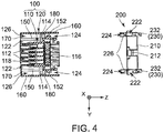
- a connector 10 according to a first embodiment of the present invention is provided with a housing 100, a lever 200 and a slider 300.
- the connector 10 further has a plurality of contacts not shown.
- the connector 10 is a connector that is mateable with and removable from a mating connector, which is not shown, along an up-down direction.
- the connector 10 is attached with a cover 400 when used.
- the up-down direction is a Z-direction. A positive Z-direction is upward while a negative Z-direction is downward.
- the housing 100 has a contact holding portion 110 and a wall portion 120 surrounding a periphery of the contact holding portion 110.
- the contact holding portion 110 has an approximately rectangular parallelepiped shape which is long in a front-rear direction orthogonal to the up-down direction.
- the front-rear direction is an X-direction.
- a positive X-direction is forward while a negative X-direction is rearward.
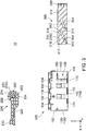
- the contact holding portion 110 is further provided with a plurality of holding holes 112. As shown in Fig.
- the holding holes 112 pierce the contact holding portion 110 and open in both of an upper surface 116 and a lower surface 118 of the contact holding portion 110.
- the holding holes 112 are used for holding the contacts not shown.
- the contacts are held in the holding holes 112 of the contact holding portion 110, respectively.
- the contacts are connected with wirings not shown, respectively. The wirings are routed upward from above the upper surface 116 of the contact holding portion 110. The contacts are visible from under the lower surface 118 of the contact holding portion 110.
- the connector 10 is a socket connector.
- the wall portion 120 has a front wall 130, a rear wall 140, a pair of inner sidewalls 150 and a pair of outer sidewalls 160.
- the wall portion 120 further has a plurality of bottom plates 170 and a plurality of connection portions 180.
- the front wall 130 covers a front surface 113 of the contact holding portion 110 and connects front ends of the inner sidewalls 150 and front ends of the outer sidewalls 160 with one another.
- the rear wall 140 covers a back surface 115 of the contact holding portion 110 and connects rear ends of the inner sidewalls 150 with each other.
- the inner sidewalls 150 cover side surfaces 114 of the contact holding portion 110 at least in part. As shown in Figs.
- each of the inner sidewalls 150 is provided with a rotational shaft 152 protruding outward in a right-left direction orthogonal to both of the front-rear direction and the up-down direction.
- the right-left direction is a Y-direction.
- the outer sidewalls 160 are located apart from and outward of the inner sidewalls 150 in the right-left direction. The outer sidewalls 160 cover not only the inner sidewalls 150 but also the side surfaces 114 of the contact holding portion 110 in part.
- the pair of the inner sidewalls 150 is connected to the contact holding portion 110 at an upper side than a middle of the contact holding portion 110 in the up-down direction.
- the front wall 130 and the rear wall 140 are connected to the contact holding portion 110.
- a receiving portion 122 is formed between the contact holding portion 110 and the surrounding walls, i.e. the front wall 130, the rear wall 140 and the pair of the inner sidewalls 150, and is positioned below connecting parts between the contact holding portion 110 and surrounding walls.
- the receiving portion 122 receives a mating housing (not shown) of the mating connector in part when the connector is mated with the mating connector.
- lever accommodation portions 124 and slider accommodation portions 126 are formed between the inner sidewalls 150 and the outer sidewalls 160.
- Each of the lever accommodation portions 124 accommodates the lever 200 in part so that the lever 200 is rotatable.
- Each of the slider accommodation portions 126 accommodates the slider 300 in part so that the slider 300 is movable in the front-rear direction.
- the lever accommodation portions 124 and the slider accommodation portions 126 communicate with each other in the up-down direction except for some parts.
- each of the bottom plates 170 connects a lower end of the inner sidewall 150 to a lower end of the outer sidewall 160 adjacent thereto.
- the bottom plates 170 function as guides when the slider 300 accommodated in the slider accommodation portions 126 in part is moved in the front-rear direction.
- each of the connection portions 180 is located on a boundary between the lever accommodation portion 124 and the slider accommodation portion 126 and connects between the inner sidewall 150 and the outer sidewall 160 which are adjacent to each other.
- the connection portions 180 function as guides together with the bottom plates 170 when the slider 300 accommodated in the slider accommodation portions 126 in part is moved in the front-rear direction.
- the front wall 130, the rear wall 140, the inner sidewalls 150, the outer sidewalls 160, the bottom plates 170 and the connection portions 180 are integrally molded using a resin (a third resin). This is for reducing the number of parts, simplifying the manufacturing process and reducing a manufacturing cost.
- the wall portion 120 may be molded integrally with at least a part of the contact holding portion 110 using a common material. As shown in Fig. 4 , the wall portion 120 is molded integrally with a part of the contact holding portion 110 using a common material in the present embodiment. It should be noted that the contact holding portion 110 consists of three parts made of three different materials, respectively. The three parts forming the contact holding portion 110 are stacked on one another in the up-down direction and integrated.
- the lever 200 has an operation portion 210 and a pair of arm portions 220.
- the operation portion 210 extends in the right-left direction.
- the arm portions 220 extend from both ends of the operation portion 210 in a direction orthogonal to the right-left direction.
- the lever 200 is partly reduced in thickness to reduce weight thereof in the present embodiment. Accordingly, the lever 200 has a lattice pattern on a surface thereof.
- each of the arm portions 220 is formed with a shaft hole 222 piercing the arm portion 220 in the right-left direction at a vicinity of an end of the arm portion 220. Furthermore, each of the arm portions 220 is formed with a guide groove 224 extending from an edge of the arm portion 220 to the shaft hole 222 in an inner surface thereof in the right-left direction.
- the guide grooves 224 extend in a direction orthogonal to the extending direction of the arm portions 220. In other words, the guide grooves 224 extend in the up-down direction when the arm portions 220 extend in the front-rear direction.
- the guide grooves 224 guide the rotational shafts 152 provided to the housing 100 to the shaft holes 222 upon attaching of the lever 200 to the housing 100.
- each of the arm portions 220 further has a pinion portion 230 having a plurality of teeth 232.
- the teeth 232 are arranged to surround partly a periphery of the shaft hole 222 when seen along the right-left direction. As mentioned later, one of the teeth 232 functions as a pressed portion 233.
- each of the arm portions 220 further has a plate-like member 234 connecting the teeth 232 of the pinion portion 230 to one another to reinforce the teeth 232.
- the plate-like member 234 is provided on one of side surfaces of the pinion portion 230.
- the plate-like members 234 are located inward of two sets of the teeth 232 in the right-left direction.
- the operation portion 210, the arm portions 220, the pinion portions 230 and the plate-like members 234 are integrally molded using a resin (a first resin). This is for reducing the number of parts, simplifying the manufacturing process and reducing a manufacturing cost.
- the first resin may be same as or different from the third resin.
- the slider 300 has a pair of side plate portions 310 and a connection plate portion 320.
- the side plate portions 310 extend in the front-rear direction.
- the connection plate portion 320 connects rear ends of the side plate portions 310 to each other.
- the slider 300 is partly reduced in thickness to reduce weight thereof in the present embodiment. Accordingly, the slider 300 has a lattice pattern on a surface thereof.
- the slider 300 is provided with two pairs of cam grooves (force transmission portions) 312 in the side plate portions 310 thereof.
- One of the pairs of the cam grooves 312 and the other pair of the cam grooves 312 are located apart from each other in the front-rear direction.
- each of the side plate portions 310 is formed with two of the cam grooves 312 which belong to different pairs and are apart from each other in the front-rear direction.
- Each of the cam grooves 312 opens downward at one end (a lower end) thereof.
- the cam groove 312 extends upward from the one end, then diagonally extends rearward and upward and further extends rearward.
- the cam groove 312 pierces the side plate portion 310 in the right-left direction except for a part (a lower end portion) of the side plate portion 310.
- the cam groove 312 may be closed at a side located outside of the slider 300 in the right-left direction.
- the cam groove 312 may be a groove having a bottom.
- each of the side plate portions 310 further has a rack portion 314 having a plurality of teeth 316 arranged along the front-rear direction.
- the side plate portion 310 further has a plate-like member 318 connecting the teeth 316 of the rack portion 314 to one another to reinforce the teeth 316.
- the plate-like members 318 are provided on outside surfaces of two sets of the teeth 316 in the right-left direction.
- the rack portion 314 is formed in a vicinity of an upper front end of the side plate portion 310.
- the side plate portions 310, the connection plate portion 320, the rack portions 314 and the plate-like members 318 are integrally molded using a resin (a second resin). This is for reducing the number of parts, simplifying the manufacturing process and reducing a manufacturing cost.
- the second resin may be same as at least one of the first resin and the third resin or may be different from both of the first resin and the third resin.
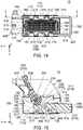
- the lever 200 is attached to the housing 100 as shown in Fig. 5 .
- the rotational shafts 152 of the housing 100 are inserted into the guide grooves 224 of the lever 200 from one end of the guide grooves 224, and the lever 200 is pressed toward the housing 100.
- the rotational shafts 152 are guided by the guide grooves 224 and inserted into the shaft holes 222.
- each of the guide grooves 224 is provided with a slope portion 226.
- the slope portion 226 is formed so that the guide groove 224 becomes shallower towards the shaft hole 222. Consequently, upon attaching the lever 200 to the housing 100, the rotational shafts 152 enlarge gradually the arm portions 220 of the lever 200 in the right-left direction and thereby deforming elastically the lever 200 and the housing 100. As a result, the rotational shafts 152 are inserted in the shaft holes 222. Once the rotational shafts 152 are inserted into the shaft holes 222, the lever 200 and the housing 100 return to original shapes. Accordingly, the rotational shafts 152 cannot come out from the shaft holes 222 easily.
- the lever 200 in a state that the lever 200 is attached to the housing 100, the lever 200 is rotatable about the rotational shafts 152 between a first position and a second position.
- the first position is a position where the arm portions 220 extends along the front-rear direction approximately and the operation portion 210 is positioned forward.
- the second position is a position where the arm portions 220 extend along the front-rear direction approximately and the operation portion 210 is positioned rearward.
- the lever 200 is positioned in the first position, the arm portion 220 is supported by the front wall 130.
- the front wall 130 of the housing 100 is formed with a stopper 132 to stop the lever 200 in the first position.
- the stopper 132 is molded integrally with at least a part of the housing 100 (the wall portion 120). This is for reducing the number of parts.
- front edges of the side plate portions 310 of the slider 300 are brought into abutment with the front wall 130.
- the lever 200 is attached to the housing 100 to be rotatable between the first position and the second position.
- the guide grooves 224 extend in the up-down direction and open upward.
- the lever 200 cannot be detached from the housing 100.
- the operation portion 210 is formed with a hook 212 to maintain the lever 200 in the second position.
- the housing 100 is formed with a stop portion 142 corresponding to the hook 212.
- the side plate portions 310 of the slider 300 are inserted into the slider accommodation portions 126 of the housing 100 in a state that the lever 200 is positioned in the first position.
- the side plate portions 310 of the slider 300 are inserted forward from behind the housing 100.
- the bottom plates 170 and the connection portions 180 serves as guides to guide the side plate portions 310.
- the tooth 316 positioned in the most forward position among the teeth 316 of each of the rack portions 314 functions as the press portion 317
- the tooth 232 nearest to the guide groove 224 among the teeth 232 of each of the pinion portions 230 functions as the pressed portion 233.
- the slider 300 has the press portions 317 while the lever 200 has the pressed portions 233 in the present embodiment.
- the slider 300 by merely inserting the slider 300 into the slider accommodation portions 126 of the housing 100 when the lever 200 is positioned in the first position, relative positions of the lever 200 and the slider 300 are defined so that the rack portions 314 and the pinion portions 230 can be appropriately engaged with each other.
- the pinion portions 230 of the lever 200 and the rack portions 314 of the slider 300 are engaged with each other and thereby forming a relation that turn of the lever 200 and front-rear direction movement of the slider 300 are exchanged with each other.
- the slider 300 is attached to the housing 100 to be movable in the front-rear direction.
- one of the teeth 316 forming the rack portion 314 is used as the press portion 317 while one of the teeth 232 forming the pinion portion 230 is used as the pressed portion 233.
- the press portion 317 may be provided separately from the teeth 316 of the rack portion 314.
- the pressed portion 233 may be provided separately from the teeth 232 of the pinion portion 230.
- the shapes of the press portion 317 and the pressed portion 233 may be freely decided.
- each of the press portion 317 and the pressed portion 233 may be rectangular in shape when seen along the light-left direction.
- an interval between the press portion 317 and the tooth 316 of the rack portion 314 adjacent to the press portion 317 may be different from an interval between the teeth 316 of the rack portion 314 adjacent to each other.
- an interval between the pressed portion 233 and the tooth 232 of the pinion portion 230 adjacent to the pressed portion 233 may be different from an interval between the teeth 232 of the pinion portion 230 adjacent to each other.
- the press portion 317 and the pressed portion 233 may be any portions provided that when the lever 200 is in the first position, moving the slider 300 forward makes the press portion 317 press the pressed portion 233 to turn the lever 200 toward the second position and to define the relative positions of the lever 200 and the slider 300.
- the press portion 317 is provided in the slider 300 to be visible when the slider 300 as a single body is seen from forward along the front-rear direction. It should be noted that the defined relative positions are necessary to allow the rack portion 314 and the pinion portion 230 to be appropriately engaged with each other.
- the lever 200 is put in the second position as shown in Figs. 9 and 11 .
- This situation can be achieved by either moving the slider 300 more forward or turning the lever 200 to the second position after the lever 200 and the slider 300 are changed into the state that they are interlocked with each other. Since the side plate portion 310 of the slider 300 is brought into abutment with the front wall 130 of the housing 100, the lever 200 is stopped in the second position. At this time, the slider 300 is positioned in a mated position.
- the cover 400 is attached to the housing 100.
- the cover 400 is attached to an upper part of the housing 100 to lead wires (not shown) forward.
- the cover 400 is attached to the housing 100 by moving the cover 400 forward from behind the housing 100.
- the cover 400 protrudes forward of the housing 100 in part in the state that the cover 400 is attached to the housing 100.
- a rotatable range of the lever 200 is limited by the cover 400 attached to the housing 100.
- the turn of the lever 200 toward the first position is limited to a position (a third position) where the arm portions 220 are brought into abutment with the regulation portions 402.
- the lever 200 in the state that the cover 400 is attached, the lever 200 is regulated so as not to be rotatable toward the first position from the third position positioned between the first position and the second position. This is because the arm portions 220 are brought into abutment with the regulation portions 402 and the lever 200 cannot be turned even if it is intended to be turned toward the first position. In this state, the lever 200 is rotatable between the third position and the second position.
- the cover 400 (or the regulation portions 402) regulates the turn of the lever 200 from the third position to the first position, and thereby the lever 200 is prevented from coming into contact with the wires connected to the connector 10.
- "the third position" represents not a specified point but a predetermined range.
- the third position includes a range from a position, where the arm portions 220 are brought into abutment with the regulation portions 402, to a position where the arm portions 220 are slightly apart from the regulation portions 402 as shown in Fig. 15 .
- “the third position” represents a rotatable range of the lever 200 that allows the cam grooves 312 of the connector 10 receive cam shafts (force receiving portion, not shown) of the mating connector.
- the regulation portions 402 are provided to be brought into abutment with the arm portions 220 of the lever 200 in the present embodiment, the regulation portions 402 may be provided to be brought into abutment with the operation portion 210.
- each of the cam grooves 312 is positioned between adjacent two of the bottom plates 170 when seen along the up-down direction.
- the cam grooves 312 can receive the cam shafts (not shown) of the mating connector.
- the connector 10 is in a mateable state (or removable state) that the connector 10 is mateable with the mating connector (not shown).
- the mating housing (not shown) of the mating connector is partly inserted into the receiving portion 122 of the connector 10 which is in the mateable state
- the cam shafts of the mating connector are inserted into the cam grooves 312. Then the cam shafts of the mating connector are brought into abutment with upper walls 342 of the cam grooves 312 and stopped in mating start positions.
- the cam shafts reach the mating start positions of the cam grooves 312.
- the mating connector is brought into the removable state (or the mateable state) that the mating connector is removable from the connector 10.
- the connector 10 can easily be removed from the mating connector.
- the present invention is not limited thereto but susceptible to various modifications and alternative forms.
- the housing 100 is provided with the rotational shafts 152 while the lever 200 is provided with the shaft holes 222 and the guide grooves 224 in the aforementioned embodiment, the housing 100 may be provided with shaft holes and guide grooves while the lever 200 may be provided with rotational shafts.
- the guide grooves also function to guide the rotational shafts to the shaft holes upon attaching the lever 200 to the housing 100.
- the guide grooves extend in the up-down direction and open upward.
- the connector 10 is provided with the cam grooves 312 while the mating connector is provided with the cam shafts (not shown).
- the connector 10 may be provided with cam shafts while the mating connector may be provided with cam grooves.
Landscapes
- Details Of Connecting Devices For Male And Female Coupling (AREA)
Applications Claiming Priority (1)
| Application Number | Priority Date | Filing Date | Title |
|---|---|---|---|
| JP2016066268A JP6647941B2 (ja) | 2016-03-29 | 2016-03-29 | コネクタ |
Publications (2)
| Publication Number | Publication Date |
|---|---|
| EP3226360A1 EP3226360A1 (en) | 2017-10-04 |
| EP3226360B1 true EP3226360B1 (en) | 2019-01-30 |
Family
ID=58094294
Family Applications (1)
| Application Number | Title | Priority Date | Filing Date |
|---|---|---|---|
| EP17156870.2A Not-in-force EP3226360B1 (en) | 2016-03-29 | 2017-02-20 | Electrical connector |
Country Status (2)
| Country | Link |
|---|---|
| EP (1) | EP3226360B1 (https=) |
| JP (1) | JP6647941B2 (https=) |
Families Citing this family (1)
| Publication number | Priority date | Publication date | Assignee | Title |
|---|---|---|---|---|
| JP7498434B2 (ja) * | 2021-05-25 | 2024-06-12 | 住友電装株式会社 | コネクタ |
Family Cites Families (9)
| Publication number | Priority date | Publication date | Assignee | Title |
|---|---|---|---|---|
| EP0655799B1 (en) * | 1993-11-26 | 1999-10-06 | Molex Incorporated | Hooded electrical connector with terminal position assurance means |
| JP3687874B2 (ja) * | 1996-10-31 | 2005-08-24 | タイコエレクトロニクスアンプ株式会社 | レバー式コネクタ |
| DE10232969B4 (de) * | 2001-07-23 | 2012-08-23 | Sumitomo Wiring Systems, Ltd. | Steckverbinder mit Verriegelungshebel |
| US6824406B1 (en) * | 2003-06-26 | 2004-11-30 | Delphi Technologies, Inc. | Electrical connector assembly |
| US7255580B2 (en) * | 2005-03-09 | 2007-08-14 | Tyco Electronics Corporation | Electrical connector and electrical connector assembly having lever assist with latch hold down mechanism |
| JP2006331991A (ja) * | 2005-05-30 | 2006-12-07 | Tyco Electronics Amp Kk | レバー式コネクタ |
| JP5370261B2 (ja) * | 2010-05-14 | 2013-12-18 | 住友電装株式会社 | コネクタ |
| JP5846105B2 (ja) * | 2012-11-13 | 2016-01-20 | 住友電装株式会社 | レバー式コネクタ |
| JP6381904B2 (ja) | 2013-12-24 | 2018-08-29 | タイコエレクトロニクスジャパン合同会社 | レバー式電気コネクタ |
-
2016
- 2016-03-29 JP JP2016066268A patent/JP6647941B2/ja not_active Expired - Fee Related
-
2017
- 2017-02-20 EP EP17156870.2A patent/EP3226360B1/en not_active Not-in-force
Non-Patent Citations (1)
| Title |
|---|
| None * |
Also Published As
| Publication number | Publication date |
|---|---|
| EP3226360A1 (en) | 2017-10-04 |
| JP6647941B2 (ja) | 2020-02-14 |
| JP2017182994A (ja) | 2017-10-05 |
Similar Documents
| Publication | Publication Date | Title |
|---|---|---|
| EP1981128B1 (en) | A lever-type connector and connector assembly | |
| US9048579B2 (en) | Lever-type connector | |
| JP5347936B2 (ja) | レバー式コネクタ | |
| EP1830436B1 (en) | A connector, connector assembly and assembling method | |
| JP5407959B2 (ja) | コネクタ | |
| EP2456020B1 (en) | Lever-type connector | |
| EP3229326B1 (en) | Connector assembly | |
| US20080200052A1 (en) | Combination of lever connector and mating connector | |
| EP3425747B1 (en) | Connector | |
| EP3232518B1 (en) | Electrical connector | |
| JP2011198515A (ja) | コネクタ | |
| US10498078B2 (en) | Lever-type connector | |
| EP2541690A1 (en) | Connector and connector assembly | |
| US9899769B2 (en) | Connector with an operating member mountable in either of two opposite orientations and locks for locking the operating member at an initial position and a connection position in either orientation | |
| EP3226360B1 (en) | Electrical connector | |
| US20170346227A1 (en) | Connector | |
| JP2012195155A (ja) | レバー治具及びコネクタ装置 | |
| JP2009037768A (ja) | 可動ガイド部材付きコネクタ | |
| CN101656364A (zh) | 电缆用连接器 | |
| US11362453B2 (en) | Connector assembly and connector | |
| CN118676682A (zh) | 配合结构 | |
| JP4442576B2 (ja) | コネクタ | |
| EP3950408B1 (en) | Charging connector | |
| JP4442575B2 (ja) | コネクタ | |
| US20210273377A1 (en) | Lever-type connector |
Legal Events
| Date | Code | Title | Description |
|---|---|---|---|
| PUAI | Public reference made under article 153(3) epc to a published international application that has entered the european phase |
Free format text: ORIGINAL CODE: 0009012 |
|
| STAA | Information on the status of an ep patent application or granted ep patent |
Free format text: STATUS: THE APPLICATION HAS BEEN PUBLISHED |
|
| AK | Designated contracting states |
Kind code of ref document: A1 Designated state(s): AL AT BE BG CH CY CZ DE DK EE ES FI FR GB GR HR HU IE IS IT LI LT LU LV MC MK MT NL NO PL PT RO RS SE SI SK SM TR |
|
| AX | Request for extension of the european patent |
Extension state: BA ME |
|
| STAA | Information on the status of an ep patent application or granted ep patent |
Free format text: STATUS: REQUEST FOR EXAMINATION WAS MADE |
|
| STAA | Information on the status of an ep patent application or granted ep patent |
Free format text: STATUS: EXAMINATION IS IN PROGRESS |
|
| 17P | Request for examination filed |
Effective date: 20180222 |
|
| RBV | Designated contracting states (corrected) |
Designated state(s): AL AT BE BG CH CY CZ DE DK EE ES FI FR GB GR HR HU IE IS IT LI LT LU LV MC MK MT NL NO PL PT RO RS SE SI SK SM TR |
|
| 17Q | First examination report despatched |
Effective date: 20180321 |
|
| GRAP | Despatch of communication of intention to grant a patent |
Free format text: ORIGINAL CODE: EPIDOSNIGR1 |
|
| STAA | Information on the status of an ep patent application or granted ep patent |
Free format text: STATUS: GRANT OF PATENT IS INTENDED |
|
| INTG | Intention to grant announced |
Effective date: 20180723 |
|
| RIN1 | Information on inventor provided before grant (corrected) |
Inventor name: KUROIWA, MASAKAZU Inventor name: OIRI, NOBUYASU Inventor name: OBATA, YUSUKE |
|
| GRAJ | Information related to disapproval of communication of intention to grant by the applicant or resumption of examination proceedings by the epo deleted |
Free format text: ORIGINAL CODE: EPIDOSDIGR1 |
|
| STAA | Information on the status of an ep patent application or granted ep patent |
Free format text: STATUS: EXAMINATION IS IN PROGRESS |
|
| GRAR | Information related to intention to grant a patent recorded |
Free format text: ORIGINAL CODE: EPIDOSNIGR71 |
|
| GRAS | Grant fee paid |
Free format text: ORIGINAL CODE: EPIDOSNIGR3 |
|
| STAA | Information on the status of an ep patent application or granted ep patent |
Free format text: STATUS: GRANT OF PATENT IS INTENDED |
|
| GRAA | (expected) grant |
Free format text: ORIGINAL CODE: 0009210 |
|
| STAA | Information on the status of an ep patent application or granted ep patent |
Free format text: STATUS: THE PATENT HAS BEEN GRANTED |
|
| INTG | Intention to grant announced |
Effective date: 20181206 |
|
| AK | Designated contracting states |
Kind code of ref document: B1 Designated state(s): AL AT BE BG CH CY CZ DE DK EE ES FI FR GB GR HR HU IE IS IT LI LT LU LV MC MK MT NL NO PL PT RO RS SE SI SK SM TR |
|
| REG | Reference to a national code |
Ref country code: GB Ref legal event code: FG4D |
|
| REG | Reference to a national code |
Ref country code: CH Ref legal event code: EP |
|
| REG | Reference to a national code |
Ref country code: AT Ref legal event code: REF Ref document number: 1094001 Country of ref document: AT Kind code of ref document: T Effective date: 20190215 |
|
| REG | Reference to a national code |
Ref country code: IE Ref legal event code: FG4D |
|
| REG | Reference to a national code |
Ref country code: DE Ref legal event code: R096 Ref document number: 602017001938 Country of ref document: DE |
|
| REG | Reference to a national code |
Ref country code: LT Ref legal event code: MG4D |
|
| REG | Reference to a national code |
Ref country code: NL Ref legal event code: MP Effective date: 20190130 |
|
| PG25 | Lapsed in a contracting state [announced via postgrant information from national office to epo] |
Ref country code: PL Free format text: LAPSE BECAUSE OF FAILURE TO SUBMIT A TRANSLATION OF THE DESCRIPTION OR TO PAY THE FEE WITHIN THE PRESCRIBED TIME-LIMIT Effective date: 20190130 Ref country code: NO Free format text: LAPSE BECAUSE OF FAILURE TO SUBMIT A TRANSLATION OF THE DESCRIPTION OR TO PAY THE FEE WITHIN THE PRESCRIBED TIME-LIMIT Effective date: 20190430 Ref country code: SE Free format text: LAPSE BECAUSE OF FAILURE TO SUBMIT A TRANSLATION OF THE DESCRIPTION OR TO PAY THE FEE WITHIN THE PRESCRIBED TIME-LIMIT Effective date: 20190130 Ref country code: FI Free format text: LAPSE BECAUSE OF FAILURE TO SUBMIT A TRANSLATION OF THE DESCRIPTION OR TO PAY THE FEE WITHIN THE PRESCRIBED TIME-LIMIT Effective date: 20190130 Ref country code: PT Free format text: LAPSE BECAUSE OF FAILURE TO SUBMIT A TRANSLATION OF THE DESCRIPTION OR TO PAY THE FEE WITHIN THE PRESCRIBED TIME-LIMIT Effective date: 20190530 Ref country code: NL Free format text: LAPSE BECAUSE OF FAILURE TO SUBMIT A TRANSLATION OF THE DESCRIPTION OR TO PAY THE FEE WITHIN THE PRESCRIBED TIME-LIMIT Effective date: 20190130 Ref country code: LT Free format text: LAPSE BECAUSE OF FAILURE TO SUBMIT A TRANSLATION OF THE DESCRIPTION OR TO PAY THE FEE WITHIN THE PRESCRIBED TIME-LIMIT Effective date: 20190130 Ref country code: ES Free format text: LAPSE BECAUSE OF FAILURE TO SUBMIT A TRANSLATION OF THE DESCRIPTION OR TO PAY THE FEE WITHIN THE PRESCRIBED TIME-LIMIT Effective date: 20190130 |
|
| REG | Reference to a national code |
Ref country code: AT Ref legal event code: MK05 Ref document number: 1094001 Country of ref document: AT Kind code of ref document: T Effective date: 20190130 |
|
| PG25 | Lapsed in a contracting state [announced via postgrant information from national office to epo] |
Ref country code: LV Free format text: LAPSE BECAUSE OF FAILURE TO SUBMIT A TRANSLATION OF THE DESCRIPTION OR TO PAY THE FEE WITHIN THE PRESCRIBED TIME-LIMIT Effective date: 20190130 Ref country code: GR Free format text: LAPSE BECAUSE OF FAILURE TO SUBMIT A TRANSLATION OF THE DESCRIPTION OR TO PAY THE FEE WITHIN THE PRESCRIBED TIME-LIMIT Effective date: 20190501 Ref country code: HR Free format text: LAPSE BECAUSE OF FAILURE TO SUBMIT A TRANSLATION OF THE DESCRIPTION OR TO PAY THE FEE WITHIN THE PRESCRIBED TIME-LIMIT Effective date: 20190130 Ref country code: IS Free format text: LAPSE BECAUSE OF FAILURE TO SUBMIT A TRANSLATION OF THE DESCRIPTION OR TO PAY THE FEE WITHIN THE PRESCRIBED TIME-LIMIT Effective date: 20190530 Ref country code: BG Free format text: LAPSE BECAUSE OF FAILURE TO SUBMIT A TRANSLATION OF THE DESCRIPTION OR TO PAY THE FEE WITHIN THE PRESCRIBED TIME-LIMIT Effective date: 20190430 Ref country code: RS Free format text: LAPSE BECAUSE OF FAILURE TO SUBMIT A TRANSLATION OF THE DESCRIPTION OR TO PAY THE FEE WITHIN THE PRESCRIBED TIME-LIMIT Effective date: 20190130 |
|
| PG25 | Lapsed in a contracting state [announced via postgrant information from national office to epo] |
Ref country code: MC Free format text: LAPSE BECAUSE OF FAILURE TO SUBMIT A TRANSLATION OF THE DESCRIPTION OR TO PAY THE FEE WITHIN THE PRESCRIBED TIME-LIMIT Effective date: 20190130 Ref country code: AL Free format text: LAPSE BECAUSE OF FAILURE TO SUBMIT A TRANSLATION OF THE DESCRIPTION OR TO PAY THE FEE WITHIN THE PRESCRIBED TIME-LIMIT Effective date: 20190130 Ref country code: DK Free format text: LAPSE BECAUSE OF FAILURE TO SUBMIT A TRANSLATION OF THE DESCRIPTION OR TO PAY THE FEE WITHIN THE PRESCRIBED TIME-LIMIT Effective date: 20190130 Ref country code: EE Free format text: LAPSE BECAUSE OF FAILURE TO SUBMIT A TRANSLATION OF THE DESCRIPTION OR TO PAY THE FEE WITHIN THE PRESCRIBED TIME-LIMIT Effective date: 20190130 Ref country code: CZ Free format text: LAPSE BECAUSE OF FAILURE TO SUBMIT A TRANSLATION OF THE DESCRIPTION OR TO PAY THE FEE WITHIN THE PRESCRIBED TIME-LIMIT Effective date: 20190130 Ref country code: IT Free format text: LAPSE BECAUSE OF FAILURE TO SUBMIT A TRANSLATION OF THE DESCRIPTION OR TO PAY THE FEE WITHIN THE PRESCRIBED TIME-LIMIT Effective date: 20190130 Ref country code: RO Free format text: LAPSE BECAUSE OF FAILURE TO SUBMIT A TRANSLATION OF THE DESCRIPTION OR TO PAY THE FEE WITHIN THE PRESCRIBED TIME-LIMIT Effective date: 20190130 Ref country code: SK Free format text: LAPSE BECAUSE OF FAILURE TO SUBMIT A TRANSLATION OF THE DESCRIPTION OR TO PAY THE FEE WITHIN THE PRESCRIBED TIME-LIMIT Effective date: 20190130 Ref country code: LU Free format text: LAPSE BECAUSE OF NON-PAYMENT OF DUE FEES Effective date: 20190220 |
|
| REG | Reference to a national code |
Ref country code: DE Ref legal event code: R097 Ref document number: 602017001938 Country of ref document: DE |
|
| REG | Reference to a national code |
Ref country code: BE Ref legal event code: MM Effective date: 20190228 |
|
| REG | Reference to a national code |
Ref country code: IE Ref legal event code: MM4A |
|
| PG25 | Lapsed in a contracting state [announced via postgrant information from national office to epo] |
Ref country code: SM Free format text: LAPSE BECAUSE OF FAILURE TO SUBMIT A TRANSLATION OF THE DESCRIPTION OR TO PAY THE FEE WITHIN THE PRESCRIBED TIME-LIMIT Effective date: 20190130 |
|
| PLBE | No opposition filed within time limit |
Free format text: ORIGINAL CODE: 0009261 |
|
| STAA | Information on the status of an ep patent application or granted ep patent |
Free format text: STATUS: NO OPPOSITION FILED WITHIN TIME LIMIT |
|
| PG25 | Lapsed in a contracting state [announced via postgrant information from national office to epo] |
Ref country code: AT Free format text: LAPSE BECAUSE OF FAILURE TO SUBMIT A TRANSLATION OF THE DESCRIPTION OR TO PAY THE FEE WITHIN THE PRESCRIBED TIME-LIMIT Effective date: 20190130 |
|
| 26N | No opposition filed |
Effective date: 20191031 |
|
| PG25 | Lapsed in a contracting state [announced via postgrant information from national office to epo] |
Ref country code: IE Free format text: LAPSE BECAUSE OF NON-PAYMENT OF DUE FEES Effective date: 20190220 |
|
| PG25 | Lapsed in a contracting state [announced via postgrant information from national office to epo] |
Ref country code: BE Free format text: LAPSE BECAUSE OF NON-PAYMENT OF DUE FEES Effective date: 20190228 Ref country code: SI Free format text: LAPSE BECAUSE OF FAILURE TO SUBMIT A TRANSLATION OF THE DESCRIPTION OR TO PAY THE FEE WITHIN THE PRESCRIBED TIME-LIMIT Effective date: 20190130 |
|
| PG25 | Lapsed in a contracting state [announced via postgrant information from national office to epo] |
Ref country code: TR Free format text: LAPSE BECAUSE OF FAILURE TO SUBMIT A TRANSLATION OF THE DESCRIPTION OR TO PAY THE FEE WITHIN THE PRESCRIBED TIME-LIMIT Effective date: 20190130 |
|
| PG25 | Lapsed in a contracting state [announced via postgrant information from national office to epo] |
Ref country code: MT Free format text: LAPSE BECAUSE OF NON-PAYMENT OF DUE FEES Effective date: 20190220 |
|
| REG | Reference to a national code |
Ref country code: CH Ref legal event code: PL |
|
| PG25 | Lapsed in a contracting state [announced via postgrant information from national office to epo] |
Ref country code: LI Free format text: LAPSE BECAUSE OF NON-PAYMENT OF DUE FEES Effective date: 20200229 Ref country code: CH Free format text: LAPSE BECAUSE OF NON-PAYMENT OF DUE FEES Effective date: 20200229 |
|
| PG25 | Lapsed in a contracting state [announced via postgrant information from national office to epo] |
Ref country code: CY Free format text: LAPSE BECAUSE OF FAILURE TO SUBMIT A TRANSLATION OF THE DESCRIPTION OR TO PAY THE FEE WITHIN THE PRESCRIBED TIME-LIMIT Effective date: 20190130 |
|
| PG25 | Lapsed in a contracting state [announced via postgrant information from national office to epo] |
Ref country code: HU Free format text: LAPSE BECAUSE OF FAILURE TO SUBMIT A TRANSLATION OF THE DESCRIPTION OR TO PAY THE FEE WITHIN THE PRESCRIBED TIME-LIMIT; INVALID AB INITIO Effective date: 20170220 |
|
| GBPC | Gb: european patent ceased through non-payment of renewal fee |
Effective date: 20210220 |
|
| PG25 | Lapsed in a contracting state [announced via postgrant information from national office to epo] |
Ref country code: GB Free format text: LAPSE BECAUSE OF NON-PAYMENT OF DUE FEES Effective date: 20210220 |
|
| PG25 | Lapsed in a contracting state [announced via postgrant information from national office to epo] |
Ref country code: MK Free format text: LAPSE BECAUSE OF FAILURE TO SUBMIT A TRANSLATION OF THE DESCRIPTION OR TO PAY THE FEE WITHIN THE PRESCRIBED TIME-LIMIT Effective date: 20190130 |
|
| PGFP | Annual fee paid to national office [announced via postgrant information from national office to epo] |
Ref country code: FR Payment date: 20230110 Year of fee payment: 7 |
|
| PGFP | Annual fee paid to national office [announced via postgrant information from national office to epo] |
Ref country code: DE Payment date: 20221229 Year of fee payment: 7 |
|
| REG | Reference to a national code |
Ref country code: DE Ref legal event code: R119 Ref document number: 602017001938 Country of ref document: DE |
|
| PG25 | Lapsed in a contracting state [announced via postgrant information from national office to epo] |
Ref country code: DE Free format text: LAPSE BECAUSE OF NON-PAYMENT OF DUE FEES Effective date: 20240903 |
|
| PG25 | Lapsed in a contracting state [announced via postgrant information from national office to epo] |
Ref country code: FR Free format text: LAPSE BECAUSE OF NON-PAYMENT OF DUE FEES Effective date: 20240229 |
|
| PG25 | Lapsed in a contracting state [announced via postgrant information from national office to epo] |
Ref country code: FR Free format text: LAPSE BECAUSE OF NON-PAYMENT OF DUE FEES Effective date: 20240229 Ref country code: DE Free format text: LAPSE BECAUSE OF NON-PAYMENT OF DUE FEES Effective date: 20240903 |