EP3223585B2 - Kochfeldvorrichtung - Google Patents
Kochfeldvorrichtung Download PDFInfo
- Publication number
- EP3223585B2 EP3223585B2 EP17157771.1A EP17157771A EP3223585B2 EP 3223585 B2 EP3223585 B2 EP 3223585B2 EP 17157771 A EP17157771 A EP 17157771A EP 3223585 B2 EP3223585 B2 EP 3223585B2
- Authority
- EP
- European Patent Office
- Prior art keywords
- unit
- housing unit
- housing
- assembled state
- hob
- Prior art date
- Legal status (The legal status is an assumption and is not a legal conclusion. Google has not performed a legal analysis and makes no representation as to the accuracy of the status listed.)
- Active
Links
Images


Classifications
-
- F—MECHANICAL ENGINEERING; LIGHTING; HEATING; WEAPONS; BLASTING
- F24—HEATING; RANGES; VENTILATING
- F24C—DOMESTIC STOVES OR RANGES ; DETAILS OF DOMESTIC STOVES OR RANGES, OF GENERAL APPLICATION
- F24C15/00—Details
- F24C15/20—Removing cooking fumes
- F24C15/2042—Devices for removing cooking fumes structurally associated with a cooking range e.g. downdraft
-
- F—MECHANICAL ENGINEERING; LIGHTING; HEATING; WEAPONS; BLASTING
- F24—HEATING; RANGES; VENTILATING
- F24C—DOMESTIC STOVES OR RANGES ; DETAILS OF DOMESTIC STOVES OR RANGES, OF GENERAL APPLICATION
- F24C15/00—Details
- F24C15/10—Tops, e.g. hot plates; Rings
- F24C15/102—Tops, e.g. hot plates; Rings electrically heated
-
- H—ELECTRICITY
- H05—ELECTRIC TECHNIQUES NOT OTHERWISE PROVIDED FOR
- H05B—ELECTRIC HEATING; ELECTRIC LIGHT SOURCES NOT OTHERWISE PROVIDED FOR; CIRCUIT ARRANGEMENTS FOR ELECTRIC LIGHT SOURCES, IN GENERAL
- H05B6/00—Heating by electric, magnetic or electromagnetic fields
- H05B6/02—Induction heating
- H05B6/10—Induction heating apparatus, other than furnaces, for specific applications
- H05B6/12—Cooking devices
- H05B6/1209—Cooking devices induction cooking plates or the like and devices to be used in combination with them
Definitions
- the invention relates to a hob device according to the preamble of patent claim 1.
- a hotplate which contains a hob device as a subassembly.
- a hob device is already known which has a housing unit and a web-like reinforcement unit.
- the reinforcement unit is fastened to a base of the housing unit in an assembled state and is intended to reinforce the housing unit.
- the object of the invention is in particular to provide a generic device with improved properties with regard to high stability. The object is achieved according to the invention by the features of patent claim 1, while advantageous embodiments and further developments of the invention can be taken from the subclaims.
- the invention is based on a hob device, in particular an induction hob device, with a housing unit and with at least one web-like reinforcement unit, which is provided for reinforcing the housing unit and is permanently attached to the housing unit without tools, at least in an assembled state.
- the reinforcement unit has at least one fastening element which, in the assembled state, is provided for fastening at least to one side wall of the housing unit, wherein the reinforcement unit has at least one further fastening element which, in the assembled state, is provided for fastening at least to another side wall of the housing unit.
- a "cooktop device” is to be understood in particular as at least one part, in particular a subassembly, of a cooktop, in particular an induction cooktop, wherein in particular accessory units for the cooktop can also be included.
- the cooktop device can also comprise the entire cooktop, in particular the entire induction cooktop.
- a "housing unit” is to be understood in particular as a unit which, in the assembled state, is provided to at least partially delimit and/or define at least one receiving space, in particular designed as a cavity, for receiving and/or storing at least one component.
- the component could, for example, be at least one heating unit and/or a control unit and/or a supply unit and/or a user interface.
- the housing unit and a hob plate, in particular together at least essentially delimit the receiving space.
- the receiving space is in particular designed as a hollow space.
- the housing unit in particular absorbs a weight force of components at least to a large extent and/or transfers the weight force to at least one further unit, such as the hob plate.
- the hob device in particular has the hob plate.
- the housing unit is advantageously designed as an outer housing unit and in particular together with the hob plate defines an outer hob housing at least essentially.
- a "web-like" reinforcement unit is to be understood in particular as a unit which has a longitudinal extension which is at least 4 times, in particular at least 5 times, advantageously at least 7 times, particularly advantageously at least 10 times and preferably at least 20 times as large as a smallest transverse extension of the reinforcement unit and in particular additionally as a second smallest transverse extension of the reinforcement unit.
- the web-like reinforcement unit has at least one transverse extension when viewed from a projection in a plane which is aligned in particular parallel to a main extension plane of the housing unit, which is a maximum of 25%, in particular a maximum of 20%, advantageously a maximum of 15%, particularly advantageously a maximum of 10% and preferably a maximum of 5% of a longitudinal extension of the reinforcement unit.
- a "longitudinal extension" of an object is to be understood in particular as an extension of the object in a longitudinal extension direction of the object.
- a “longitudinal extension direction” of an object is to be understood in particular as a direction which is aligned parallel to a longest side of a smallest imaginary geometric cuboid which just completely encloses the object.
- extension of an object is to be understood in particular as a maximum distance between two points of a vertical projection of the object onto a plane.
- the smallest transverse extension of the reinforcement unit and the second smallest transverse extension of the reinforcement unit are in particular aligned perpendicular to the longitudinal extension of the reinforcement unit.
- the smallest transverse extension of the reinforcement unit and the second smallest transverse extension of the reinforcement unit are aligned perpendicular to one another.
- a "main extension plane" of an object is to be understood in particular as a plane which is parallel to a largest side surface of a smallest imaginary geometric cuboid which just completely encloses the object and in particular runs through the center of the cuboid.
- the reinforcement unit is in particular designed differently from the housing unit and in particular can be moved relative to the housing unit in at least one disassembled state.
- the reinforcement unit is intended to divide the receiving space at least partially delimited by the housing unit into at least two subspaces which are arranged next to one another in particular in a horizontal direction.
- the horizontal direction is in particular aligned parallel to a main extension plane of the housing unit and/or perpendicular to a direction of gravity.
- the reinforcement unit is preferably provided to at least substantially prevent deformation of the housing unit when an external force acts on the housing unit.
- the external force could in particular have a value of at least 50 N, in particular of at least 75 N, advantageously of at least 100 N, particularly advantageously of at least 125 N, preferably of at least 150 N and particularly preferably of at least 175 N.
- the external force could be caused and/or induced by a trigger unit.
- the reinforcement unit is attached to the housing unit by means of a connection that can only be released using a tool.
- a "fastening element” is to be understood as an element that is provided to fasten the reinforcement unit at least to the side wall of the housing unit by means of a connection that can only be released using a tool.
- the fastening of the reinforcement unit to the side wall of the housing unit by the fastening element differs from a connection that can be released without tools.
- the fastening element is in particular intended to fasten the reinforcement unit in the assembled state to the side wall of the housing unit by means of a force-fitting and/or by means of a form-fitting and/or by means of a material-fitting connection.
- a "side wall" of the housing unit is to be understood in particular as a unit which is intended to at least substantially delimit the housing unit in the assembled state at least in a horizontal direction aligned parallel to the main extension plane of the housing unit and/or which is intended to form a main delimitation of the housing unit in the horizontal direction in the assembled state.
- the side wall could be intended to delimit the housing unit in addition to a delimitation in the horizontal direction at least partially in a vertical direction aligned at least substantially perpendicular to the main extension plane of the housing unit.
- the side wall of the housing unit is in particular a lateral delimitation of the housing unit and in particular has a main extension plane which is at least substantially perpendicular to a main extension plane of the housing unit.
- a normal vector to the main extension plane of the side wall is aligned in an installed position in particular at least substantially perpendicular to a direction of gravity.
- the vertical direction is aligned in particular perpendicular to the main extension plane of the housing unit and/or parallel to a direction of gravity.
- Provided is to be understood in particular as specially designed and/or equipped.
- the fact that an object is provided for a specific function is to be understood in particular as meaning that the object fulfills and/or carries out this specific function in at least one application and/or operating state.
- the housing unit can retain its original shape in the event of heavy loads acting on the housing unit.
- the reinforcement unit attached at least to the side wall can in particular divide the longitudinal extent of the housing unit into smaller sub-areas. This can in particular prevent deformation of the housing unit, which in particular can prevent interactions with adjacent kitchen components, which could be caused by deformation of the housing unit, for example.
- a correct positioning of components of the hob device, such as at least one heating unit and/or a user interface, in particular relative to the hob plate can be ensured and their correct function can be guaranteed.
- the fastening element could be fastened to the side wall of the housing unit in the assembled state by means of a screw connection.
- the fastening element is fastened to the side wall of the housing unit in the assembled state by means of a connection other than a material connection.
- the fastening element is fastened to the side wall of the housing unit in the assembled state by means of at least one rivet connection. This makes it possible to achieve a particularly stable design.
- the reinforcement unit has at least one further fastening element which, in the assembled state, is provided for fastening at least to a further side wall of the housing unit.
- the further fastening element could be provided for fastening to a further side wall adjacent to the side wall, which could in particular be aligned at least substantially perpendicular to the side wall.
- the further fastening element could in particular form an at least substantially triangular shape together with the side wall and with the further side wall when viewed in a projection in a plane which is aligned in particular parallel to a main extension plane of the housing unit.
- the reinforcement unit has at least one further fastening element which, in the assembled state, is provided for fastening at least to a further side wall of the housing unit opposite the side wall.
- the further fastening element could be fastened to the further side wall of the housing unit by means of a screw connection in the assembled state.
- the further fastening element is fastened to the further side wall of the housing unit in the assembled state by means of a connection other than a material connection.
- the further fastening element is fastened in the assembled state to the further side wall of the housing unit by means of at least one rivet connection.
- a longitudinal extension direction of the reinforcement unit is in particular aligned at least substantially perpendicular to a main extension plane of the side wall and/or, in particular and, to a main extension plane of the further side wall.
- the reinforcement unit forms at least one reinforcement strut, which is provided for reinforcing the housing unit.
- the housing unit can in particular be divided into several subsections and thus in particular optimally stabilized.
- the reinforcement unit has at least one support element which, in the assembled state, is provided for fastening at least to a base of the housing unit.
- the support element could be fastened to the base of the housing unit in the assembled state by means of a screw connection.
- the support element is fastened to the base of the housing unit in the assembled state by means of a connection other than a material connection.
- the support element is fastened to the base of the housing unit in the assembled state by means of at least one rivet connection.
- the support element has in particular a main extension plane which is aligned in particular at least substantially perpendicular to a longitudinal extension direction of the reinforcement unit and/or at least substantially parallel to a main extension plane of the housing unit.
- a “base” of the housing unit is to be understood in particular as a unit which is provided to at least substantially delimit the housing unit in the assembled state at least in the vertical direction and/or to form a main delimitation of the housing unit in the vertical direction in the assembled state.
- the base in an installed position, the base forms a wall facing a substrate and/or a wall of the housing unit that delimits the housing unit, in particular the receiving space delimited by the housing unit.
- the base is in particular intended for setting up at least one component.
- the base in particular has a main extension plane, which is in particular aligned at least substantially parallel to a main extension plane of the hob plate and/or at least substantially parallel to a main extension plane of the housing unit. This makes it possible in particular to reinforce the housing unit in a plane that is aligned at least substantially perpendicular to the side wall.
- the reinforcement unit has at least one support element which is intended to provide at least one support surface for at least one room divider element in the assembled state.
- the hob device has the room divider element.
- a "room divider element" is to be understood in particular as an element which is intended to divide at least one room, in particular at least the receiving room, into at least two sub-rooms in the assembled state.
- the room divider element is designed as a plate.
- the room divider element is preferably arranged between at least one heating unit and at least one electronic unit, such as a control unit and/or a supply unit and/or hob electronics.
- the room divider element is advantageously intended to divide the room, in particular the receiving room, into large areas.
- the room divider element has in particular a surface area of at least 0.1 m 2 , in particular of at least 0.2 m 2 , advantageously of at least 0.3 m 2 , particularly advantageously of at least 0.35 m 2 and preferably of at least 0.4 m 2 .
- the room divider element has a longitudinal extent of at least 30 cm, in particular of at least 40 cm, advantageously of at least 50 cm, particularly advantageously of at least 60 cm and preferably of at least 80 cm.
- the room divider element has in particular a transverse extent of at least 30 cm, in particular of at least 40 cm, advantageously of at least 50 cm, particularly advantageously of at least 55 cm and preferably of at least 60 cm.
- the room divider element is in particular designed as a shielding element which is in particular intended to shield at least one electronic unit, such as a control unit, from electromagnetic radiation caused by at least one heating unit, in particular thermal radiation and/or magnetic fields and/or electrical fields.
- the room divider element consists at least to a large extent of a non-magnetic and electrically conductive material, in particular of metal and advantageously of aluminum. "At least to a large extent” is to be understood in particular as a proportion of at least 70%, in particular of at least 80%, advantageously of at least 90% and preferably of at least 95%. This means that additional components for supporting the room divider element can be dispensed with and/or a cost-effective design can be achieved.
- a complete stabilization of the housing unit can be achieved.
- a position of at least one heating unit arranged above the room divider element can be stabilized and/or the heating unit can be held in a designated position, which in particular can ensure optimal heating of cooking utensils placed thereon.
- the reinforcement unit has at least one position securing element which is provided to secure a position of an inner housing unit relative to the housing unit in the assembled state.
- the position securing element is in particular provided to prevent movement of the inner housing unit relative to the housing unit at least in the vertical direction in the assembled state. to avoid.
- the reinforcement unit is provided to clamp at least part of the inner housing unit between the position securing element and the housing unit in the assembled state.
- the hob device has the inner housing unit.
- An "inner housing unit" is to be understood in particular as a unit which in the assembled state is at least largely hidden from an operator and/or inaccessible and which is provided in particular to supplement and/or support the housing unit.
- the inner housing unit could, for example, be provided to at least substantially electrically insulate electrical and/or electronic hob components from the housing unit, which could in particular be designed to be electrically conductive, wherein the inner housing unit could in particular be made of at least one electrically insulating material.
- the inner housing unit In the assembled state, the inner housing unit is in particular at least largely surrounded by the housing unit. This can in particular prevent movement of the inner housing unit relative to the housing unit, in particular when transporting the hob device.
- the reinforcement unit can take on several functions simultaneously, which in particular means that additional components and/or measures for securing a position of the inner housing unit can be dispensed with.
- the reinforcement unit is formed in one piece.
- the reinforcement unit has at least one metallic material and is advantageously formed at least to a large extent from at least one metallic material.
- the metallic material could be, for example, a sheet metal, in particular a stamped and bent sheet metal, and/or a steel, in particular a galvanized steel.
- the term "in one piece" is to be understood in particular as at least materially connected, for example by a welding process, an adhesive process, an injection molding process and/or another process that appears to be useful to a person skilled in the art, and/or advantageously formed in one piece, for example by production from a cast and/or by production using a single or multi-component injection molding process and advantageously from a single blank. This makes it possible to achieve a high level of stability in particular.
- the reinforcement unit in the assembled state is arranged in particular in a close area and advantageously in an edge area of a housing recess of the housing unit and is provided for reinforcing the housing unit in an area of a housing recess of the housing unit.
- the housing recess is arranged in an area around a center point and/or center of gravity of the base of the housing unit.
- a geometric center of gravity of the housing recess and a center of gravity of the base of the housing unit are in particular at least substantially identical.
- the area of the housing recess in particular comprises the housing recess and a close area of the housing recess.
- the area of the housing recess is in particular delimited by an imaginary line which has a distance of a maximum of 85%, in particular a maximum of 80%, advantageously a maximum of 75%, particularly advantageously a maximum of 70% and preferably a maximum of 60% of a longitudinal extension and/or a transverse extension of the housing recess from a geometric center of gravity of the housing recess.
- the reinforcement unit could, for example, at least partially bridge the housing recess. Alternatively or additionally, the reinforcement unit could be arranged at least partially in an edge region of the housing recess.
- the reinforcement unit has a distance of a maximum of 50 mm, in particular a maximum of 30 mm, advantageously a maximum of 20 mm, particularly advantageously a maximum of 10 mm and preferably a maximum of 5 mm from a lateral edge delimiting the housing recess.
- a "housing recess" of the housing unit is to be understood in particular as a hole and/or an opening in the housing unit, in particular at least in the bottom of the housing unit.
- at least one wall of the housing unit delimits the housing recess from at least two, in particular from at least three and advantageously from at least four sides.
- At least one wall of the housing unit delimits the housing recess with respect to a geometric center of gravity of the housing recess by an angular range of at least 180°, in particular of at least 270°, advantageously of at least 300° and preferably of at least 330°.
- the wall of the housing unit delimiting the housing recess is in particular formed at least to a large extent by the bottom of the housing unit.
- the housing recess has in particular a longitudinal extension of at least 50 mm, in particular of at least 100 mm, advantageously of at least 150 mm, particularly advantageously of at least 200 mm, preferably of at least 250 mm and particularly preferably of at least 300 mm.
- the housing recess has in particular a transverse extension of at least 100 mm, in particular of at least 150 mm, advantageously of at least 200 mm, particularly advantageously of at least 250 mm, preferably of at least 300 mm and particularly preferably of at least 450 mm.
- the hob plate has at least one plate recess, which is arranged and/or designed in particular to correspond to the housing recess.
- the housing unit in particular a geometric center of gravity of the housing recess, is in an installation position arranged below the plate recess, in particular below a geometric center of gravity of the plate recess. This allows unstable partial areas of the housing unit and/or weak points of the housing unit to be specifically reinforced by means of the reinforcement unit.
- the hob device has an extractor unit which, in an installed position and in particular in the assembled state, is arranged, in particular fastened, below the housing unit, in particular below the housing recess of the housing unit.
- the extractor unit In the assembled state, the extractor unit is fastened in particular to the bottom of the housing unit.
- the extractor unit is arranged centrally below the housing unit.
- the extractor unit When viewed from a projection in a plane which is aligned in particular parallel to a main extension plane of the housing unit, the extractor unit is arranged in particular in a center and/or center of gravity of the housing unit, wherein the housing unit in particular surrounds the extractor unit.
- An "extractor unit” is to be understood in particular as a unit which is intended to extract and/or filter vapors arising in at least one operating state from at least one cooking area, and which is in particular intended to at least transport these vapors away from the cooking area.
- the extractor unit has in particular at least one grease filter, which is intended to at least substantially absorb fat particles dissolved in the vapors generated in at least one operating state and/or to at least substantially remove them from the vapors.
- the extractor unit has at least one ventilation element, which is intended to provide at least one suction flow for vapors generated in the operating state in at least one operating state and in particular to at least transport the vapors extracted in particular by means of the suction flow away from the cooking area.
- the extractor unit could be intended to remove the vapors generated in the operating state from the cooking area and also from a cooking chamber and, for example, to feed them to at least one exhaust air line.
- the extractor unit could in particular be intended to transport the vapors generated in the operating state from the cooking area to at least one further part of the cooking chamber.
- a "cooking area” is to be understood in particular as a sub-area of a cooking space in which a cooking process takes place in the operating state and in which, in particular, vapors generated during the cooking process escape from a heated cooking vessel and which advantageously extends in an installed position at least to a large extent above the hob plate on which the heated cooking vessel is in particular placed.
- a "cooking area” is to be understood in particular as a space in which a hob comprising the hob device is set up and/or arranged.
- the extractor unit In an installed position, the extractor unit is in particular at a smaller distance from a base than the housing unit, in particular than the base of the housing unit.
- the housing unit In the assembled state, the housing unit is at least largely arranged in particular between the extractor unit and the hob plate, which is in particular intended for setting up cooking vessels and/or is arranged facing an operator. This means that an extractor hood arranged above a hob plate can be dispensed with and/or a space-saving design can be achieved.
- the reinforcement unit allows the extraction unit to be arranged in particular below the housing unit and at the same time a high stability of the housing unit can be achieved.
- the housing recess is designed as an air supply opening for the extraction unit.
- the extraction unit is in particular intended to suck in and/or discharge vapors and/or air through the housing recess and in particular additionally through the plate recess in at least one operating state. This makes it possible in particular to achieve a compact design.
- a particularly high level of stability can be achieved by a hob, in particular by an induction hob, with at least one hob device according to the invention, in particular with at least one induction hob device according to the invention.
- the stability can be further increased by a method for assembling at least one hob device according to the invention, in particular an induction hob device according to the invention, with a housing unit and with at least one web-like reinforcement unit, which is provided for reinforcing the housing unit and is fastened in at least one assembled state, in particular without tools, in a non-detachable manner to at least one side wall of the housing unit.
- a method for assembling at least one hob device according to the invention in particular an induction hob device according to the invention, with a housing unit and with at least one web-like reinforcement unit, which is provided for reinforcing the housing unit and is fastened in at least one assembled state, in particular without tools, in a non-detachable manner to at least one side wall of the housing unit.
- the hob device should not be limited to the application and embodiment described above.
- the hob device can have a number of individual elements, components and units that differs from the number stated herein in order to fulfill a function described herein.
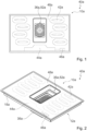
- Fig. 1 shows a hob 40a, which is designed as an induction hob, with a hob device 10a, which is designed as an induction hob device.
- the hob device 10a has a hob plate 48a. In an assembled state, the hob plate 48a forms part of a hob outer housing.
- the hob plate 48a is intended for placing cooking utensils (not shown).
- the hob device 10a has a plurality of heating units 42a.
- the heating units 42a are designed as induction heating units.
- the heating units 42a are arranged in the form of a matrix.
- the heating units could in particular be part of a classic hob, in which there could be fixed heating zones defined in particular by a position of the heating units, which could in particular be marked on the hob plate.
- the cooking surface device 10a has eight heating units 42a.
- Four of the heating units 42a define a variable cooking surface area.
- the heating units 42a defining a variable cooking surface area are arranged in a single row.
- the heating units 42a are intended to heat cooking utensils placed on the cooking surface plate 48a above the heating units 42a.
- the hob device 10a has a user interface 44a for inputting and/or selecting operating parameters, for example a heating power and/or a heating power density and/or a heating zone.
- the user interface 44a is provided for outputting a value of an operating parameter to an operator.
- the hob device 10a has a control unit 46a.
- the control unit 46 is designed to carry out actions and/or change settings depending on operating parameters entered via the user interface 44a. In an operating state, the control unit 46a regulates a power supply to the heating units 42a.
- the hob device 10a has a housing unit 12a (cf. Fig. 2 to 4 , 6 and 7 ). In an installation position, the housing unit 12a is arranged below the hob plate 48a. In the assembled state, the housing unit 12a is fastened to the hob plate 48a. In the assembled state, the housing unit 12a partially defines a receiving space 50a (cf. Fig. 4 , 6 and 7 ).
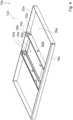
- the hob device 10a has two web-like reinforcement units 14a (cf. Fig. 4 to 7 ).
- the reinforcement units 14a are arranged parallel to one another in the assembled state.
- a first of the reinforcement units 14a has a longitudinal extension direction which is aligned parallel to a longitudinal extension direction of a second of the reinforcement units 14a.
- the housing unit 12a has a housing recess 36 (cf. Fig. 1, 2 and 4 ).
- the hob plate 48a has a plate recess 52a (cf. Fig. 1 and 2 ). In the installed position, the housing recess 36 is arranged substantially below the plate recess 52a.
- the housing recess 36a and the plate recess 52a are arranged corresponding to one another.
- the reinforcement units 14a are arranged on both sides of the housing recess 36a of the housing unit 12a. Only one of the reinforcement units 14a is described below.
- the reinforcement unit 14a which is provided for reinforcing the housing unit 12a, is fastened to the housing unit 12a (cf. Fig. 4 , 6 and 7 ).
- the reinforcement unit 14a is attached to the housing unit 12a at several locations.
- the reinforcement unit 14a has a fastening element 16a (cf. Fig. 5 ).
- the fastening element 16a has a main extension plane which is aligned substantially perpendicular to a longitudinal extension direction of the reinforcement unit 14a.
- the fastening element 16a is provided for fastening to a side wall 18a of the housing unit 12a.
- the fastening element 16a in the assembled state is fastened to the side wall 18a of the housing unit 12a by means of a rivet connection.
- the reinforcement unit 14a has a further fastening element 20a (cf. Fig. 4 to 7 ).
- the further fastening element 20a has a main extension plane which is aligned substantially perpendicular to a longitudinal extension direction of the reinforcement unit 14a. In the assembled state, the further fastening element 20a is provided for fastening to a further side wall 22a of the housing unit 12a.
- the further side wall 22a and the side wall 20a are opposite walls of the housing unit 12a.
- the reinforcement unit 14a connects the further side wall 22a and the side wall 20a to one another.
- the reinforcement unit 14a divides the receiving space 50a into subspaces.
- the further fastening element 20a is fastened in the assembled state to the further side wall 22a of the housing unit 12a by means of a rivet connection.
- the reinforcement unit 14a has two support elements 24a (cf. Fig. 4 to 7 ). Only one of the support elements 24a is described below.
- the support element 24a In the assembled state, the support element 24a is provided for supporting the reinforcement unit 14a on a base 26a of the housing unit 12a. In the assembled state, the support element 24a is provided for fastening to the base 26a of the housing unit 12a.
- the support element 24a has a main extension plane which, in the assembled state, is aligned substantially parallel to a main extension plane of the housing unit 12a.
- the reinforcement unit 14a has two support elements 28a (cf. Fig. 4 to 6 ). Only one of the support elements 28a is described below. In the assembled state, the support element 28a provides a support surface for a room divider element 30a.
- the hob device 10a has the room divider element 30a (cf. Fig. 6 ).
- the room divider element 30a In the assembled state, the room divider element 30a is arranged on a side of the reinforcement unit 14a opposite the base 26a of the housing unit 12a.
- the room divider element 30a In the assembled state, the room divider element 30a is arranged between the hob plate 48a and the housing unit 12a.
- the room divider element 30a has a main extension plane which, in the assembled state, is aligned substantially parallel to the main extension plane of the housing unit 12a.
- the support element 28a In the assembled state, the support element 28a is intended for attachment to the room divider element 30a.
- the support element 28a has a main extension plane which, in the assembled state, is aligned substantially parallel to the main extension plane of the housing unit 12a.
- the hob device 10a has two inner housing units 34a (cf. Fig. 7 ). Only one of the inner housing units 34a is shown. Only one of the inner housing units 34a is described below.
- the inner housing unit 34a In the installation position and in the assembled state, the inner housing unit 34a is arranged above the base 26a of the housing unit 12a. In the installation position and in the assembled state, the inner housing unit 34a is placed on the base 26a of the housing unit 12a.
- the reinforcement unit 14a has three position securing elements 32a (cf. Fig. 4 to 6 ). Only one of the position securing elements 32a is described below. In the assembled state, the position securing element 32a secures a position of the inner housing unit 34a relative to the housing unit 12a.
- the position securing element 32a presses a portion of the inner housing unit 34a onto the base 26a of the housing unit 12a. In the assembled state, the position securing element 32a clamps the portion of the inner housing unit 34a between the position securing element 32a and the base 26a of the housing unit 12a (cf. Fig. 7 ).
- the position securing element 32a is designed as a feature of the reinforcement unit 14a.
- the position securing element 32a is designed as a punched portion of the reinforcement unit 14a.
- the reinforcement unit 14a is designed in one piece.
- the reinforcement unit 14a is provided for reinforcing the housing unit 12a in a region of the housing recess 36a of the housing unit 12a. In the assembled state, the reinforcement unit 14a borders on the housing recess 36a of the housing unit 12a.
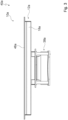
- the hob device 10a has an extractor unit 38a (cf. Fig. 2 and 3 ).
- the trigger unit 38a In the assembled state, the trigger unit 38a is fastened to the housing unit 12a. In the installed position, the trigger unit 38a is arranged below the housing unit 12a. In the installed position, the trigger unit 38a is arranged below the housing recess 36a.
- the housing recess 36a is designed as an air supply opening for the extractor unit 38a.
- the plate recess 52a is designed as an air supply opening for the extractor unit 38a.
- the extractor unit 38a sucks vapors from a cooking area through the plate recess 52a and through the housing recess 36a, which is located above the hob plate in particular in the installation position. 48a is located.
- the reinforcement unit 14a is attached to the side wall 18a of the housing unit 12a.
- the reinforcement unit 14a is attached to the further side wall 22a of the housing unit 12a.
- the reinforcement unit 14a is attached to the base 26a of the housing unit 12a.
- the room divider element 30a is placed on the support surface provided by the reinforcement unit 14a, in particular by the support element 28a of the reinforcement unit 14a, and attached to the reinforcement unit 14a.
- the housing unit 12a is attached to the hob plate 48a.
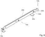
- FIG. 8 A further embodiment of the invention is shown.
- the following descriptions are essentially limited to the differences between the embodiments, whereby with regard to the same components, features and functions, reference is made to the description of the embodiment of the Fig. 1 to 7
- the letter a in the reference numerals of the embodiment in the Fig. 1 to 7 by the letter b in the reference numerals of the embodiment of the Fig. 8 With regard to identically designated components, in particular with regard to components with the same reference numerals, reference can also be made to the drawings and/or the description of the embodiment of the Fig. 1 to 7 be referred to.
- Fig. 8 shows a reinforcement unit 14b of an alternative hob device 10b.
- the reinforcement unit 14b has a single support element 28b.
- the support element 28b provides a support surface for a room divider element 30b.
- the support element 28b extends over a significant portion of a longitudinal extension of the reinforcement unit 14b.
Landscapes
- Engineering & Computer Science (AREA)
- Chemical & Material Sciences (AREA)
- Combustion & Propulsion (AREA)
- Mechanical Engineering (AREA)
- General Engineering & Computer Science (AREA)
- Physics & Mathematics (AREA)
- Electromagnetism (AREA)
- Baking, Grill, Roasting (AREA)
Description
- Die Erfindung betrifft eine Kochfeldvorrichtung nach dem Oberbegriff des Patentanspruchs 1.
- Aus dem Dokument
DE 202009000990U U1 - Die Erfindung geht aus von einer Kochfeldvorrichtung, insbesondere von einer Induktionskochfeldvorrichtung, mit einer Gehäuseeinheit und mit zumindest einer stegartigen Verstärkungseinheit, welche zu einer Verstärkung der Gehäuseeinheit vorgesehen ist und wenigstens in einem montierten Zustand an der Gehäuseeinheit werkzeuglos unlösbar befestigt ist.
- Es ist vorgesehen, dass die Verstärkungseinheit zumindest ein Befestigungselement aufweist, das in dem montierten Zustand zu einer Befestigung zumindest an einer Seitenwand der Gehäuseeinheit vorgesehen ist, wobei die Verstärkungseinheit zumindest ein weiteres Befestigungseiement aufweist, das in dem montierten Zustand zu einer Befestigung zumindest an einer weiteren Seitenwand der Gehäuseeinheit vorgesehen ist. Unter einer "Kochfeldvorrichtung" soll insbesondere zumindest ein Teil, insbesondere eine Unterbaugruppe, eines Kochfelds, insbesondere eines Induktionskochfelds, verstanden werden, wobei insbesondere zusätzlich auch Zubehöreinheiten für das Kochfeld umfasst sein können. Insbesondere kann die Kochfeldvorrichtung auch das gesamte Kochfeld, insbesondere das gesamte Induktionskochfeld, umfassen. Unter einer "Gehäuseeinheit" soll insbesondere eine Einheit verstanden werden, die dazu vorgesehen ist, in dem montierten Zustand zumindest einen, insbesondere als Hohlraum ausgebildeten Aufnahmeraum zu einer Aufnahme und/oder zu einer Lagerung wenigstens eines Bauteils wenigstens teilweise zu begrenzen und/oder zu definieren. Das Bauteil könnte beispielsweise zumindest eine Heizeinheit und/oder eine Steuereinheit und/oder eine Versorgungseinheit und/oder eine Bedienerschnittstelle sein. Insbesondere begrenzen die Gehäuseeinheit und eine Kochfeldplatte insbesondere gemeinsam den Aufnahmeraum wenigstens im Wesentlichen. Der Aufnahmeraum ist insbesondere als ein Hohlraum ausgebildet. Die Gehäuseeinheit nimmt in dem montierten Zustand insbesondere eine Gewichtskraft von Bauteilen wenigstens zu einem Großteil auf und/oder überträgt die Gewichtskraft an zumindest eine weitere Einheit, wie beispielsweise an die Kochfeldplatte. Die Kochfeldvorrichtung weist insbesondere die Kochfeldplatte auf. Vorteilhaft ist die Gehäuseeinheit als eine Außengehäuseeinheit ausgebildet und definiert insbesondere gemeinsam mit der Kochfeldplatte ein Kochfeldaußengehäuse wenigstens im Wesentlichen. Unter einer "stegartigen" Verstärkungseinheit soll insbesondere eine Einheit verstanden werden, welche eine Längserstreckung aufweist, die mindestens 4 Mal, insbesondere mindestens 5 Mal, vorteilhaft mindestens 7 mal, besonders vorteilhaft mindestens 10 Mal und vorzugsweise mindestens 20 Mal so groß ist wie eine kleinste Quererstreckung der Verstärkungseinheit und insbesondere zusätzlich wie eine zweitkleinste Quererstreckung der Verstärkungseinheit. Die stegartige Verstärkungseinheit weist in dem montierten Zustand bei Betrachtung einer Projektion in eine Ebene, welche insbesondere parallel zu einer Haupterstreckungsebene der Gehäuseeinheit ausgerichtet ist, zumindest eine Quererstreckung auf, welche maximal 25%, insbesondere maximal 20 %, vorteilhaft maximal 15 %, besonders vorteilhaft maximal 10 % und vorzugsweise maximal 5 % einer Längserstreckung der Verstärkungseinheit beträgt. Unter einer "Längserstreckung" eines Objekts soll insbesondere eine Erstreckung des Objekts in einer Längserstreckungsrichtung des Objekts verstanden werden. Unter einer "Längserstreckungsrichtung" eines Objekts soll insbesondere eine Richtung verstanden werden, welche parallel zu einer längsten Seite eines kleinsten gedachten geometrischen Quaders ausgerichtet ist, welcher das Objekt gerade noch vollständig umschließt. Unter einer "Erstreckung" eines Objekts soll insbesondere ein maximaler Abstand zweier Punkte einer senkrechten Projektion des Objekts auf eine Ebene verstanden werden. Die kleinste Quererstreckung der Verstärkungseinheit und die zweitkleinste Quererstreckung der Verstärkungseinheit sind insbesondere senkrecht zu der Längserstreckung der Verstärkungseinheit ausgerichtet. Insbesondere sind die kleinste Quererstreckung der Verstärkungseinheit und die zweitkleinste Quererstreckung der Verstärkungseinheit senkrecht zueinander ausgerichtet. Unter einer "Haupterstreckungsebene" eines Objekts soll insbesondere eine Ebene verstanden werden, welche parallel zu einer größten Seitenfläche eines kleinsten gedachten geometrischen Quaders ist, welcher das Objekt gerade noch vollständig umschließt, und insbesondere durch den Mittelpunkt des Quaders verläuft. Die Verstärkungseinheit ist insbesondere von der Gehäuseeinheit verschieden ausgebildet und insbesondere in wenigstens einem demontierten Zustand relativ zu der Gehäuseeinheit bewegbar. Insbesondere ist die Verstärkungseinheit dazu vorgesehen, den von der Gehäuseeinheit wenigstens teilweise begrenzten Aufnahmeraum in zumindest zwei Teilräume zu unterteilen, welche insbesondere in einer Horizontalrichtung nebeneinander angeordnet sind. Die Horizontalrichtung ist insbesondere parallel zu einer Haupterstreckungsebene der Gehäuseeinheit und/oder senkrecht zu einer Schwerkraftrichtung ausgerichtet. Vorzugsweise ist die Verstärkungseinheit dazu vorgesehen, bei Einwirken einer äußeren Kraft auf die Gehäuseeinheit eine Verformung der Gehäuseeinheit wenigstens im Wesentlichen zu verhindern. Die äußere Kraft könnte insbesondere einen Wert von mindestens 50 N, insbesondere von mindestens 75 N, vorteilhaft von mindestens 100 N, besonders vorteilhaft von mindestens 125 N, vorzugsweise von mindestens 150 N und besonders bevorzugt von mindestens 175 N aufweisen. Beispielsweise könnte die äußere Kraft durch eine Abzugseinheit hervorgerufen und/oder verursacht sein. In dem montierten Zustand ist die Verstärkungseinheit mittels einer nur durch einen Einsatz von Werkzeug lösbaren Verbindung an der Gehäuseeinheit befestigt. Unter einem "Befestigungselement" soll ein Element verstanden werden, welches dazu vorgesehen ist, die Verstärkungseinheit mittels einer ausschließlich durch Werkzeug lösbaren Verbindung zumindest an der Seitenwand der Gehäuseeinheit zu befestigen. Es unterscheidet sich die von dem Befestigungselement bewirkte Befestigung der Verstärkungseinheit an der Seitenwand der Gehäuseeinheit von einer werkzeuglos lösbaren Verbindung. Das Befestigungselement ist insbesondere dazu vorgesehen, die Verstärkungseinheit in dem montierten Zustand mittels einer kraftschlüssigen und/oder mittels einer formschlüssigen und/oder mittels einer stoffschlüssigen Verbindung an der Seitenwand der Gehäuseeinheit zu befestigen. Unter einer "Seitenwand" der Gehäuseeinheit soll insbesondere eine Einheit verstanden werden, welche dazu vorgesehen ist, in dem montierten Zustand die Gehäuseeinheit zumindest in einer parallel zu der Haupterstreckungsebene der Gehäuseeinheit ausgerichteten Horizontalrichtung wenigstens im Wesentlichen zu begrenzen und/oder welche dazu vorgesehen ist, in dem montierten Zustand eine Hauptbegrenzung der Gehäuseeinheit in der Horizontalrichtung auszubilden. Beispielsweise könnte die Seitenwand dazu vorgesehen sein, die Gehäuseeinheit zusätzlich zu einer Begrenzung in der Horizontalrichtung wenigstens teilweise in einer wenigstens im Wesentlichen senkrecht zu der Haupterstreckungsebene der Gehäuseeinheit ausgerichteten Vertikalrichtung zu begrenzen. Die Seitenwand der Gehäuseeinheit ist insbesondere eine seitliche Begrenzung der Gehäuseeinheit und weist insbesondere eine Haupterstreckungsebene auf, die wenigstens im Wesentlichen senkrecht zu einer Haupterstreckungsebene der Gehäuseeinheit ausgerichtet ist. Ein Normalenvektor auf die Haupterstreckungsebene der Seitenwand ist in einer Einbaulage insbesondere wenigstens im Wesentlichen senkrecht zu einer Schwerkraftrichtung ausgerichtet. Die Vertikalrichtung ist insbesondere senkrecht zu der Haupterstreckungsebene der Gehäuseeinheit und/oder parallel zu einer Schwerkraftrichtung ausgerichtet. Unter "vorgesehen" soll insbesondere speziell ausgelegt und/oder ausgestattet verstanden werden. Darunter, dass ein Objekt zu einer bestimmten Funktion vorgesehen ist, soll insbesondere verstanden werden, dass das Objekt diese bestimmte Funktion in zumindest einem Anwendungs- und/oder Betriebszustand erfüllt und/oder ausführt.
- Durch die erfindungsgemäße Ausgestaltung kann insbesondere eine hohe Stabilität erreicht werden. Insbesondere kann die Gehäuseeinheit im Fall schwerer auf die Gehäuseeinheit einwirkenden Lasten eine ursprüngliche Form beibehalten. Durch die zumindest an der Seitenwand befestigte Verstärkungseinheit kann insbesondere eine Längserstreckung der Gehäuseeinheit in kleinere Teilbereiche aufgeteilt werden. Hierdurch kann insbesondere eine Verformung der Gehäuseeinheit vermieden werden, wodurch insbesondere Wechselwirkungen mit angrenzenden Küchenbauteilen, welche beispielsweise durch eine Verformung der Gehäuseeinheit hervorgerufen werden könnten, vermieden werden können. Zudem kann insbesondere eine ordnungsgemäße Positionierung von Bauteilen der Kochfeldvorrichtung, wie beispielsweise zumindest einer Heizeinheit und/oder einer Bedienerschnittstelle, insbesondere relativ zu der Kochfeldplatte sichergestellt und deren ordnungsgemäße Funktion gewährleistet werden.
- Beispielsweise könnte das Befestigungselement in dem montierten Zustand an der Seitenwand der Gehäuseeinheit mittels einer Schraubverbindung befestigt sein. Vorteilhaft ist das Befestigungselement in dem montierten Zustand an der Seitenwand der Gehäuseeinheit mittels einer von einer stoffschlüssigen Verbindung abweichenden Verbindung befestigt. Vorzugsweise ist das Befestigungselement in dem montierten Zustand an der Seitenwand der Gehäuseeinheit mittels zumindest einer Nietverbindung befestigt. Dadurch kann insbesondere eine besonders stabile Ausgestaltung erreicht werden.
- Erfindungsgemäß ist vorgesehen, dass die Verstärkungseinheit zumindest ein weiteres Befestigungselement aufweist, das in dem montierten Zustand zu einer Befestigung zumindest an einer weiteren Seitenwand der Gehäuseeinheit vorgesehen ist. Beispielsweise könnte das weitere Befestigungselement zu einer Befestigung an einer zu der Seitenwand benachbarten weiteren Seitenwand vorgesehen sein, welche insbesondere wenigstens im Wesentlichen senkrecht zu der Seitenwand ausgerichtet sein könnte. Das weitere Befestigungselement könnte insbesondere gemeinsam mit der Seitenwand und mit der weiteren Seitenwand bei Betrachtung einer Projektion in eine Ebene, welche insbesondere parallel zu einer Haupterstreckungsebene der Gehäuseeinheit ausgerichtet ist, eine wenigstens im Wesentlichen dreieckige Gestalt ausbilden. Vorzugsweise weist die Verstärkungseinheit zumindest ein weiteres Befestigungselement auf, das in dem montierten Zustand zu einer Befestigung zumindest an einer der Seitenwand gegenüberliegenden weiteren Seitenwand der Gehäuseeinheit vorgesehen ist. Beispielsweise könnte das weitere Befestigungselement in dem montierten Zustand an der weiteren Seitenwand der Gehäuseeinheit mittels einer Schraubverbindung befestigt sein. Vorteilhaft ist das weitere Befestigungselement in dem montierten Zustand an der weiteren Seitenwand der Gehäuseeinheit mittels einer von einer stoffschlüssigen Verbindung abweichenden Verbindung befestigt. Vorzugsweise ist das weitere Befestigungselement in dem montierten Zustand an der weiteren Seitenwand der Gehäuseeinheit mittels zumindest einer Nietverbindung befestigt. Eine Längserstreckungsrichtung der Verstärkungseinheit ist insbesondere wenigstens im Wesentlichen senkrecht zu einer Haupterstreckungsebene der Seitenwand und/oder, insbesondere und, zu einer Haupterstreckungsebene der weiteren Seitenwand ausgerichtet. Insbesondere bildet die Verstärkungseinheit zumindest eine Verstärkungsstrebe aus, welche zu einer Verstärkung der Gehäuseeinheit vorgesehen ist. Dadurch kann die Gehäuseeinheit insbesondere in mehrere Teilabschnitte aufgeteilt und dadurch insbesondere optimal stabilisiert werden.
- Weiterhin wird vorgeschlagen, dass die Verstärkungseinheit zumindest ein Abstützelement aufweist, das in dem montierten Zustand zu einer Befestigung zumindest an einem Boden der Gehäuseeinheit vorgesehen ist. Beispielsweise könnte das Abstützelement in dem montierten Zustand an dem Boden der Gehäuseeinheit mittels einer Schraubverbindung befestigt sein. Vorteilhaft ist das Abstützelement in dem montierten Zustand an dem Boden der Gehäuseeinheit mittels einer von einer stoffschlüssigen Verbindung abweichenden Verbindung befestigt. Vorzugsweise ist das Abstützelement in dem montierten Zustand an dem Boden der Gehäuseeinheit mittels zumindest einer Nietverbindung befestigt. Das Abstützelement weist insbesondere eine Haupterstreckungsebene auf, welche insbesondere wenigstens im Wesentlichen senkrecht zu einer Längserstreckungsrichtung der Verstärkungseinheit und/oder wenigstens im Wesentlichen parallel zu einer Haupterstreckungsebene der Gehäuseeinheit ausgerichtet ist. Unter einem "Boden" der Gehäuseeinheit soll insbesondere eine Einheit verstanden werden, welche dazu vorgesehen ist, in dem montierten Zustand die Gehäuseeinheit zumindest in der Vertikalrichtung wenigstens im Wesentlichen zu begrenzen und/oder in dem montierten Zustand eine Hauptbegrenzung der Gehäuseeinheit in der Vertikalrichtung auszubilden. Insbesondere bildet der Boden in einer Einbaulage eine einem Untergrund zugewandte Wandung und/oder eine die Gehäuseeinheit, insbesondere den von der Gehäuseeinheit begrenzten Aufnahmeraum, begrenzende Wandung der Gehäuseeinheit aus. Der Boden ist insbesondere zu einem Aufstellen wenigstens eines Bauteils vorgesehen. Der Boden weist insbesondere eine Haupterstreckungsebene auf, welche insbesondere wenigstens im Wesentlichen parallel zu einer Haupterstreckungsebene der Kochfeldplatte und/oder wenigstens im Wesentlichen parallel zu einer Haupterstreckungsebene der Gehäuseeinheit ausgerichtet ist. Dadurch kann insbesondere eine Verstärkung der Gehäuseeinheit in einer zu der Seitenwand wenigstens im Wesentlichen senkrecht ausgerichteten Ebene ermöglicht werden.
- Ferner wird vorgeschlagen, dass die Verstärkungseinheit zumindest ein Auflageelement aufweist, das dazu vorgesehen ist, in dem montierten Zustand zumindest eine Auflagefläche für zumindest ein Raumteilerelement bereitzustellen. Insbesondere weist die Kochfeldvorrichtung das Raumteilerelement auf. Unter einem "Raumteilerelement" soll insbesondere ein Element verstanden werden, das dazu vorgesehen ist, in dem montierten Zustand zumindest einen Raum, insbesondere zumindest den Aufnahmeraum, in zumindest zwei Teilräume zu unterteilen. Insbesondere ist das Raumteilerelement als Platte ausgebildet. Vorzugsweise ist das Raumteilerelement in dem montierten Zustand zwischen zumindest einer Heizeinheit und zumindest einer Elektronikeinheit, wie beispielsweise einer Steuereinheit und/oder einer Versorgungseinheit und/oder einer Kochfeldelektronik, angeordnet. Vorteilhaft ist das Raumteilerelement dazu vorgesehen, den Raum, insbesondere den Aufnahmeraum, großräumig zu unterteilen. Das Raumteilerelement weist insbesondere eine Flächenerstreckung von mindestens 0,1 m2, insbesondere von mindestens 0,2 m2, vorteilhaft von mindestens 0,3 m2, besonders vorteilhaft von mindestens 0,35 m2 und vorzugsweise von mindestens 0,4 m2 auf. Insbesondere weist das Raumteilerelement eine Längserstreckung von mindestens 30 cm, insbesondere von mindestens 40 cm, vorteilhaft von mindestens 50 cm, besonders vorteilhaft von mindestens 60 cm und vorzugsweise von mindestens 80 cm auf. Das Raumteilerelement weist insbesondere eine Quererstreckung von mindestens 30 cm, insbesondere von mindestens 40 cm, vorteilhaft von mindestens 50 cm, besonders vorteilhaft von mindestens 55 cm und vorzugsweise von mindestens 60 cm auf. Das Raumteilerelement ist insbesondere als ein Abschirmelement ausgebildet, welches insbesondere dazu vorgesehen ist, zumindest eine Elektronikeinheit, wie beispielsweise eine Steuereinheit, gegenüber von zumindest einer Heizeinheit verursachter elektromagnetischer Strahlung, insbesondere Wärmestrahlung und/oder Magnetfeldern und/oder elektrischen Feldern, abzuschirmen. Vorzugsweise besteht das Raumteilerelement wenigstens zu einem Großteil aus einem unmagnetischen und elektrisch leitenden Material, insbesondere aus Metall und vorteilhaft aus Aluminium. Unter "wenigstens zu einem Großteil" soll insbesondere zu einem Anteil von mindestens 70 %, insbesondere von mindestens 80 %, vorteilhaft von mindestens 90 % und vorzugsweise von mindestens 95 % verstanden werden. Dadurch kann insbesondere auf zusätzliche Bauteile zu einer Auflage des Raumteilerelements verzichtet werden und/oder eine kostengünstige Ausgestaltung erzielt werden. Insbesondere kann eine vollumfängliche Stabilisierung der Gehäuseeinheit erreicht werden. Besonders vorteilhaft kann eine Position zumindest einer oberhalb des Raumteilerelements angeordneten Heizeinheit stabilisiert werden und/oder die Heizeinheit in einer vorgesehenen Position gehalten werden, wodurch insbesondere eine optimale Beheizung von aufgestelltem Gargeschirr gewährleistet werden kann.
- Zudem wird vorgeschlagen, dass die Verstärkungseinheit zumindest ein Positionssicherungselement aufweist, das dazu vorgesehen ist, in dem montierten Zustand eine Position einer Innengehäuseeinheit relativ zu der Gehäuseeinheit zu sichern. Das Positionssicherungselement ist insbesondere dazu vorgesehen, in dem montierten Zustand eine Bewegung der Innengehäuseeinheit relativ zu der Gehäuseeinheit zumindest in der Vertikalrichtung zu vermeiden. Insbesondere ist die Verstärkungseinheit dazu vorgesehen, in dem montierten Zustand zumindest einen Teil der Innengehäuseeinheit zwischen dem Positionssicherungselement und der Gehäuseeinheit einzuklemmen. Insbesondere weist die Kochfeldvorrichtung die Innengehäuseeinheit auf. Unter einer "Innengehäuseeinheit" soll insbesondere eine Einheit verstanden werden, welche in dem montierten Zustand wenigstens zu einem Großteil einem Bediener verborgen und/oder unzugänglich angeordnet ist und welche insbesondere zu einer Ergänzung und/oder Unterstützung der Gehäuseeinheit vorgesehen ist. Die Innengehäuseeinheit könnte beispielsweise dazu vorgesehen sein, elektrische und/oder elektronische Kochfeldkomponenten gegenüber der Gehäuseeinheit, welche insbesondere elektrisch leitend ausgebildet sein könnte, wenigstens im Wesentlichen elektrisch zu isolieren, wobei die Innengehäuseeinheit insbesondere aus wenigstens einem elektrisch isolierenden Material ausgebildet sein könnte. In dem montierten Zustand ist die Innengehäuseeinheit insbesondere wenigstens zu einem Großteil von der Gehäuseeinheit umgeben. Dadurch kann insbesondere eine Bewegung der Innengehäuseeinheit relativ zu der Gehäuseeinheit insbesondere bei einem Transport der Kochfeldvorrichtung vermieden werden. Insbesondere kann die Verstärkungseinheit mehrere Funktionen gleichzeitig übernehmen, wodurch insbesondere auf zusätzliche Bauteile und/oder Maßnahmen zu einer Sicherung einer Position der Innengehäuseeinheit verzichtet werden kann.
- Weiterhin wird vorgeschlagen, dass die Verstärkungseinheit einstückig ausgebildet ist. Insbesondere weist die Verstärkungseinheit zumindest ein metallisches Material auf und ist vorteilhaft wenigstens zu einem Großteil aus zumindest einem metallischen Material ausgebildet. Das metallische Material könnte beispielsweise ein Blech, insbesondere ein Stanzbiegeblech, und/oder ein Stahl, insbesondere ein galvanisierter Stahl, sein. Unter "einstückig" soll insbesondere zumindest stoffschlüssig verbunden verstanden werden, beispielsweise durch einen Schweißprozess, einen Klebeprozess, einen Anspritzprozess und/oder einen anderen, einem Fachmann als sinnvoll erscheinenden Prozess, und/oder vorteilhaft in einem Stück geformt verstanden werden, wie beispielsweise durch eine Herstellung aus einem Guss und/oder durch eine Herstellung in einem Ein- oder Mehrkomponentenspritzverfahren und vorteilhaft aus einem einzelnen Rohling. Dadurch kann insbesondere eine hohe Stabilität erreicht werden.
- Ferner wird vorgeschlagen, dass die Verstärkungseinheit in dem montierten Zustand insbesondere in einem Nahbereich und vorteilhaft in einem Randbereich einer Gehäuseausnehmung der Gehäuseeinheit angeordnet und zu einer Verstärkung der Gehäuseeinheit in einem Bereich einer Gehäuseausnehmung der Gehäuseeinheit vorgesehen ist. Insbesondere ist die Gehäuseausnehmung in einem Bereich um einen Mittelpunkt und/oder Schwerpunkt des Bodens der Gehäuseeinheit herum angeordnet. Ein geometrischer Schwerpunkt der Gehäuseausnehmung und ein Schwerpunkt des Bodens der Gehäuseeinheit sind insbesondere wenigstens im Wesentlichen identisch. Der Bereich der Gehäuseausnehmung umfasst insbesondere die Gehäuseausnehmung sowie einen Nahbereich der Gehäuseausnehmung. Der Bereich der Gehäuseausnehmung ist insbesondere durch eine gedachte Linie begrenzt, welche zu einem geometrischen Schwerpunkt der Gehäuseausnehmung einen Abstand von maximal 85 %, insbesondere von maximal 80 %, vorteilhaft von maximal 75 %, besonders vorteilhaft von maximal 70 % und vorzugsweise von maximal 60 % einer Längserstreckung und/oder einer Quererstreckung der Gehäuseausnehmung aufweist. Die Verstärkungseinheit könnte beispielsweise die Gehäuseausnehmung wenigstens teilweise überbrücken. Alternativ oder zusätzlich könnte die Verstärkungseinheit wenigstens teilweise in einem Randbereich der Gehäuseausnehmung angeordnet sein. Insbesondere weist die Verstärkungseinheit einen Abstand von maximal 50 mm, insbesondere von maximal 30 mm, vorteilhaft von maximal 20 mm, besonders vorteilhaft von maximal 10 mm und vorzugsweise von maximal 5 mm zu einer die Gehäuseausnehmung begrenzenden seitlichen Berandung auf. Unter einer "Gehäuseausnehmung" der Gehäuseeinheit soll insbesondere ein Loch und/oder eine Öffnung der Gehäuseeinheit, insbesondere zumindest in dem Boden der Gehäuseeinheit, verstanden werden. Insbesondere begrenzt zumindest eine Wandung der Gehäuseeinheit die Gehäuseausnehmung von mindestens zwei, insbesondere von mindestens drei und vorteilhaft von mindestens vier Seiten. Insbesondere begrenzt zumindest eine Wandung der Gehäuseeinheit die Gehäuseausnehmung bezüglich eines geometrischen Schwerpunkts der Gehäuseausnehmung um einen Winkelbereich von mindestens 180°, insbesondere von mindestens 270°, vorteilhaft von mindestens 300° und vorzugsweise von mindestens 330°. Die die Gehäuseausnehmung begrenzende Wandung der Gehäuseeinheit ist insbesondere wenigstens zu einem Großteil von dem Boden der Gehäuseeinheit gebildet. Die Gehäuseausnehmung weist insbesondere eine Längserstreckung von mindestens 50 mm, insbesondere von mindestens 100 mm, vorteilhaft von mindestens 150 mm, besonders vorteilhaft von mindestens 200 mm, vorzugsweise von mindestens 250 mm und besonders bevorzugt von mindestens 300 mm auf. Die Gehäuseausnehmung weist insbesondere eine Quererstreckung von mindestens 100 mm, insbesondere von mindestens 150 mm, vorteilhaft von mindestens 200 mm, besonders vorteilhaft von mindestens 250 mm, vorzugsweise von mindestens 300 mm und besonders bevorzugt von mindestens 450 mm auf. Insbesondere weist die Kochfeldplatte zumindest eine Plattenausnehmung auf, welche insbesondere korrespondierend zu der Gehäuseausnehmung angeordnet und/oder ausgebildet ist. Insbesondere ist die Gehäuseeinheit, insbesondere ein geometrischer Schwerpunkt der Gehäuseausnehmung, in einer Einbaulage unterhalb von der Plattenausnehmung, insbesondere unterhalb von einem geometrischen Schwerpunkt der Plattenausnehmung, angeordnet. Dadurch können insbesondere gezielt instabile Teilbereiche der Gehäuseeinheit und/oder Schwachstellen der Gehäuseeinheit mittels der Verstärkungseinheit verstärkt werden.
- Zudem wird vorgeschlagen, dass die Kochfeldvorrichtung eine Abzugseinheit aufweist, welche in einer Einbaulage und insbesondere in dem montierten Zustand unterhalb der Gehäuseeinheit, insbesondere unterhalb der Gehäuseausnehmung der Gehäuseeinheit, angeordnet, insbesondere befestigt, ist. Die Abzugseinheit ist in dem montierten Zustand insbesondere an dem Boden der Gehäuseeinheit befestigt. Insbesondere ist die Abzugseinheit zentral unterhalb der Gehäuseeinheit angeordnet. Bei Betrachtung einer Projektion in eine Ebene, welche insbesondere parallel zu einer Haupterstreckungsebene der Gehäuseeinheit ausgerichtet ist, ist die Abzugseinheit insbesondere in einem Mittelpunkt und/oder Schwerpunkt der Gehäuseeinheit angeordnet, wobei die Gehäuseeinheit insbesondere die Abzugseinheit umgibt. Unter einer "Abzugseinheit" soll insbesondere eine Einheit verstanden werden, welche dazu vorgesehen ist, in wenigstens einem Betriebszustand entstehende Dämpfe aus zumindest einem Kochbereich abzusaugen und/oder zu filtern, und welche insbesondere dazu vorgesehen ist, diese Dämpfe aus dem Kochbereich zumindest wegzutransportieren. Die Abzugseinheit weist insbesondere zumindest einen Fettfilter auf, welcher dazu vorgesehen ist, in den in wenigstens einem Betriebszustand entstehenden Dämpfen gelöste Fettpartikel wenigstens im Wesentlichen aufzunehmen und/oder aus den Dämpfen wenigstens im Wesentlichen zu entfernen. Insbesondere weist die Abzugseinheit zumindest ein Lüftungselement auf, das dazu vorgesehen ist, in wenigstens einem Betriebszustand zumindest einen Ansaugstrom für in dem Betriebszustand entstehende Dämpfe bereitzustellen und insbesondere die insbesondere mittels des Ansaugstroms abgesaugten Dämpfe aus dem Kochbereich zumindest wegzutransportieren. Beispielsweise könnte die Abzugseinheit dazu vorgesehen sein, die in dem Betriebszustand entstehenden Dämpfe aus dem Kochbereich und zusätzlich aus einem Kochraum abzuleiten und beispielsweise zumindest einer Abluftleitung zuzuführen. Alternativ oder zusätzlich könnte die Abzugseinheit insbesondere dazu vorgesehen sein, die in dem Betriebszustand entstehenden Dämpfe aus dem Kochbereich in zumindest einen weiteren Teilbereich des Kochraums zu transportieren. Unter einem "Kochbereich" soll insbesondere ein Teilbereich eines Kochraums verstanden werden, in welchem in dem Betriebszustand ein Garvorgang erfolgt und in welchen insbesondere bei dem Garvorgang entstehende Dämpfe aus einem beheizten Gargeschirr entweichen und welcher sich vorteilhaft in einer Einbaulage wenigstens zu einem Großteil oberhalb der Kochfeldplatte erstreckt, auf der das beheizte Gargeschirr insbesondere aufgestellt ist. Unter einem "Kochraum" soll insbesondere ein Raum verstanden werden, in welchem ein die Kochfeldvorrichtung umfassendes Kochfeld aufgestellt und/oder angeordnet ist. Die Abzugseinheit weist in einer Einbaulage insbesondere einen geringeren Abstand zu einem Untergrund auf als die Gehäuseeinheit, insbesondere als der Boden der Gehäuseeinheit. In dem montierten Zustand ist die Gehäuseeinheit wenigstens zu einem Großteil insbesondere zwischen der Abzugseinheit und der Kochfeldplatte angeordnet, welche insbesondere zu einem Aufstellen von Gargeschirr vorgesehen und/oder einem Bediener zugewandt angeordnet ist. Dadurch kann insbesondere auf eine oberhalb einer Kochfeldplatte angeordnete Dunstabzugshaube verzichtet und/oder eine platzsparende Ausgestaltung erzielt werden. Durch die Verstärkungseinheit kann die Abzugseinheit insbesondere unterhalb der Gehäuseeinheit angeordnet werden und insbesondere zeitgleich eine hohe Stabilität der Gehäuseeinheit erreicht werden.
- Weiterhin wird vorgeschlagen, dass die Gehäuseausnehmung als eine Luftzufuhröffnung für die Abzugseinheit ausgebildet ist. Die Abzugseinheit ist insbesondere dazu vorgesehen, in wenigstens einem Betriebszustand Dämpfe und/oder Luft durch die Gehäuseausnehmung und insbesondere zusätzlich durch die Plattenausnehmung anzusaugen und/oder abzugeben. Dadurch kann insbesondere eine kompakte Ausgestaltung erzielt werden.
- Eine besonders hohe Stabilität kann erreicht werden durch ein Kochfeld, insbesondere durch ein Induktionskochfeld, mit zumindest einer erfindungsgemäßen Kochfeldvorrichtung, insbesondere mit zumindest einer erfindungsgemäßen Induktionskochfeldvorrichtung.
- Die Stabilität kann weiter erhöht werden durch ein Verfahren zu einer Montage zumindest einer erfindungsgemäßen Kochfeldvorrichtung, insbesondere einer erfindungsgemäßen Induktionskochfeldvorrichtung, mit einer Gehäuseeinheit und mit zumindest einer stegartigen Verstärkungseinheit, welche zu einer Verstärkung der Gehäuseeinheit vorgesehen ist und in wenigstens einem montierten Zustand insbesondere werkzeuglos unlösbar zumindest an einer Seitenwand der Gehäuseeinheit befestigt wird.
- Die Kochfeldvorrichtung soll hierbei nicht auf die oben beschriebene Anwendung und Ausführungsform beschränkt sein. Insbesondere kann die Kochfeldvorrichtung zu einer Erfüllung einer hierin beschriebenen Funktionsweise eine von einer hierin genannten Anzahl von einzelnen Elementen, Bauteilen und Einheiten abweichende Anzahl aufweisen.
- Weitere Vorteile ergeben sich aus der folgenden Zeichnungsbeschreibung. In der Zeichnung sind Ausführungsbeispiele der Erfindung dargestellt. Die Zeichnung, die Beschreibung und die Ansprüche enthalten zahlreiche Merkmale in Kombination. Der Fachmann wird die Merkmale zweckmäßigerweise auch einzeln betrachten und zu sinnvollen weiteren Kombinationen zusammenfassen.
- Es zeigen:
- Fig. 1
- ein Kochfeld mit einer Kochfeldvorrichtung in einer schematischen Draufsicht,
- Fig. 2
- das Kochfeld mit der Kochfeldvorrichtung in einer schematischen perspektivischen Darstellung,
- Fig. 3
- das Kochfeld mit der Kochfeldvorrichtung in einer schematischen Seitenansicht,
- Fig. 4
- eine Gehäuseeinheit der Kochfeldvorrichtung und zwei Verstärkungseinheiten der Kochfeldvorrichtung in einer schematischen perspektivischen Darstellung,
- Fig. 5
- eine Verstärkungseinheit der Verstärkungseinheiten in einer perspektivischen Darstellung,
- Fig. 6
- einen Ausschnitt der Gehäuseeinheit, der Verstärkungseinheit und eines Raumteilerelements der Kochfeldvorrichtung in einer schematischen Schnittdarstellung, wobei auf eine Darstellung einer Abzugseinheit der Kochfeldvorrichtung verzichtet wurde,
- Fig. 7
- einen Ausschnitt der Gehäuseeinheit, der Verstärkungseinheit und einer Innengehäuseeinheit der Kochfeldvorrichtung in einer schematischen teilweisen Schnittdarstellung, wobei auf eine Darstellung der Abzugseinheit verzichtet wurde, und
- Fig. 8
- eine Verstärkungseinheit einer alternativen Kochfeldvorrichtung in einer perspektivischen Darstellung.
-
Fig. 1 zeigt ein Kochfeld 40a, das als ein Induktionskochfeld ausgebildet ist, mit einer Kochfeldvorrichtung 10a, die als eine Induktionskochfeldvorrichtung ausgebildet ist. Die Kochfeldvorrichtung 10a weist eine Kochfeldplatte 48a auf. In einem montierten Zustand bildet die Kochfeldplatte 48a einen Teil eines Kochfeldaußengehäuses aus. Die Kochfeldplatte 48a ist zu einem Aufstellen von Gargeschirr (nicht dargestellt) vorgesehen. - Die Kochfeldvorrichtung 10a weist mehrere Heizeinheiten 42a auf. Von mehrfach vorhandenen Objekten ist in den Figuren jeweils lediglich eines mit einem Bezugszeichen versehen. Die Heizeinheiten 42a sind als Induktionsheizeinheiten ausgebildet. Die Heizeinheiten 42a sind in Form einer Matrix angeordnet.
- Alternativ könnten die Heizeinheiten insbesondere Teil eines klassischen Kochfelds sein, bei welchem insbesondere durch eine Position der Heizeinheiten definierte, fest vorgegebene Heizzonen existieren könnten, welche insbesondere auf der Kochfeldplatte markiert sein könnten.
- Im vorliegenden Ausführungsbeispiel weist die Kochfeldvorrichtung 10a acht Heizeinheiten 42a auf. Jeweils vier der Heizeinheiten 42a definieren einen variablen Kochflächenbereich. Die einen variablen Kochflächenbereich definierenden Heizeinheiten 42a sind in einer einzelnen Reihe angeordnet. Die Heizeinheiten 42a sind dazu vorgesehen, auf der Kochfeldplatte 48a oberhalb der Heizeinheiten 42a aufgestelltes Gargeschirr zu erhitzen.
- Die Kochfeldvorrichtung 10a weist eine Bedienerschnittstelle 44a zu einer Eingabe und/oder Auswahl von Betriebsparametern auf, beispielsweise einer Heizleistung und/oder einer Heizleistungsdichte und/oder einer Heizzone. Die Bedienerschnittstelle 44a ist zu einer Ausgabe eines Werts eines Betriebsparameters an einen Bediener vorgesehen.
- Die Kochfeldvorrichtung 10a weist eine Steuereinheit 46a auf. Die Steuereinheit 46 ist dazu vorgesehen, in Abhängigkeit von mittels der Bedienerschnittstelle 44a eingegebenen Betriebsparametern Aktionen auszuführen und/oder Einstellungen zu verändern. Die Steuereinheit 46a regelt in einem Betriebszustand eine Energiezufuhr zu den Heizeinheiten 42a.
- Die Kochfeldvorrichtung 10a weist eine Gehäuseeinheit 12a auf (vgl.
Fig. 2 bis 4 ,6 und 7 ). In einer Einbaulage ist die Gehäuseeinheit 12a unterhalb der Kochfeldplatte 48a angeordnet. Die Gehäuseeinheit 12a ist in dem montierten Zustand an der Kochfeldplatte 48a befestigt. In dem montierten Zustand definiert die Gehäuseeinheit 12a teilweise einen Aufnahmeraum 50a (vgl.Fig. 4 ,6 und 7 ). - Zu einer Verstärkung der Gehäuseeinheit 12a weist die Kochfeldvorrichtung 10a zwei stegartige Verstärkungseinheiten 14a auf (vgl.
Fig. 4 bis 7 ). Die Verstärkungseinheiten 14a sind in dem montierten Zustand parallel zueinander angeordnet. Eine erste der Verstärkungseinheiten 14a weist eine Längserstreckungsrichtung auf, welche parallel zu einer Längserstreckungsrichtung einer zweiten der Verstärkungseinheiten 14a ausgerichtet ist. - Die Gehäuseeinheit 12a weist eine Gehäuseausnehmung 36 auf (vgl.
Fig. 1, 2 und4 ). Die Kochfeldplatte 48a weist eine Plattenausnehmung 52a auf (vgl.Fig. 1 und 2 ). In der Einbaulage ist die Gehäuseausnehmung 36 im Wesentlichen unterhalb der Plattenausnehmung 52a angeordnet. Die Gehäuseausnehmung 36a und die Plattenausnehmung 52a sind korrespondierend zueinander angeordnet. - Die Verstärkungseinheiten 14a sind beidseits der Gehäuseausnehmung 36a der Gehäuseeinheit 12a angeordnet. Von den Verstärkungseinheiten 14a wird im Folgenden lediglich eine beschrieben.
- In dem montierten Zustand ist die Verstärkungseinheit 14a, welche zu einer Verstärkung der Gehäuseeinheit 12a vorgesehen ist, an der Gehäuseeinheit 12a befestigt (vgl.
Fig. 4 ,6 und 7 ). Die Verstärkungseinheit 14a ist an mehreren Stellen an der Gehäuseeinheit 12a befestigt. - Die Verstärkungseinheit 14a weist ein Befestigungselement 16a auf (vgl.
Fig. 5 ). Das Befestigungselement 16a weist eine Haupterstreckungsebene auf, die im Wesentlichen senkrecht zu einer Längserstreckungsrichtung der Verstärkungseinheit 14a ausgerichtet ist. In dem montierten Zustand ist das Befestigungselement 16a zu einer Befestigung an einer Seitenwand 18a der Gehäuseeinheit 12a vorgesehen. Im vorliegenden Ausführungsbeispiel ist das Befestigungselement 16a in dem montierten Zustand an der Seitenwand 18a der Gehäuseeinheit 12a mittels einer Nietverbindung befestigt. - Die Verstärkungseinheit 14a weist ein weiteres Befestigungselement 20a auf (vgl.
Fig. 4 bis 7 ). Das weitere Befestigungselement 20a weist eine Haupterstreckungsebene auf, die im Wesentlichen senkrecht zu einer Längserstreckungsrichtung der Verstärkungseinheit 14a ausgerichtet ist. In dem montierten Zustand ist das weitere Befestigungselement 20a zu einer Befestigung an einer weiteren Seitenwand 22a der Gehäuseeinheit 12a vorgesehen. - Die weitere Seitenwand 22a und die Seitenwand 20a sind einander gegenüberliegende Wandungen der Gehäuseeinheit 12a. Die Verstärkungseinheit 14a verbindet in dem montierten Zustand die weitere Seitenwand 22a und die Seitenwand 20a miteinander. In dem montierten Zustand unterteilt die Verstärkungseinheit 14a den Aufnahmeraum 50a in Teilräume. Im vorliegenden Ausführungsbeispiel ist das weitere Befestigungselement 20a in dem montierten Zustand an der weiteren Seitenwand 22a der Gehäuseeinheit 12a mittels einer Nietverbindung befestigt.
- Die Verstärkungseinheit 14a weist zwei Abstützelemente 24a auf (vgl.
Fig. 4 bis 7 ). Von den Abstützelementen 24a wird im Folgenden lediglich eines beschrieben. Das Abstützelement 24a ist in dem montierten Zustand zu einer Abstützung der Verstärkungseinheit 14a auf einem Boden 26a der Gehäuseeinheit 12a vorgesehen. In dem montierten Zustand ist das Abstützelement 24a zu einer Befestigung an dem Boden 26a der Gehäuseeinheit 12a vorgesehen. Das Abstützelement 24a weist eine Haupterstreckungsebene auf, welche in dem montierten Zustand im Wesentlichen parallel zu einer Haupterstreckungsebene der Gehäuseeinheit 12a ausgerichtet ist. - Die Verstärkungseinheit 14a weist zwei Auflageelemente 28a auf (vgl.
Fig. 4 bis 6 ). Von den Auflageelementen 28a wird im Folgenden lediglich eines beschrieben. Das Auflageelement 28a stellt in dem montierten Zustand eine Auflagefläche für ein Raumteilerelement 30a bereit. - Die Kochfeldvorrichtung 10a weist das Raumteilerelement 30a auf (vgl.
Fig. 6 ). Das Raumteilerelement 30a ist in dem montierten Zustand auf einer dem Boden 26a der Gehäuseeinheit 12a gegenüberliegenden Seite der Verstärkungseinheit 14a angeordnet. In dem montierten Zustand ist das Raumteilerelement 30a zwischen der Kochfeldplatte 48a und der Gehäuseeinheit 12a angeordnet. Das Raumteilerelement 30a weist eine Haupterstreckungsebene auf, welche in dem montierten Zustand im Wesentlichen parallel zu der Haupterstreckungsebene der Gehäuseeinheit 12a ausgerichtet ist. - In dem montierten Zustand ist das Auflageelement 28a zu einer Befestigung an dem Raumteilerelement 30a vorgesehen. Das Auflageelement 28a weist eine Haupterstreckungsebene auf, welche in dem montierten Zustand im Wesentlichen parallel zu der Haupterstreckungsebene der Gehäuseeinheit 12a ausgerichtet ist.
- Die Kochfeldvorrichtung 10a weist zwei Innengehäuseeinheiten 34a auf (vgl.
Fig. 7 ). Von den Innengehäuseeinheiten 34a ist lediglich eine dargestellt. Von den Innengehäuseeinheiten 34a wird im Folgenden lediglich eine beschrieben. In der Einbaulage und in dem montierten Zustand ist die Innengehäuseeinheit 34a oberhalb des Bodens 26a der Gehäuseeinheit 12a angeordnet. Die Innengehäuseeinheit 34a ist in der Einbaulage und in dem montierten Zustand auf dem Boden 26a der Gehäuseeinheit 12a aufgelegt. - Die Verstärkungseinheit 14a weist drei Positionssicherungselemente 32a auf (vgl.
Fig. 4 bis 6 ). Von den Positionssicherungselementen 32a wird im Folgenden lediglich eines beschrieben. Das Positionssicherungselement 32a sichert in dem montierten Zustand eine Position der Innengehäuseeinheit 34a relativ zu der Gehäuseeinheit 12a. - In dem montierten Zustand drückt das Positionssicherungselement 32a einen Teilbereich der Innengehäuseeinheit 34a auf den Boden 26a der Gehäuseeinheit 12a. Das Positionssicherungselement 32a klemmt in dem montierten Zustand den Teilbereich der Innengehäuseeinheit 34a zwischen dem Positionssicherungselement 32a und dem Boden 26a der Gehäuseeinheit 12a ein (vgl.
Fig. 7 ). - Das Positionssicherungselement 32a ist als eine Ausprägung der Verstärkungseinheit 14a ausgebildet. Im vorliegenden Ausführungsbeispiel ist das Positionssicherungselement 32a als eine Stanzung der Verstärkungseinheit 14a ausgebildet. Die Verstärkungseinheit 14a ist einstückig ausgebildet.
- In dem montierten Zustand ist die Verstärkungseinheit 14a zu einer Verstärkung der Gehäuseeinheit 12a in einem Bereich der Gehäuseausnehmung 36a der Gehäuseeinheit 12a vorgesehen. Die Verstärkungseinheit 14a grenzt in dem montierten Zustand an die Gehäuseausnehmung 36a der Gehäuseeinheit 12a an.
- Die Kochfeldvorrichtung 10a weist eine Abzugseinheit 38a auf (vgl.
Fig. 2 und3 ). In dem montierten Zustand ist die Abzugseinheit 38a an der Gehäuseeinheit 12a befestigt. Die Abzugseinheit 38a ist in der Einbaulage unterhalb der Gehäuseeinheit 12a angeordnet. In der Einbaulage ist die Abzugseinheit 38a unterhalb der Gehäuseausnehmung 36a angeordnet. - Die Gehäuseausnehmung 36a ist als eine Luftzufuhröffnung für die Abzugseinheit 38a ausgebildet. Die Plattenausnehmung 52a ist als eine Luftzufuhröffnung für die Abzugseinheit 38a ausgebildet. In einem Betriebszustand saugt die Abzugseinheit 38a durch die Plattenausnehmung 52a und durch die Gehäuseausnehmung 36a Dämpfe aus einem Kochbereich, welcher sich insbesondere in der Einbaulage oberhalb der Kochfeldplatte 48a befindet.
- In einem Verfahren zu einer Montage der Kochfeldvorrichtung 10a wird die Verstärkungseinheit 14a an der Seitenwand 18a der Gehäuseeinheit 12a befestigt. Die Verstärkungseinheit 14a wird an der weiteren Seitenwand 22a der Gehäuseeinheit 12a befestigt. Die Verstärkungseinheit 14a wird an dem Boden 26a der Gehäuseeinheit 12a befestigt. Das Raumteilerelement 30a wird auf die von der Verstärkungseinheit 14a, insbesondere von dem Auflageelement 28a der Verstärkungseinheit 14a, bereitgestellte Auflagefläche aufgelegt und an der Verstärkungseinheit 14a befestigt. Die Gehäuseeinheit 12a wird an der Kochfeldplatte 48a befestigt.
- In
Fig. 8 ist ein weiteres Ausführungsbeispiel der Erfindung gezeigt. Die nachfolgenden Beschreibungen beschränken sich im Wesentlichen auf die Unterschiede zwischen den Ausführungsbeispielen, wobei bezüglich gleich bleibender Bauteile, Merkmale und Funktionen auf die Beschreibung des Ausführungsbeispiels derFig. 1 bis 7 verwiesen werden kann. Zur Unterscheidung der Ausführungsbeispiele ist der Buchstabe a in den Bezugszeichen des Ausführungsbeispiels in denFig. 1 bis 7 durch den Buchstaben b in den Bezugszeichen des Ausführungsbeispiels derFig. 8 ersetzt. Bezüglich gleich bezeichneter Bauteile, insbesondere in Bezug auf Bauteile mit gleichen Bezugszeichen, kann grundsätzlich auch auf die Zeichnungen und/oder die Beschreibung des Ausführungsbeispiels derFig. 1 bis 7 verwiesen werden. -
Fig. 8 zeigt eine Verstärkungseinheit 14b einer alternativen Kochfeldvorrichtung 10b. Die Verstärkungseinheit 14b weist ein einziges Auflageelement 28b auf. Das Auflageelement 28b stellt in einem montierten Zustand eine Auflagefläche für ein Raumteilerelement 30b bereit. Das Auflageelement 28b erstreckt sich über einen wesentlichen Anteil einer Längserstreckung der Verstärkungseinheit 14b. -
- 10
- Kochfeldvorrichtung
- 12
- Gehäuseeinheit
- 14
- Verstärkungseinheit
- 16
- Befestigungselement
- 18
- Seitenwand
- 20
- Weiteres Befestigungselement
- 22
- Weitere Seitenwand
- 24
- Abstützelement
- 26
- Boden
- 28
- Auflageelement
- 30
- Raumteilerelement
- 32
- Positionssicherungselement
- 34
- Innengehäuseeinheit
- 36
- Gehäuseausnehmung
- 38
- Abzugseinheit
- 40
- Kochfeld
- 42
- Heizeinheit
- 44
- Bedienerschnittstelle
- 46
- Steuereinheit
- 48
- Kochfeldplatte
- 50
- Aufnahmeraum
- 52
- Plattenausnehmung
Claims (10)
- Kochfeldvorrichtung mit einer Gehäuseeinheit (12a-b) und mit zumindest einer stegartigen Verstärkungseinheit (14a-b), welche zu einer Verstärkung der Gehäuseeinheit (12a-b) vorgesehen ist und wenigstens in einem montierten Zustand an der Gehäuseeinheit (12a-b) befestigt ist, dadurch gekennzeichnet, dass die Verstärkungseinheit (14a-b) zumindest ein Befestigungselement (16a-b) aufweist, das in dem montierten Zustand zu einer werkzeuglos unlösbaren Befestigung zumindest an einer Seitenwand (18a-b) der Gehäuseeinheit (12a-b) vorgesehen ist, wobei die Verstärkungseinheit (14a-b) zumindest ein weiteres Befestigungselement (20a-b) aufweist, das in dem montierten Zustand zu einer Befestigung zumindest an einer weiteren Seitenwand (22a-b) der Gehäuseeinheit (12a-b) vorgesehen ist.
- Kochfeldvorrichtung nach Anspruch 1, dadurch gekennzeichnet, dass das Befestigungselement (16a-b) in dem montierten Zustand an der Seitenwand (18a-b) der Gehäuseeinheit (12a-b) mittels zumindest einer Nietverbindung befestigt ist.
- Kochfeldvorrichtung nach einem der vorhergehenden Ansprüche, dadurch gekennzeichnet, dass die Verstärkungseinheit (14a-b) zumindest ein Abstützelement (24a-b) aufweist, das in dem montierten Zustand zu einer Befestigung zumindest an einem Boden (26a-b) der Gehäuseeinheit (12a-b) vorgesehen ist.
- Kochfeldvorrichtung nach einem der vorhergehenden Ansprüche, dadurch gekennzeichnet, dass die Verstärkungseinheit (14a-b) zumindest ein Auflageelement (28a-b) aufweist, das dazu vorgesehen ist, in dem montierten Zustand zumindest eine Auflagefläche für zumindest ein Raumteilerelement (30a-b) bereitzustellen.
- Kochfeldvorrichtung nach einem der vorhergehenden Ansprüche, dadurch gekennzeichnet, dass die Verstärkungseinheit (14a-b) zumindest ein Positionssicherungselement (32a-b) aufweist, das dazu vorgesehen ist, in dem montierten Zustand eine Position einer Innengehäuseeinheit (34a-b) relativ zu der Gehäuseeinheit (12a-b) zu sichern.
- Kochfeldvorrichtung nach einem der vorhergehenden Ansprüche, dadurch gekennzeichnet, dass die Verstärkungseinheit (14a-b) einstückig ausgebildet ist.
- Kochfeldvorrichtung nach einem der vorhergehenden Ansprüche, dadurch gekennzeichnet, dass die Verstärkungseinheit (14a-b) in dem montierten Zustand zu einer Verstärkung der Gehäuseeinheit (12a-b) in einem Bereich einer Gehäuseausnehmung (36a-b) der Gehäuseeinheit (12a-b) vorgesehen ist.
- Kochfeldvorrichtung nach einem der vorhergehenden Ansprüche, gekennzeichnet durch eine Abzugseinheit (38a-b), welche in einer Einbaulage unterhalb der Gehäuseeinheit (12a-b) angeordnet ist.
- Kochfeldvorrichtung nach Anspruch 7 und 8, dadurch gekennzeichnet, dass die Gehäuseausnehmung (36a-b) als eine Luftzufuhröffnung für die Abzugseinheit (38a-b) ausgebildet ist.
- Kochfeld mit zumindest einer Kochfeldvorrichtung (10a-b) nach einem der vorhergehenden Ansprüche.
Applications Claiming Priority (1)
| Application Number | Priority Date | Filing Date | Title |
|---|---|---|---|
| ES201630329A ES2633599B1 (es) | 2016-03-21 | 2016-03-21 | Dispositivo de campo de cocción |
Publications (3)
| Publication Number | Publication Date |
|---|---|
| EP3223585A1 EP3223585A1 (de) | 2017-09-27 |
| EP3223585B1 EP3223585B1 (de) | 2020-09-02 |
| EP3223585B2 true EP3223585B2 (de) | 2024-10-16 |
Family
ID=58158957
Family Applications (1)
| Application Number | Title | Priority Date | Filing Date |
|---|---|---|---|
| EP17157771.1A Active EP3223585B2 (de) | 2016-03-21 | 2017-02-24 | Kochfeldvorrichtung |
Country Status (2)
| Country | Link |
|---|---|
| EP (1) | EP3223585B2 (de) |
| ES (1) | ES2633599B1 (de) |
Families Citing this family (5)
| Publication number | Priority date | Publication date | Assignee | Title |
|---|---|---|---|---|
| DE102018212151A1 (de) * | 2018-07-20 | 2020-01-23 | Wilhelm Bruckbauer | Kochfeldsystem |
| DE102019100046B4 (de) * | 2019-01-03 | 2020-12-24 | Miele & Cie. Kg | Kochfeldsystem |
| EP3677843A1 (de) * | 2019-01-03 | 2020-07-08 | Miele & Cie. KG | Kochfeldsystem |
| US11536463B2 (en) | 2019-08-30 | 2022-12-27 | Whirlpool Corporation | Cooktop with side frame members |
| WO2023140798A1 (en) * | 2021-09-08 | 2023-07-27 | Mamur Teknoloji Sistemleri San. A.S. | A hob with reinforcement element of a base plate |
Family Cites Families (7)
| Publication number | Priority date | Publication date | Assignee | Title |
|---|---|---|---|---|
| US4562827A (en) * | 1984-11-21 | 1986-01-07 | Roper Corporation | Downdraft countertop cooking range |
| EP0675672A1 (de) * | 1994-03-31 | 1995-10-04 | Superluck Electrics Corp. | Wärmeausstrahllvorrichtung für Induktionsheizer |
| DE19506803B4 (de) * | 1995-02-27 | 2008-05-08 | Toyotomi Co., Ltd., Nagoya | Koch- und Heizofen |
| US8269148B2 (en) * | 2008-09-25 | 2012-09-18 | Electrolux Home Products, Inc. | Cooktop with forced convection cooling |
| DE202009000990U1 (de) * | 2009-01-27 | 2009-03-26 | BSH Bosch und Siemens Hausgeräte GmbH | Induktionsspulenträgervorrichtung |
| ES2432418B1 (es) * | 2012-05-30 | 2014-10-15 | Bsh Electrodomésticos España, S.A. | Dispositivo de sujección de campo de cocción con una unidad de sujección, campo de cocción y procedimiento de fabricación |
| DE202013005303U1 (de) * | 2013-06-12 | 2013-06-24 | Wilhelm Bruckbauer | Kochfeld |
-
2016
- 2016-03-21 ES ES201630329A patent/ES2633599B1/es active Active
-
2017
- 2017-02-24 EP EP17157771.1A patent/EP3223585B2/de active Active
Also Published As
| Publication number | Publication date |
|---|---|
| ES2633599B1 (es) | 2018-07-04 |
| EP3223585A1 (de) | 2017-09-27 |
| EP3223585B1 (de) | 2020-09-02 |
| ES2633599A1 (es) | 2017-09-22 |
Similar Documents
| Publication | Publication Date | Title |
|---|---|---|
| EP3223585B2 (de) | Kochfeldvorrichtung | |
| EP3338028B1 (de) | Kombinationsgerät mit kochfeld und dunstabzugsvorrichtung | |
| WO2015049602A1 (de) | Kochfeldvorrichtung | |
| EP2475220B1 (de) | Kochfeldvorrichtung | |
| EP2595450A2 (de) | Kochfeldvorrichtung | |
| EP3453974B1 (de) | Kochfeldvorrichtung | |
| EP2602556A2 (de) | Kochfeldvorrichtung | |
| EP3628932B1 (de) | Kochfeld | |
| DE102012219264A1 (de) | Hausgerätevorrichtung | |
| EP3267116B1 (de) | Kochfeldvorrichtung | |
| WO2008138760A1 (de) | Kocheinheitsschutzvorrichtung | |
| WO2008138751A1 (de) | Kochfeld | |
| EP3184911B1 (de) | System mit einem kochfeld und mit einer höhenverstellungsvorrichtung | |
| DE102016202768A1 (de) | Kochfeldvorrichtung | |
| EP3679304B2 (de) | Kochfeldvorrichtung | |
| EP3106758B1 (de) | Kochfeldvorrichtung | |
| EP3664579B1 (de) | Induktionsgargerätevorrichtung | |
| DE102013207787A1 (de) | Kochfeldvorrichtung | |
| EP3671046A1 (de) | Kochsystem | |
| EP3679303B1 (de) | Kochfeldvorrichtung | |
| EP3386272A1 (de) | Kochfeldvorrichtung | |
| EP1840472B1 (de) | Gasherd | |
| EP0407375A2 (de) | Distanzstück für ein im wesentlichen zylindrisches Werkzeug sowie Verfahren zu seiner Herstellung | |
| EP1312868A1 (de) | Anordnung mit einer Kochmulde und einem Zwischenboden sowie Zwischenboden | |
| EP2884820B1 (de) | Kochfeldvorrichtung |
Legal Events
| Date | Code | Title | Description |
|---|---|---|---|
| PUAI | Public reference made under article 153(3) epc to a published international application that has entered the european phase |
Free format text: ORIGINAL CODE: 0009012 |
|
| STAA | Information on the status of an ep patent application or granted ep patent |
Free format text: STATUS: THE APPLICATION HAS BEEN PUBLISHED |
|
| AK | Designated contracting states |
Kind code of ref document: A1 Designated state(s): AL AT BE BG CH CY CZ DE DK EE ES FI FR GB GR HR HU IE IS IT LI LT LU LV MC MK MT NL NO PL PT RO RS SE SI SK SM TR |
|
| AX | Request for extension of the european patent |
Extension state: BA ME |
|
| STAA | Information on the status of an ep patent application or granted ep patent |
Free format text: STATUS: REQUEST FOR EXAMINATION WAS MADE |
|
| 17P | Request for examination filed |
Effective date: 20180327 |
|
| RBV | Designated contracting states (corrected) |
Designated state(s): AL AT BE BG CH CY CZ DE DK EE ES FI FR GB GR HR HU IE IS IT LI LT LU LV MC MK MT NL NO PL PT RO RS SE SI SK SM TR |
|
| GRAP | Despatch of communication of intention to grant a patent |
Free format text: ORIGINAL CODE: EPIDOSNIGR1 |
|
| STAA | Information on the status of an ep patent application or granted ep patent |
Free format text: STATUS: GRANT OF PATENT IS INTENDED |
|
| INTG | Intention to grant announced |
Effective date: 20200326 |
|
| GRAS | Grant fee paid |
Free format text: ORIGINAL CODE: EPIDOSNIGR3 |
|
| GRAA | (expected) grant |
Free format text: ORIGINAL CODE: 0009210 |
|
| STAA | Information on the status of an ep patent application or granted ep patent |
Free format text: STATUS: THE PATENT HAS BEEN GRANTED |
|
| AK | Designated contracting states |
Kind code of ref document: B1 Designated state(s): AL AT BE BG CH CY CZ DE DK EE ES FI FR GB GR HR HU IE IS IT LI LT LU LV MC MK MT NL NO PL PT RO RS SE SI SK SM TR |
|
| REG | Reference to a national code |
Ref country code: GB Ref legal event code: FG4D Free format text: NOT ENGLISH |
|
| REG | Reference to a national code |
Ref country code: AT Ref legal event code: REF Ref document number: 1310361 Country of ref document: AT Kind code of ref document: T Effective date: 20200915 Ref country code: CH Ref legal event code: EP |
|
| REG | Reference to a national code |
Ref country code: DE Ref legal event code: R096 Ref document number: 502017006988 Country of ref document: DE |
|
| REG | Reference to a national code |
Ref country code: IE Ref legal event code: FG4D Free format text: LANGUAGE OF EP DOCUMENT: GERMAN |
|
| REG | Reference to a national code |
Ref country code: LT Ref legal event code: MG4D |
|
| PG25 | Lapsed in a contracting state [announced via postgrant information from national office to epo] |
Ref country code: NO Free format text: LAPSE BECAUSE OF FAILURE TO SUBMIT A TRANSLATION OF THE DESCRIPTION OR TO PAY THE FEE WITHIN THE PRESCRIBED TIME-LIMIT Effective date: 20201202 Ref country code: BG Free format text: LAPSE BECAUSE OF FAILURE TO SUBMIT A TRANSLATION OF THE DESCRIPTION OR TO PAY THE FEE WITHIN THE PRESCRIBED TIME-LIMIT Effective date: 20201202 Ref country code: GR Free format text: LAPSE BECAUSE OF FAILURE TO SUBMIT A TRANSLATION OF THE DESCRIPTION OR TO PAY THE FEE WITHIN THE PRESCRIBED TIME-LIMIT Effective date: 20201203 Ref country code: HR Free format text: LAPSE BECAUSE OF FAILURE TO SUBMIT A TRANSLATION OF THE DESCRIPTION OR TO PAY THE FEE WITHIN THE PRESCRIBED TIME-LIMIT Effective date: 20200902 Ref country code: SE Free format text: LAPSE BECAUSE OF FAILURE TO SUBMIT A TRANSLATION OF THE DESCRIPTION OR TO PAY THE FEE WITHIN THE PRESCRIBED TIME-LIMIT Effective date: 20200902 Ref country code: LT Free format text: LAPSE BECAUSE OF FAILURE TO SUBMIT A TRANSLATION OF THE DESCRIPTION OR TO PAY THE FEE WITHIN THE PRESCRIBED TIME-LIMIT Effective date: 20200902 Ref country code: FI Free format text: LAPSE BECAUSE OF FAILURE TO SUBMIT A TRANSLATION OF THE DESCRIPTION OR TO PAY THE FEE WITHIN THE PRESCRIBED TIME-LIMIT Effective date: 20200902 |
|
| REG | Reference to a national code |
Ref country code: NL Ref legal event code: MP Effective date: 20200902 |
|
| PG25 | Lapsed in a contracting state [announced via postgrant information from national office to epo] |
Ref country code: LV Free format text: LAPSE BECAUSE OF FAILURE TO SUBMIT A TRANSLATION OF THE DESCRIPTION OR TO PAY THE FEE WITHIN THE PRESCRIBED TIME-LIMIT Effective date: 20200902 Ref country code: PL Free format text: LAPSE BECAUSE OF FAILURE TO SUBMIT A TRANSLATION OF THE DESCRIPTION OR TO PAY THE FEE WITHIN THE PRESCRIBED TIME-LIMIT Effective date: 20200902 Ref country code: RS Free format text: LAPSE BECAUSE OF FAILURE TO SUBMIT A TRANSLATION OF THE DESCRIPTION OR TO PAY THE FEE WITHIN THE PRESCRIBED TIME-LIMIT Effective date: 20200902 |
|
| PG25 | Lapsed in a contracting state [announced via postgrant information from national office to epo] |
Ref country code: SM Free format text: LAPSE BECAUSE OF FAILURE TO SUBMIT A TRANSLATION OF THE DESCRIPTION OR TO PAY THE FEE WITHIN THE PRESCRIBED TIME-LIMIT Effective date: 20200902 Ref country code: EE Free format text: LAPSE BECAUSE OF FAILURE TO SUBMIT A TRANSLATION OF THE DESCRIPTION OR TO PAY THE FEE WITHIN THE PRESCRIBED TIME-LIMIT Effective date: 20200902 Ref country code: CZ Free format text: LAPSE BECAUSE OF FAILURE TO SUBMIT A TRANSLATION OF THE DESCRIPTION OR TO PAY THE FEE WITHIN THE PRESCRIBED TIME-LIMIT Effective date: 20200902 Ref country code: RO Free format text: LAPSE BECAUSE OF FAILURE TO SUBMIT A TRANSLATION OF THE DESCRIPTION OR TO PAY THE FEE WITHIN THE PRESCRIBED TIME-LIMIT Effective date: 20200902 Ref country code: PT Free format text: LAPSE BECAUSE OF FAILURE TO SUBMIT A TRANSLATION OF THE DESCRIPTION OR TO PAY THE FEE WITHIN THE PRESCRIBED TIME-LIMIT Effective date: 20210104 |
|
| PG25 | Lapsed in a contracting state [announced via postgrant information from national office to epo] |
Ref country code: AL Free format text: LAPSE BECAUSE OF FAILURE TO SUBMIT A TRANSLATION OF THE DESCRIPTION OR TO PAY THE FEE WITHIN THE PRESCRIBED TIME-LIMIT Effective date: 20200902 Ref country code: ES Free format text: LAPSE BECAUSE OF FAILURE TO SUBMIT A TRANSLATION OF THE DESCRIPTION OR TO PAY THE FEE WITHIN THE PRESCRIBED TIME-LIMIT Effective date: 20200902 Ref country code: IS Free format text: LAPSE BECAUSE OF FAILURE TO SUBMIT A TRANSLATION OF THE DESCRIPTION OR TO PAY THE FEE WITHIN THE PRESCRIBED TIME-LIMIT Effective date: 20210102 |
|
| REG | Reference to a national code |
Ref country code: DE Ref legal event code: R026 Ref document number: 502017006988 Country of ref document: DE |
|
| PLBI | Opposition filed |
Free format text: ORIGINAL CODE: 0009260 |
|
| PLAX | Notice of opposition and request to file observation + time limit sent |
Free format text: ORIGINAL CODE: EPIDOSNOBS2 |
|
| PG25 | Lapsed in a contracting state [announced via postgrant information from national office to epo] |
Ref country code: SK Free format text: LAPSE BECAUSE OF FAILURE TO SUBMIT A TRANSLATION OF THE DESCRIPTION OR TO PAY THE FEE WITHIN THE PRESCRIBED TIME-LIMIT Effective date: 20200902 |
|
| 26 | Opposition filed |
Opponent name: ELECTROLUX ROTHENBURG GMBH FACTORY AND DEVELOPMENT Effective date: 20210601 |
|
| PG25 | Lapsed in a contracting state [announced via postgrant information from national office to epo] |
Ref country code: SI Free format text: LAPSE BECAUSE OF FAILURE TO SUBMIT A TRANSLATION OF THE DESCRIPTION OR TO PAY THE FEE WITHIN THE PRESCRIBED TIME-LIMIT Effective date: 20200902 Ref country code: DK Free format text: LAPSE BECAUSE OF FAILURE TO SUBMIT A TRANSLATION OF THE DESCRIPTION OR TO PAY THE FEE WITHIN THE PRESCRIBED TIME-LIMIT Effective date: 20200902 |
|
| PG25 | Lapsed in a contracting state [announced via postgrant information from national office to epo] |
Ref country code: MC Free format text: LAPSE BECAUSE OF FAILURE TO SUBMIT A TRANSLATION OF THE DESCRIPTION OR TO PAY THE FEE WITHIN THE PRESCRIBED TIME-LIMIT Effective date: 20200902 |
|
| PLBB | Reply of patent proprietor to notice(s) of opposition received |
Free format text: ORIGINAL CODE: EPIDOSNOBS3 |
|
| GBPC | Gb: european patent ceased through non-payment of renewal fee |
Effective date: 20210224 |
|
| REG | Reference to a national code |
Ref country code: BE Ref legal event code: MM Effective date: 20210228 |
|
| PG25 | Lapsed in a contracting state [announced via postgrant information from national office to epo] |
Ref country code: LU Free format text: LAPSE BECAUSE OF NON-PAYMENT OF DUE FEES Effective date: 20210224 |
|
| PG25 | Lapsed in a contracting state [announced via postgrant information from national office to epo] |
Ref country code: GB Free format text: LAPSE BECAUSE OF NON-PAYMENT OF DUE FEES Effective date: 20210224 Ref country code: FR Free format text: LAPSE BECAUSE OF NON-PAYMENT OF DUE FEES Effective date: 20210228 Ref country code: IE Free format text: LAPSE BECAUSE OF NON-PAYMENT OF DUE FEES Effective date: 20210224 |
|
| PG25 | Lapsed in a contracting state [announced via postgrant information from national office to epo] |
Ref country code: BE Free format text: LAPSE BECAUSE OF NON-PAYMENT OF DUE FEES Effective date: 20210228 |
|
| PG25 | Lapsed in a contracting state [announced via postgrant information from national office to epo] |
Ref country code: HU Free format text: LAPSE BECAUSE OF FAILURE TO SUBMIT A TRANSLATION OF THE DESCRIPTION OR TO PAY THE FEE WITHIN THE PRESCRIBED TIME-LIMIT; INVALID AB INITIO Effective date: 20170224 |
|
| PG25 | Lapsed in a contracting state [announced via postgrant information from national office to epo] |
Ref country code: NL Free format text: LAPSE BECAUSE OF NON-PAYMENT OF DUE FEES Effective date: 20200923 Ref country code: CY Free format text: LAPSE BECAUSE OF FAILURE TO SUBMIT A TRANSLATION OF THE DESCRIPTION OR TO PAY THE FEE WITHIN THE PRESCRIBED TIME-LIMIT Effective date: 20200902 |
|
| PLAB | Opposition data, opponent's data or that of the opponent's representative modified |
Free format text: ORIGINAL CODE: 0009299OPPO |
|
| R26 | Opposition filed (corrected) |
Opponent name: ELECTROLUX ROTHENBURG GMBH FACTORY AND DEVELOPMENT Effective date: 20210601 |
|
| PG25 | Lapsed in a contracting state [announced via postgrant information from national office to epo] |
Ref country code: MK Free format text: LAPSE BECAUSE OF FAILURE TO SUBMIT A TRANSLATION OF THE DESCRIPTION OR TO PAY THE FEE WITHIN THE PRESCRIBED TIME-LIMIT Effective date: 20200902 |
|
| PG25 | Lapsed in a contracting state [announced via postgrant information from national office to epo] |
Ref country code: TR Free format text: LAPSE BECAUSE OF FAILURE TO SUBMIT A TRANSLATION OF THE DESCRIPTION OR TO PAY THE FEE WITHIN THE PRESCRIBED TIME-LIMIT Effective date: 20200902 |
|
| PUAH | Patent maintained in amended form |
Free format text: ORIGINAL CODE: 0009272 |
|
| STAA | Information on the status of an ep patent application or granted ep patent |
Free format text: STATUS: PATENT MAINTAINED AS AMENDED |
|
| PG25 | Lapsed in a contracting state [announced via postgrant information from national office to epo] |
Ref country code: MT Free format text: LAPSE BECAUSE OF FAILURE TO SUBMIT A TRANSLATION OF THE DESCRIPTION OR TO PAY THE FEE WITHIN THE PRESCRIBED TIME-LIMIT Effective date: 20200902 |
|
| 27A | Patent maintained in amended form |
Effective date: 20241016 |
|
| AK | Designated contracting states |
Kind code of ref document: B2 Designated state(s): AL AT BE BG CH CY CZ DE DK EE ES FI FR GB GR HR HU IE IS IT LI LT LU LV MC MK MT NL NO PL PT RO RS SE SI SK SM TR |
|
| REG | Reference to a national code |
Ref country code: DE Ref legal event code: R102 Ref document number: 502017006988 Country of ref document: DE |
|
| PGFP | Annual fee paid to national office [announced via postgrant information from national office to epo] |
Ref country code: DE Payment date: 20250228 Year of fee payment: 9 |
|
| PGFP | Annual fee paid to national office [announced via postgrant information from national office to epo] |
Ref country code: AT Payment date: 20250217 Year of fee payment: 9 Ref country code: CH Payment date: 20250301 Year of fee payment: 9 |
|
| PGFP | Annual fee paid to national office [announced via postgrant information from national office to epo] |
Ref country code: IT Payment date: 20250228 Year of fee payment: 9 |
|
| REG | Reference to a national code |
Ref country code: CH Ref legal event code: U11 Free format text: ST27 STATUS EVENT CODE: U-0-0-U10-U11 (AS PROVIDED BY THE NATIONAL OFFICE) Effective date: 20260301 |