EP0675672A1 - Wärmeausstrahllvorrichtung für Induktionsheizer - Google Patents
Wärmeausstrahllvorrichtung für Induktionsheizer Download PDFInfo
- Publication number
- EP0675672A1 EP0675672A1 EP94105115A EP94105115A EP0675672A1 EP 0675672 A1 EP0675672 A1 EP 0675672A1 EP 94105115 A EP94105115 A EP 94105115A EP 94105115 A EP94105115 A EP 94105115A EP 0675672 A1 EP0675672 A1 EP 0675672A1
- Authority
- EP
- European Patent Office
- Prior art keywords
- air
- ventilating
- bottom housing
- unit
- fan
- Prior art date
- Legal status (The legal status is an assumption and is not a legal conclusion. Google has not performed a legal analysis and makes no representation as to the accuracy of the status listed.)
- Withdrawn
Links
- 230000006698 induction Effects 0.000 title claims abstract description 23
- 238000010276 construction Methods 0.000 claims description 4
- 239000007788 liquid Substances 0.000 abstract description 5
- 238000010411 cooking Methods 0.000 abstract description 3
- 230000005855 radiation Effects 0.000 abstract 1
- 238000007664 blowing Methods 0.000 description 1
- 230000015556 catabolic process Effects 0.000 description 1
- 239000000919 ceramic Substances 0.000 description 1
- 238000003780 insertion Methods 0.000 description 1
- 230000037431 insertion Effects 0.000 description 1
- 239000000463 material Substances 0.000 description 1
Images


Classifications
-
- H—ELECTRICITY
- H05—ELECTRIC TECHNIQUES NOT OTHERWISE PROVIDED FOR
- H05B—ELECTRIC HEATING; ELECTRIC LIGHT SOURCES NOT OTHERWISE PROVIDED FOR; CIRCUIT ARRANGEMENTS FOR ELECTRIC LIGHT SOURCES, IN GENERAL
- H05B6/00—Heating by electric, magnetic or electromagnetic fields
- H05B6/02—Induction heating
- H05B6/10—Induction heating apparatus, other than furnaces, for specific applications
- H05B6/12—Cooking devices
- H05B6/1209—Cooking devices induction cooking plates or the like and devices to be used in combination with them
- H05B6/1245—Cooking devices induction cooking plates or the like and devices to be used in combination with them with special coil arrangements
- H05B6/1263—Cooking devices induction cooking plates or the like and devices to be used in combination with them with special coil arrangements using coil cooling arrangements
-
- F—MECHANICAL ENGINEERING; LIGHTING; HEATING; WEAPONS; BLASTING
- F24—HEATING; RANGES; VENTILATING
- F24C—DOMESTIC STOVES OR RANGES ; DETAILS OF DOMESTIC STOVES OR RANGES, OF GENERAL APPLICATION
- F24C15/00—Details
- F24C15/10—Tops, e.g. hot plates; Rings
- F24C15/101—Tops, e.g. hot plates; Rings provisions for circulation of air
Definitions
- the present invention relates to a heat radiating device of an induction heater.
- a desk top induction heater is provided peripherally with a heat radiating device.
- a heat radiating device As a result, the heat generated by the induction heater can be easily radiated.
- an induction cooker is generally housed in a kitchen cabinet, with only the receiving plate and the operation plate being exposed.
- the heat radiating device should not be disposed in the side or the bottom of the induction cooker.
- the air exhausting port faces upwards, it is very likely that the spill of the cooking liquid can enter the interior of the induction cooker to cause the breakdown of the component parts of the induction cooker.
- the primary objective of the present invention is to provide a heat radiating device of an induction heater with an air inlet and an air outlet, which are capable of radiating heat effectively and preventing the spill of the cooking liquid from entering the interior of the induction heater.
- Another objective of the present invention is to provide a heat radiating device of an induction heater with an air outlet capable of blowing the hot air out through the air outlet.
- an induction heat which comprises a body, a heat radiating unit, and a ventilating unit.
- the body comprises a bottom housing provided at the front end thereof with a plurality of air admitting holes.
- the heat radiating unit is mounted on the air admitting holes and composed of a fan.
- the ventilating unit is disposed in the upper portion of the rear end of the body and provided with a ventilating seat having an inverted L-shaped cross section and a horizontal air duct with an outlet whose level is higher than the bottom of the mounting portion of the body. The cool air is drawn in from the air admitting holes while the hot air is let out from the ventilating holes of the ventilating unit.
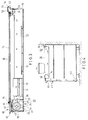
- FIG. 1 shows an exploded view of a heat radiating device of a first preferred embodiment of the present invention.
- FIG. 2 shows a perspective view of the first preferred embodiment of the present invention.
- FIG. 3 is a sectional schematic view of the heat radiating device of the first preferred embodiment of the present invention.
- FIG. 4 is a schematic view showing the way that the heat is radiated by the heat radiating device of the induction heater housed in a kitchen cabinet, according to the present invention.
- FIG. 5 shows an exploded view of a heat radiating device of a second preferred embodiment of the present invention.
- FIG. 6 is a schematic view showing the way that the heat is radiated by the heat radiating device of the induction heater housed in a kitchen cabinet, according to a third preferred embodiment of the present invention.
- a heat radiating device of an induction heater embodied in the present invention is shown to comprise a bottom housing 10 provided therein with an air admitting and heat radiating unit 20 and provided thereon with a receiving portion 30 which in turn is provided at the front end thereof with a face plate unit 40 having at the rear end thereof an air ventilating unit 50.
- the bottom housing 10 of rectangular construction has a bottom plate 11 provided thereon with a plurality of circuit boards 12 and heat radiating pieces 13, as shown in FIG. 3.
- the bottom plate 11 is provided at the front end thereof with a predetermined number of air admitting holes 14 and retaining holes 13. Mounted on the air admitting holes 14 is the air admitting unit 20.
- the air admitting unit 20 is composed of a fan seat 22 and a motor 23 for driving a fan 24 mounted on the fan seat 22 which is provided at the bottom thereof with a predetermined number of tenons 25.
- the fan 24 is received in a receiving space 26 having an air outlet 28, as shown in FIG. 3.
- the receiving portion 30 comprises mainly a rectangular receiving plate 31 of a ceramic or heat-resisting material and having two frame strips 32 and 33 capable of being fastened to the two side plates 16 and 17 of the bottom housing 10 by means of screws (not shown in the drawings.)
- the face plate unit 40 comprises mainly a plastic housing provided at the top thereof with an operation face plate 41 having a plurality of operating keys and further provided at the front thereof with a front frame 42 for fitting into the upper edge of the bottom housing 10.
- the face plate unit 40 is further provided with a retaining plate 43 extending downwards from the bottom thereof.
- the retaining plate 43 is engageable securely with a front end plate 18 of the bottom housing 10.
- the air ventilating unit 50 is located behind the receiving portion 30 and composed of a ventilating seat 51 and a horizontal frame 52 engageable with a rear end plate 19 of the bottom housing 10.
- the ventilating seat 51 has an inverted L-shaped air duct 55 with an air ventilating hole 56 located above the bottom housing 10 and facing horizontally the back of the heater to prevent the entry of a foreign object or the liquid into the inside of the heater.
- the tenons 25 of the fan seat 22 of the heat radiating unit 20 engage respectively with the retaining holes 13 of the bottom plate 11.
- the fan 24 is aligned with the air admitting hole 14.
- the face plate unit 40 is fastened over the heat radiating unit 20 such that the front horizontal frame 42 engages the inner edge of the front end plate 18 of the bottom housing 10.
- the front edge 34 of the receiving portion engages the rear edge 44 of the face plate 41.
- the ventilating seat 51 has an insertion frame 53 engaging the rear end plate 19 of the bottom housing 10 such that the receiving portion 30, the face plate unit 40 and the ventilating seat 51 is fastened to the bottom housing 10.
- the heat radiating device of the induction heater is mounted at the top portion of a kitchen cabinet 60.
- the air is let in via the inlets 61 and 62.
- the air is the blown by the fan 24 to enter the interior of the heater via the air admitting holes 14 and the air outlet 28, as indicated by the arrows in the drawings.
- the air is then let out via the ventilating hole 56 of the ventilating seat 51.
- another preferred embodiment of the present invention is similar in construction to the first preferred embodiment of the present invention described above, with the difference being that the air admitting unit 70 is provided with a square fan 71 fastened to the air admitting holes 14.
- the air outlet 72 of the fan 71 faces the interior of the heater for radiating the heat.
- the fan 71 is different in structure from the fan 24 of the first preferred embodiment and can be made and installed easily.
- the third preferred embodiment of the present invention is shown to comprise a housing 10, a receiving portion 30 and a ventilating seat 51 and is intended for use in conjunction with an oven.
- a kitchen cabinet 60 is provided with an oven 64.
- a fan 80 is set up at the rear end of the bottom housing 10. In other words, the fan 80 is located at the end contiguous to the ventilating seat 51, which is provided horizontally with a ventilating hole 56.
- the fan 80 has an air inlet 81 in communication with the ventilating hole 56.
- the fan 80 further has an air outlet 82 facing a heat radiating plate 13.
- the bottom plate 11 is provided with two heat-radiating holes 83 and 84.
- the air which is sucked in via the ventilating hole 56 of the ventilating seat 51 by the fan is blown toward the heat-radiating plate 13 before entering the kitchen cabinet 60 via the heat-radiating holes 83 and 84.
- the air is then let out via another heat-radiating holes 85 and 86.
- the three preferred embodiments of the present invention are provided respectively with a ventilating seat 51 having a ventilating hole 56 located horizontally at a level slightly higher than the surface of the kitchen cabinet.
- the air is admitted and exhausted in a horizontal direction, thereby preventing the entry of the overflowing liquid into the inside of the heater.
Landscapes
- Engineering & Computer Science (AREA)
- Chemical & Material Sciences (AREA)
- Combustion & Propulsion (AREA)
- Mechanical Engineering (AREA)
- General Engineering & Computer Science (AREA)
- Physics & Mathematics (AREA)
- Electromagnetism (AREA)
- Induction Heating Cooking Devices (AREA)
- Electric Stoves And Ranges (AREA)
Priority Applications (2)
| Application Number | Priority Date | Filing Date | Title |
|---|---|---|---|
| EP94105115A EP0675672A1 (de) | 1994-03-31 | 1994-03-31 | Wärmeausstrahllvorrichtung für Induktionsheizer |
| US08/223,691 US5446268A (en) | 1994-03-31 | 1994-04-06 | Heat radiating device of induction heater |
Applications Claiming Priority (2)
| Application Number | Priority Date | Filing Date | Title |
|---|---|---|---|
| EP94105115A EP0675672A1 (de) | 1994-03-31 | 1994-03-31 | Wärmeausstrahllvorrichtung für Induktionsheizer |
| US08/223,691 US5446268A (en) | 1994-03-31 | 1994-04-06 | Heat radiating device of induction heater |
Publications (1)
| Publication Number | Publication Date |
|---|---|
| EP0675672A1 true EP0675672A1 (de) | 1995-10-04 |
Family
ID=26135557
Family Applications (1)
| Application Number | Title | Priority Date | Filing Date |
|---|---|---|---|
| EP94105115A Withdrawn EP0675672A1 (de) | 1994-03-31 | 1994-03-31 | Wärmeausstrahllvorrichtung für Induktionsheizer |
Country Status (2)
| Country | Link |
|---|---|
| US (1) | US5446268A (de) |
| EP (1) | EP0675672A1 (de) |
Cited By (12)
| Publication number | Priority date | Publication date | Assignee | Title |
|---|---|---|---|---|
| EP0921711A1 (de) * | 1997-11-19 | 1999-06-09 | Therma Grossküchen Produktion AG | Vollflächen-Induktionskochherd |
| EP0951203A2 (de) * | 1998-04-17 | 1999-10-20 | BSH Bosch und Siemens Hausgeräte GmbH | Anordnung mit Backofen und Kochfeld |
| ES2177408A1 (es) * | 1999-07-29 | 2002-12-01 | Bsh Bosch Siemens Hausgeraete | Zona de coccion por induccion con tentilador de refrigeracion. |
| EP1734309A1 (de) * | 2004-03-16 | 2006-12-20 | Matsushita Electric Industries Co., Ltd. | Eingebaute heizkochvorrichtung |
| WO2009010538A1 (de) * | 2007-07-17 | 2009-01-22 | BSH Bosch und Siemens Hausgeräte GmbH | Kochfeld und verfahren zum herstellen eines kochfelds |
| ES2328993A1 (es) * | 2006-07-18 | 2009-11-19 | Bsh Electrodomesticos España, S.A. | Dispositivo protector de una unidad calefactora. |
| ES2338730A1 (es) * | 2007-09-25 | 2010-05-11 | Bsh Electrodomesticos España, S.A. | Aparato de coccion a gas con un carril. |
| FR2952502A1 (fr) * | 2009-11-12 | 2011-05-13 | Fagorbrandt Sas | Table de cuisson a induction |
| EP2531003A3 (de) * | 2011-06-02 | 2013-01-16 | General Electric Company | Kühlkit für ein Induktionskochfeld |
| EP2790467A1 (de) * | 2013-04-08 | 2014-10-15 | Electrolux Appliances Aktiebolag | Induktionskochfeld und Arbeitsoberseitenanordnung |
| ES2633599A1 (es) * | 2016-03-21 | 2017-09-22 | Bsh Electrodomésticos España, S.A. | Dispositivo de campo de cocción |
| EP2696144A3 (de) * | 2012-07-11 | 2017-12-13 | Whirlpool Corporation | Belüftungssystem für Induktionskochfeld |
Families Citing this family (28)
| Publication number | Priority date | Publication date | Assignee | Title |
|---|---|---|---|---|
| US6444958B1 (en) * | 2000-09-26 | 2002-09-03 | General Electric Company | Cooking appliance and method of cooling the same |
| US7148452B2 (en) * | 2001-04-03 | 2006-12-12 | Emerson Electric Co. | Heat sink for printed circuit board components |
| US7049552B2 (en) * | 2004-06-04 | 2006-05-23 | Maytag Corporation | Ventilation system for a cooking appliance |
| JP4082402B2 (ja) * | 2004-10-19 | 2008-04-30 | 松下電器産業株式会社 | タッチキーを用いた電磁調理器 |
| KR101058688B1 (ko) * | 2004-11-10 | 2011-08-22 | 파나소닉 주식회사 | 내장형 가열 조리기 및 그 가열 조리기가 조립되는 주방조리대 |
| US7960673B2 (en) * | 2005-01-29 | 2011-06-14 | Li George T C | Portable electric grill |
| US8884197B2 (en) * | 2007-02-03 | 2014-11-11 | Western Industries, Inc. | Induction cook top with heat management system |
| US8872077B2 (en) * | 2005-08-01 | 2014-10-28 | Western Industries, Inc. | Low profile induction cook top with heat management system |
| KR20080025603A (ko) * | 2006-09-18 | 2008-03-21 | 삼성전자주식회사 | 가열조리기 및 그 제어방법 |
| WO2008082074A1 (en) * | 2006-12-29 | 2008-07-10 | Lg Electronics Inc. | Built-in cooking appliance |
| MX2009007142A (es) * | 2006-12-29 | 2009-07-09 | Lg Electronics Inc | Electrodomestico para cocinar integrado y aparato para la instalacion del mismo. |
| WO2008084918A1 (en) * | 2007-01-08 | 2008-07-17 | Lg Electronics Inc. | Built-in cooking appliance |
| US7732740B2 (en) * | 2007-04-24 | 2010-06-08 | Sung Hsien Shan | Casing for electric stoves |
| US8253076B2 (en) * | 2007-10-29 | 2012-08-28 | Smiths Medical Asd, Inc. | Respiratory system heater unit |
| US7950383B2 (en) * | 2008-04-16 | 2011-05-31 | Electrolux Home Products, Inc. | Ventilating kitchen range subframe |
| KR101623975B1 (ko) * | 2009-05-11 | 2016-05-24 | 엘지전자 주식회사 | 조리기기 |
| US9402284B1 (en) * | 2009-10-08 | 2016-07-26 | Spring (U.S.A.) Corporation | Reconfigurable induction cooktops |
| USD708003S1 (en) | 2010-12-27 | 2014-07-01 | Western Industries, Inc. | Cook top |
| USD694569S1 (en) | 2011-12-30 | 2013-12-03 | Western Industries, Inc. | Cook top |
| US9777930B2 (en) | 2012-06-05 | 2017-10-03 | Western Industries, Inc. | Downdraft that is telescoping |
| US9897329B2 (en) | 2012-06-08 | 2018-02-20 | Western Industries, Inc. | Cooktop with downdraft ventilator |
| JP6238852B2 (ja) * | 2014-08-04 | 2017-11-29 | 三菱電機株式会社 | 電磁誘導加熱調理器 |
| KR101851862B1 (ko) * | 2016-08-26 | 2018-04-24 | 엘지전자 주식회사 | 벤트를 구비하는 조리기기 |
| EP3396255B1 (de) * | 2017-04-26 | 2023-06-07 | Electrolux Appliances Aktiebolag | Induktionskochfeld mit integrierter saugzughaube |
| US10993292B2 (en) * | 2017-10-23 | 2021-04-27 | Whirlpool Corporation | System and method for tuning an induction circuit |
| CN108829213A (zh) * | 2018-05-31 | 2018-11-16 | 合肥利元杰信息科技有限公司 | 一种旋转式计算机散热装置 |
| JP7097756B2 (ja) * | 2018-06-18 | 2022-07-08 | 三菱電機株式会社 | 加熱調理器 |
| JP2020067251A (ja) * | 2018-10-25 | 2020-04-30 | 株式会社ハーマン | 加熱調理器 |
Citations (6)
| Publication number | Priority date | Publication date | Assignee | Title |
|---|---|---|---|---|
| FR2340513A1 (fr) * | 1976-02-03 | 1977-09-02 | Orega Electro Mecanique | Plaque de cuisson utilisant le chauffage par induction, et cuisiniere comportant une telle plaque |
| EP0067235A1 (de) * | 1980-12-26 | 1982-12-22 | Matsushita Electric Industrial Co., Ltd. | Kochgerät mit induktionshitze |
| US4415788A (en) * | 1981-06-08 | 1983-11-15 | Jenn-Air Corporation | Induction cartridge |
| EP0376791A1 (de) * | 1988-12-27 | 1990-07-04 | Compagnie Europeenne Pour L'equipement Menager "Cepem" | Träger für Regelorgane an Haushaltsgeräten |
| JPH02234384A (ja) * | 1989-03-07 | 1990-09-17 | Matsushita Electric Ind Co Ltd | 誘導加熱調理器 |
| EP0561219A1 (de) * | 1992-03-14 | 1993-09-22 | E.G.O. Elektro-Geräte Blanc und Fischer GmbH & Co. KG | Induktive Kochstellenbeheizung |
Family Cites Families (5)
| Publication number | Priority date | Publication date | Assignee | Title |
|---|---|---|---|---|
| US4549052A (en) * | 1984-01-12 | 1985-10-22 | The Maytag Company | Cooling system for an induction cooking cartridge |
| JPS63148595A (ja) * | 1986-12-11 | 1988-06-21 | 松下電器産業株式会社 | 加熱調理装置 |
| JPH0711984B2 (ja) * | 1987-10-16 | 1995-02-08 | 松下電器産業株式会社 | 誘導加熱調理器 |
| FR2635852B1 (fr) * | 1988-08-29 | 1994-09-16 | Samsung Electronics Co Ltd | Appareil electronique de cuisson du type modulaire |
| JP3006175B2 (ja) * | 1991-07-08 | 2000-02-07 | 松下電器産業株式会社 | 組み込み式加熱調理器 |
-
1994
- 1994-03-31 EP EP94105115A patent/EP0675672A1/de not_active Withdrawn
- 1994-04-06 US US08/223,691 patent/US5446268A/en not_active Expired - Fee Related
Patent Citations (6)
| Publication number | Priority date | Publication date | Assignee | Title |
|---|---|---|---|---|
| FR2340513A1 (fr) * | 1976-02-03 | 1977-09-02 | Orega Electro Mecanique | Plaque de cuisson utilisant le chauffage par induction, et cuisiniere comportant une telle plaque |
| EP0067235A1 (de) * | 1980-12-26 | 1982-12-22 | Matsushita Electric Industrial Co., Ltd. | Kochgerät mit induktionshitze |
| US4415788A (en) * | 1981-06-08 | 1983-11-15 | Jenn-Air Corporation | Induction cartridge |
| EP0376791A1 (de) * | 1988-12-27 | 1990-07-04 | Compagnie Europeenne Pour L'equipement Menager "Cepem" | Träger für Regelorgane an Haushaltsgeräten |
| JPH02234384A (ja) * | 1989-03-07 | 1990-09-17 | Matsushita Electric Ind Co Ltd | 誘導加熱調理器 |
| EP0561219A1 (de) * | 1992-03-14 | 1993-09-22 | E.G.O. Elektro-Geräte Blanc und Fischer GmbH & Co. KG | Induktive Kochstellenbeheizung |
Non-Patent Citations (1)
| Title |
|---|
| PATENT ABSTRACTS OF JAPAN vol. 14, no. 546 (E - 1008) 4 December 1990 (1990-12-04) * |
Cited By (23)
| Publication number | Priority date | Publication date | Assignee | Title |
|---|---|---|---|---|
| EP0921711A1 (de) * | 1997-11-19 | 1999-06-09 | Therma Grossküchen Produktion AG | Vollflächen-Induktionskochherd |
| EP0951203A2 (de) * | 1998-04-17 | 1999-10-20 | BSH Bosch und Siemens Hausgeräte GmbH | Anordnung mit Backofen und Kochfeld |
| DE19817197A1 (de) * | 1998-04-17 | 1999-10-21 | Bsh Bosch Siemens Hausgeraete | Anordnung mit Backofen und Kochfeld |
| DE19817197C2 (de) * | 1998-04-17 | 2000-07-06 | Bsh Bosch Siemens Hausgeraete | Anordnung mit Backofen und Kochfeld |
| EP0951203A3 (de) * | 1998-04-17 | 2000-11-29 | BSH Bosch und Siemens Hausgeräte GmbH | Anordnung mit Backofen und Kochfeld |
| ES2177408A1 (es) * | 1999-07-29 | 2002-12-01 | Bsh Bosch Siemens Hausgeraete | Zona de coccion por induccion con tentilador de refrigeracion. |
| EP1734309A1 (de) * | 2004-03-16 | 2006-12-20 | Matsushita Electric Industries Co., Ltd. | Eingebaute heizkochvorrichtung |
| EP1734309A4 (de) * | 2004-03-16 | 2008-06-11 | Matsushita Electric Ind Co Ltd | Eingebaute heizkochvorrichtung |
| US7533666B2 (en) | 2004-03-16 | 2009-05-19 | Panasonic Corporation | Built-in type heating cooking device |
| ES2328993A1 (es) * | 2006-07-18 | 2009-11-19 | Bsh Electrodomesticos España, S.A. | Dispositivo protector de una unidad calefactora. |
| ES2324448A1 (es) * | 2007-07-17 | 2009-08-06 | Bsh Electrodomesticos España, S.A. | Campo de coccion por induccion y procedimiento para la fabricacion de un campo de coccion por induccion. |
| WO2009010538A1 (de) * | 2007-07-17 | 2009-01-22 | BSH Bosch und Siemens Hausgeräte GmbH | Kochfeld und verfahren zum herstellen eines kochfelds |
| ES2338730A1 (es) * | 2007-09-25 | 2010-05-11 | Bsh Electrodomesticos España, S.A. | Aparato de coccion a gas con un carril. |
| FR2952502A1 (fr) * | 2009-11-12 | 2011-05-13 | Fagorbrandt Sas | Table de cuisson a induction |
| EP2531003A3 (de) * | 2011-06-02 | 2013-01-16 | General Electric Company | Kühlkit für ein Induktionskochfeld |
| US9125244B2 (en) | 2011-06-02 | 2015-09-01 | General Electric Company | Induction cooktop cooling kit |
| AU2012203187B2 (en) * | 2011-06-02 | 2015-10-29 | Haier Us Appliance Solutions, Inc. | Induction cooktop cooling kit |
| EP2696144A3 (de) * | 2012-07-11 | 2017-12-13 | Whirlpool Corporation | Belüftungssystem für Induktionskochfeld |
| EP2790467A1 (de) * | 2013-04-08 | 2014-10-15 | Electrolux Appliances Aktiebolag | Induktionskochfeld und Arbeitsoberseitenanordnung |
| WO2014166696A1 (en) * | 2013-04-08 | 2014-10-16 | Electrolux Appliances Aktiebolag | Induction cooker hob and worktop arrangement |
| CN105103653A (zh) * | 2013-04-08 | 2015-11-25 | 伊莱克斯家用电器股份公司 | 感应烹饪灶具和工作台安排 |
| CN105103653B (zh) * | 2013-04-08 | 2019-07-30 | 伊莱克斯家用电器股份公司 | 感应烹饪灶具和工作台安排 |
| ES2633599A1 (es) * | 2016-03-21 | 2017-09-22 | Bsh Electrodomésticos España, S.A. | Dispositivo de campo de cocción |
Also Published As
| Publication number | Publication date |
|---|---|
| US5446268A (en) | 1995-08-29 |
Similar Documents
| Publication | Publication Date | Title |
|---|---|---|
| EP0675672A1 (de) | Wärmeausstrahllvorrichtung für Induktionsheizer | |
| US6621058B1 (en) | Wall-mounted microwave oven with air curtain guide | |
| EP1211914B1 (de) | Heizvorrichtung versehen mit einer Heizquelle unterschiedlicher von Mikrowellen bei einem Mikrowellenofen | |
| US6797930B2 (en) | Wall-mounted type microwave oven | |
| US6600139B2 (en) | Appliance control protection apparatus | |
| JP2000323878A (ja) | 電子機器の冷却構造 | |
| US20060011622A1 (en) | Microwave having a top vent | |
| EP1243164B1 (de) | Einbau-mikrowellenofen | |
| EP0917408A3 (de) | Struktur fur die Luftzirkulation fur einem Mikrowellenherd | |
| US7019272B2 (en) | Wall mounted microwave oven having an exhaust ventilation system | |
| EP1220574B1 (de) | Elektrischer Ausrüstungsraum bei Mikrowellenöfen | |
| JP2002039546A (ja) | 加熱調理器 | |
| KR20000032363A (ko) | 공기조화기의 흡음재 | |
| JP3735810B2 (ja) | 加熱調理器 | |
| KR100320669B1 (ko) | 가열조리기 | |
| JP2966658B2 (ja) | 加熱調理器 | |
| JPH03114179A (ja) | 誘導加熱調理器 | |
| US11009235B2 (en) | Domestic kitchen appliance with sidewall cooling | |
| JP2004172137A (ja) | 誘導加熱調理器 | |
| KR19980043791A (ko) | 전자레인지의 공기흐름장치 | |
| KR20040021906A (ko) | 적외선 버너를 갖는 가스오븐레인지의 공냉시스템 | |
| JPH05340542A (ja) | 加熱調理器 | |
| KR930000329Y1 (ko) | 오버더 레인지의 에어닥트 장치 | |
| KR100289118B1 (ko) | 전자렌지 | |
| KR200147231Y1 (ko) | 전자렌지의 쟁반모터 브래킷 |
Legal Events
| Date | Code | Title | Description |
|---|---|---|---|
| PUAI | Public reference made under article 153(3) epc to a published international application that has entered the european phase |
Free format text: ORIGINAL CODE: 0009012 |
|
| 17P | Request for examination filed |
Effective date: 19950810 |
|
| AK | Designated contracting states |
Kind code of ref document: A1 Designated state(s): AT BE CH DE DK ES FR GB GR IE IT LI NL PT SE |
|
| RAP1 | Party data changed (applicant data changed or rights of an application transferred) |
Owner name: HUANG, WEN-LIANG |
|
| STAA | Information on the status of an ep patent application or granted ep patent |
Free format text: STATUS: THE APPLICATION IS DEEMED TO BE WITHDRAWN |
|
| 18D | Application deemed to be withdrawn |
Effective date: 19991001 |