EP3223585B2 - Plaque de cuisson - Google Patents
Plaque de cuisson Download PDFInfo
- Publication number
- EP3223585B2 EP3223585B2 EP17157771.1A EP17157771A EP3223585B2 EP 3223585 B2 EP3223585 B2 EP 3223585B2 EP 17157771 A EP17157771 A EP 17157771A EP 3223585 B2 EP3223585 B2 EP 3223585B2
- Authority
- EP
- European Patent Office
- Prior art keywords
- unit
- housing unit
- housing
- assembled state
- hob
- Prior art date
- Legal status (The legal status is an assumption and is not a legal conclusion. Google has not performed a legal analysis and makes no representation as to the accuracy of the status listed.)
- Active
Links
Images


Classifications
-
- F—MECHANICAL ENGINEERING; LIGHTING; HEATING; WEAPONS; BLASTING
- F24—HEATING; RANGES; VENTILATING
- F24C—DOMESTIC STOVES OR RANGES ; DETAILS OF DOMESTIC STOVES OR RANGES, OF GENERAL APPLICATION
- F24C15/00—Details
- F24C15/20—Removing cooking fumes
- F24C15/2042—Devices for removing cooking fumes structurally associated with a cooking range e.g. downdraft
-
- F—MECHANICAL ENGINEERING; LIGHTING; HEATING; WEAPONS; BLASTING
- F24—HEATING; RANGES; VENTILATING
- F24C—DOMESTIC STOVES OR RANGES ; DETAILS OF DOMESTIC STOVES OR RANGES, OF GENERAL APPLICATION
- F24C15/00—Details
- F24C15/10—Tops, e.g. hot plates; Rings
- F24C15/102—Tops, e.g. hot plates; Rings electrically heated
-
- H—ELECTRICITY
- H05—ELECTRIC TECHNIQUES NOT OTHERWISE PROVIDED FOR
- H05B—ELECTRIC HEATING; ELECTRIC LIGHT SOURCES NOT OTHERWISE PROVIDED FOR; CIRCUIT ARRANGEMENTS FOR ELECTRIC LIGHT SOURCES, IN GENERAL
- H05B6/00—Heating by electric, magnetic or electromagnetic fields
- H05B6/02—Induction heating
- H05B6/10—Induction heating apparatus, other than furnaces, for specific applications
- H05B6/12—Cooking devices
- H05B6/1209—Cooking devices induction cooking plates or the like and devices to be used in combination with them
Definitions
- the invention relates to a hob device according to the preamble of patent claim 1.
- a hotplate which contains a hob device as a subassembly.
- a hob device is already known which has a housing unit and a web-like reinforcement unit.
- the reinforcement unit is fastened to a base of the housing unit in an assembled state and is intended to reinforce the housing unit.
- the object of the invention is in particular to provide a generic device with improved properties with regard to high stability. The object is achieved according to the invention by the features of patent claim 1, while advantageous embodiments and further developments of the invention can be taken from the subclaims.
- the invention is based on a hob device, in particular an induction hob device, with a housing unit and with at least one web-like reinforcement unit, which is provided for reinforcing the housing unit and is permanently attached to the housing unit without tools, at least in an assembled state.
- the reinforcement unit has at least one fastening element which, in the assembled state, is provided for fastening at least to one side wall of the housing unit, wherein the reinforcement unit has at least one further fastening element which, in the assembled state, is provided for fastening at least to another side wall of the housing unit.
- a "cooktop device” is to be understood in particular as at least one part, in particular a subassembly, of a cooktop, in particular an induction cooktop, wherein in particular accessory units for the cooktop can also be included.
- the cooktop device can also comprise the entire cooktop, in particular the entire induction cooktop.
- a "housing unit” is to be understood in particular as a unit which, in the assembled state, is provided to at least partially delimit and/or define at least one receiving space, in particular designed as a cavity, for receiving and/or storing at least one component.
- the component could, for example, be at least one heating unit and/or a control unit and/or a supply unit and/or a user interface.
- the housing unit and a hob plate, in particular together at least essentially delimit the receiving space.
- the receiving space is in particular designed as a hollow space.
- the housing unit in particular absorbs a weight force of components at least to a large extent and/or transfers the weight force to at least one further unit, such as the hob plate.
- the hob device in particular has the hob plate.
- the housing unit is advantageously designed as an outer housing unit and in particular together with the hob plate defines an outer hob housing at least essentially.
- a "web-like" reinforcement unit is to be understood in particular as a unit which has a longitudinal extension which is at least 4 times, in particular at least 5 times, advantageously at least 7 times, particularly advantageously at least 10 times and preferably at least 20 times as large as a smallest transverse extension of the reinforcement unit and in particular additionally as a second smallest transverse extension of the reinforcement unit.
- the web-like reinforcement unit has at least one transverse extension when viewed from a projection in a plane which is aligned in particular parallel to a main extension plane of the housing unit, which is a maximum of 25%, in particular a maximum of 20%, advantageously a maximum of 15%, particularly advantageously a maximum of 10% and preferably a maximum of 5% of a longitudinal extension of the reinforcement unit.
- a "longitudinal extension" of an object is to be understood in particular as an extension of the object in a longitudinal extension direction of the object.
- a “longitudinal extension direction” of an object is to be understood in particular as a direction which is aligned parallel to a longest side of a smallest imaginary geometric cuboid which just completely encloses the object.
- extension of an object is to be understood in particular as a maximum distance between two points of a vertical projection of the object onto a plane.
- the smallest transverse extension of the reinforcement unit and the second smallest transverse extension of the reinforcement unit are in particular aligned perpendicular to the longitudinal extension of the reinforcement unit.
- the smallest transverse extension of the reinforcement unit and the second smallest transverse extension of the reinforcement unit are aligned perpendicular to one another.
- a "main extension plane" of an object is to be understood in particular as a plane which is parallel to a largest side surface of a smallest imaginary geometric cuboid which just completely encloses the object and in particular runs through the center of the cuboid.
- the reinforcement unit is in particular designed differently from the housing unit and in particular can be moved relative to the housing unit in at least one disassembled state.
- the reinforcement unit is intended to divide the receiving space at least partially delimited by the housing unit into at least two subspaces which are arranged next to one another in particular in a horizontal direction.
- the horizontal direction is in particular aligned parallel to a main extension plane of the housing unit and/or perpendicular to a direction of gravity.
- the reinforcement unit is preferably provided to at least substantially prevent deformation of the housing unit when an external force acts on the housing unit.
- the external force could in particular have a value of at least 50 N, in particular of at least 75 N, advantageously of at least 100 N, particularly advantageously of at least 125 N, preferably of at least 150 N and particularly preferably of at least 175 N.
- the external force could be caused and/or induced by a trigger unit.
- the reinforcement unit is attached to the housing unit by means of a connection that can only be released using a tool.
- a "fastening element” is to be understood as an element that is provided to fasten the reinforcement unit at least to the side wall of the housing unit by means of a connection that can only be released using a tool.
- the fastening of the reinforcement unit to the side wall of the housing unit by the fastening element differs from a connection that can be released without tools.
- the fastening element is in particular intended to fasten the reinforcement unit in the assembled state to the side wall of the housing unit by means of a force-fitting and/or by means of a form-fitting and/or by means of a material-fitting connection.
- a "side wall" of the housing unit is to be understood in particular as a unit which is intended to at least substantially delimit the housing unit in the assembled state at least in a horizontal direction aligned parallel to the main extension plane of the housing unit and/or which is intended to form a main delimitation of the housing unit in the horizontal direction in the assembled state.
- the side wall could be intended to delimit the housing unit in addition to a delimitation in the horizontal direction at least partially in a vertical direction aligned at least substantially perpendicular to the main extension plane of the housing unit.
- the side wall of the housing unit is in particular a lateral delimitation of the housing unit and in particular has a main extension plane which is at least substantially perpendicular to a main extension plane of the housing unit.
- a normal vector to the main extension plane of the side wall is aligned in an installed position in particular at least substantially perpendicular to a direction of gravity.
- the vertical direction is aligned in particular perpendicular to the main extension plane of the housing unit and/or parallel to a direction of gravity.
- Provided is to be understood in particular as specially designed and/or equipped.
- the fact that an object is provided for a specific function is to be understood in particular as meaning that the object fulfills and/or carries out this specific function in at least one application and/or operating state.
- the housing unit can retain its original shape in the event of heavy loads acting on the housing unit.
- the reinforcement unit attached at least to the side wall can in particular divide the longitudinal extent of the housing unit into smaller sub-areas. This can in particular prevent deformation of the housing unit, which in particular can prevent interactions with adjacent kitchen components, which could be caused by deformation of the housing unit, for example.
- a correct positioning of components of the hob device, such as at least one heating unit and/or a user interface, in particular relative to the hob plate can be ensured and their correct function can be guaranteed.
- the fastening element could be fastened to the side wall of the housing unit in the assembled state by means of a screw connection.
- the fastening element is fastened to the side wall of the housing unit in the assembled state by means of a connection other than a material connection.
- the fastening element is fastened to the side wall of the housing unit in the assembled state by means of at least one rivet connection. This makes it possible to achieve a particularly stable design.
- the reinforcement unit has at least one further fastening element which, in the assembled state, is provided for fastening at least to a further side wall of the housing unit.
- the further fastening element could be provided for fastening to a further side wall adjacent to the side wall, which could in particular be aligned at least substantially perpendicular to the side wall.
- the further fastening element could in particular form an at least substantially triangular shape together with the side wall and with the further side wall when viewed in a projection in a plane which is aligned in particular parallel to a main extension plane of the housing unit.
- the reinforcement unit has at least one further fastening element which, in the assembled state, is provided for fastening at least to a further side wall of the housing unit opposite the side wall.
- the further fastening element could be fastened to the further side wall of the housing unit by means of a screw connection in the assembled state.
- the further fastening element is fastened to the further side wall of the housing unit in the assembled state by means of a connection other than a material connection.
- the further fastening element is fastened in the assembled state to the further side wall of the housing unit by means of at least one rivet connection.
- a longitudinal extension direction of the reinforcement unit is in particular aligned at least substantially perpendicular to a main extension plane of the side wall and/or, in particular and, to a main extension plane of the further side wall.
- the reinforcement unit forms at least one reinforcement strut, which is provided for reinforcing the housing unit.
- the housing unit can in particular be divided into several subsections and thus in particular optimally stabilized.
- the reinforcement unit has at least one support element which, in the assembled state, is provided for fastening at least to a base of the housing unit.
- the support element could be fastened to the base of the housing unit in the assembled state by means of a screw connection.
- the support element is fastened to the base of the housing unit in the assembled state by means of a connection other than a material connection.
- the support element is fastened to the base of the housing unit in the assembled state by means of at least one rivet connection.
- the support element has in particular a main extension plane which is aligned in particular at least substantially perpendicular to a longitudinal extension direction of the reinforcement unit and/or at least substantially parallel to a main extension plane of the housing unit.
- a “base” of the housing unit is to be understood in particular as a unit which is provided to at least substantially delimit the housing unit in the assembled state at least in the vertical direction and/or to form a main delimitation of the housing unit in the vertical direction in the assembled state.
- the base in an installed position, the base forms a wall facing a substrate and/or a wall of the housing unit that delimits the housing unit, in particular the receiving space delimited by the housing unit.
- the base is in particular intended for setting up at least one component.
- the base in particular has a main extension plane, which is in particular aligned at least substantially parallel to a main extension plane of the hob plate and/or at least substantially parallel to a main extension plane of the housing unit. This makes it possible in particular to reinforce the housing unit in a plane that is aligned at least substantially perpendicular to the side wall.
- the reinforcement unit has at least one support element which is intended to provide at least one support surface for at least one room divider element in the assembled state.
- the hob device has the room divider element.
- a "room divider element" is to be understood in particular as an element which is intended to divide at least one room, in particular at least the receiving room, into at least two sub-rooms in the assembled state.
- the room divider element is designed as a plate.
- the room divider element is preferably arranged between at least one heating unit and at least one electronic unit, such as a control unit and/or a supply unit and/or hob electronics.
- the room divider element is advantageously intended to divide the room, in particular the receiving room, into large areas.
- the room divider element has in particular a surface area of at least 0.1 m 2 , in particular of at least 0.2 m 2 , advantageously of at least 0.3 m 2 , particularly advantageously of at least 0.35 m 2 and preferably of at least 0.4 m 2 .
- the room divider element has a longitudinal extent of at least 30 cm, in particular of at least 40 cm, advantageously of at least 50 cm, particularly advantageously of at least 60 cm and preferably of at least 80 cm.
- the room divider element has in particular a transverse extent of at least 30 cm, in particular of at least 40 cm, advantageously of at least 50 cm, particularly advantageously of at least 55 cm and preferably of at least 60 cm.
- the room divider element is in particular designed as a shielding element which is in particular intended to shield at least one electronic unit, such as a control unit, from electromagnetic radiation caused by at least one heating unit, in particular thermal radiation and/or magnetic fields and/or electrical fields.
- the room divider element consists at least to a large extent of a non-magnetic and electrically conductive material, in particular of metal and advantageously of aluminum. "At least to a large extent” is to be understood in particular as a proportion of at least 70%, in particular of at least 80%, advantageously of at least 90% and preferably of at least 95%. This means that additional components for supporting the room divider element can be dispensed with and/or a cost-effective design can be achieved.
- a complete stabilization of the housing unit can be achieved.
- a position of at least one heating unit arranged above the room divider element can be stabilized and/or the heating unit can be held in a designated position, which in particular can ensure optimal heating of cooking utensils placed thereon.
- the reinforcement unit has at least one position securing element which is provided to secure a position of an inner housing unit relative to the housing unit in the assembled state.
- the position securing element is in particular provided to prevent movement of the inner housing unit relative to the housing unit at least in the vertical direction in the assembled state. to avoid.
- the reinforcement unit is provided to clamp at least part of the inner housing unit between the position securing element and the housing unit in the assembled state.
- the hob device has the inner housing unit.
- An "inner housing unit" is to be understood in particular as a unit which in the assembled state is at least largely hidden from an operator and/or inaccessible and which is provided in particular to supplement and/or support the housing unit.
- the inner housing unit could, for example, be provided to at least substantially electrically insulate electrical and/or electronic hob components from the housing unit, which could in particular be designed to be electrically conductive, wherein the inner housing unit could in particular be made of at least one electrically insulating material.
- the inner housing unit In the assembled state, the inner housing unit is in particular at least largely surrounded by the housing unit. This can in particular prevent movement of the inner housing unit relative to the housing unit, in particular when transporting the hob device.
- the reinforcement unit can take on several functions simultaneously, which in particular means that additional components and/or measures for securing a position of the inner housing unit can be dispensed with.
- the reinforcement unit is formed in one piece.
- the reinforcement unit has at least one metallic material and is advantageously formed at least to a large extent from at least one metallic material.
- the metallic material could be, for example, a sheet metal, in particular a stamped and bent sheet metal, and/or a steel, in particular a galvanized steel.
- the term "in one piece" is to be understood in particular as at least materially connected, for example by a welding process, an adhesive process, an injection molding process and/or another process that appears to be useful to a person skilled in the art, and/or advantageously formed in one piece, for example by production from a cast and/or by production using a single or multi-component injection molding process and advantageously from a single blank. This makes it possible to achieve a high level of stability in particular.
- the reinforcement unit in the assembled state is arranged in particular in a close area and advantageously in an edge area of a housing recess of the housing unit and is provided for reinforcing the housing unit in an area of a housing recess of the housing unit.
- the housing recess is arranged in an area around a center point and/or center of gravity of the base of the housing unit.
- a geometric center of gravity of the housing recess and a center of gravity of the base of the housing unit are in particular at least substantially identical.
- the area of the housing recess in particular comprises the housing recess and a close area of the housing recess.
- the area of the housing recess is in particular delimited by an imaginary line which has a distance of a maximum of 85%, in particular a maximum of 80%, advantageously a maximum of 75%, particularly advantageously a maximum of 70% and preferably a maximum of 60% of a longitudinal extension and/or a transverse extension of the housing recess from a geometric center of gravity of the housing recess.
- the reinforcement unit could, for example, at least partially bridge the housing recess. Alternatively or additionally, the reinforcement unit could be arranged at least partially in an edge region of the housing recess.
- the reinforcement unit has a distance of a maximum of 50 mm, in particular a maximum of 30 mm, advantageously a maximum of 20 mm, particularly advantageously a maximum of 10 mm and preferably a maximum of 5 mm from a lateral edge delimiting the housing recess.
- a "housing recess" of the housing unit is to be understood in particular as a hole and/or an opening in the housing unit, in particular at least in the bottom of the housing unit.
- at least one wall of the housing unit delimits the housing recess from at least two, in particular from at least three and advantageously from at least four sides.
- At least one wall of the housing unit delimits the housing recess with respect to a geometric center of gravity of the housing recess by an angular range of at least 180°, in particular of at least 270°, advantageously of at least 300° and preferably of at least 330°.
- the wall of the housing unit delimiting the housing recess is in particular formed at least to a large extent by the bottom of the housing unit.
- the housing recess has in particular a longitudinal extension of at least 50 mm, in particular of at least 100 mm, advantageously of at least 150 mm, particularly advantageously of at least 200 mm, preferably of at least 250 mm and particularly preferably of at least 300 mm.
- the housing recess has in particular a transverse extension of at least 100 mm, in particular of at least 150 mm, advantageously of at least 200 mm, particularly advantageously of at least 250 mm, preferably of at least 300 mm and particularly preferably of at least 450 mm.
- the hob plate has at least one plate recess, which is arranged and/or designed in particular to correspond to the housing recess.
- the housing unit in particular a geometric center of gravity of the housing recess, is in an installation position arranged below the plate recess, in particular below a geometric center of gravity of the plate recess. This allows unstable partial areas of the housing unit and/or weak points of the housing unit to be specifically reinforced by means of the reinforcement unit.
- the hob device has an extractor unit which, in an installed position and in particular in the assembled state, is arranged, in particular fastened, below the housing unit, in particular below the housing recess of the housing unit.
- the extractor unit In the assembled state, the extractor unit is fastened in particular to the bottom of the housing unit.
- the extractor unit is arranged centrally below the housing unit.
- the extractor unit When viewed from a projection in a plane which is aligned in particular parallel to a main extension plane of the housing unit, the extractor unit is arranged in particular in a center and/or center of gravity of the housing unit, wherein the housing unit in particular surrounds the extractor unit.
- An "extractor unit” is to be understood in particular as a unit which is intended to extract and/or filter vapors arising in at least one operating state from at least one cooking area, and which is in particular intended to at least transport these vapors away from the cooking area.
- the extractor unit has in particular at least one grease filter, which is intended to at least substantially absorb fat particles dissolved in the vapors generated in at least one operating state and/or to at least substantially remove them from the vapors.
- the extractor unit has at least one ventilation element, which is intended to provide at least one suction flow for vapors generated in the operating state in at least one operating state and in particular to at least transport the vapors extracted in particular by means of the suction flow away from the cooking area.
- the extractor unit could be intended to remove the vapors generated in the operating state from the cooking area and also from a cooking chamber and, for example, to feed them to at least one exhaust air line.
- the extractor unit could in particular be intended to transport the vapors generated in the operating state from the cooking area to at least one further part of the cooking chamber.
- a "cooking area” is to be understood in particular as a sub-area of a cooking space in which a cooking process takes place in the operating state and in which, in particular, vapors generated during the cooking process escape from a heated cooking vessel and which advantageously extends in an installed position at least to a large extent above the hob plate on which the heated cooking vessel is in particular placed.
- a "cooking area” is to be understood in particular as a space in which a hob comprising the hob device is set up and/or arranged.
- the extractor unit In an installed position, the extractor unit is in particular at a smaller distance from a base than the housing unit, in particular than the base of the housing unit.
- the housing unit In the assembled state, the housing unit is at least largely arranged in particular between the extractor unit and the hob plate, which is in particular intended for setting up cooking vessels and/or is arranged facing an operator. This means that an extractor hood arranged above a hob plate can be dispensed with and/or a space-saving design can be achieved.
- the reinforcement unit allows the extraction unit to be arranged in particular below the housing unit and at the same time a high stability of the housing unit can be achieved.
- the housing recess is designed as an air supply opening for the extraction unit.
- the extraction unit is in particular intended to suck in and/or discharge vapors and/or air through the housing recess and in particular additionally through the plate recess in at least one operating state. This makes it possible in particular to achieve a compact design.
- a particularly high level of stability can be achieved by a hob, in particular by an induction hob, with at least one hob device according to the invention, in particular with at least one induction hob device according to the invention.
- the stability can be further increased by a method for assembling at least one hob device according to the invention, in particular an induction hob device according to the invention, with a housing unit and with at least one web-like reinforcement unit, which is provided for reinforcing the housing unit and is fastened in at least one assembled state, in particular without tools, in a non-detachable manner to at least one side wall of the housing unit.
- a method for assembling at least one hob device according to the invention in particular an induction hob device according to the invention, with a housing unit and with at least one web-like reinforcement unit, which is provided for reinforcing the housing unit and is fastened in at least one assembled state, in particular without tools, in a non-detachable manner to at least one side wall of the housing unit.
- the hob device should not be limited to the application and embodiment described above.
- the hob device can have a number of individual elements, components and units that differs from the number stated herein in order to fulfill a function described herein.
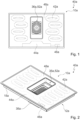
- Fig. 1 shows a hob 40a, which is designed as an induction hob, with a hob device 10a, which is designed as an induction hob device.
- the hob device 10a has a hob plate 48a. In an assembled state, the hob plate 48a forms part of a hob outer housing.
- the hob plate 48a is intended for placing cooking utensils (not shown).
- the hob device 10a has a plurality of heating units 42a.
- the heating units 42a are designed as induction heating units.
- the heating units 42a are arranged in the form of a matrix.
- the heating units could in particular be part of a classic hob, in which there could be fixed heating zones defined in particular by a position of the heating units, which could in particular be marked on the hob plate.
- the cooking surface device 10a has eight heating units 42a.
- Four of the heating units 42a define a variable cooking surface area.
- the heating units 42a defining a variable cooking surface area are arranged in a single row.
- the heating units 42a are intended to heat cooking utensils placed on the cooking surface plate 48a above the heating units 42a.
- the hob device 10a has a user interface 44a for inputting and/or selecting operating parameters, for example a heating power and/or a heating power density and/or a heating zone.
- the user interface 44a is provided for outputting a value of an operating parameter to an operator.
- the hob device 10a has a control unit 46a.
- the control unit 46 is designed to carry out actions and/or change settings depending on operating parameters entered via the user interface 44a. In an operating state, the control unit 46a regulates a power supply to the heating units 42a.
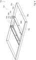
- the hob device 10a has a housing unit 12a (cf. Fig. 2 to 4 , 6 and 7 ). In an installation position, the housing unit 12a is arranged below the hob plate 48a. In the assembled state, the housing unit 12a is fastened to the hob plate 48a. In the assembled state, the housing unit 12a partially defines a receiving space 50a (cf. Fig. 4 , 6 and 7 ).
- the hob device 10a has two web-like reinforcement units 14a (cf. Fig. 4 to 7 ).
- the reinforcement units 14a are arranged parallel to one another in the assembled state.
- a first of the reinforcement units 14a has a longitudinal extension direction which is aligned parallel to a longitudinal extension direction of a second of the reinforcement units 14a.
- the housing unit 12a has a housing recess 36 (cf. Fig. 1, 2 and 4 ).
- the hob plate 48a has a plate recess 52a (cf. Fig. 1 and 2 ). In the installed position, the housing recess 36 is arranged substantially below the plate recess 52a.
- the housing recess 36a and the plate recess 52a are arranged corresponding to one another.
- the reinforcement units 14a are arranged on both sides of the housing recess 36a of the housing unit 12a. Only one of the reinforcement units 14a is described below.
- the reinforcement unit 14a which is provided for reinforcing the housing unit 12a, is fastened to the housing unit 12a (cf. Fig. 4 , 6 and 7 ).
- the reinforcement unit 14a is attached to the housing unit 12a at several locations.
- the reinforcement unit 14a has a fastening element 16a (cf. Fig. 5 ).
- the fastening element 16a has a main extension plane which is aligned substantially perpendicular to a longitudinal extension direction of the reinforcement unit 14a.
- the fastening element 16a is provided for fastening to a side wall 18a of the housing unit 12a.
- the fastening element 16a in the assembled state is fastened to the side wall 18a of the housing unit 12a by means of a rivet connection.
- the reinforcement unit 14a has a further fastening element 20a (cf. Fig. 4 to 7 ).
- the further fastening element 20a has a main extension plane which is aligned substantially perpendicular to a longitudinal extension direction of the reinforcement unit 14a. In the assembled state, the further fastening element 20a is provided for fastening to a further side wall 22a of the housing unit 12a.
- the further side wall 22a and the side wall 20a are opposite walls of the housing unit 12a.
- the reinforcement unit 14a connects the further side wall 22a and the side wall 20a to one another.
- the reinforcement unit 14a divides the receiving space 50a into subspaces.
- the further fastening element 20a is fastened in the assembled state to the further side wall 22a of the housing unit 12a by means of a rivet connection.
- the reinforcement unit 14a has two support elements 24a (cf. Fig. 4 to 7 ). Only one of the support elements 24a is described below.
- the support element 24a In the assembled state, the support element 24a is provided for supporting the reinforcement unit 14a on a base 26a of the housing unit 12a. In the assembled state, the support element 24a is provided for fastening to the base 26a of the housing unit 12a.
- the support element 24a has a main extension plane which, in the assembled state, is aligned substantially parallel to a main extension plane of the housing unit 12a.
- the reinforcement unit 14a has two support elements 28a (cf. Fig. 4 to 6 ). Only one of the support elements 28a is described below. In the assembled state, the support element 28a provides a support surface for a room divider element 30a.
- the hob device 10a has the room divider element 30a (cf. Fig. 6 ).
- the room divider element 30a In the assembled state, the room divider element 30a is arranged on a side of the reinforcement unit 14a opposite the base 26a of the housing unit 12a.
- the room divider element 30a In the assembled state, the room divider element 30a is arranged between the hob plate 48a and the housing unit 12a.
- the room divider element 30a has a main extension plane which, in the assembled state, is aligned substantially parallel to the main extension plane of the housing unit 12a.
- the support element 28a In the assembled state, the support element 28a is intended for attachment to the room divider element 30a.
- the support element 28a has a main extension plane which, in the assembled state, is aligned substantially parallel to the main extension plane of the housing unit 12a.
- the hob device 10a has two inner housing units 34a (cf. Fig. 7 ). Only one of the inner housing units 34a is shown. Only one of the inner housing units 34a is described below.
- the inner housing unit 34a In the installation position and in the assembled state, the inner housing unit 34a is arranged above the base 26a of the housing unit 12a. In the installation position and in the assembled state, the inner housing unit 34a is placed on the base 26a of the housing unit 12a.
- the reinforcement unit 14a has three position securing elements 32a (cf. Fig. 4 to 6 ). Only one of the position securing elements 32a is described below. In the assembled state, the position securing element 32a secures a position of the inner housing unit 34a relative to the housing unit 12a.
- the position securing element 32a presses a portion of the inner housing unit 34a onto the base 26a of the housing unit 12a. In the assembled state, the position securing element 32a clamps the portion of the inner housing unit 34a between the position securing element 32a and the base 26a of the housing unit 12a (cf. Fig. 7 ).
- the position securing element 32a is designed as a feature of the reinforcement unit 14a.
- the position securing element 32a is designed as a punched portion of the reinforcement unit 14a.
- the reinforcement unit 14a is designed in one piece.
- the reinforcement unit 14a is provided for reinforcing the housing unit 12a in a region of the housing recess 36a of the housing unit 12a. In the assembled state, the reinforcement unit 14a borders on the housing recess 36a of the housing unit 12a.
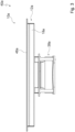
- the hob device 10a has an extractor unit 38a (cf. Fig. 2 and 3 ).
- the trigger unit 38a In the assembled state, the trigger unit 38a is fastened to the housing unit 12a. In the installed position, the trigger unit 38a is arranged below the housing unit 12a. In the installed position, the trigger unit 38a is arranged below the housing recess 36a.
- the housing recess 36a is designed as an air supply opening for the extractor unit 38a.
- the plate recess 52a is designed as an air supply opening for the extractor unit 38a.
- the extractor unit 38a sucks vapors from a cooking area through the plate recess 52a and through the housing recess 36a, which is located above the hob plate in particular in the installation position. 48a is located.
- the reinforcement unit 14a is attached to the side wall 18a of the housing unit 12a.
- the reinforcement unit 14a is attached to the further side wall 22a of the housing unit 12a.
- the reinforcement unit 14a is attached to the base 26a of the housing unit 12a.
- the room divider element 30a is placed on the support surface provided by the reinforcement unit 14a, in particular by the support element 28a of the reinforcement unit 14a, and attached to the reinforcement unit 14a.
- the housing unit 12a is attached to the hob plate 48a.
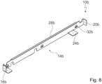
- FIG. 8 A further embodiment of the invention is shown.
- the following descriptions are essentially limited to the differences between the embodiments, whereby with regard to the same components, features and functions, reference is made to the description of the embodiment of the Fig. 1 to 7
- the letter a in the reference numerals of the embodiment in the Fig. 1 to 7 by the letter b in the reference numerals of the embodiment of the Fig. 8 With regard to identically designated components, in particular with regard to components with the same reference numerals, reference can also be made to the drawings and/or the description of the embodiment of the Fig. 1 to 7 be referred to.
- Fig. 8 shows a reinforcement unit 14b of an alternative hob device 10b.
- the reinforcement unit 14b has a single support element 28b.
- the support element 28b provides a support surface for a room divider element 30b.
- the support element 28b extends over a significant portion of a longitudinal extension of the reinforcement unit 14b.
Landscapes
- Engineering & Computer Science (AREA)
- Chemical & Material Sciences (AREA)
- Combustion & Propulsion (AREA)
- Mechanical Engineering (AREA)
- General Engineering & Computer Science (AREA)
- Physics & Mathematics (AREA)
- Electromagnetism (AREA)
- Baking, Grill, Roasting (AREA)
Claims (10)
- Dispositif de champ de cuisson avec une unité de carcasse (12a-b) et avec au moins une unité de renforcement en forme d'âme (14a-b), prévue pour un renforcement de l'unité de carcasse (12a-b) et fixée au moins dans un état monté à l'unité de carcasse (12a-b), caractérisé en ce que l'unité de renforcement (14a-b) présente au moins un élément de fixation (16a-b) prévu, à l'état monté, pour une fixation inamovible sans outil au moins à une paroi latérale (18a-b) de l'unité de carcasse (12a-b), dans lequel l'unité de renforcement (14a-b) présente au moins un élément de fixation supplémentaire (20a-b) prévu, à l'état monté, pour une fixation au moins à une paroi latérale supplémentaire (22a-b) de l'unité de carcasse (12a-b).
- Dispositif de champ de cuisson selon la revendication 1, caractérisé en ce que l'élément de fixation (16a-b) est, à l'état monté, fixé à la paroi latérale (18a-b) de l'unité de carcasse (12a-b) au moyen d'au moins une liaison rivetée.
- Dispositif de champ de cuisson selon l'une des revendications précédentes, caractérisé en ce que l'unité de renforcement (14a-b) présente au moins un élément de support (24a-b) prévu, à l'état monté, pour une fixation au moins à un fond (26a-b) de l'unité de carcasse (12a-b).
- Dispositif de champ de cuisson selon l'une des revendications précédentes, caractérisé en ce que l'unité de renforcement (14a-b) présente au moins un élément d'appui (28a-b) prévu, à l'état monté, pour fournir au moins une surface d'appui pour au moins un élément séparateur d'espace (30a-b).
- Dispositif de champ de cuisson selon l'une des revendications précédentes, caractérisé en ce que l'unité de renforcement (14a-b) présente au moins un élément de sécurisation de position (32a-b) prévu, à l'état monté, afin de sécuriser une position d'une unité de carcasse intérieure (34a-b) par rapport à l'unité de carcasse (12a-b).
- Dispositif de champ de cuisson selon l'une des revendications précédentes, caractérisé en ce que l'unité de renforcement (14a-b) est formée en une seule pièce.
- Dispositif de champ de cuisson selon l'une des revendications précédentes, caractérisé en ce que l'unité de renforcement (14a-b) est prévue, à l'état monté, pour un renforcement de l'unité de carcasse (12a-b) dans une zone d'un évidement de carcasse (36a-b) de l'unité de carcasse (12a-b).
- Dispositif de champ de cuisson selon l'une des revendications précédentes, caractérisé par une unité de tirage (38a-b) disposée, dans un état monté, sous l'unité de carcasse (12a-b).
- Dispositif de champ de cuisson selon la revendication 7 et 8, caractérisé en ce que l'évidement de carcasse (36a-b) est formé sous la forme d'un orifice d'admission d'air pour l'unité de tirage (38a-b).
- Champ de cuisson avec au moins un dispositif de champ de cuisson (10a-b) selon l'une des revendications précédentes.
Applications Claiming Priority (1)
| Application Number | Priority Date | Filing Date | Title |
|---|---|---|---|
| ES201630329A ES2633599B1 (es) | 2016-03-21 | 2016-03-21 | Dispositivo de campo de cocción |
Publications (3)
| Publication Number | Publication Date |
|---|---|
| EP3223585A1 EP3223585A1 (fr) | 2017-09-27 |
| EP3223585B1 EP3223585B1 (fr) | 2020-09-02 |
| EP3223585B2 true EP3223585B2 (fr) | 2024-10-16 |
Family
ID=58158957
Family Applications (1)
| Application Number | Title | Priority Date | Filing Date |
|---|---|---|---|
| EP17157771.1A Active EP3223585B2 (fr) | 2016-03-21 | 2017-02-24 | Plaque de cuisson |
Country Status (2)
| Country | Link |
|---|---|
| EP (1) | EP3223585B2 (fr) |
| ES (1) | ES2633599B1 (fr) |
Families Citing this family (5)
| Publication number | Priority date | Publication date | Assignee | Title |
|---|---|---|---|---|
| DE102018212151A1 (de) * | 2018-07-20 | 2020-01-23 | Wilhelm Bruckbauer | Kochfeldsystem |
| DE102019100046B4 (de) * | 2019-01-03 | 2020-12-24 | Miele & Cie. Kg | Kochfeldsystem |
| EP3677843A1 (fr) * | 2019-01-03 | 2020-07-08 | Miele & Cie. KG | Système de plaque de cuisson |
| US11536463B2 (en) | 2019-08-30 | 2022-12-27 | Whirlpool Corporation | Cooktop with side frame members |
| WO2023140798A1 (fr) * | 2021-09-08 | 2023-07-27 | Mamur Teknoloji Sistemleri San. A.S. | Plaque de cuisson avec élément de renforcement d'une plaque de base |
Family Cites Families (7)
| Publication number | Priority date | Publication date | Assignee | Title |
|---|---|---|---|---|
| US4562827A (en) * | 1984-11-21 | 1986-01-07 | Roper Corporation | Downdraft countertop cooking range |
| EP0675672A1 (fr) * | 1994-03-31 | 1995-10-04 | Superluck Electrics Corp. | Dispositif de radiation de chaleur pour élément chauffant par induction |
| DE19506803B4 (de) * | 1995-02-27 | 2008-05-08 | Toyotomi Co., Ltd., Nagoya | Koch- und Heizofen |
| US8269148B2 (en) * | 2008-09-25 | 2012-09-18 | Electrolux Home Products, Inc. | Cooktop with forced convection cooling |
| DE202009000990U1 (de) * | 2009-01-27 | 2009-03-26 | BSH Bosch und Siemens Hausgeräte GmbH | Induktionsspulenträgervorrichtung |
| ES2432418B1 (es) * | 2012-05-30 | 2014-10-15 | Bsh Electrodomésticos España, S.A. | Dispositivo de sujección de campo de cocción con una unidad de sujección, campo de cocción y procedimiento de fabricación |
| DE202013005303U1 (de) * | 2013-06-12 | 2013-06-24 | Wilhelm Bruckbauer | Kochfeld |
-
2016
- 2016-03-21 ES ES201630329A patent/ES2633599B1/es active Active
-
2017
- 2017-02-24 EP EP17157771.1A patent/EP3223585B2/fr active Active
Also Published As
| Publication number | Publication date |
|---|---|
| ES2633599B1 (es) | 2018-07-04 |
| EP3223585A1 (fr) | 2017-09-27 |
| EP3223585B1 (fr) | 2020-09-02 |
| ES2633599A1 (es) | 2017-09-22 |
Similar Documents
| Publication | Publication Date | Title |
|---|---|---|
| EP3223585B2 (fr) | Plaque de cuisson | |
| EP3338028B1 (fr) | Appareil combiné avec plaque de cuisson et dispositif d'evacuation des fumées | |
| WO2015049602A1 (fr) | Système de table de cuisson | |
| EP2475220B1 (fr) | Dispositif de champ de cuisson | |
| EP2595450A2 (fr) | Dispositif de cuisson | |
| EP3453974B1 (fr) | Dispositif formant plaque de cuisson | |
| EP2602556A2 (fr) | Dispositif de plan de cuisson | |
| EP3628932B1 (fr) | Plaque de cuisson | |
| DE102012219264A1 (de) | Hausgerätevorrichtung | |
| EP3267116B1 (fr) | Plaque de cuisson | |
| WO2008138760A1 (fr) | Dispositif de protection d'une unité de cuisson | |
| WO2008138751A1 (fr) | Table de cuisson | |
| EP3184911B1 (fr) | Système comprenant une table de cuisson et dispositif de réglage en hauteur | |
| DE102016202768A1 (de) | Kochfeldvorrichtung | |
| EP3679304B2 (fr) | Dispositif de plaque de cuisson | |
| EP3106758B1 (fr) | Plaque de cuisson | |
| EP3664579B1 (fr) | Dispositif formant appareil de cuisson à induction | |
| DE102013207787A1 (de) | Kochfeldvorrichtung | |
| EP3671046A1 (fr) | Système de cuisson | |
| EP3679303B1 (fr) | Dispositif de plaque de cuisson | |
| EP3386272A1 (fr) | Dispositif formant plaque de cuisson | |
| EP1840472B1 (fr) | Plaque de cuisson au gaz | |
| EP0407375A2 (fr) | Pièce de distance pour un outil pratiquement cylindrique et la méthode de sa fabrication | |
| EP1312868A1 (fr) | Agencement d'une plaque de cuisson et d'un fond intermédiaire et fond intermédiaire | |
| EP2884820B1 (fr) | Dispositif de plaque de cuisson |
Legal Events
| Date | Code | Title | Description |
|---|---|---|---|
| PUAI | Public reference made under article 153(3) epc to a published international application that has entered the european phase |
Free format text: ORIGINAL CODE: 0009012 |
|
| STAA | Information on the status of an ep patent application or granted ep patent |
Free format text: STATUS: THE APPLICATION HAS BEEN PUBLISHED |
|
| AK | Designated contracting states |
Kind code of ref document: A1 Designated state(s): AL AT BE BG CH CY CZ DE DK EE ES FI FR GB GR HR HU IE IS IT LI LT LU LV MC MK MT NL NO PL PT RO RS SE SI SK SM TR |
|
| AX | Request for extension of the european patent |
Extension state: BA ME |
|
| STAA | Information on the status of an ep patent application or granted ep patent |
Free format text: STATUS: REQUEST FOR EXAMINATION WAS MADE |
|
| 17P | Request for examination filed |
Effective date: 20180327 |
|
| RBV | Designated contracting states (corrected) |
Designated state(s): AL AT BE BG CH CY CZ DE DK EE ES FI FR GB GR HR HU IE IS IT LI LT LU LV MC MK MT NL NO PL PT RO RS SE SI SK SM TR |
|
| GRAP | Despatch of communication of intention to grant a patent |
Free format text: ORIGINAL CODE: EPIDOSNIGR1 |
|
| STAA | Information on the status of an ep patent application or granted ep patent |
Free format text: STATUS: GRANT OF PATENT IS INTENDED |
|
| INTG | Intention to grant announced |
Effective date: 20200326 |
|
| GRAS | Grant fee paid |
Free format text: ORIGINAL CODE: EPIDOSNIGR3 |
|
| GRAA | (expected) grant |
Free format text: ORIGINAL CODE: 0009210 |
|
| STAA | Information on the status of an ep patent application or granted ep patent |
Free format text: STATUS: THE PATENT HAS BEEN GRANTED |
|
| AK | Designated contracting states |
Kind code of ref document: B1 Designated state(s): AL AT BE BG CH CY CZ DE DK EE ES FI FR GB GR HR HU IE IS IT LI LT LU LV MC MK MT NL NO PL PT RO RS SE SI SK SM TR |
|
| REG | Reference to a national code |
Ref country code: GB Ref legal event code: FG4D Free format text: NOT ENGLISH |
|
| REG | Reference to a national code |
Ref country code: AT Ref legal event code: REF Ref document number: 1310361 Country of ref document: AT Kind code of ref document: T Effective date: 20200915 Ref country code: CH Ref legal event code: EP |
|
| REG | Reference to a national code |
Ref country code: DE Ref legal event code: R096 Ref document number: 502017006988 Country of ref document: DE |
|
| REG | Reference to a national code |
Ref country code: IE Ref legal event code: FG4D Free format text: LANGUAGE OF EP DOCUMENT: GERMAN |
|
| REG | Reference to a national code |
Ref country code: LT Ref legal event code: MG4D |
|
| PG25 | Lapsed in a contracting state [announced via postgrant information from national office to epo] |
Ref country code: NO Free format text: LAPSE BECAUSE OF FAILURE TO SUBMIT A TRANSLATION OF THE DESCRIPTION OR TO PAY THE FEE WITHIN THE PRESCRIBED TIME-LIMIT Effective date: 20201202 Ref country code: BG Free format text: LAPSE BECAUSE OF FAILURE TO SUBMIT A TRANSLATION OF THE DESCRIPTION OR TO PAY THE FEE WITHIN THE PRESCRIBED TIME-LIMIT Effective date: 20201202 Ref country code: GR Free format text: LAPSE BECAUSE OF FAILURE TO SUBMIT A TRANSLATION OF THE DESCRIPTION OR TO PAY THE FEE WITHIN THE PRESCRIBED TIME-LIMIT Effective date: 20201203 Ref country code: HR Free format text: LAPSE BECAUSE OF FAILURE TO SUBMIT A TRANSLATION OF THE DESCRIPTION OR TO PAY THE FEE WITHIN THE PRESCRIBED TIME-LIMIT Effective date: 20200902 Ref country code: SE Free format text: LAPSE BECAUSE OF FAILURE TO SUBMIT A TRANSLATION OF THE DESCRIPTION OR TO PAY THE FEE WITHIN THE PRESCRIBED TIME-LIMIT Effective date: 20200902 Ref country code: LT Free format text: LAPSE BECAUSE OF FAILURE TO SUBMIT A TRANSLATION OF THE DESCRIPTION OR TO PAY THE FEE WITHIN THE PRESCRIBED TIME-LIMIT Effective date: 20200902 Ref country code: FI Free format text: LAPSE BECAUSE OF FAILURE TO SUBMIT A TRANSLATION OF THE DESCRIPTION OR TO PAY THE FEE WITHIN THE PRESCRIBED TIME-LIMIT Effective date: 20200902 |
|
| REG | Reference to a national code |
Ref country code: NL Ref legal event code: MP Effective date: 20200902 |
|
| PG25 | Lapsed in a contracting state [announced via postgrant information from national office to epo] |
Ref country code: LV Free format text: LAPSE BECAUSE OF FAILURE TO SUBMIT A TRANSLATION OF THE DESCRIPTION OR TO PAY THE FEE WITHIN THE PRESCRIBED TIME-LIMIT Effective date: 20200902 Ref country code: PL Free format text: LAPSE BECAUSE OF FAILURE TO SUBMIT A TRANSLATION OF THE DESCRIPTION OR TO PAY THE FEE WITHIN THE PRESCRIBED TIME-LIMIT Effective date: 20200902 Ref country code: RS Free format text: LAPSE BECAUSE OF FAILURE TO SUBMIT A TRANSLATION OF THE DESCRIPTION OR TO PAY THE FEE WITHIN THE PRESCRIBED TIME-LIMIT Effective date: 20200902 |
|
| PG25 | Lapsed in a contracting state [announced via postgrant information from national office to epo] |
Ref country code: SM Free format text: LAPSE BECAUSE OF FAILURE TO SUBMIT A TRANSLATION OF THE DESCRIPTION OR TO PAY THE FEE WITHIN THE PRESCRIBED TIME-LIMIT Effective date: 20200902 Ref country code: EE Free format text: LAPSE BECAUSE OF FAILURE TO SUBMIT A TRANSLATION OF THE DESCRIPTION OR TO PAY THE FEE WITHIN THE PRESCRIBED TIME-LIMIT Effective date: 20200902 Ref country code: CZ Free format text: LAPSE BECAUSE OF FAILURE TO SUBMIT A TRANSLATION OF THE DESCRIPTION OR TO PAY THE FEE WITHIN THE PRESCRIBED TIME-LIMIT Effective date: 20200902 Ref country code: RO Free format text: LAPSE BECAUSE OF FAILURE TO SUBMIT A TRANSLATION OF THE DESCRIPTION OR TO PAY THE FEE WITHIN THE PRESCRIBED TIME-LIMIT Effective date: 20200902 Ref country code: PT Free format text: LAPSE BECAUSE OF FAILURE TO SUBMIT A TRANSLATION OF THE DESCRIPTION OR TO PAY THE FEE WITHIN THE PRESCRIBED TIME-LIMIT Effective date: 20210104 |
|
| PG25 | Lapsed in a contracting state [announced via postgrant information from national office to epo] |
Ref country code: AL Free format text: LAPSE BECAUSE OF FAILURE TO SUBMIT A TRANSLATION OF THE DESCRIPTION OR TO PAY THE FEE WITHIN THE PRESCRIBED TIME-LIMIT Effective date: 20200902 Ref country code: ES Free format text: LAPSE BECAUSE OF FAILURE TO SUBMIT A TRANSLATION OF THE DESCRIPTION OR TO PAY THE FEE WITHIN THE PRESCRIBED TIME-LIMIT Effective date: 20200902 Ref country code: IS Free format text: LAPSE BECAUSE OF FAILURE TO SUBMIT A TRANSLATION OF THE DESCRIPTION OR TO PAY THE FEE WITHIN THE PRESCRIBED TIME-LIMIT Effective date: 20210102 |
|
| REG | Reference to a national code |
Ref country code: DE Ref legal event code: R026 Ref document number: 502017006988 Country of ref document: DE |
|
| PLBI | Opposition filed |
Free format text: ORIGINAL CODE: 0009260 |
|
| PLAX | Notice of opposition and request to file observation + time limit sent |
Free format text: ORIGINAL CODE: EPIDOSNOBS2 |
|
| PG25 | Lapsed in a contracting state [announced via postgrant information from national office to epo] |
Ref country code: SK Free format text: LAPSE BECAUSE OF FAILURE TO SUBMIT A TRANSLATION OF THE DESCRIPTION OR TO PAY THE FEE WITHIN THE PRESCRIBED TIME-LIMIT Effective date: 20200902 |
|
| 26 | Opposition filed |
Opponent name: ELECTROLUX ROTHENBURG GMBH FACTORY AND DEVELOPMENT Effective date: 20210601 |
|
| PG25 | Lapsed in a contracting state [announced via postgrant information from national office to epo] |
Ref country code: SI Free format text: LAPSE BECAUSE OF FAILURE TO SUBMIT A TRANSLATION OF THE DESCRIPTION OR TO PAY THE FEE WITHIN THE PRESCRIBED TIME-LIMIT Effective date: 20200902 Ref country code: DK Free format text: LAPSE BECAUSE OF FAILURE TO SUBMIT A TRANSLATION OF THE DESCRIPTION OR TO PAY THE FEE WITHIN THE PRESCRIBED TIME-LIMIT Effective date: 20200902 |
|
| PG25 | Lapsed in a contracting state [announced via postgrant information from national office to epo] |
Ref country code: MC Free format text: LAPSE BECAUSE OF FAILURE TO SUBMIT A TRANSLATION OF THE DESCRIPTION OR TO PAY THE FEE WITHIN THE PRESCRIBED TIME-LIMIT Effective date: 20200902 |
|
| PLBB | Reply of patent proprietor to notice(s) of opposition received |
Free format text: ORIGINAL CODE: EPIDOSNOBS3 |
|
| GBPC | Gb: european patent ceased through non-payment of renewal fee |
Effective date: 20210224 |
|
| REG | Reference to a national code |
Ref country code: BE Ref legal event code: MM Effective date: 20210228 |
|
| PG25 | Lapsed in a contracting state [announced via postgrant information from national office to epo] |
Ref country code: LU Free format text: LAPSE BECAUSE OF NON-PAYMENT OF DUE FEES Effective date: 20210224 |
|
| PG25 | Lapsed in a contracting state [announced via postgrant information from national office to epo] |
Ref country code: GB Free format text: LAPSE BECAUSE OF NON-PAYMENT OF DUE FEES Effective date: 20210224 Ref country code: FR Free format text: LAPSE BECAUSE OF NON-PAYMENT OF DUE FEES Effective date: 20210228 Ref country code: IE Free format text: LAPSE BECAUSE OF NON-PAYMENT OF DUE FEES Effective date: 20210224 |
|
| PG25 | Lapsed in a contracting state [announced via postgrant information from national office to epo] |
Ref country code: BE Free format text: LAPSE BECAUSE OF NON-PAYMENT OF DUE FEES Effective date: 20210228 |
|
| PG25 | Lapsed in a contracting state [announced via postgrant information from national office to epo] |
Ref country code: HU Free format text: LAPSE BECAUSE OF FAILURE TO SUBMIT A TRANSLATION OF THE DESCRIPTION OR TO PAY THE FEE WITHIN THE PRESCRIBED TIME-LIMIT; INVALID AB INITIO Effective date: 20170224 |
|
| PG25 | Lapsed in a contracting state [announced via postgrant information from national office to epo] |
Ref country code: NL Free format text: LAPSE BECAUSE OF NON-PAYMENT OF DUE FEES Effective date: 20200923 Ref country code: CY Free format text: LAPSE BECAUSE OF FAILURE TO SUBMIT A TRANSLATION OF THE DESCRIPTION OR TO PAY THE FEE WITHIN THE PRESCRIBED TIME-LIMIT Effective date: 20200902 |
|
| PLAB | Opposition data, opponent's data or that of the opponent's representative modified |
Free format text: ORIGINAL CODE: 0009299OPPO |
|
| R26 | Opposition filed (corrected) |
Opponent name: ELECTROLUX ROTHENBURG GMBH FACTORY AND DEVELOPMENT Effective date: 20210601 |
|
| PG25 | Lapsed in a contracting state [announced via postgrant information from national office to epo] |
Ref country code: MK Free format text: LAPSE BECAUSE OF FAILURE TO SUBMIT A TRANSLATION OF THE DESCRIPTION OR TO PAY THE FEE WITHIN THE PRESCRIBED TIME-LIMIT Effective date: 20200902 |
|
| PG25 | Lapsed in a contracting state [announced via postgrant information from national office to epo] |
Ref country code: TR Free format text: LAPSE BECAUSE OF FAILURE TO SUBMIT A TRANSLATION OF THE DESCRIPTION OR TO PAY THE FEE WITHIN THE PRESCRIBED TIME-LIMIT Effective date: 20200902 |
|
| PUAH | Patent maintained in amended form |
Free format text: ORIGINAL CODE: 0009272 |
|
| STAA | Information on the status of an ep patent application or granted ep patent |
Free format text: STATUS: PATENT MAINTAINED AS AMENDED |
|
| PG25 | Lapsed in a contracting state [announced via postgrant information from national office to epo] |
Ref country code: MT Free format text: LAPSE BECAUSE OF FAILURE TO SUBMIT A TRANSLATION OF THE DESCRIPTION OR TO PAY THE FEE WITHIN THE PRESCRIBED TIME-LIMIT Effective date: 20200902 |
|
| 27A | Patent maintained in amended form |
Effective date: 20241016 |
|
| AK | Designated contracting states |
Kind code of ref document: B2 Designated state(s): AL AT BE BG CH CY CZ DE DK EE ES FI FR GB GR HR HU IE IS IT LI LT LU LV MC MK MT NL NO PL PT RO RS SE SI SK SM TR |
|
| REG | Reference to a national code |
Ref country code: DE Ref legal event code: R102 Ref document number: 502017006988 Country of ref document: DE |
|
| PGFP | Annual fee paid to national office [announced via postgrant information from national office to epo] |
Ref country code: DE Payment date: 20250228 Year of fee payment: 9 |
|
| PGFP | Annual fee paid to national office [announced via postgrant information from national office to epo] |
Ref country code: AT Payment date: 20250217 Year of fee payment: 9 Ref country code: CH Payment date: 20250301 Year of fee payment: 9 |
|
| PGFP | Annual fee paid to national office [announced via postgrant information from national office to epo] |
Ref country code: IT Payment date: 20250228 Year of fee payment: 9 |
|
| REG | Reference to a national code |
Ref country code: CH Ref legal event code: U11 Free format text: ST27 STATUS EVENT CODE: U-0-0-U10-U11 (AS PROVIDED BY THE NATIONAL OFFICE) Effective date: 20260301 |