EP3222869B1 - Drehmomentbegrenzungsvorrichtung - Google Patents
Drehmomentbegrenzungsvorrichtung Download PDFInfo
- Publication number
- EP3222869B1 EP3222869B1 EP16162452.3A EP16162452A EP3222869B1 EP 3222869 B1 EP3222869 B1 EP 3222869B1 EP 16162452 A EP16162452 A EP 16162452A EP 3222869 B1 EP3222869 B1 EP 3222869B1
- Authority
- EP
- European Patent Office
- Prior art keywords
- limiting device
- torque limiting
- input
- torsion spring
- output shaft
- Prior art date
- Legal status (The legal status is an assumption and is not a legal conclusion. Google has not performed a legal analysis and makes no representation as to the accuracy of the status listed.)
- Active
Links
- 230000008878 coupling Effects 0.000 claims description 27
- 238000010168 coupling process Methods 0.000 claims description 27
- 238000005859 coupling reaction Methods 0.000 claims description 27
- 230000036316 preload Effects 0.000 claims description 12
- 230000003068 static effect Effects 0.000 claims description 10
- 229910001069 Ti alloy Inorganic materials 0.000 claims description 3
- RTAQQCXQSZGOHL-UHFFFAOYSA-N Titanium Chemical compound [Ti] RTAQQCXQSZGOHL-UHFFFAOYSA-N 0.000 claims description 3
- 229910052719 titanium Inorganic materials 0.000 claims description 3
- 239000010936 titanium Substances 0.000 claims description 3
- 230000005540 biological transmission Effects 0.000 description 8
- 230000000694 effects Effects 0.000 description 3
- 238000010276 construction Methods 0.000 description 2
- 239000000463 material Substances 0.000 description 2
- 238000006073 displacement reaction Methods 0.000 description 1
- 230000002427 irreversible effect Effects 0.000 description 1
- 230000004048 modification Effects 0.000 description 1
- 238000012986 modification Methods 0.000 description 1
Images


Classifications
-
- B—PERFORMING OPERATIONS; TRANSPORTING
- B64—AIRCRAFT; AVIATION; COSMONAUTICS
- B64C—AEROPLANES; HELICOPTERS
- B64C13/00—Control systems or transmitting systems for actuating flying-control surfaces, lift-increasing flaps, air brakes, or spoilers
- B64C13/24—Transmitting means
- B64C13/38—Transmitting means with power amplification
- B64C13/50—Transmitting means with power amplification using electrical energy
-
- B—PERFORMING OPERATIONS; TRANSPORTING
- B64—AIRCRAFT; AVIATION; COSMONAUTICS
- B64C—AEROPLANES; HELICOPTERS
- B64C9/00—Adjustable control surfaces or members, e.g. rudders
- B64C9/14—Adjustable control surfaces or members, e.g. rudders forming slots
- B64C9/22—Adjustable control surfaces or members, e.g. rudders forming slots at the front of the wing
- B64C9/24—Adjustable control surfaces or members, e.g. rudders forming slots at the front of the wing by single flap
-
- F—MECHANICAL ENGINEERING; LIGHTING; HEATING; WEAPONS; BLASTING
- F16—ENGINEERING ELEMENTS AND UNITS; GENERAL MEASURES FOR PRODUCING AND MAINTAINING EFFECTIVE FUNCTIONING OF MACHINES OR INSTALLATIONS; THERMAL INSULATION IN GENERAL
- F16D—COUPLINGS FOR TRANSMITTING ROTATION; CLUTCHES; BRAKES
- F16D3/00—Yielding couplings, i.e. with means permitting movement between the connected parts during the drive
- F16D3/50—Yielding couplings, i.e. with means permitting movement between the connected parts during the drive with the coupling parts connected by one or more intermediate members
- F16D3/72—Yielding couplings, i.e. with means permitting movement between the connected parts during the drive with the coupling parts connected by one or more intermediate members with axially-spaced attachments to the coupling parts
-
- F—MECHANICAL ENGINEERING; LIGHTING; HEATING; WEAPONS; BLASTING
- F16—ENGINEERING ELEMENTS AND UNITS; GENERAL MEASURES FOR PRODUCING AND MAINTAINING EFFECTIVE FUNCTIONING OF MACHINES OR INSTALLATIONS; THERMAL INSULATION IN GENERAL
- F16D—COUPLINGS FOR TRANSMITTING ROTATION; CLUTCHES; BRAKES
- F16D41/00—Freewheels or freewheel clutches
- F16D41/02—Freewheels or freewheel clutches disengaged by contact of a part of or on the freewheel or freewheel clutch with a stationarily-mounted member
-
- F—MECHANICAL ENGINEERING; LIGHTING; HEATING; WEAPONS; BLASTING
- F16—ENGINEERING ELEMENTS AND UNITS; GENERAL MEASURES FOR PRODUCING AND MAINTAINING EFFECTIVE FUNCTIONING OF MACHINES OR INSTALLATIONS; THERMAL INSULATION IN GENERAL
- F16D—COUPLINGS FOR TRANSMITTING ROTATION; CLUTCHES; BRAKES
- F16D41/00—Freewheels or freewheel clutches
- F16D41/06—Freewheels or freewheel clutches with intermediate wedging coupling members between an inner and an outer surface
- F16D41/064—Freewheels or freewheel clutches with intermediate wedging coupling members between an inner and an outer surface the intermediate members wedging by rolling and having a circular cross-section, e.g. balls
- F16D41/066—Freewheels or freewheel clutches with intermediate wedging coupling members between an inner and an outer surface the intermediate members wedging by rolling and having a circular cross-section, e.g. balls all members having the same size and only one of the two surfaces being cylindrical
- F16D41/067—Freewheels or freewheel clutches with intermediate wedging coupling members between an inner and an outer surface the intermediate members wedging by rolling and having a circular cross-section, e.g. balls all members having the same size and only one of the two surfaces being cylindrical and the members being distributed by a separate cage encircling the axis of rotation
-
- F—MECHANICAL ENGINEERING; LIGHTING; HEATING; WEAPONS; BLASTING
- F16—ENGINEERING ELEMENTS AND UNITS; GENERAL MEASURES FOR PRODUCING AND MAINTAINING EFFECTIVE FUNCTIONING OF MACHINES OR INSTALLATIONS; THERMAL INSULATION IN GENERAL
- F16D—COUPLINGS FOR TRANSMITTING ROTATION; CLUTCHES; BRAKES
- F16D43/00—Automatic clutches
- F16D43/02—Automatic clutches actuated entirely mechanically
-
- F—MECHANICAL ENGINEERING; LIGHTING; HEATING; WEAPONS; BLASTING
- F16—ENGINEERING ELEMENTS AND UNITS; GENERAL MEASURES FOR PRODUCING AND MAINTAINING EFFECTIVE FUNCTIONING OF MACHINES OR INSTALLATIONS; THERMAL INSULATION IN GENERAL
- F16D—COUPLINGS FOR TRANSMITTING ROTATION; CLUTCHES; BRAKES
- F16D47/00—Systems of clutches, or clutches and couplings, comprising devices of types grouped under at least two of the preceding guide headings
- F16D47/02—Systems of clutches, or clutches and couplings, comprising devices of types grouped under at least two of the preceding guide headings of which at least one is a coupling
-
- F—MECHANICAL ENGINEERING; LIGHTING; HEATING; WEAPONS; BLASTING
- F16—ENGINEERING ELEMENTS AND UNITS; GENERAL MEASURES FOR PRODUCING AND MAINTAINING EFFECTIVE FUNCTIONING OF MACHINES OR INSTALLATIONS; THERMAL INSULATION IN GENERAL
- F16D—COUPLINGS FOR TRANSMITTING ROTATION; CLUTCHES; BRAKES
- F16D47/00—Systems of clutches, or clutches and couplings, comprising devices of types grouped under at least two of the preceding guide headings
- F16D47/04—Systems of clutches, or clutches and couplings, comprising devices of types grouped under at least two of the preceding guide headings of which at least one is a freewheel
-
- F—MECHANICAL ENGINEERING; LIGHTING; HEATING; WEAPONS; BLASTING
- F16—ENGINEERING ELEMENTS AND UNITS; GENERAL MEASURES FOR PRODUCING AND MAINTAINING EFFECTIVE FUNCTIONING OF MACHINES OR INSTALLATIONS; THERMAL INSULATION IN GENERAL
- F16D—COUPLINGS FOR TRANSMITTING ROTATION; CLUTCHES; BRAKES
- F16D3/00—Yielding couplings, i.e. with means permitting movement between the connected parts during the drive
- F16D3/02—Yielding couplings, i.e. with means permitting movement between the connected parts during the drive adapted to specific functions
- F16D3/10—Couplings with means for varying the angular relationship of two coaxial shafts during motion
-
- Y—GENERAL TAGGING OF NEW TECHNOLOGICAL DEVELOPMENTS; GENERAL TAGGING OF CROSS-SECTIONAL TECHNOLOGIES SPANNING OVER SEVERAL SECTIONS OF THE IPC; TECHNICAL SUBJECTS COVERED BY FORMER USPC CROSS-REFERENCE ART COLLECTIONS [XRACs] AND DIGESTS
- Y02—TECHNOLOGIES OR APPLICATIONS FOR MITIGATION OR ADAPTATION AGAINST CLIMATE CHANGE
- Y02T—CLIMATE CHANGE MITIGATION TECHNOLOGIES RELATED TO TRANSPORTATION
- Y02T50/00—Aeronautics or air transport
- Y02T50/40—Weight reduction
Definitions
- the present disclosure relates to torque limiting devices as may be used, for example, in aircraft actuator systems.
- Torque limiting devices are used in a wide variety of applications.
- One such application is in actuators used in aircraft, where the actuators may be used to deploy control surfaces, for example flaps or slats.
- Power is transmitted to a plurality of linked actuators from a central power drive unit.
- Torque limiting devices are used with each actuator to limit the maximum torque delivered to the actuator's output in the case of the deployed surface jamming. Without a torque limiting device, the entire output torque of the power drive unit would feed directly into the jammed component, requiring the relevant structure to be sized to resist such loading. This will result in weight penalties on the aircraft, which is undesirable.
- torque limiting devices may use multiple interleaved friction plates or a torsion bar system. Whilst these systems are effective in certain applications, there remains an ongoing effort to create alternative forms of torque limiting devices.
- US 2016/0016653 A1 discloses a torque limiting device according to the preamble of claim 1.
- JP S61 124725U discloses a drive arrangement comprising an input shaft and an output shaft coupled by a flexible coupling.
- EP 2889504 A1 discloses an irreversible mechanism.
- the present invention provides a torque limiting device as set forth in claim 1
- the torsion spring may be a machined torsion spring.
- the torsion spring may be arranged around the input and output shafts.
- the jamming mechanism may comprise a plurality of ramp surfaces provided on the input shaft (56), a static structure (66) of the device and a plurality of roller elements arranged between the input shaft and the static structure.
- the roller elements may be received between adjacent ramp surfaces on the input shaft.
- the mechanism may further comprise an actuator coupled to the output shaft for moving the roller elements along the ramp surfaces upon relative rotation of the input and output shafts.
- the actuator may comprise a plurality of teeth extending between adjacent roller elements.
- the teeth may project from one end of the output shaft.
- Adjacent ramp surfaces may be circumferentially symmetrical.
- the output shaft may comprise a gear for connection to an actuator input.
- the torsion spring may comprise means for varying the preload of the spring.
- At least one end of the torsion spring may comprise a series of circumferentially spaced opposed openings for receiving a respective coupling pin therein.
- the torsion spring may be made from titanium or titanium alloy.
- the disclosure also extends to an actuator system comprising an actuator having an input coupled to the output shaft of a torque limiting device as described in nany of the foregoing paragraphs.
- the disclosure also extends to an aircraft system comprising a plurality of actuator systems as above coupled in series to a common power drive unit.
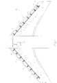
- Figure 1 illustrates an aircraft slat operating system 2.
- the system comprises a plurality of leading edge slats 4 which are selectively deployed and retracted by rotary actuators 6.
- Each actuator 6 is powered by a rotary drive from a common power drive unit 8.
- Drive is transmitted from the power drive unit 8 via a series of power transmission shaft 10 which connect the actuators 6 in series.
- Brakes 12 and asymmetry sensors 14 may also be included in a typical system.
- the actuators 6 deploy and retract the slats 4. Should one of the slats 4 jam, then potentially the entire output of the power drive unit 8 may be input into that slat 4. The slat 4 and the surrounding aircraft structure would then have to be sized to react those forces, which may result in additional weight, which is undesirable. It is therefore customary to associate torque limiters with the actuators 6.
- FIGS 2 to 6 illustrate a rotary actuator drive 20 incorporating a torque limiting device in accordance with this disclosure.
- the rotary actuator drive 20 comprises a drive portion 22 and an associated torque limiting device 24.
- the rotary actuator drive 20 includes a drive shaft 26 which extends along the entire length of the drive 20.
- the drive shaft 26 includes splines 28 at each end, for connection, for example, to splines provided at the ends of power transmission shafts 10 as discussed above.
- the drive 20 further comprises a housing 30 which houses the drive portion 22 and the torque limiting device 24.
- the housing 30 comprises first and second housing parts 32, 34 joined together at a flanged joint 36.
- the end of the second housing part 32 remote from the flanged joint 36 is closed by a cover 38 which supports a bearing 40 which supports one end portion 42 of the drive shaft 26 and a rotary seal 44.
- the housing 30 may have other constructions.
- the housing 30 is fixed to static structure in use.
- the first housing part 32 substantially accommodates the drive portion 22 and the second housing part 34 the torque limiting device 24.
- the drive portion 22 comprises a planetary gear system 46 which receives its input from an external gear 48 provided on an output shaft 50 of the torque limiting device 24.
- the output of the planetary gear system 46 is coupled to an external shaft 52 which is supported on the shaft 26 for rotation relative thereto by means of a bearing 54.
- the planetary gear system 46 acts to reduce the rotational speed of the drive shaft 26 for input to an actuator.
- the torque limiting device 24 is arranged at the end 42 of the shaft 26.
- the torque limiting device 24 comprises an input shaft 56, which in this embodiment is provided by the end portion 42 of the drive shaft 26. That end portion 42 of the shaft 26 also comprises a roller receiving surface 58 which receives a plurality of roller elements 60 and a seat 62 for rotatably receiving the output shaft 50 of the torque limiting device 24.
- the roller receiving surface 58 is provided with a plurality of symmetrical ramps 64 between which the roller elements 60 locate (see Figure 4A ).
- the roller elements 60 are received within a ring 66 which is attached to or forms a part of the second housing part 34 and forms a static structure.
- the output shaft 50 has an external gear 48 formed at one end thereof for providing an input to the planetary gear system 46. At its other end it comprises a plurality of projecting teeth 68 which, as can be seen from Figure 4 extend between the roller elements 60. As will be explained further below, the roller elements 60, ramps 64, teeth 68 and static ring 66 together form a jamming mechanism 78.
- the output shaft 50 in this embodiment has a waisted central region 70 and first and second ends 72, 74, formed in this embodiment as flanges. This arrangement saves weight, but other configurations can be envisaged.
- torsion spring 80 Arranged around the output shaft 50 is mounted a machined torsion spring 80.
- the torsion spring 80 is made from titanium or titanium alloy, although other materials may be used.
- the material of the spring 80 is chosen to provide the necessary strength and torsional compliance.
- the torsion spring 80 has first and second ends 82, 84. Both ends 82, 84 are formed with openings 86 for receiving the ends of first and second coupling pins 88, 90. As shown in Figure 5 , at least the first end 82 of the torsion spring 80 is provided with a series of circumferentially spaced, diametrically opposed openings 86 for a purpose to be described further below. The second end 84 may be provided with just one pair of opposed openings 86. The first and second ends 82, 84 of the torsion spring 80 may be covered by caps 92 which may radially retain the coupling pins 88, 90.
- the first coupling pin 88 extends through opposed respective openings 94 in the input shaft 56 and through opposed openings 96 in the first end 72 of the output shaft 50.
- the second coupling pins 90 extends through opposed openings 98 in input shaft 56 and opposed openings 100 in the second end 74 of the output shaft 50.
- the openings 94, 96 and the openings 98, 100 are aligned to allow passage of the respective coupling pins 88, 90.
- Each opening 94, 96, 98, 100 is circumferentially larger than the coupling pin 88, 90 it receives, having an angular extent ⁇ . This allows will allow relative rotational movement between the input shaft 51 and output shaft 50 as will be described further below.
- the angle ⁇ may be between 10 and 15° for example.
- the torsion spring 80 is torsionally preloaded. That is, the first and second ends 82, 84 of the torsion spring 80 are rotated in opposite directions from one another from the spring's rest position, before the coupling pins 88, 90 are inserted through the openings 94, 96, 98, 100.
- the required degree of preload is achieved by engaging the second coupling pin 90 in the openings 86 at the second end 84 of the torsion spring and the coupling pin 88 in the desired pair of opposed openings 86 in the first end 82 of the torsion spring 80.
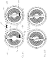
- the effect of this is to bias the coupling pins 88, 90 into contact with the walls of the openings 82, 84 in the input and output shafts 56, 50, as shown in Figures 4 and 5 .
- the first coupling pin 88 is biased into contact with clockwise (in the sense of Figure 5 ) facing surfaces 102, 104 of the openings 94, 96.
- the second coupling pin 90 is biased into contact with the counter-clockwise (in the sense of Figure 6 ) facing surfaces 106, 108 of the openings 98, 100.
- the drive shaft 26 of the drive 20 may rotate in either a clockwise or counter-clockwise direction, depending on the required direction of rotation of the actuator output shaft 22.
- Figure 7A illustrates how torque is transmitted between the input and output shafts 56, 50 of the torque limiting device when drive shaft 26 is rotating in a counter-clockwise direction in the sense of Figures 5 and 6 .
- the counter-clockwise facing surfaces 106 of the openings 98 in the input shaft 56 transmits torque transmit torque to the coupling pin 80.
- This torque is then transmitted into the second end 84 of the torsion spring 80, through the torsion spring 80 into the first end 82 of the torsion spring 80 and from there into the first coupling pin 88.
- the first coupling pin 88 then transmits the torque to the clockwise facing surfaces 104 of the openings 96 in the first end 72 of the output shaft 50, thereby causing the output shaft 50 to rotate, thereby providing torque to the drive portion through the ring gear 48.
- the output shaft 50 will rotate at the same speed as the input shaft 56, so that there is no relative rotation between the two shafts.
- Figure 8A illustrates how torque is transmitted between the input and output shafts 56, 50 of the torque limiting device when drive shaft 26 is rotating in a clockwise direction in the sense of Figures 5 and 6 .
- the clockwise facing surfaces 102 of the openings 94 in the first end 72 of the input shaft 56 transmits torque transmit torque to the first coupling pin 78.
- This torque is then transmitted into the first end 82 of the torsion spring 80, through the torsion spring 80 into the second end 82 of the torsion spring 80 and from there into the second coupling pin 88.
- the second coupling pin 90 then transmits the torque to the counter-clockwise facing surfaces 108 of the openings 100 in the second end 74 of the output shaft 50, thereby causing the output shaft 50 to rotate, thereby providing torque to the drive portion through the ring gear 48.
- the output shaft 50 will rotate at the same speed as the input shaft 56, so that there is no relative rotation between the two shafts.
- the preload of the torsion spring 80 is set at a level such that during normal operation, the torque transmitted through the torsion spring 80 does not exceed the preload. In effect, the preload sets a minimum torque limiter setting. In such circumstances, the input and output shafts 56, 50 will rotate together at the same speed, with the required torque being transmitted to the actuator drive. However, should, for example, the actuator jam (as might happen if a control surface to which it is coupled jams) then the output shaft 50 would cease to rotate, or at least rotate more slowly. This will result in the torsion spring 80 preload being exceeded.
- the device will operate at the same degree of relative angular displacement irrespective of the direction of rotation of the input shaft 51.
- the aim of the torque limiting device 24 is to operate as quickly as possible after a fault occurs to avoid damage to the actuator or component to which it is mounted.
- the torque value with which the torque limiting device 24 will operate is determined by the torsional spring rate of the torsion spring 80 and the degree of preload.
- the jamming mechanism 78 is activated with about 5° of relative rotational movement of the input and output shafts 56, 50.
- the ratio of the minimum setting torque, determined by the torsion spring preload, and the torque at which the jamming mechanism operates may be in the region of 1:1.08.
- the embodiment described herein has a number of advantages.
- the torsion spring 80 In view of the arrangement of the torsion spring 80 around the input and output shafts 56, 58, it provides a relatively compact construction, which is advantageous in restricted operating spaces, such as aircraft wings. Also, the desired degree of preload of the torsion spring 80 can be easily set.
- the output shaft 50 of the torque limiting device has been illustrated as a single component, it may be formed as a number of components suitably joined or coupled together.
- the pattern of openings 86 in the spring end 84 may differ in order to achieve the required resolution of preload in the spring.
- a combination of openings 86 may also be provided in both spring ends 82 and 84 to further enhance preload setting. Although these openings 86 are depicted as holes they may take the form of slots
- machined torsion spring 80 has been disclosed, other torsion springs may be used, for example coil springs.
- Machined torsion springs may, however, be advantageous in that they facilitate providing integrated spring ends for receiving the coupling pins.
- torque limiting device has been disclosed as being used in an aircraft actuator application, it may of course be used in other applications.
Landscapes
- Engineering & Computer Science (AREA)
- General Engineering & Computer Science (AREA)
- Mechanical Engineering (AREA)
- Aviation & Aerospace Engineering (AREA)
- Automation & Control Theory (AREA)
- Transmission Devices (AREA)
- One-Way And Automatic Clutches, And Combinations Of Different Clutches (AREA)
- Retarders (AREA)
Claims (15)
- Drehmomentbegrenzungsvorrichtung (24) umfassend:eine Eingangswelle (56);eine Ausgangswelle (50); undeinen Klemmmechanismus (78), der als Reaktion auf eine relative Drehung zwischen der Eingangswelle (56) und der Ausgangswelle (50) betrieben werden kann, um eine Drehung sowohl von der Eingangswelle (56) als auch der Ausgangswelle (50) zu stoppen, dadurch gekennzeichnet, dass die Drehmomentbegrenzungsvorrichtung (24) ferner Folgendes umfasst:
eine torsionsmäßig vorbelastete Torsionsfeder (80), die ein erstes Ende (82) und ein zweites Ende (84) aufweist, wobei das erste Ende (82) und das zweite Ende (84) der Torsionsfeder (80) sowohl an die Eingangswelle (56) als auch die Ausgangswelle (50) gekoppelt sind, wobei ein Drehmoment zwischen der Eingangswelle (56) und der Ausgangswelle (50) über die vorbelastete Torsionsfeder (80) übertragen wird, wobei die Kopplungen zwischen der Torsionsfeder (80) und der Eingangswelle (56) und der Ausgangswelle (50) eine begrenzte relative Drehung zwischen der Eingangswelle (56) und der Ausgangswelle (50) ermöglichen, wobei die Kopplungen zwischen dem ersten und zweiten Ende (82, 84) der Torsionsfeder (80) und der Eingangs- und Ausgangswelle (56, 50) einen ersten und zweiten Kupplungsstift (88, 90) umfassen, die sich durch entsprechende Öffnungen (94, 96, 98, 100) in der Eingangs- und Ausgangswelle (56, 50) in die Torsionsfeder (80) erstrecken, und wobei sich die Öffnungen (94, 96, 98, 100) in der Eingangs- und Ausgangswelle (56, 50) über einen umlaufenden Bogen (α) erstrecken, der größer als der Durchmesser der Kupplungsstifte (88, 90) ist, um eine relative Drehbewegung der Eingangs- und Ausgangswelle zu ermöglichen. - Drehmomentbegrenzungsvorrichtung nach Anspruch 1, wobei die Torsionsfeder (80) eine maschinell bearbeitete Torsionsfeder ist.
- Drehmomentbegrenzungsvorrichtung nach Anspruch 1 oder 2, wobei der umlaufende Bogen (α) im Bereich von 10-20° liegt.
- Drehmomentbegrenzungsvorrichtung nach Anspruch 3, wobei der umlaufende Bogen 15° beträgt.
- Drehmomentbegrenzungsvorrichtung nach einem der vorhergehenden Ansprüche, wobei die Torsionsfeder (80) um die Eingangs- und Ausgangswelle (56, 50) angeordnet ist, sodass sich eine Mittelachse der Feder (80) in dieselbe Richtung wie eine Mittelachse der Eingangs- und Ausgangswelle (56, 50) erstreckt.
- Drehmomentbegrenzungsvorrichtung nach einem der vorhergehenden Ansprüche, wobei der Klemmmechanismus (78) Folgendes umfasst:eine Vielzahl von Rampenflächen (64), die an der Eingangswelle (56) bereitgestellt sind;eine statische Struktur (66) der Vorrichtung, die drehbar statisch ist;eine Vielzahl von Rollenelementen (60), die zwischen der Eingangswelle (56) und der statischen Struktur (66) angeordnet sind und zwischen angrenzenden Rampenflächen (64) empfangen werden; undeine Betätigungseinrichtung, die zum Bewegen der Rollenelemente (60) entlang der Rampenflächen (64) bei einer relativen Drehung der Eingangs- und Ausgangswelle (56, 50) an die Außenwelle (50) gekoppelt ist.
- Drehmomentbegrenzungsvorrichtung nach Anspruch 6, wobei die Betätigungseinrichtung eine Vielzahl von Zähnen (68) umfasst, die sich zwischen den angrenzenden Rollenelementen (60) erstrecken.
- Drehmomentbegrenzungsvorrichtung nach Anspruch 7, wobei die Zähne (68) aus einen Ende der Ausgangswelle (50) hervorragen.
- Drehmomentbegrenzungsvorrichtung nach Anspruch 6, 7 oder 8, wobei angrenzende Rampenflächen (64) umfänglich symmetrisch sind.
- Drehmomentbegrenzungsvorrichtung nach einem der vorhergehenden Ansprüche, wobei die Ausgangswelle (50) ein Getriebe (48) zur Verbindung mit einem Betätigungseinrichtungseingang umfasst.
- Drehmomentbegrenzungsvorrichtung nach einem der vorhergehenden Ansprüche, wobei die Torsionsfeder (80) Mittel zum Variieren der Vorbelastung der Feder umfasst.
- Drehmomentbegrenzungsvorrichtung nach Anspruch 11, wobei mindestens ein Ende (82) der Torsionsfeder (80) eine Reihe von umfänglich beabstandeten gegenüberliegenden Öffnungen (86) zum Empfangen eines entsprechenden Kupplungsstifts (88, 90) in diesen umfasst.
- Drehmomentbegrenzungsvorrichtung nach einem der vorhergehenden Ansprüche, wobei die Torsionsfeder (80) aus Titan oder einer Titanlegierung hergestellt ist.
- Betätigungseinrichtungssystem umfassend eine Betätigungseinrichtung (6), die einen Eingang aufweist, der an die Ausgangswelle (50) einer Drehmomentbegrenzungsvorrichtung nach einem der vorhergehenden Ansprüche gekoppelt ist.
- Luftfahrzeugsystem umfassend eine Vielzahl von Betätigungseinrichtungssystemen nach Anspruch 14, die in Reihe an eine gemeinsame Kraftantriebseinheit (8) gekoppelt sind.
Priority Applications (5)
| Application Number | Priority Date | Filing Date | Title |
|---|---|---|---|
| EP16162452.3A EP3222869B1 (de) | 2016-03-24 | 2016-03-24 | Drehmomentbegrenzungsvorrichtung |
| CA2960244A CA2960244C (en) | 2016-03-24 | 2017-03-06 | Torque limiting device |
| RU2017108774A RU2728969C2 (ru) | 2016-03-24 | 2017-03-16 | Устройство для ограничения крутящего момента |
| US15/466,106 US10570963B2 (en) | 2016-03-24 | 2017-03-22 | Torque limiting device |
| BR102017005868-9A BR102017005868B1 (pt) | 2016-03-24 | 2017-03-22 | Dispositivo limitador de torque, sistema atuador, e, sistema de aeronave |
Applications Claiming Priority (1)
| Application Number | Priority Date | Filing Date | Title |
|---|---|---|---|
| EP16162452.3A EP3222869B1 (de) | 2016-03-24 | 2016-03-24 | Drehmomentbegrenzungsvorrichtung |
Publications (2)
| Publication Number | Publication Date |
|---|---|
| EP3222869A1 EP3222869A1 (de) | 2017-09-27 |
| EP3222869B1 true EP3222869B1 (de) | 2020-05-06 |
Family
ID=55646361
Family Applications (1)
| Application Number | Title | Priority Date | Filing Date |
|---|---|---|---|
| EP16162452.3A Active EP3222869B1 (de) | 2016-03-24 | 2016-03-24 | Drehmomentbegrenzungsvorrichtung |
Country Status (4)
| Country | Link |
|---|---|
| US (1) | US10570963B2 (de) |
| EP (1) | EP3222869B1 (de) |
| CA (1) | CA2960244C (de) |
| RU (1) | RU2728969C2 (de) |
Families Citing this family (6)
| Publication number | Priority date | Publication date | Assignee | Title |
|---|---|---|---|---|
| GB2550410A (en) * | 2016-05-20 | 2017-11-22 | Airbus Operations Ltd | Folding wing tip and rotating locking member |
| EP3480070B1 (de) | 2017-11-02 | 2020-10-07 | Goodrich Actuation Systems Limited | Bremsvorrichtung |
| EP3767120B1 (de) | 2019-07-19 | 2023-05-03 | Goodrich Actuation Systems Limited | Drehmomentbegrenzungsvorrichtung |
| EP3783241A1 (de) | 2019-08-19 | 2021-02-24 | Goodrich Actuation Systems Limited | Geringer schleppmomentbegrenzer für elektrische schubumkehrerbetätigungssysteme (tras) |
| CN111017196A (zh) * | 2019-11-21 | 2020-04-17 | 成都飞机工业(集团)有限责任公司 | 一种共轴式弯扭同传舵面传动机构 |
| US20230101756A1 (en) * | 2021-09-25 | 2023-03-30 | Hamilton Sundstrand Corporation | Assembly of torsional spring type roller jammer torque limiter |
Citations (1)
| Publication number | Priority date | Publication date | Assignee | Title |
|---|---|---|---|---|
| US20160016653A1 (en) * | 2014-07-18 | 2016-01-21 | Hamilton Sundstrand Corporation | Aircraft component rotary device |
Family Cites Families (16)
| Publication number | Priority date | Publication date | Assignee | Title |
|---|---|---|---|---|
| JPS61124725U (de) * | 1985-01-25 | 1986-08-06 | ||
| US5234089A (en) * | 1991-09-26 | 1993-08-10 | Ntn Corporation | Torque limiter |
| DE4206168C2 (de) | 1992-02-28 | 1993-12-02 | Walter Prof Dipl Ing Schroeder | Lastdrehmomentsperre (LDS) |
| KR100458378B1 (ko) * | 1996-05-17 | 2005-04-06 | 혼다 기켄 고교 가부시키가이샤 | 전동파워스티어링장치 |
| GB9707984D0 (en) | 1997-04-21 | 1997-06-11 | Dowty Boulton Paul Ltd | Variable torque limiting device |
| EP0989323A3 (de) * | 1998-09-25 | 2002-08-07 | Baumann Federn AG | Schlingfederkupplung |
| RU2004121454A (ru) * | 2001-12-14 | 2005-06-10 | Эй Ти Ай Пропертиз, Инк. (Us) | Способ обработки бета титановых сплавов |
| GB0806104D0 (en) * | 2008-04-04 | 2008-05-14 | Goodrich Actuation Systems Ltd | Torque limiter with brake |
| CN102203450B (zh) | 2008-10-27 | 2016-08-03 | 利滕斯汽车合伙公司 | 具有转矩限制器的超越解耦器 |
| GB0917057D0 (en) * | 2009-09-29 | 2009-11-11 | Goodrich Actuation Systems Ltd | Thrust reverser actuation |
| GB201110131D0 (en) * | 2011-06-16 | 2011-07-27 | Goodrich Actuation Systems Ltd | Torque limiter |
| DE202011106110U1 (de) * | 2011-09-27 | 2013-01-29 | Brose Fahrzeugteile Gmbh & Co. Kg, Coburg | Antriebsanordnung für ein Verstellelement eines Kraftfahrzeugs |
| WO2014033818A1 (ja) * | 2012-08-27 | 2014-03-06 | 株式会社 島津製作所 | 非可逆機構 |
| CN104110444A (zh) * | 2013-04-18 | 2014-10-22 | 兰州二建集团建鑫工程有限公司 | 一种多功能限位器的柔性联接装置 |
| CN204024910U (zh) | 2014-06-24 | 2014-12-17 | 无锡韦伯风能技术有限公司 | 一种风电装置用扭矩限幅变桨装置 |
| US9416832B1 (en) * | 2015-02-02 | 2016-08-16 | The Boeing Company | Half system torque brakes |
-
2016
- 2016-03-24 EP EP16162452.3A patent/EP3222869B1/de active Active
-
2017
- 2017-03-06 CA CA2960244A patent/CA2960244C/en active Active
- 2017-03-16 RU RU2017108774A patent/RU2728969C2/ru active
- 2017-03-22 US US15/466,106 patent/US10570963B2/en active Active
Patent Citations (1)
| Publication number | Priority date | Publication date | Assignee | Title |
|---|---|---|---|---|
| US20160016653A1 (en) * | 2014-07-18 | 2016-01-21 | Hamilton Sundstrand Corporation | Aircraft component rotary device |
Also Published As
| Publication number | Publication date |
|---|---|
| CA2960244A1 (en) | 2017-09-24 |
| RU2017108774A3 (de) | 2020-05-26 |
| US20170276183A1 (en) | 2017-09-28 |
| EP3222869A1 (de) | 2017-09-27 |
| US10570963B2 (en) | 2020-02-25 |
| RU2728969C2 (ru) | 2020-08-03 |
| RU2017108774A (ru) | 2018-09-17 |
| BR102017005868A2 (pt) | 2017-12-19 |
| CA2960244C (en) | 2023-11-07 |
Similar Documents
| Publication | Publication Date | Title |
|---|---|---|
| EP3222869B1 (de) | Drehmomentbegrenzungsvorrichtung | |
| EP1955947A2 (de) | Stellantrieb | |
| JP6244021B2 (ja) | 出力トルクに反応可能なトルク制限器 | |
| US6202803B1 (en) | Output load limiter | |
| US6419606B1 (en) | Aircraft control surface drive apparatus | |
| US20140135132A1 (en) | Non-chattering ball detent torque limiter | |
| JP4102660B2 (ja) | 差動トルク制限器 | |
| US10900526B2 (en) | Braking device | |
| US20030084736A1 (en) | Screw actuator | |
| US20150111650A1 (en) | Non-chattering ball detent torque limiter | |
| KR102035437B1 (ko) | 고속 회전 응용예를 위한 논-재밍 정지 모듈 | |
| JPS62202217A (ja) | 回転軸用過送り停止装置 | |
| US11719339B2 (en) | Low drag torque limiter for electric TRAS | |
| US20220402464A1 (en) | Braking device | |
| EP3767120B1 (de) | Drehmomentbegrenzungsvorrichtung | |
| EP1072507B1 (de) | Ausfallsichere Anordnung | |
| EP3318775B1 (de) | Vorrichtung für drehmomentbegrenzende einrichtung | |
| BR102017005868B1 (pt) | Dispositivo limitador de torque, sistema atuador, e, sistema de aeronave | |
| WO2014116333A2 (en) | Non-chattering ball detent torque limiter |
Legal Events
| Date | Code | Title | Description |
|---|---|---|---|
| PUAI | Public reference made under article 153(3) epc to a published international application that has entered the european phase |
Free format text: ORIGINAL CODE: 0009012 |
|
| STAA | Information on the status of an ep patent application or granted ep patent |
Free format text: STATUS: THE APPLICATION HAS BEEN PUBLISHED |
|
| AK | Designated contracting states |
Kind code of ref document: A1 Designated state(s): AL AT BE BG CH CY CZ DE DK EE ES FI FR GB GR HR HU IE IS IT LI LT LU LV MC MK MT NL NO PL PT RO RS SE SI SK SM TR |
|
| AX | Request for extension of the european patent |
Extension state: BA ME |
|
| STAA | Information on the status of an ep patent application or granted ep patent |
Free format text: STATUS: REQUEST FOR EXAMINATION WAS MADE |
|
| 17P | Request for examination filed |
Effective date: 20180327 |
|
| RBV | Designated contracting states (corrected) |
Designated state(s): AL AT BE BG CH CY CZ DE DK EE ES FI FR GB GR HR HU IE IS IT LI LT LU LV MC MK MT NL NO PL PT RO RS SE SI SK SM TR |
|
| STAA | Information on the status of an ep patent application or granted ep patent |
Free format text: STATUS: EXAMINATION IS IN PROGRESS |
|
| 17Q | First examination report despatched |
Effective date: 20190208 |
|
| GRAP | Despatch of communication of intention to grant a patent |
Free format text: ORIGINAL CODE: EPIDOSNIGR1 |
|
| STAA | Information on the status of an ep patent application or granted ep patent |
Free format text: STATUS: GRANT OF PATENT IS INTENDED |
|
| INTG | Intention to grant announced |
Effective date: 20200109 |
|
| GRAJ | Information related to disapproval of communication of intention to grant by the applicant or resumption of examination proceedings by the epo deleted |
Free format text: ORIGINAL CODE: EPIDOSDIGR1 |
|
| STAA | Information on the status of an ep patent application or granted ep patent |
Free format text: STATUS: EXAMINATION IS IN PROGRESS |
|
| GRAP | Despatch of communication of intention to grant a patent |
Free format text: ORIGINAL CODE: EPIDOSNIGR1 |
|
| STAA | Information on the status of an ep patent application or granted ep patent |
Free format text: STATUS: GRANT OF PATENT IS INTENDED |
|
| INTC | Intention to grant announced (deleted) | ||
| GRAS | Grant fee paid |
Free format text: ORIGINAL CODE: EPIDOSNIGR3 |
|
| INTG | Intention to grant announced |
Effective date: 20200303 |
|
| GRAA | (expected) grant |
Free format text: ORIGINAL CODE: 0009210 |
|
| STAA | Information on the status of an ep patent application or granted ep patent |
Free format text: STATUS: THE PATENT HAS BEEN GRANTED |
|
| AK | Designated contracting states |
Kind code of ref document: B1 Designated state(s): AL AT BE BG CH CY CZ DE DK EE ES FI FR GB GR HR HU IE IS IT LI LT LU LV MC MK MT NL NO PL PT RO RS SE SI SK SM TR |
|
| REG | Reference to a national code |
Ref country code: GB Ref legal event code: FG4D |
|
| REG | Reference to a national code |
Ref country code: CH Ref legal event code: EP Ref country code: AT Ref legal event code: REF Ref document number: 1267233 Country of ref document: AT Kind code of ref document: T Effective date: 20200515 |
|
| REG | Reference to a national code |
Ref country code: DE Ref legal event code: R096 Ref document number: 602016035504 Country of ref document: DE |
|
| REG | Reference to a national code |
Ref country code: IE Ref legal event code: FG4D |
|
| REG | Reference to a national code |
Ref country code: LT Ref legal event code: MG4D |
|
| REG | Reference to a national code |
Ref country code: NL Ref legal event code: MP Effective date: 20200506 |
|
| PG25 | Lapsed in a contracting state [announced via postgrant information from national office to epo] |
Ref country code: IS Free format text: LAPSE BECAUSE OF FAILURE TO SUBMIT A TRANSLATION OF THE DESCRIPTION OR TO PAY THE FEE WITHIN THE PRESCRIBED TIME-LIMIT Effective date: 20200906 Ref country code: FI Free format text: LAPSE BECAUSE OF FAILURE TO SUBMIT A TRANSLATION OF THE DESCRIPTION OR TO PAY THE FEE WITHIN THE PRESCRIBED TIME-LIMIT Effective date: 20200506 Ref country code: PT Free format text: LAPSE BECAUSE OF FAILURE TO SUBMIT A TRANSLATION OF THE DESCRIPTION OR TO PAY THE FEE WITHIN THE PRESCRIBED TIME-LIMIT Effective date: 20200907 Ref country code: LT Free format text: LAPSE BECAUSE OF FAILURE TO SUBMIT A TRANSLATION OF THE DESCRIPTION OR TO PAY THE FEE WITHIN THE PRESCRIBED TIME-LIMIT Effective date: 20200506 Ref country code: SE Free format text: LAPSE BECAUSE OF FAILURE TO SUBMIT A TRANSLATION OF THE DESCRIPTION OR TO PAY THE FEE WITHIN THE PRESCRIBED TIME-LIMIT Effective date: 20200506 Ref country code: NO Free format text: LAPSE BECAUSE OF FAILURE TO SUBMIT A TRANSLATION OF THE DESCRIPTION OR TO PAY THE FEE WITHIN THE PRESCRIBED TIME-LIMIT Effective date: 20200806 Ref country code: GR Free format text: LAPSE BECAUSE OF FAILURE TO SUBMIT A TRANSLATION OF THE DESCRIPTION OR TO PAY THE FEE WITHIN THE PRESCRIBED TIME-LIMIT Effective date: 20200807 |
|
| PG25 | Lapsed in a contracting state [announced via postgrant information from national office to epo] |
Ref country code: RS Free format text: LAPSE BECAUSE OF FAILURE TO SUBMIT A TRANSLATION OF THE DESCRIPTION OR TO PAY THE FEE WITHIN THE PRESCRIBED TIME-LIMIT Effective date: 20200506 Ref country code: BG Free format text: LAPSE BECAUSE OF FAILURE TO SUBMIT A TRANSLATION OF THE DESCRIPTION OR TO PAY THE FEE WITHIN THE PRESCRIBED TIME-LIMIT Effective date: 20200806 Ref country code: HR Free format text: LAPSE BECAUSE OF FAILURE TO SUBMIT A TRANSLATION OF THE DESCRIPTION OR TO PAY THE FEE WITHIN THE PRESCRIBED TIME-LIMIT Effective date: 20200506 Ref country code: LV Free format text: LAPSE BECAUSE OF FAILURE TO SUBMIT A TRANSLATION OF THE DESCRIPTION OR TO PAY THE FEE WITHIN THE PRESCRIBED TIME-LIMIT Effective date: 20200506 |
|
| REG | Reference to a national code |
Ref country code: AT Ref legal event code: MK05 Ref document number: 1267233 Country of ref document: AT Kind code of ref document: T Effective date: 20200506 |
|
| PG25 | Lapsed in a contracting state [announced via postgrant information from national office to epo] |
Ref country code: AL Free format text: LAPSE BECAUSE OF FAILURE TO SUBMIT A TRANSLATION OF THE DESCRIPTION OR TO PAY THE FEE WITHIN THE PRESCRIBED TIME-LIMIT Effective date: 20200506 Ref country code: NL Free format text: LAPSE BECAUSE OF FAILURE TO SUBMIT A TRANSLATION OF THE DESCRIPTION OR TO PAY THE FEE WITHIN THE PRESCRIBED TIME-LIMIT Effective date: 20200506 |
|
| PG25 | Lapsed in a contracting state [announced via postgrant information from national office to epo] |
Ref country code: DK Free format text: LAPSE BECAUSE OF FAILURE TO SUBMIT A TRANSLATION OF THE DESCRIPTION OR TO PAY THE FEE WITHIN THE PRESCRIBED TIME-LIMIT Effective date: 20200506 Ref country code: SM Free format text: LAPSE BECAUSE OF FAILURE TO SUBMIT A TRANSLATION OF THE DESCRIPTION OR TO PAY THE FEE WITHIN THE PRESCRIBED TIME-LIMIT Effective date: 20200506 Ref country code: IT Free format text: LAPSE BECAUSE OF FAILURE TO SUBMIT A TRANSLATION OF THE DESCRIPTION OR TO PAY THE FEE WITHIN THE PRESCRIBED TIME-LIMIT Effective date: 20200506 Ref country code: AT Free format text: LAPSE BECAUSE OF FAILURE TO SUBMIT A TRANSLATION OF THE DESCRIPTION OR TO PAY THE FEE WITHIN THE PRESCRIBED TIME-LIMIT Effective date: 20200506 Ref country code: EE Free format text: LAPSE BECAUSE OF FAILURE TO SUBMIT A TRANSLATION OF THE DESCRIPTION OR TO PAY THE FEE WITHIN THE PRESCRIBED TIME-LIMIT Effective date: 20200506 Ref country code: CZ Free format text: LAPSE BECAUSE OF FAILURE TO SUBMIT A TRANSLATION OF THE DESCRIPTION OR TO PAY THE FEE WITHIN THE PRESCRIBED TIME-LIMIT Effective date: 20200506 Ref country code: RO Free format text: LAPSE BECAUSE OF FAILURE TO SUBMIT A TRANSLATION OF THE DESCRIPTION OR TO PAY THE FEE WITHIN THE PRESCRIBED TIME-LIMIT Effective date: 20200506 Ref country code: ES Free format text: LAPSE BECAUSE OF FAILURE TO SUBMIT A TRANSLATION OF THE DESCRIPTION OR TO PAY THE FEE WITHIN THE PRESCRIBED TIME-LIMIT Effective date: 20200506 |
|
| REG | Reference to a national code |
Ref country code: DE Ref legal event code: R097 Ref document number: 602016035504 Country of ref document: DE |
|
| PG25 | Lapsed in a contracting state [announced via postgrant information from national office to epo] |
Ref country code: SK Free format text: LAPSE BECAUSE OF FAILURE TO SUBMIT A TRANSLATION OF THE DESCRIPTION OR TO PAY THE FEE WITHIN THE PRESCRIBED TIME-LIMIT Effective date: 20200506 Ref country code: PL Free format text: LAPSE BECAUSE OF FAILURE TO SUBMIT A TRANSLATION OF THE DESCRIPTION OR TO PAY THE FEE WITHIN THE PRESCRIBED TIME-LIMIT Effective date: 20200506 |
|
| PLBE | No opposition filed within time limit |
Free format text: ORIGINAL CODE: 0009261 |
|
| STAA | Information on the status of an ep patent application or granted ep patent |
Free format text: STATUS: NO OPPOSITION FILED WITHIN TIME LIMIT |
|
| 26N | No opposition filed |
Effective date: 20210209 |
|
| PG25 | Lapsed in a contracting state [announced via postgrant information from national office to epo] |
Ref country code: SI Free format text: LAPSE BECAUSE OF FAILURE TO SUBMIT A TRANSLATION OF THE DESCRIPTION OR TO PAY THE FEE WITHIN THE PRESCRIBED TIME-LIMIT Effective date: 20200506 |
|
| PG25 | Lapsed in a contracting state [announced via postgrant information from national office to epo] |
Ref country code: MC Free format text: LAPSE BECAUSE OF FAILURE TO SUBMIT A TRANSLATION OF THE DESCRIPTION OR TO PAY THE FEE WITHIN THE PRESCRIBED TIME-LIMIT Effective date: 20200506 |
|
| REG | Reference to a national code |
Ref country code: CH Ref legal event code: PL |
|
| REG | Reference to a national code |
Ref country code: BE Ref legal event code: MM Effective date: 20210331 |
|
| PG25 | Lapsed in a contracting state [announced via postgrant information from national office to epo] |
Ref country code: CH Free format text: LAPSE BECAUSE OF NON-PAYMENT OF DUE FEES Effective date: 20210331 Ref country code: LU Free format text: LAPSE BECAUSE OF NON-PAYMENT OF DUE FEES Effective date: 20210324 Ref country code: LI Free format text: LAPSE BECAUSE OF NON-PAYMENT OF DUE FEES Effective date: 20210331 Ref country code: IE Free format text: LAPSE BECAUSE OF NON-PAYMENT OF DUE FEES Effective date: 20210324 |
|
| PG25 | Lapsed in a contracting state [announced via postgrant information from national office to epo] |
Ref country code: BE Free format text: LAPSE BECAUSE OF NON-PAYMENT OF DUE FEES Effective date: 20210331 |
|
| PGFP | Annual fee paid to national office [announced via postgrant information from national office to epo] |
Ref country code: FR Payment date: 20230222 Year of fee payment: 8 |
|
| PG25 | Lapsed in a contracting state [announced via postgrant information from national office to epo] |
Ref country code: HU Free format text: LAPSE BECAUSE OF FAILURE TO SUBMIT A TRANSLATION OF THE DESCRIPTION OR TO PAY THE FEE WITHIN THE PRESCRIBED TIME-LIMIT; INVALID AB INITIO Effective date: 20160324 |
|
| PGFP | Annual fee paid to national office [announced via postgrant information from national office to epo] |
Ref country code: GB Payment date: 20230222 Year of fee payment: 8 Ref country code: DE Payment date: 20230221 Year of fee payment: 8 |
|
| PG25 | Lapsed in a contracting state [announced via postgrant information from national office to epo] |
Ref country code: CY Free format text: LAPSE BECAUSE OF FAILURE TO SUBMIT A TRANSLATION OF THE DESCRIPTION OR TO PAY THE FEE WITHIN THE PRESCRIBED TIME-LIMIT Effective date: 20200506 |
|
| P01 | Opt-out of the competence of the unified patent court (upc) registered |
Effective date: 20230706 |
|
| PG25 | Lapsed in a contracting state [announced via postgrant information from national office to epo] |
Ref country code: MK Free format text: LAPSE BECAUSE OF FAILURE TO SUBMIT A TRANSLATION OF THE DESCRIPTION OR TO PAY THE FEE WITHIN THE PRESCRIBED TIME-LIMIT Effective date: 20200506 |
|
| PGFP | Annual fee paid to national office [announced via postgrant information from national office to epo] |
Ref country code: DE Payment date: 20240220 Year of fee payment: 9 Ref country code: GB Payment date: 20240220 Year of fee payment: 9 |