EP3222473A1 - Aussenverkleidungsbauteil eines kraftfahrzeugs - Google Patents
Aussenverkleidungsbauteil eines kraftfahrzeugs Download PDFInfo
- Publication number
- EP3222473A1 EP3222473A1 EP17170535.3A EP17170535A EP3222473A1 EP 3222473 A1 EP3222473 A1 EP 3222473A1 EP 17170535 A EP17170535 A EP 17170535A EP 3222473 A1 EP3222473 A1 EP 3222473A1
- Authority
- EP
- European Patent Office
- Prior art keywords
- outer lining
- region
- shoulder surface
- lining component
- motor vehicle
- Prior art date
- Legal status (The legal status is an assumption and is not a legal conclusion. Google has not performed a legal analysis and makes no representation as to the accuracy of the status listed.)
- Granted
Links
Images

Classifications
-
- B—PERFORMING OPERATIONS; TRANSPORTING
- B60—VEHICLES IN GENERAL
- B60R—VEHICLES, VEHICLE FITTINGS, OR VEHICLE PARTS, NOT OTHERWISE PROVIDED FOR
- B60R19/00—Wheel guards; Radiator guards, e.g. grilles; Obstruction removers; Fittings damping bouncing force in collisions
- B60R19/02—Bumpers, i.e. impact receiving or absorbing members for protecting vehicles or fending off blows from other vehicles or objects
- B60R19/18—Bumpers, i.e. impact receiving or absorbing members for protecting vehicles or fending off blows from other vehicles or objects characterised by the cross-section; Means within the bumper to absorb impact
-
- B—PERFORMING OPERATIONS; TRANSPORTING
- B60—VEHICLES IN GENERAL
- B60R—VEHICLES, VEHICLE FITTINGS, OR VEHICLE PARTS, NOT OTHERWISE PROVIDED FOR
- B60R19/00—Wheel guards; Radiator guards, e.g. grilles; Obstruction removers; Fittings damping bouncing force in collisions
- B60R19/02—Bumpers, i.e. impact receiving or absorbing members for protecting vehicles or fending off blows from other vehicles or objects
- B60R19/24—Arrangements for mounting bumpers on vehicles
-
- B—PERFORMING OPERATIONS; TRANSPORTING
- B62—LAND VEHICLES FOR TRAVELLING OTHERWISE THAN ON RAILS
- B62D—MOTOR VEHICLES; TRAILERS
- B62D27/00—Connections between superstructure or understructure sub-units
- B62D27/02—Connections between superstructure or understructure sub-units rigid
-
- B—PERFORMING OPERATIONS; TRANSPORTING
- B60—VEHICLES IN GENERAL
- B60R—VEHICLES, VEHICLE FITTINGS, OR VEHICLE PARTS, NOT OTHERWISE PROVIDED FOR
- B60R19/00—Wheel guards; Radiator guards, e.g. grilles; Obstruction removers; Fittings damping bouncing force in collisions
- B60R19/02—Bumpers, i.e. impact receiving or absorbing members for protecting vehicles or fending off blows from other vehicles or objects
- B60R19/18—Bumpers, i.e. impact receiving or absorbing members for protecting vehicles or fending off blows from other vehicles or objects characterised by the cross-section; Means within the bumper to absorb impact
- B60R2019/1886—Bumper fascias and fastening means therefor
Definitions
- the invention relates to an outer lining component of a motor vehicle with the preamble features of claim 1, such as, for example EP 0 417 654 B1 known.
- connection in a connection of such external cladding components made of plastic to a sheet corrosion is always observed in a contact region of the various materials.
- This problem is dedicated to the EP 0 417 654 B1 ,
- the connection is made between an inwardly angled shoulder surface of the body and an inwardly projecting from a bumper leg with a strip-shaped extension.
- the strip-shaped extension is received in an additional guide rail which is to be fastened to the body in advance.
- the DE 10 2009 010 193 proposes an L-leg, which is arranged as a separate element and intermediate piece.
- the shoulder surface and a neighboring surface of the leg facing the shoulder surface run almost parallel to one another in a first region extending from outside to inside, as seen from a section through the motor vehicle.
- the object of the invention is to provide an outer lining component, which can be easily connected to a body, possibly without causing corrosion problems.
- an outer lining component of a motor vehicle comprising the features of the characterizing part of claim 1.
- the neighboring surface is free from burrs or other, in particular sharp-edged, elevations, which are caused, for example, by a tool separation.
- the neighboring area falls off in a second area away from the sales area with a clearance, up to a separation area, in particular as far as tool separation.
- the tool separation runs. There, an internal distance between the sales area and the neighboring area is safely adhered to.
- an outer lining component according to the invention there is no outer space in the first Area between the sales area and the neighboring area provided.
- the invention thus enables a formation of a zero joint.
- the clearance has an inclination of preferably and possibly in sections about 7 ° in relation to a coordinate system or network of the motor vehicle.
- a cam is arranged following the separation region towards the inner side, which preferably conforms to the shoulder surface. A defined zero joint between the bumper and side wall frame is thus stabilized over a sufficient section length in the first region.
- the cam merges with rounded flanks into a cam region parallel to the shoulder surface.
- connection to the body takes place in an inner end region, in particular by means of a fastening element passing through a through hole.
- an outer wall extending towards the leg is at least partially thinned facing the leg.
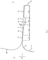
- FIG. 1 an inventive exterior trim component 10 of a motor vehicle with a coordinate system K is shown, which applies as a so-called network mostly for the entire motor vehicle.
- An in Fig. 1 drawn tool cutting line W illustrates that the problem underlying the invention burr problem is solved further inside I, as in known exterior trim components of this kind.
- a joint widening follows over a second region 32 by forming a clearance 33 running downwardly in relation to the shoulder surface 21 into a separation region 34 in which or at the beginning of which the tool separation W according to the invention is provided.
- the tool separation W is therefore arranged according to the invention in an end region of the clearance 33 or thereafter.
- the neighboring surface 12 holds an inner distance 35 from the heel surface 21.
- a recess is designed as a separating region 34.
- the inner space 35 is secured so as not to allow damage of one degree.
- a cam region 36 is provided on the inside adjacent to the separating region 34. There, the neighboring surface 12 with a cam 13 of the shoulder surface 21 opposes.
- FIG. 2 illustrated as section AA (in Fig. 3
- An outer wall begins at the top of the L-shaped connection to the more horizontal leg 11 and ends further down in a slight bend or fulcrum on target wall thickness.
- the outer wall 14 is as shown in FIG. 2 advantageous to the leg 11 out, continuously slimmering, formed. Seen from below, one can speak of a thinning 15 following the fulcrum. As facilitates the molding of the molding in manufacturing processes according to the invention.
- the leg 11 ends in an inner end region 37 with spaced through holes arranged 17.
- the through holes 17 are provided for fastening elements (not shown), which serve for attachment to the body 20.
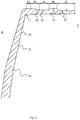
- FIGS. 3 and 4 are sections of a perspective interior view of the outer lining component 10 shown.
- the upper end is in FIG. 3 shown enlarged and registered for comparison, a surface profile of the body 20.
- the thinning 15 is sketched with its lower end in a pivot point.
- the wheel flange of a motor vehicle is recessed at the pivot point of the wall dilution.
- a T leg 18 protruding inward from the outer wall 14 is partially retracted.
- the recess 19 is covered by a wheel arch liner after assembly (not shown).
- Fig. 4 is further down on the inside I of the outer wall 14, a breakpoint 16 outlined.
- the outer lining component 10 in particular a bumper, is retained on the underside during removal from the mold in order to influence the shrinkage of material in the shrinkage direction S. Shrinkage occurs as a result of the illustrated advantageous embodiment ( Fig. 4 ) on one side down.
Landscapes
- Engineering & Computer Science (AREA)
- Mechanical Engineering (AREA)
- Chemical & Material Sciences (AREA)
- Combustion & Propulsion (AREA)
- Transportation (AREA)
- Body Structure For Vehicles (AREA)
- Motor Or Generator Frames (AREA)
- Connection Of Plates (AREA)
- Vehicle Interior And Exterior Ornaments, Soundproofing, And Insulation (AREA)
- Mounting, Exchange, And Manufacturing Of Dies (AREA)
- Superstructure Of Vehicle (AREA)
Abstract
Description
- Die Erfindung betrifft ein Außenverkleidungsbauteil eines Kraftfahrzeugs mit den oberbegrifflichen Merkmalen des Patentanspruchs 1, wie beispielsweise aus
EP 0 417 654 B1 bekannt. - Insbesondere bei einer Anbindung solcher Außenverkleidungsbauteile aus Kunststoff an ein Blech ist immer Korrosion in einem Kontaktbereich der verschiedenen Materialien festzustellen. Diesem Problem widmet sich die
EP 0 417 654 B1 . Die Anbindung erfolgt zwischen einer nach innen abgewinkelten Absatzfläche der Karosserie und einem nach innen von einem Stoßfänger abstehenden Schenkel mit einer streifenförmigen Verlängerung. Die streifenförmige Verlängerung wird in einer zusätzlichen Führungsschiene aufgenommen, welche vorangehend an der Karosserie zu befestigen ist. - Die
DE 10 2009 010 193 schlägt einen L-Schenkel vor, der als separates Element und Zwischenstück angeordnet wird. - Es ist demnach bekannt, dass die Absatzfläche und eine der Absatzfläche zugewandte Nachbarfläche des Schenkels in einem, aus Sicht auf einen Schnitt durch das Kraftfahrzeug, von außen nach innen reichenden, ersten Bereich nahezu parallel zueinander verlaufen.
- Aufgabe der Erfindung ist es, ein Außenverkleidungsbauteil zu schaffen, welches sich einfach an eine Karosserie anbinden lässt, möglichst ohne Korrosionsprobleme zu verursachen.
- Das Problem wird erfindungsgemäß gelöst durch ein Außenverkleidungsbauteil eines Kraftfahrzeugs umfassend die Merkmale des kennzeichnenden Teils des Anspruchs 1.
- Vorteilhafte Ausführungsformen sind in den Unteransprüchen angegeben.
- Gemäß der Erfindung ist von außen bis zumindest zum inneren Ende des ersten Bereichs die Nachbarfläche frei von Graten oder sonstigen, insbesondere scharfkantigen, Erhebungen ausgeführt, die beispielsweise durch eine Werkzeugtrennung bedingt sind. Auf den ersten Bereich folgend fällt die Nachbarfläche in einem zweiten Bereich von der Absatzfläche weg mit einem Freigang ab, bis hin zu einem Trennbereich, insbesondere bis hin zur Werkzeugtrennung.
- In dem Trennbereich und bevorzugt an dessen äußeren Ende, zum Freigang hin, verläuft gemäß einer bevorzugten Ausführungsform die Werkzeugtrennung. Dort ist ein innerer Abstand zwischen der Absatzfläche und der Nachbarfläche sicher eingehalten.
- Durch die Verlegung der Werkzeugtrennung nach innen entsteht bei Kontakt zwischen Außenverkleidungsteil und Blechteil keine Scheuerstelle.
- Die bei bekannten Stoßfängern, die ohne Zwischenschienen oder Schutzfolien meist mit Abstand zu einer Karosseriefläche an die Karosserie angebunden waren, oft außen, im Kontaktbereich der beiden kritischen Flächen angeordneten, aus Werkzeugtrennungen resultierenden Grate sind erfindungsgemäß nach innen versetzt und in einem größeren Abstand zum Blechteil angeordnet. Der Grat wird wegen der erfindungsgemäßen Geometrie des Außenverkleidungsbauteils den Lack eher nicht verletzen. Die störende Werkzeugtrennung, bzw. der resultierende Grat, wird nunmehr einem Kontakt zum negativen Seitenwandrahmen entzogen. Die Erfindung beinhaltet eine mit den oben genannten erfindungsgemäßen Merkmalen ausgeführte Folie oder Abdeckung für ein Außenverkleidungsbauteil.
- Gemäß einer vorteilhaften Ausführungsform eines erfindungsgemäßen Außenverkleidungsbauteils ist kein äußerer Abstand in dem ersten Bereich zwischen der Absatzfläche und der Nachbarfläche vorgesehen. Die Erfindung ermöglicht somit eine Ausbildung einer Nullfuge.
- Gemäß einer weiteren vorteilhaften Ausführungsform eines erfindungsgemäßen Außenverkleidungsbauteils hat der Freigang eine Neigung von bevorzugt und ggf. abschnittsweise etwa 7° in Bezug zu einem Koordinatensystem bzw. Netz des Kraftfahrzeugs.
- Gemäß einer weiteren vorteilhaften Ausführungsform eines erfindungsgemäßen Außenverkleidungsbauteils ist auf den Trennbereich folgend zur Innenseite hin eine Nocke angeordnet, die sich bevorzugt an die Absatzfläche anschmiegt. Eine definierte Nullfuge zwischen Stoßfänger und Seitenwandrahmen ist damit über eine ausreichende Abschnittslänge in dem ersten Bereich hinweg stabilisiert.
- Gemäß einer weiteren vorteilhaften Ausführungsform eines erfindungsgemäßen Außenverkleidungsbauteils geht die Nocke mit abgerundeten Flanken in einen zur Absatzfläche parallelen Nockenbereich über.
- Gemäß einer weiteren vorteilhaften Ausführungsform eines erfindungsgemäßen Außenverkleidungsbauteils erfolgt in einem inneren Endbereich die Anbindung an die Karosserie, insbesondere mittels eines durch ein Durchgangsloch hindurchtretenden Befestigungselements.
- Gemäß einer weiteren vorteilhaften Ausführungsform eines erfindungsgemäßen Außenverkleidungsbauteils ist eine zum Schenkel hin verlaufende Außenwand dem Schenkel zugewandt zumindest partiell ausgedünnt ausgebildet.
- Nachfolgend wird die Erfindung anhand schematischer Darstellungen näher erläutert. Es zeigen
- Fig. 1
- ein erfindungsgemäßes Außenverkleidungsbauteil, ausschnittsweise und als Konturverlauf gezeichnet, mit Nocke,
- Fig. 2
- einen Schnitt A-A durch das Außenverkleidungsbauteil aus
Fig. 1 zur Verdeutlichung der Wanddickenverläufe, - Fig. 3
- eine perspektivische Ansicht von innen auf einen oberen Abschnitt des Außenverkleidungsbauteils aus
Fig. 1 mit eingetragenem Schnitt A-A und - Fig. 4
- die perspektivische Ansicht gem.
Fig. 3 auf einen unteren Abschnitt. - In
Fig. 1 ist ein erfindungsgemäßes Außenverkleidungsbauteil 10 eines Kraftfahrzeugs mit einem Koordinatensystem K dargestellt, das als sogenanntes Netz meist für das gesamte Kraftfahrzeug gilt. Eine inFig. 1 eingezeichnete Werkzeugtrennlinie W verdeutlicht, dass die der Erfindung zugrundeliegende Gratproblematik weiter innen I gelöst wird, als bei bekannten Außenverkleidungsbauteilen solcher Art. - Von einer außen A verlaufenden Außenwand 14 des Außenverkleidungsbauteils 10, insbesondere eines Stoßfängers, nach innen I gesehen, verlaufen gemäß
Figur 1 zunächst in einem ersten Bereich 31 eine Absatzfläche 21 der Karosserie 20 und eine Nachbarfläche 12 eines nach innen abgestellten Schenkels 11 des Verkleidungsbauteils 10 in konstanter Breite aneinander anliegend und damit parallel zueinander. Sollte in der Darstellung gem.Fig. 1 ein infinitesimaler Abstand zwischen den Flächen 12, 21 erkennbar sein, soll das lediglich die Ausbildung und die Grenzen der sich begegnenden Oberflächen verdeutlichen. Tatsächlich dient die Erfindung der Ausbildung einer Nullfuge zwischen der Absatzfläche 21 und der Nachbarfläche 12. Im Bereich 31 kommt es erfindungsgemäß zu einer Anlage konstanter Breite. - An den ersten Bereich 31 angrenzend folgt über einen zweiten Bereich 32 hinweg eine Fugenaufweitung durch Ausbildung eines gegenüber der Absatzfläche 21 abfallend ausgeführten Freigangs 33 in einen Trennbereich 34, in dem oder an dessen Anfang die erfindungsgemäße Werkzeugtrennung W vorgesehen ist. Die Werkzeugtrennung W ist demnach erfindungsgemäß in einem Endbereich des Freigangs 33 oder darauf folgend angeordnet. Dort hält die Nachbarfläche 12 einen inneren Abstand 35 von der Absatzfläche 21.
- In der Nachbarfläche 12 auf den Freigang 33 folgend ist eine Vertiefung als Trennbereich 34 ausgeführt. In dem Trennbereich 34 ist der innere Abstand 35 gesichert, um keine Beschädigungen durch einen Grad zuzulassen.
- Gemäß einer besonders bevorzugten Ausführungsform ist innen benachbart zu dem Trennbereich 34 ein Nockenbereich 36 vorgesehen. Dort tritt die Nachbarfläche 12 mit einer Nocke 13 der Absatzfläche 21 entgegen.
-
Fig. 2 verdeutlicht als Schnitt A-A (inFig. 3 eingetragen) die Wanddickenverläufe eines erfindungsgemäßen Außenverkleidungsbauteils 10. Ein Außenwandverlauf beginnt oben in der L-förmigen Anschluss an den eher horizontalen Schenkel 11 und endet weiter unten in einem leichten Knick oder Drehpunkt auf Sollwandstärke. Die Außenwand 14 ist gemäß der Darstellung inFigur 2 vorteilhaft zu dem Schenkel 11 hin, kontinuierlich schlanker werdend, ausgebildet. Von unten gesehen, kann von einer auf den Drehpunkt folgenden Ausdünnung 15 gesprochen werden. Da erleichtert in erfindungsgemäßen Fertigungsverfahren das Ausformen des Formteils. - Auf der Innenseite I endet der Schenkel 11 in einem inneren Endbereich 37 mit beabstandet zueinander angeordneten Durchgangslöchern 17. Die Durchgangslöcher 17 sind für Befestigungselemente (nicht dargestellt) vorgesehen, welche zum Anbinden an die Karosserie 20 dienen.
- In den
Figuren 3 und 4 sind Ausschnitte einer perspektivischen Innenansicht auf das Außenverkleidungsbauteil 10 dargestellt. Das obere Ende ist inFigur 3 vergrößert dargestellt und zum Vergleich ein Oberflächenverlauf der Karosserie 20 eingetragen. Die Ausdünnung 15 ist mit ihrem unteren Ende in einem Drehpunkt skizziert. Im Drehpunkt der Wandverdünnung wird gemäß einer vorteilhaften Ausführungsform der Radlaufflansch eines Kraftfahrzeugs ausgespart 19. Dazu ist ein nach innen I von der Außenwand 14 abstehender T-Schenkel 18 partiell zurückgenommen. Die Aussparung 19 wird nach der Montage von einer Radlaufschale abgedeckt (nicht dargestellt). - In
Fig. 4 ist weiter unten auf der Innenseite I der Außenwand 14 ein Haltepunkt 16 skizziert. Mittels des Haltepunkts 16 wird das Außenverkleidungsbauteil 10, insbesondere ein Stoßfänger, bei der Entformung an der Unterseite festgehalten, um Materialschwund in Schwindungsrichtung S zu beeinflussen. Das Schrumpfen erfolgt als Ergebnis der dargestellten vorteilhaften Ausführungsform (Fig. 4 ) einseitig nach unten. -
- 10
- Außenverkleidungsbauteil
- 11
- Schenkel
- 12
- Nachbarfläche
- 13
- Nocke
- 14
- Außenwand
- 15
- Ausdünnung
- 16
- Haltepunkt
- 17
- Durchgangsloch
- 18
- T-Schenkel
- 19
- Aussparung
- 20
- Karosserie
- 21
- Absatzfläche
- 31
- erster Bereich
- 32
- zweiter Bereich
- 33
- Freigang
- 34
- Trennbereich
- 35
- innerer Abstand
- 36
- Nockenbereich
- 37
- innerer Endbereich
- A
- Außenseite
- I
- Innenseite
- K
- Koordinatensystem Fahrzeug
- W
- Werkzeugtrennung
- S
- Schwindungsrichtung
Claims (11)
- Außenverkleidungsbauteil (10) eines Kraftfahrzeugs, insbesondere Stoßfänger zur Anbindung an ein Blech der Außenverkleidung eines Kraftfahrzeugs, dessen Karosserie (20) eine Absatzfläche (21) für die Anbindung des Außenverkleidungsbauteils aufweist, wobei die Absatzfläche (21) von der Außenseite (A) des Kraftfahrzeugs nach innen (I) verläuft und ein ebenfalls nach innen (I) abgestellter Schenkel (11) des Außenverkleidungsbauteils (10) grob in paralleler Richtung zur Absatzfläche (21) verläuft, wobei die Absatzfläche (21) und eine der Absatzfläche (21) zugewandte Nachbarfläche (12) des Schenkels (11) in einem, aus Sicht auf einen Schnitt durch das Kraftfahrzeug, von außen (A) nach innen (I) reichenden, ersten Bereich (31) nahezu parallel zueinander verlaufen, dadurch gekennzeichnet, dass1.1 von außen (A) bis zumindest zum inneren Ende des ersten Bereichs (31) die Nachbarfläche (12) frei von Graten ist, die beispielsweise durch eine Werkzeugtrennung (W) bedingt sind, und dass1.2 die Nachbarfläche (12) auf den ersten Bereich (31) folgend, in einem zweiten Bereich (32), einen wachsenden Abstand zu der Absatzfläche (21) einnehmend, mit einem Freigang (33) abfällt, bis hin zu einem Trennbereich (34).
- Außenverkleidungsbauteil (10) nach Anspruch 1,
dadurch gekennzeichnet, dass auf den eine Freigangstasche ausbildenden Trennbereich (34) folgend zur Innenseite (I) hin eine Nocke (13) als Abstimmnocke angeordnet ist, die auf Anlage zur Absatzfläche (21) ausgeführt ist. - Außenverkleidungsbauteil (10) nach Anspruch 2,
dadurch gekennzeichnet, dass die Abstimmnocke (13) mit abgerundeten Flanken in einen zur Absatzfläche (21) parallelen Nockenbereich (36) übergeht, der sich bevorzugt über etwa 2 mm erstreckt. - Außenverkleidungsbauteil (10) nach einem der vorangehenden Ansprüche,
dadurch gekennzeichnet, dass die Werkzeugtrennung in dem Trennbereich (34) verläuft, insbesondere direkt am Ende des Freigangs (33) und ein innerer Abstand (35) zwischen der Absatzfläche (21) und der Nachbarfläche (12) eingehalten ist. - Außenverkleidungsbauteil (10) nach einem der vorangehenden Ansprüche,
dadurch gekennzeichnet, dass sich der erste Bereich (31) über etwa 2 mm erstreckt. - Außenverkleidungsbauteil (10) nach einem der vorangehenden Ansprüche,
dadurch gekennzeichnet, dass die Nachbarfläche (12) der Absatzfläche (21) angepasst in dem ersten Bereich (31) für eine Anlage an der Absatzfläche (21) und damit zur zumindest abschnittsweisen Ausbildung einer Nullfuge zwischen den Nachbarfläche (12) und der Absatzfläche (21) bestimmt sind. - Außenverkleidungsbauteil (10) nach einem der vorangehenden Ansprüche,
dadurch gekennzeichnet, dass die Nachbarfläche (12) wie auch Absatzfläche (21) in dem ersten Bereich (31), zumindest abschnittsweise, eine Neigung von etwa 3° in Bezug zu einer Achse eines Koordinatensystems (K) des Fahrzeugs aufweisen. - Außenverkleidungsbauteil (10) nach einem der vorangehenden Ansprüche,
dadurch gekennzeichnet, dass der Freigang (33) eine Neigung von zumindest abschnittsweise 7° in Bezug zur Absatzfläche (21) aufweist. - Außenverkleidungsbauteil (10) nach einem der vorangehenden Ansprüche,
dadurch gekennzeichnet, dass in einem innersten Bereich (37) die Anbindung an die Karosserie (20) erfolgt, insbesondere mittels eines durch ein Durchgangsloch (17) hindurchtretenden Befestigungselements. - Außenverkleidungsbauteil (10) nach einem der vorangehenden Ansprüche,
dadurch gekennzeichnet, dass eine zum Schenkel (11) hin verlaufende Außenwand (14) zum Schenkel (11) hin zumindest partiell ausgedünnt (15) ausgebildet ist. - Außenverkleidungsbauteil (10) nach einem der vorangehenden Ansprüche,
dadurch gekennzeichnet, dass eine zum Schenkel (11) hin verlaufende Außenwand (14) dem Schenkel (11) abgewandt einen Haltepunkt (16) aufweist.
Applications Claiming Priority (3)
| Application Number | Priority Date | Filing Date | Title |
|---|---|---|---|
| DE202013100971.7U DE202013100971U1 (de) | 2013-03-06 | 2013-03-06 | Außenverkleidungsbauteil eines Kraftfahrzeugs |
| EP13735240.7A EP2964490B1 (de) | 2013-03-06 | 2013-06-28 | Aussenverkleidungsbauteil eines kraftfahrzeugs |
| PCT/EP2013/063727 WO2014135228A1 (de) | 2013-03-06 | 2013-06-28 | Aussenverkleidungsbauteil eines kraftfahrzeugs |
Related Parent Applications (2)
| Application Number | Title | Priority Date | Filing Date |
|---|---|---|---|
| EP13735240.7A Division-Into EP2964490B1 (de) | 2013-03-06 | 2013-06-28 | Aussenverkleidungsbauteil eines kraftfahrzeugs |
| EP13735240.7A Division EP2964490B1 (de) | 2013-03-06 | 2013-06-28 | Aussenverkleidungsbauteil eines kraftfahrzeugs |
Publications (2)
| Publication Number | Publication Date |
|---|---|
| EP3222473A1 true EP3222473A1 (de) | 2017-09-27 |
| EP3222473B1 EP3222473B1 (de) | 2019-05-08 |
Family
ID=48782302
Family Applications (2)
| Application Number | Title | Priority Date | Filing Date |
|---|---|---|---|
| EP13735240.7A Active EP2964490B1 (de) | 2013-03-06 | 2013-06-28 | Aussenverkleidungsbauteil eines kraftfahrzeugs |
| EP17170535.3A Active EP3222473B1 (de) | 2013-03-06 | 2013-06-28 | Aussenverkleidungsbauteil eines kraftfahrzeugs |
Family Applications Before (1)
| Application Number | Title | Priority Date | Filing Date |
|---|---|---|---|
| EP13735240.7A Active EP2964490B1 (de) | 2013-03-06 | 2013-06-28 | Aussenverkleidungsbauteil eines kraftfahrzeugs |
Country Status (8)
| Country | Link |
|---|---|
| US (1) | US9650004B2 (de) |
| EP (2) | EP2964490B1 (de) |
| CN (1) | CN105142988B (de) |
| DE (1) | DE202013100971U1 (de) |
| ES (2) | ES2640536T3 (de) |
| HU (2) | HUE044525T2 (de) |
| MX (1) | MX367256B (de) |
| WO (1) | WO2014135228A1 (de) |
Families Citing this family (4)
| Publication number | Priority date | Publication date | Assignee | Title |
|---|---|---|---|---|
| CN105730385B (zh) * | 2016-03-14 | 2019-01-01 | 奇瑞汽车股份有限公司 | 后保险杠安装结构 |
| DE102017124440A1 (de) | 2017-10-19 | 2019-04-25 | Dr. Ing. H.C. F. Porsche Aktiengesellschaft | Strukturbauteil für eine Kraftfahrzeugkarosserie und Verfahren zur Herstellung eines Strukturbauteils |
| DE202019106075U1 (de) * | 2019-10-31 | 2021-02-02 | Rehau Ag + Co | Spritzgegossenes Außenverkleidungsteil eines Kraftfahrzeugs und Verkleidungsanordnung |
| CN117818517A (zh) * | 2022-09-28 | 2024-04-05 | 标致雪铁龙汽车股份有限公司 | 用于车辆的保险杠及包括该保险杠的车辆 |
Citations (3)
| Publication number | Priority date | Publication date | Assignee | Title |
|---|---|---|---|---|
| EP0417654B1 (de) | 1989-09-12 | 1993-11-18 | Dynamit Nobel Aktiengesellschaft | Anordung von Formteilen wie Stossfänger oder deren Verkleidungen bei Kraftfahrzeugen |
| DE19736755A1 (de) * | 1997-08-23 | 1999-02-25 | Volkswagen Ag | Befestigungsanordnung für ein gestrecktes Profilteil an einem Träger, insbesondere für eine seitliche Stoßfängerabdeckung an einem karosserieseitigen Trägerprofil |
| DE102009010193A1 (de) | 2009-02-23 | 2010-08-26 | Dr.Ing.H.C.F.Porsche Aktiengesellschaft | Stoßfängeranordnung |
Family Cites Families (9)
| Publication number | Priority date | Publication date | Assignee | Title |
|---|---|---|---|---|
| FR2440290A1 (fr) * | 1978-11-06 | 1980-05-30 | Peugeot | Dispositif de guidage des ailes laterales d'un pare-chocs sur un vehicule automobile |
| US5242200A (en) * | 1989-09-12 | 1993-09-07 | Artur Kamm | Arrangement of molded parts such as bumpers or their trim in automotive vehicles |
| JP4044184B2 (ja) * | 1997-10-21 | 2008-02-06 | 富士重工業株式会社 | バンパーモール取付構造 |
| JP2001328134A (ja) * | 2000-05-24 | 2001-11-27 | Kanegafuchi Chem Ind Co Ltd | 熱可塑性合成樹脂の型内発泡成形方法及び装置並びに型内発泡成形品 |
| JP2003182482A (ja) * | 2001-12-25 | 2003-07-03 | Suzuki Motor Corp | バンパキャップ取付構造 |
| US6641191B1 (en) * | 2002-02-07 | 2003-11-04 | General Motors Corporation | Method and apparatus for attaching cosmetic body panels to a composite truck cargo box |
| DE102006040178B3 (de) * | 2006-04-25 | 2008-11-13 | Alcan Technology & Management Ag | Profilelement zum Befestigen einer Stoßstange an Längsträgern eines Fahrzeuges |
| JP2008001207A (ja) * | 2006-06-21 | 2008-01-10 | Daikyo Nishikawa Kk | バンパーのホールカバー部材取付構造 |
| JP2008265567A (ja) * | 2007-04-20 | 2008-11-06 | Mitsubishi Fuso Truck & Bus Corp | 車両のバンパ構造及びその取付方法 |
-
2013
- 2013-03-06 DE DE202013100971.7U patent/DE202013100971U1/de not_active Expired - Lifetime
- 2013-06-28 WO PCT/EP2013/063727 patent/WO2014135228A1/de not_active Ceased
- 2013-06-28 ES ES13735240.7T patent/ES2640536T3/es active Active
- 2013-06-28 ES ES17170535T patent/ES2729181T3/es active Active
- 2013-06-28 HU HUE17170535 patent/HUE044525T2/hu unknown
- 2013-06-28 EP EP13735240.7A patent/EP2964490B1/de active Active
- 2013-06-28 US US14/772,830 patent/US9650004B2/en active Active
- 2013-06-28 HU HUE13735240A patent/HUE034761T2/en unknown
- 2013-06-28 MX MX2015011650A patent/MX367256B/es active IP Right Grant
- 2013-06-28 EP EP17170535.3A patent/EP3222473B1/de active Active
- 2013-06-28 CN CN201380075809.4A patent/CN105142988B/zh active Active
Patent Citations (3)
| Publication number | Priority date | Publication date | Assignee | Title |
|---|---|---|---|---|
| EP0417654B1 (de) | 1989-09-12 | 1993-11-18 | Dynamit Nobel Aktiengesellschaft | Anordung von Formteilen wie Stossfänger oder deren Verkleidungen bei Kraftfahrzeugen |
| DE19736755A1 (de) * | 1997-08-23 | 1999-02-25 | Volkswagen Ag | Befestigungsanordnung für ein gestrecktes Profilteil an einem Träger, insbesondere für eine seitliche Stoßfängerabdeckung an einem karosserieseitigen Trägerprofil |
| DE102009010193A1 (de) | 2009-02-23 | 2010-08-26 | Dr.Ing.H.C.F.Porsche Aktiengesellschaft | Stoßfängeranordnung |
Also Published As
| Publication number | Publication date |
|---|---|
| MX367256B (es) | 2019-08-12 |
| ES2729181T3 (es) | 2019-10-30 |
| ES2640536T3 (es) | 2017-11-03 |
| EP2964490B1 (de) | 2017-08-02 |
| CN105142988A (zh) | 2015-12-09 |
| HUE044525T2 (hu) | 2019-10-28 |
| US20160052472A1 (en) | 2016-02-25 |
| US9650004B2 (en) | 2017-05-16 |
| HUE034761T2 (en) | 2018-02-28 |
| CN105142988B (zh) | 2017-06-09 |
| WO2014135228A1 (de) | 2014-09-12 |
| MX2015011650A (es) | 2015-12-16 |
| EP3222473B1 (de) | 2019-05-08 |
| DE202013100971U1 (de) | 2014-06-12 |
| EP2964490A1 (de) | 2016-01-13 |
Similar Documents
| Publication | Publication Date | Title |
|---|---|---|
| EP2814681B1 (de) | Abdichtungsanordnung für fahrzeugscheiben, verfahren zu deren herstellung und deren verwendung | |
| EP3103665B1 (de) | Profilleiste, system und verfahren zur herstellung einer profilleiste | |
| EP3222473B1 (de) | Aussenverkleidungsbauteil eines kraftfahrzeugs | |
| EP2841217B1 (de) | Verfahren zum biegen eines verbundblechs | |
| EP1427565B1 (de) | Vorrichtung zum anbringen von dichtungsprofilen an fahrzeugtüren | |
| EP0964807B1 (de) | Rahmen zum befestigen von flächenelementen | |
| DE102015224815A1 (de) | Verfahren zur Herstellung einer Instrumententafel für ein Kraftfahrzeug | |
| EP2559609B1 (de) | Verstärkungsrahmen und Verfahren zum Anbringen eines Verstärkungsrahmens in einer Fahrzeugkarosserie | |
| EP1788182B1 (de) | Zweiteiliges tiefenverstellbares Fensterlaibungsteil, insbesondere Fensterbankteil | |
| DE102016112960A1 (de) | Verfahren zum Herstellen eines Fahrzeugdachs, Moduldach für ein Fahrzeugdach und Fahrzeugdach für ein Kraftfahrzeug | |
| EP4594074A1 (de) | Kunststoff-hohllängsträger sowie verfahren zur herstellung eines solchen kunststoff-hohllängsträgers | |
| EP2129506B1 (de) | Verfahren zur herstellung einer dichtungsanordnung, insbesondere für ein kraftfahrzeug, mit einem dichtungselement und einem träger sowie eine solche dichtungsanordnung | |
| EP3170570A1 (de) | Verfahren zur herstellung eines kraftfahrzeugbauteils sowie halbzeug aus leichtmetall | |
| DE102009010668A1 (de) | Vorrichtung und Verfahren zum Befestigen eines gummielastischen Dichtprofils, sowie Befestigungselement zur Befestigung des Dichtprofils | |
| EP2373522B1 (de) | Dachhimmel mit umgeformter, umlaufender oberkante | |
| DE102004010617A1 (de) | Verbindung zwischen einem Elastomerteil und einem Bauteil und Verfahren zum Herstellen der Verbindung | |
| EP2604475A2 (de) | Dachhimmel mit umgeformter umlaufender Oberkante | |
| EP2107976B1 (de) | Dichtung zum abdichten der fensterscheibe eines kraftfahrzeugs, verstärkungsträger für eine solche dichtung und verfahren zum herstellen der dichtung | |
| EP3652008B1 (de) | Halter für ein flächenelement einer sonnenschutz- oder verdunklungsvorrichtung und sonnenschutz- oder verdunklungsvorrichtung | |
| EP2512866B1 (de) | Vorrichtung zum fixieren eines gegenstandes in einer vertiefung | |
| DE10228974B4 (de) | Dachkonstruktion eines Fahrzeugdachs | |
| DE102015119859A1 (de) | Verfahren zur Herstellung eines Kraftfahrzeugbauteils sowie Halbzeug aus Leichtmetall | |
| DE102011113673A1 (de) | Dachhimmel mit umgeformter umlaufender Oberkante | |
| DE102008056273A1 (de) | Verfahren zur Herstellung eines geschlossenen Hohlprofils, insbesondere nach diesem Verfahren hergestelltes geschlossenes Hohlprofil sowie Vorrichtung zur Herstellung eines derartigen geschlossenen Hohlprofils | |
| WO2007079741A1 (de) | Anbindungsvorrichtung für zumindest ein führungsrohr an zumindest eine führungsschiene, insbesondere eines schiebedaches |
Legal Events
| Date | Code | Title | Description |
|---|---|---|---|
| PUAI | Public reference made under article 153(3) epc to a published international application that has entered the european phase |
Free format text: ORIGINAL CODE: 0009012 |
|
| STAA | Information on the status of an ep patent application or granted ep patent |
Free format text: STATUS: THE APPLICATION HAS BEEN PUBLISHED |
|
| AC | Divisional application: reference to earlier application |
Ref document number: 2964490 Country of ref document: EP Kind code of ref document: P |
|
| AK | Designated contracting states |
Kind code of ref document: A1 Designated state(s): AL AT BE BG CH CY CZ DE DK EE ES FI FR GB GR HR HU IE IS IT LI LT LU LV MC MK MT NL NO PL PT RO RS SE SI SK SM TR |
|
| STAA | Information on the status of an ep patent application or granted ep patent |
Free format text: STATUS: REQUEST FOR EXAMINATION WAS MADE |
|
| 17P | Request for examination filed |
Effective date: 20180314 |
|
| RBV | Designated contracting states (corrected) |
Designated state(s): AL AT BE BG CH CY CZ DE DK EE ES FI FR GB GR HR HU IE IS IT LI LT LU LV MC MK MT NL NO PL PT RO RS SE SI SK SM TR |
|
| GRAP | Despatch of communication of intention to grant a patent |
Free format text: ORIGINAL CODE: EPIDOSNIGR1 |
|
| STAA | Information on the status of an ep patent application or granted ep patent |
Free format text: STATUS: GRANT OF PATENT IS INTENDED |
|
| INTG | Intention to grant announced |
Effective date: 20181116 |
|
| GRAS | Grant fee paid |
Free format text: ORIGINAL CODE: EPIDOSNIGR3 |
|
| GRAA | (expected) grant |
Free format text: ORIGINAL CODE: 0009210 |
|
| STAA | Information on the status of an ep patent application or granted ep patent |
Free format text: STATUS: THE PATENT HAS BEEN GRANTED |
|
| AC | Divisional application: reference to earlier application |
Ref document number: 2964490 Country of ref document: EP Kind code of ref document: P |
|
| AK | Designated contracting states |
Kind code of ref document: B1 Designated state(s): AL AT BE BG CH CY CZ DE DK EE ES FI FR GB GR HR HU IE IS IT LI LT LU LV MC MK MT NL NO PL PT RO RS SE SI SK SM TR |
|
| REG | Reference to a national code |
Ref country code: GB Ref legal event code: FG4D Free format text: NOT ENGLISH |
|
| REG | Reference to a national code |
Ref country code: CH Ref legal event code: EP Ref country code: AT Ref legal event code: REF Ref document number: 1129645 Country of ref document: AT Kind code of ref document: T Effective date: 20190515 |
|
| REG | Reference to a national code |
Ref country code: DE Ref legal event code: R096 Ref document number: 502013012822 Country of ref document: DE Ref country code: IE Ref legal event code: FG4D Free format text: LANGUAGE OF EP DOCUMENT: GERMAN |
|
| REG | Reference to a national code |
Ref country code: NL Ref legal event code: MP Effective date: 20190508 |
|
| REG | Reference to a national code |
Ref country code: LT Ref legal event code: MG4D |
|
| REG | Reference to a national code |
Ref country code: HU Ref legal event code: AG4A Ref document number: E044525 Country of ref document: HU |
|
| REG | Reference to a national code |
Ref country code: ES Ref legal event code: FG2A Ref document number: 2729181 Country of ref document: ES Kind code of ref document: T3 Effective date: 20191030 |
|
| PG25 | Lapsed in a contracting state [announced via postgrant information from national office to epo] |
Ref country code: LT Free format text: LAPSE BECAUSE OF FAILURE TO SUBMIT A TRANSLATION OF THE DESCRIPTION OR TO PAY THE FEE WITHIN THE PRESCRIBED TIME-LIMIT Effective date: 20190508 Ref country code: NL Free format text: LAPSE BECAUSE OF FAILURE TO SUBMIT A TRANSLATION OF THE DESCRIPTION OR TO PAY THE FEE WITHIN THE PRESCRIBED TIME-LIMIT Effective date: 20190508 Ref country code: HR Free format text: LAPSE BECAUSE OF FAILURE TO SUBMIT A TRANSLATION OF THE DESCRIPTION OR TO PAY THE FEE WITHIN THE PRESCRIBED TIME-LIMIT Effective date: 20190508 Ref country code: SE Free format text: LAPSE BECAUSE OF FAILURE TO SUBMIT A TRANSLATION OF THE DESCRIPTION OR TO PAY THE FEE WITHIN THE PRESCRIBED TIME-LIMIT Effective date: 20190508 Ref country code: NO Free format text: LAPSE BECAUSE OF FAILURE TO SUBMIT A TRANSLATION OF THE DESCRIPTION OR TO PAY THE FEE WITHIN THE PRESCRIBED TIME-LIMIT Effective date: 20190808 Ref country code: AL Free format text: LAPSE BECAUSE OF FAILURE TO SUBMIT A TRANSLATION OF THE DESCRIPTION OR TO PAY THE FEE WITHIN THE PRESCRIBED TIME-LIMIT Effective date: 20190508 Ref country code: PT Free format text: LAPSE BECAUSE OF FAILURE TO SUBMIT A TRANSLATION OF THE DESCRIPTION OR TO PAY THE FEE WITHIN THE PRESCRIBED TIME-LIMIT Effective date: 20190908 Ref country code: FI Free format text: LAPSE BECAUSE OF FAILURE TO SUBMIT A TRANSLATION OF THE DESCRIPTION OR TO PAY THE FEE WITHIN THE PRESCRIBED TIME-LIMIT Effective date: 20190508 |
|
| PG25 | Lapsed in a contracting state [announced via postgrant information from national office to epo] |
Ref country code: BG Free format text: LAPSE BECAUSE OF FAILURE TO SUBMIT A TRANSLATION OF THE DESCRIPTION OR TO PAY THE FEE WITHIN THE PRESCRIBED TIME-LIMIT Effective date: 20190808 Ref country code: GR Free format text: LAPSE BECAUSE OF FAILURE TO SUBMIT A TRANSLATION OF THE DESCRIPTION OR TO PAY THE FEE WITHIN THE PRESCRIBED TIME-LIMIT Effective date: 20190809 Ref country code: RS Free format text: LAPSE BECAUSE OF FAILURE TO SUBMIT A TRANSLATION OF THE DESCRIPTION OR TO PAY THE FEE WITHIN THE PRESCRIBED TIME-LIMIT Effective date: 20190508 Ref country code: LV Free format text: LAPSE BECAUSE OF FAILURE TO SUBMIT A TRANSLATION OF THE DESCRIPTION OR TO PAY THE FEE WITHIN THE PRESCRIBED TIME-LIMIT Effective date: 20190508 |
|
| REG | Reference to a national code |
Ref country code: SK Ref legal event code: T3 Ref document number: E 32378 Country of ref document: SK |
|
| PG25 | Lapsed in a contracting state [announced via postgrant information from national office to epo] |
Ref country code: EE Free format text: LAPSE BECAUSE OF FAILURE TO SUBMIT A TRANSLATION OF THE DESCRIPTION OR TO PAY THE FEE WITHIN THE PRESCRIBED TIME-LIMIT Effective date: 20190508 Ref country code: DK Free format text: LAPSE BECAUSE OF FAILURE TO SUBMIT A TRANSLATION OF THE DESCRIPTION OR TO PAY THE FEE WITHIN THE PRESCRIBED TIME-LIMIT Effective date: 20190508 Ref country code: CZ Free format text: LAPSE BECAUSE OF FAILURE TO SUBMIT A TRANSLATION OF THE DESCRIPTION OR TO PAY THE FEE WITHIN THE PRESCRIBED TIME-LIMIT Effective date: 20190508 Ref country code: RO Free format text: LAPSE BECAUSE OF FAILURE TO SUBMIT A TRANSLATION OF THE DESCRIPTION OR TO PAY THE FEE WITHIN THE PRESCRIBED TIME-LIMIT Effective date: 20190508 |
|
| REG | Reference to a national code |
Ref country code: CH Ref legal event code: PL |
|
| REG | Reference to a national code |
Ref country code: DE Ref legal event code: R097 Ref document number: 502013012822 Country of ref document: DE |
|
| PG25 | Lapsed in a contracting state [announced via postgrant information from national office to epo] |
Ref country code: SM Free format text: LAPSE BECAUSE OF FAILURE TO SUBMIT A TRANSLATION OF THE DESCRIPTION OR TO PAY THE FEE WITHIN THE PRESCRIBED TIME-LIMIT Effective date: 20190508 Ref country code: MC Free format text: LAPSE BECAUSE OF FAILURE TO SUBMIT A TRANSLATION OF THE DESCRIPTION OR TO PAY THE FEE WITHIN THE PRESCRIBED TIME-LIMIT Effective date: 20190508 Ref country code: IT Free format text: LAPSE BECAUSE OF FAILURE TO SUBMIT A TRANSLATION OF THE DESCRIPTION OR TO PAY THE FEE WITHIN THE PRESCRIBED TIME-LIMIT Effective date: 20190508 |
|
| PLBE | No opposition filed within time limit |
Free format text: ORIGINAL CODE: 0009261 |
|
| STAA | Information on the status of an ep patent application or granted ep patent |
Free format text: STATUS: NO OPPOSITION FILED WITHIN TIME LIMIT |
|
| REG | Reference to a national code |
Ref country code: BE Ref legal event code: MM Effective date: 20190630 |
|
| PG25 | Lapsed in a contracting state [announced via postgrant information from national office to epo] |
Ref country code: TR Free format text: LAPSE BECAUSE OF FAILURE TO SUBMIT A TRANSLATION OF THE DESCRIPTION OR TO PAY THE FEE WITHIN THE PRESCRIBED TIME-LIMIT Effective date: 20190508 |
|
| 26N | No opposition filed |
Effective date: 20200211 |
|
| GBPC | Gb: european patent ceased through non-payment of renewal fee |
Effective date: 20190808 |
|
| PG25 | Lapsed in a contracting state [announced via postgrant information from national office to epo] |
Ref country code: PL Free format text: LAPSE BECAUSE OF FAILURE TO SUBMIT A TRANSLATION OF THE DESCRIPTION OR TO PAY THE FEE WITHIN THE PRESCRIBED TIME-LIMIT Effective date: 20190508 Ref country code: IE Free format text: LAPSE BECAUSE OF NON-PAYMENT OF DUE FEES Effective date: 20190628 |
|
| PG25 | Lapsed in a contracting state [announced via postgrant information from national office to epo] |
Ref country code: BE Free format text: LAPSE BECAUSE OF NON-PAYMENT OF DUE FEES Effective date: 20190630 Ref country code: CH Free format text: LAPSE BECAUSE OF NON-PAYMENT OF DUE FEES Effective date: 20190630 Ref country code: LI Free format text: LAPSE BECAUSE OF NON-PAYMENT OF DUE FEES Effective date: 20190630 Ref country code: SI Free format text: LAPSE BECAUSE OF FAILURE TO SUBMIT A TRANSLATION OF THE DESCRIPTION OR TO PAY THE FEE WITHIN THE PRESCRIBED TIME-LIMIT Effective date: 20190508 Ref country code: LU Free format text: LAPSE BECAUSE OF NON-PAYMENT OF DUE FEES Effective date: 20190628 |
|
| PG25 | Lapsed in a contracting state [announced via postgrant information from national office to epo] |
Ref country code: FR Free format text: LAPSE BECAUSE OF NON-PAYMENT OF DUE FEES Effective date: 20190708 |
|
| REG | Reference to a national code |
Ref country code: AT Ref legal event code: MM01 Ref document number: 1129645 Country of ref document: AT Kind code of ref document: T Effective date: 20190628 |
|
| PG25 | Lapsed in a contracting state [announced via postgrant information from national office to epo] |
Ref country code: GB Free format text: LAPSE BECAUSE OF NON-PAYMENT OF DUE FEES Effective date: 20190808 |
|
| PG25 | Lapsed in a contracting state [announced via postgrant information from national office to epo] |
Ref country code: AT Free format text: LAPSE BECAUSE OF NON-PAYMENT OF DUE FEES Effective date: 20190628 |
|
| PG25 | Lapsed in a contracting state [announced via postgrant information from national office to epo] |
Ref country code: CY Free format text: LAPSE BECAUSE OF FAILURE TO SUBMIT A TRANSLATION OF THE DESCRIPTION OR TO PAY THE FEE WITHIN THE PRESCRIBED TIME-LIMIT Effective date: 20190508 |
|
| PG25 | Lapsed in a contracting state [announced via postgrant information from national office to epo] |
Ref country code: IS Free format text: LAPSE BECAUSE OF FAILURE TO SUBMIT A TRANSLATION OF THE DESCRIPTION OR TO PAY THE FEE WITHIN THE PRESCRIBED TIME-LIMIT Effective date: 20190908 |
|
| PG25 | Lapsed in a contracting state [announced via postgrant information from national office to epo] |
Ref country code: MT Free format text: LAPSE BECAUSE OF FAILURE TO SUBMIT A TRANSLATION OF THE DESCRIPTION OR TO PAY THE FEE WITHIN THE PRESCRIBED TIME-LIMIT Effective date: 20190508 |
|
| PG25 | Lapsed in a contracting state [announced via postgrant information from national office to epo] |
Ref country code: MK Free format text: LAPSE BECAUSE OF FAILURE TO SUBMIT A TRANSLATION OF THE DESCRIPTION OR TO PAY THE FEE WITHIN THE PRESCRIBED TIME-LIMIT Effective date: 20190508 |
|
| P01 | Opt-out of the competence of the unified patent court (upc) registered |
Effective date: 20230427 |
|
| PGFP | Annual fee paid to national office [announced via postgrant information from national office to epo] |
Ref country code: DE Payment date: 20250618 Year of fee payment: 13 |
|
| PGFP | Annual fee paid to national office [announced via postgrant information from national office to epo] |
Ref country code: HU Payment date: 20250619 Year of fee payment: 13 |
|
| PGFP | Annual fee paid to national office [announced via postgrant information from national office to epo] |
Ref country code: SK Payment date: 20250624 Year of fee payment: 13 |
|
| PGFP | Annual fee paid to national office [announced via postgrant information from national office to epo] |
Ref country code: ES Payment date: 20250718 Year of fee payment: 13 |