EP3222360A1 - Zerstäuber für beschichtungsprodukt, montage- und demontageverfahren - Google Patents
Zerstäuber für beschichtungsprodukt, montage- und demontageverfahren Download PDFInfo
- Publication number
- EP3222360A1 EP3222360A1 EP17161725.1A EP17161725A EP3222360A1 EP 3222360 A1 EP3222360 A1 EP 3222360A1 EP 17161725 A EP17161725 A EP 17161725A EP 3222360 A1 EP3222360 A1 EP 3222360A1
- Authority
- EP
- European Patent Office
- Prior art keywords
- sprayer
- stator
- guiding element
- air guiding
- skirt
- Prior art date
- Legal status (The legal status is an assumption and is not a legal conclusion. Google has not performed a legal analysis and makes no representation as to the accuracy of the status listed.)
- Granted
Links
- 238000000034 method Methods 0.000 title claims description 11
- 239000011248 coating agent Substances 0.000 title description 10
- 238000000576 coating method Methods 0.000 title description 10
- 230000005291 magnetic effect Effects 0.000 claims abstract description 32
- 239000003302 ferromagnetic material Substances 0.000 claims abstract description 24
- 238000006073 displacement reaction Methods 0.000 claims description 12
- 230000000295 complement effect Effects 0.000 claims description 9
- 239000000463 material Substances 0.000 claims description 7
- 230000005294 ferromagnetic effect Effects 0.000 claims description 6
- 239000007921 spray Substances 0.000 description 13
- 241000920340 Pion Species 0.000 description 6
- 238000005507 spraying Methods 0.000 description 5
- 239000003973 paint Substances 0.000 description 4
- 238000004140 cleaning Methods 0.000 description 3
- 229910045601 alloy Inorganic materials 0.000 description 2
- 239000000956 alloy Substances 0.000 description 2
- 230000006378 damage Effects 0.000 description 2
- 230000007423 decrease Effects 0.000 description 2
- 230000000694 effects Effects 0.000 description 2
- 230000005415 magnetization Effects 0.000 description 2
- 239000002904 solvent Substances 0.000 description 2
- 210000002105 tongue Anatomy 0.000 description 2
- 239000002966 varnish Substances 0.000 description 2
- 210000000707 wrist Anatomy 0.000 description 2
- 238000000889 atomisation Methods 0.000 description 1
- 238000005520 cutting process Methods 0.000 description 1
- 230000006866 deterioration Effects 0.000 description 1
- 239000012530 fluid Substances 0.000 description 1
- 239000007788 liquid Substances 0.000 description 1
- 238000004519 manufacturing process Methods 0.000 description 1
- 229910001092 metal group alloy Inorganic materials 0.000 description 1
- 210000000056 organ Anatomy 0.000 description 1
- 230000008520 organization Effects 0.000 description 1
- 230000002093 peripheral effect Effects 0.000 description 1
- 239000000843 powder Substances 0.000 description 1
- 239000013615 primer Substances 0.000 description 1
- 239000002987 primer (paints) Substances 0.000 description 1
Images


Classifications
-
- B—PERFORMING OPERATIONS; TRANSPORTING
- B05—SPRAYING OR ATOMISING IN GENERAL; APPLYING FLUENT MATERIALS TO SURFACES, IN GENERAL
- B05B—SPRAYING APPARATUS; ATOMISING APPARATUS; NOZZLES
- B05B13/00—Machines or plants for applying liquids or other fluent materials to surfaces of objects or other work by spraying, not covered by groups B05B1/00 - B05B11/00
- B05B13/02—Means for supporting work; Arrangement or mounting of spray heads; Adaptation or arrangement of means for feeding work
- B05B13/0278—Arrangement or mounting of spray heads
-
- B—PERFORMING OPERATIONS; TRANSPORTING
- B05—SPRAYING OR ATOMISING IN GENERAL; APPLYING FLUENT MATERIALS TO SURFACES, IN GENERAL
- B05B—SPRAYING APPARATUS; ATOMISING APPARATUS; NOZZLES
- B05B3/00—Spraying or sprinkling apparatus with moving outlet elements or moving deflecting elements
- B05B3/02—Spraying or sprinkling apparatus with moving outlet elements or moving deflecting elements with rotating elements
- B05B3/10—Spraying or sprinkling apparatus with moving outlet elements or moving deflecting elements with rotating elements discharging over substantially the whole periphery of the rotating member, i.e. the spraying being effected by centrifugal forces
- B05B3/1092—Means for supplying shaping gas
-
- B—PERFORMING OPERATIONS; TRANSPORTING
- B05—SPRAYING OR ATOMISING IN GENERAL; APPLYING FLUENT MATERIALS TO SURFACES, IN GENERAL
- B05B—SPRAYING APPARATUS; ATOMISING APPARATUS; NOZZLES
- B05B3/00—Spraying or sprinkling apparatus with moving outlet elements or moving deflecting elements
- B05B3/02—Spraying or sprinkling apparatus with moving outlet elements or moving deflecting elements with rotating elements
- B05B3/04—Spraying or sprinkling apparatus with moving outlet elements or moving deflecting elements with rotating elements driven by the liquid or other fluent material discharged, e.g. the liquid actuating a motor before passing to the outlet
- B05B3/0409—Spraying or sprinkling apparatus with moving outlet elements or moving deflecting elements with rotating elements driven by the liquid or other fluent material discharged, e.g. the liquid actuating a motor before passing to the outlet with moving, e.g. rotating, outlet elements
- B05B3/0418—Spraying or sprinkling apparatus with moving outlet elements or moving deflecting elements with rotating elements driven by the liquid or other fluent material discharged, e.g. the liquid actuating a motor before passing to the outlet with moving, e.g. rotating, outlet elements comprising a liquid driven rotor, e.g. a turbine
- B05B3/0422—Spraying or sprinkling apparatus with moving outlet elements or moving deflecting elements with rotating elements driven by the liquid or other fluent material discharged, e.g. the liquid actuating a motor before passing to the outlet with moving, e.g. rotating, outlet elements comprising a liquid driven rotor, e.g. a turbine with rotating outlet elements
-
- B—PERFORMING OPERATIONS; TRANSPORTING
- B05—SPRAYING OR ATOMISING IN GENERAL; APPLYING FLUENT MATERIALS TO SURFACES, IN GENERAL
- B05B—SPRAYING APPARATUS; ATOMISING APPARATUS; NOZZLES
- B05B3/00—Spraying or sprinkling apparatus with moving outlet elements or moving deflecting elements
- B05B3/02—Spraying or sprinkling apparatus with moving outlet elements or moving deflecting elements with rotating elements
- B05B3/10—Spraying or sprinkling apparatus with moving outlet elements or moving deflecting elements with rotating elements discharging over substantially the whole periphery of the rotating member, i.e. the spraying being effected by centrifugal forces
- B05B3/1007—Spraying or sprinkling apparatus with moving outlet elements or moving deflecting elements with rotating elements discharging over substantially the whole periphery of the rotating member, i.e. the spraying being effected by centrifugal forces characterised by the rotating member
- B05B3/1014—Spraying or sprinkling apparatus with moving outlet elements or moving deflecting elements with rotating elements discharging over substantially the whole periphery of the rotating member, i.e. the spraying being effected by centrifugal forces characterised by the rotating member with a spraying edge, e.g. like a cup or a bell
-
- B—PERFORMING OPERATIONS; TRANSPORTING
- B05—SPRAYING OR ATOMISING IN GENERAL; APPLYING FLUENT MATERIALS TO SURFACES, IN GENERAL
- B05B—SPRAYING APPARATUS; ATOMISING APPARATUS; NOZZLES
- B05B13/00—Machines or plants for applying liquids or other fluent materials to surfaces of objects or other work by spraying, not covered by groups B05B1/00 - B05B11/00
- B05B13/02—Means for supporting work; Arrangement or mounting of spray heads; Adaptation or arrangement of means for feeding work
- B05B13/04—Means for supporting work; Arrangement or mounting of spray heads; Adaptation or arrangement of means for feeding work the spray heads being moved during spraying operation
- B05B13/0431—Means for supporting work; Arrangement or mounting of spray heads; Adaptation or arrangement of means for feeding work the spray heads being moved during spraying operation with spray heads moved by robots or articulated arms, e.g. for applying liquid or other fluent material to 3D-surfaces
-
- B—PERFORMING OPERATIONS; TRANSPORTING
- B05—SPRAYING OR ATOMISING IN GENERAL; APPLYING FLUENT MATERIALS TO SURFACES, IN GENERAL
- B05B—SPRAYING APPARATUS; ATOMISING APPARATUS; NOZZLES
- B05B15/00—Details of spraying plant or spraying apparatus not otherwise provided for; Accessories
- B05B15/60—Arrangements for mounting, supporting or holding spraying apparatus
-
- B—PERFORMING OPERATIONS; TRANSPORTING
- B05—SPRAYING OR ATOMISING IN GENERAL; APPLYING FLUENT MATERIALS TO SURFACES, IN GENERAL
- B05B—SPRAYING APPARATUS; ATOMISING APPARATUS; NOZZLES
- B05B17/00—Apparatus for spraying or atomising liquids or other fluent materials, not covered by the preceding groups
-
- B—PERFORMING OPERATIONS; TRANSPORTING
- B05—SPRAYING OR ATOMISING IN GENERAL; APPLYING FLUENT MATERIALS TO SURFACES, IN GENERAL
- B05B—SPRAYING APPARATUS; ATOMISING APPARATUS; NOZZLES
- B05B5/00—Electrostatic spraying apparatus; Spraying apparatus with means for charging the spray electrically; Apparatus for spraying liquids or other fluent materials by other electric means
- B05B5/025—Discharge apparatus, e.g. electrostatic spray guns
- B05B5/04—Discharge apparatus, e.g. electrostatic spray guns characterised by having rotary outlet or deflecting elements, i.e. spraying being also effected by centrifugal forces
- B05B5/0426—Means for supplying shaping gas
Definitions
- the present invention relates to a spray coating product, intended to be mounted at the end of the arm of a multi-axis robot, a manipulator back and forth more commonly called reciprocator, or stationary.
- Multi-axis robots are used especially on automobile paint lines to deposit a coating product, such as a primer, a varnish or paint.
- some sprayers are equipped with a high speed turbine, which drives a bowl in rotation about a spraying axis.
- a skirt is fixed on the stator of the turbine to diffuse an air jet inside and / or outside the cloud of coating product, so as to stabilize the cloud.
- This skirt is bipartite: it includes an inner portion and an outer portion arranged to diffuse "straight" air and / or air "vortex".
- the skirt is fixed on the body of the sprayer either by directly screwing the outer portion of the skirt on the body of the sprayer, or by means of a special nut which is screwed to the body of the sprayer and which maintains skirt by a shoulder.
- the skirt is crossed by independent circuits of compressed air. Often, these independent circuits include one or more directional air circuits, called “right” air, one or more additional air circuits, called “vortex” air, and one or more cleaning solvent circuits.
- a skirt thus comprises between five and eight independent circuits, which are connected to complementary circuits defined in the body of the sprayer.
- the skirt must therefore be positioned angularly relative to the body of the sprayer in a predefined manner. This predefined angular position is maintained by an additional component, such as a radial pin.
- the radial pin makes cleaning operations complicated and laborious because many seals must be changed periodically.
- the invention particularly intends to remedy by proposing a coating product sprayer with which the successive assembly and disassembly operations of the skirt do not deteriorate the sprayer components.
- US 2003/234299 A1 discloses several embodiments of a coating product sprayer.
- the sprayer comprises a body defining a receiving portion of a spray unit and a receiving portion of a cartridge.
- This sprayer is specific in that it comprises magnetic fixing means for fixing the cartridge inside the portion of the body.
- These magnetic fastening means may comprise permanent magnets or electromagnets.
- the spraying unit comprises an air guiding element defining air ejection holes.
- the cartridge is intended to be replaced and is therefore completely removable. It can not therefore be considered as a fixed member of the sprayer within the meaning of the invention.
- the magnetic fastening means mentioned in this publication serve to fix the cartridge within the portion provided in the body, and not to fix the air guide element with the fixed body of the sprayer.
- WO 2015/191323 A1 discloses several embodiments of a spray head for a spray device.
- the spray head includes a nozzle defining a fluid ejection passage and an air guide member, which includes two diametrically opposed horns, for generating atomizing air jets.
- the spray head is attached to a gun body.
- the gun comprises a pair of elastic tongues provided with respective openings. When the gun body and the spray head are engaged with each other, the resilient tongues are resiliently deformed outwardly until stops on the spray head penetrate the openings. . It is indicated on page 7, lines 27 to 30, that such fixing means could be replaced by magnets.
- the magnets mentioned in this passage of the description do not form means for fixing the air guide element on a fixed member of the sprayer. Indeed, the magnets concern the fixing of the spray head on the gun body. Moreover, the stops are provided on a barrel on which is fixed the air guide element. In particular, the air guide element can be fixed rigidly or pivotally on the barrel. In addition, the disclosed material applies more particularly to a manual application gun a coating product, not a sprayer to be mounted on a robot.
- the air guide element can be mounted and removed without risk of damaging the sprayer components because no threading is used.
- the invention also relates to a method of mounting an air guiding element on a fixed member of a sprayer as described above. This method involves moving the air guiding member and the fixed member relative to each other until reaching a position in which the air guiding member is attached to the member. fixed by cooperation of the magnetic attraction means with the piece of ferromagnetic material.
- the invention finally relates to a method of disassembly of an air guide element relative to a fixed member of a sprayer as described above.
- the method consists of moving the air guiding element and the fixed member relative to one another until it reaches a position in which the magnetic attraction means no longer cooperates with the piece of material ferromagnetic.
- the relative displacement between the guide member and the fixed member is a displacement in translation along the central axis and a tool provided with a wedge is used to move the guide element and the member axially fixed to one another during disassembly.
- the sprayer 1 is an electrostatic sprayer.
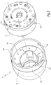
- a shoulder 20 decreases the outer diameter of the stator 2 of the turbine going forward.
- the turbine stator 2 delimits a central bore 22 for receiving the rotor.
- the shoulder 20 of the stator 2 defines an annular surface perpendicular to the axis X-X '. This annular surface comprises at least one recess 24, in which is received a magnetic attraction means 6.
- this magnetic attraction means is a permanent magnet.
- the stator 2 comprises at least one pin which protrudes radially outwards with respect to its outer surface of the stator 2.
- the stator 2 comprises three pins, among which two pins are referenced 26a and a pin is referenced 26b.
- the two pawns 26a are the pawns that are the least spaced apart from each other. Only one of these two pieces 26a is visible at the figure 2 .
- the pins 26a and 26b are distributed irregularly around the axis X-X '.
- An air guide element 4 is fixed on a fixed member of the sprayer 1.
- this element is a skirt and the stationary member is the stator 2 of the turbine.
- the skirt comprises an inner portion 4a and an outer portion 4b screwed around the inner portion 4a.
- the skirt 4 is monobloc.
- the skirt 4 has a geometry of revolution about the axis X-X '.
- the inner portion 4b of the skirt 4 has a shoulder 40 complementary to the shoulder 20 of the stator 2 of the turbine.
- the shoulder 40 decreases the inside diameter of the skirt 4 in the forward direction.
- each notch 42a or 42b extends in a helical direction around the central axis X-X ', with a helix angle ⁇ of between 5 ° and 75 °, in particular of the order of 60 °.
- This angle ⁇ is measured with respect to a direction orthoradial to the X-X 'axis.
- the pitch of each notch 42a and 42b around the axis XX ' is on the right seen from the opposite side to the fixed member 2, that is to say seen from the left to figures 1 and 3 . This implies that it is necessary to rotate the skirt 4 to the left seen from the opposite side to the fixed member 2 to fix together the skirt 4 and the fixed member 2. Alternatively not shown, this step can be left seen from the opposite side to the fixed member 2.
- the skirt 4 can also be mounted automatically using the movement of the multi-axis robot.
- the skirt 4 is mounted on a support on which it is immobilized in rotation about its axis X-X ', but free in translation along its axis X-X'.
- the skirt 4 can also be locked in translation.
- An example of a support is a column, inside which the skirt 4 is received.
- the multiaxis robot brings the fixed member 2 into a configuration in which each pin 26a and 26b is facing at a corresponding notch 42a and 42b and rotates around the central axis XX 'to engage each of the pins 26a and 26b within the corresponding notch.
- the relative displacement between the guide member 4 and the fixed member 2 is a displacement both in translation along the central axis X-X 'and in rotation around the central axis X-X'.
- FIG 4 On the figure 4 is shown a second embodiment of a sprayer according to the invention.
- the sprayer elements of this second mode which are comparable to those of the first embodiment bear identical reference numerals to those used previously, but followed by a premium (').
- the skirt 4 ' delimits one or more notches 42' which each extend parallel to the central axis X-X '.
- a specific tool is used, in particular a clamp, comprising two edges 100A and 100B.
- Each of the mounts 100A and 100B comprises at least one bevel 102, in particular two bevels 102 and 104, intended to cooperate with inclined surfaces, respectively of the skirt 4 'and the body 3 of the sprayer 1.
- the bites 100A and 100B are positioned diametrically opposite the sprayer 1 and are moved radially towards each other in a space between the skirt 4 and the body 3 of the sprayer 1, as represented by the arrows F1 at the figure 4 .
- the tool can be manipulated by an operator or a PLC.
- the skirt 4 is fixed directly to the body 3 of the sprayer, by fastening means comparable to those described above.
- the turbine does not have independent circuits 28.
- the compressed air then circulates, for example, in channels formed between the skirt 4 and the stator 2 of the turbine.
- each magnet 6 is carried by the skirt 4, while each piece of ferromagnetic material 8 is carried by the stator of the turbine 2 or by the body of the sprayer 3, according to the embodiment considered.
- the skirt 4 or the stator 2 are made of ferromagnetic material, especially in a non-magnetized ferromagnetic alloy.
- a ring is rotatably mounted around the narrowed diameter portion of the stator 2 of the turbine.
- this ring comprises several magnets distributed with alternating polarities in a peripheral direction around the central axis of the ring.
- the ring therefore does not exert the same magnetic effect regardless of its angular position. Indeed, depending on the angular position of the ring, it can either attract ferromagnetic elements or repel.
- the skirt 4 In mounted configuration of the skirt 4 on the body 2, it is then sufficient to pivot the ring around the body 2 to push the skirt 4 of the body 2, which facilitates the disassembly of the skirt 4.
- the disassembly of the skirt 4 can be effected by means of a strap wrench.
Landscapes
- Engineering & Computer Science (AREA)
- Robotics (AREA)
- Electrostatic Spraying Apparatus (AREA)
- Details Or Accessories Of Spraying Plant Or Apparatus (AREA)
- Nozzles (AREA)
- Spray Control Apparatus (AREA)
- Application Of Or Painting With Fluid Materials (AREA)
- Special Spraying Apparatus (AREA)
- Turbine Rotor Nozzle Sealing (AREA)
Priority Applications (1)
| Application Number | Priority Date | Filing Date | Title |
|---|---|---|---|
| PL17161725T PL3222360T3 (pl) | 2016-03-21 | 2017-03-20 | Opryskiwacz produktem powlekającym, sposób montażu i demontażu |
Applications Claiming Priority (1)
| Application Number | Priority Date | Filing Date | Title |
|---|---|---|---|
| FR1652390A FR3048896B1 (fr) | 2016-03-21 | 2016-03-21 | Pulverisateur de produit de revetement, procede de montage et de demontage |
Publications (2)
| Publication Number | Publication Date |
|---|---|
| EP3222360A1 true EP3222360A1 (de) | 2017-09-27 |
| EP3222360B1 EP3222360B1 (de) | 2019-01-02 |
Family
ID=56069109
Family Applications (1)
| Application Number | Title | Priority Date | Filing Date |
|---|---|---|---|
| EP17161725.1A Active EP3222360B1 (de) | 2016-03-21 | 2017-03-20 | Zerstäuber für beschichtungsprodukt, montage- und demontageverfahren |
Country Status (13)
| Country | Link |
|---|---|
| US (1) | US11534777B2 (de) |
| EP (1) | EP3222360B1 (de) |
| JP (1) | JP6974016B2 (de) |
| KR (1) | KR102385123B1 (de) |
| CN (1) | CN107214028A (de) |
| BR (1) | BR102017004740A2 (de) |
| DK (1) | DK3222360T3 (de) |
| ES (1) | ES2712927T3 (de) |
| FR (1) | FR3048896B1 (de) |
| PL (1) | PL3222360T3 (de) |
| PT (1) | PT3222360T (de) |
| RU (1) | RU2725431C2 (de) |
| TR (1) | TR201904233T4 (de) |
Cited By (1)
| Publication number | Priority date | Publication date | Assignee | Title |
|---|---|---|---|---|
| FR3127535A1 (fr) * | 2021-09-29 | 2023-03-31 | Exel Industries | Dispositif de fixation de pulvérisateur sur un bras robotisé |
Families Citing this family (2)
| Publication number | Priority date | Publication date | Assignee | Title |
|---|---|---|---|---|
| FR3083722B1 (fr) * | 2018-07-13 | 2020-10-09 | Exel Ind | Turbine pour dispositif de projection de fluide, dispositif de projection de fluide, ainsi qu'ensemble comprenant un tel dispositif et un outil |
| US11911783B2 (en) * | 2020-09-21 | 2024-02-27 | Scale Up The Fun, Llc | Fluid spray gun |
Citations (4)
| Publication number | Priority date | Publication date | Assignee | Title |
|---|---|---|---|---|
| US20030234299A1 (en) | 2001-08-09 | 2003-12-25 | Toshio Hosoda | Cartridge type coater |
| DE102004032045A1 (de) * | 2004-07-02 | 2006-01-26 | J. Wagner Ag | Rotationszerstäuber |
| US20150258554A1 (en) * | 2014-03-14 | 2015-09-17 | Gunnar van der Steur | Rotary atomizer edge guard |
| WO2015191323A1 (en) | 2014-06-10 | 2015-12-17 | 3M Innovative Properties Company | Nozzle assembly with external baffles |
Family Cites Families (21)
| Publication number | Priority date | Publication date | Assignee | Title |
|---|---|---|---|---|
| JPS5872299A (ja) | 1981-10-23 | 1983-04-30 | 株式会社山武 | ダンピング回路 |
| SU1214228A1 (ru) | 1984-08-08 | 1986-02-28 | Всесоюзный Научно-Исследовательский Биотехнический Институт | Центробежный распылитель жидкости |
| AU4141889A (en) | 1988-10-20 | 1990-04-26 | Nordson Corporation | Powder or solid particulate material spray gun |
| US5078321A (en) | 1990-06-22 | 1992-01-07 | Nordson Corporation | Rotary atomizer cup |
| SE507891C2 (sv) | 1992-04-23 | 1998-07-27 | Fischer Ag E | Sprutmålningsmunstycke |
| WO1999036182A1 (fr) * | 1998-01-13 | 1999-07-22 | Abb K.K. | Dispositif de revetement de type tete de pulverisation rotative |
| FR2805182B1 (fr) | 2000-02-21 | 2002-09-20 | Sames Sa | Dispositif de projection de produit de revetement comprenant un element rotatif de pulverisation |
| FR2812567B1 (fr) | 2000-08-07 | 2003-03-07 | Sames Sa | Dispositif de projection de produit de revetement comprenant une buse |
| AU2003276336A1 (en) | 2002-09-13 | 2004-04-30 | Sames Technologies | Spray bowl, discharge device comprising one such bowl and discharge installation comprising one such device |
| EP1711269B1 (de) | 2004-02-06 | 2008-03-26 | SAMES Technologies | Sprühglocke für einen rotationszerstäuber mit magnetischer befestigung |
| FR2874518B1 (fr) | 2004-08-25 | 2006-12-22 | Sames Technologies Soc Par Act | Projecteur rotatif de produit de revetement, installation comprenant un tel projecteur et methode de verification du fonctionnement d'un tel projecteur |
| US7654472B2 (en) * | 2005-10-21 | 2010-02-02 | Durr Systems, Inc. | Rotary atomizer with a spraying body |
| GB0625583D0 (en) | 2006-12-21 | 2007-01-31 | Itw Ltd | Paint spray apparatus |
| JP5183163B2 (ja) | 2007-11-16 | 2013-04-17 | 旭サナック株式会社 | 回転霧化頭 |
| DE102009013979A1 (de) | 2009-03-19 | 2010-09-23 | Dürr Systems GmbH | Elektrodenanordnung für einen elektrostatischen Zerstäuber |
| FR2945461B1 (fr) | 2009-05-13 | 2012-10-05 | Sames Technologies | Projecteur et organe de pulverisation de produit de revetement et procede de projection mettant en oeuvre un tel projecteur. |
| RU101944U1 (ru) | 2010-10-14 | 2011-02-10 | Владимир Михайлович Тарасов | Распыляющее устройство |
| US8608502B2 (en) * | 2012-05-08 | 2013-12-17 | Otter Products, Llc | Connection mechanism |
| DE102013223688A1 (de) * | 2013-11-20 | 2015-05-21 | Siemens Aktiengesellschaft | Verfahren und Vorrichtung zum automatisierten Aufbringen einer Spritzbeschichtung |
| JP6789987B2 (ja) | 2015-05-27 | 2020-11-25 | スリーエム イノベイティブ プロパティズ カンパニー | 補助開口を備える噴霧装置 |
| JP7036681B2 (ja) | 2018-06-25 | 2022-03-15 | 大同プラント工業株式会社 | 熱処理炉 |
-
2016
- 2016-03-21 FR FR1652390A patent/FR3048896B1/fr not_active Expired - Fee Related
-
2017
- 2017-03-01 US US15/446,383 patent/US11534777B2/en active Active
- 2017-03-09 BR BR102017004740-7A patent/BR102017004740A2/pt not_active Application Discontinuation
- 2017-03-16 JP JP2017051168A patent/JP6974016B2/ja active Active
- 2017-03-20 PT PT17161725T patent/PT3222360T/pt unknown
- 2017-03-20 RU RU2017109085A patent/RU2725431C2/ru active
- 2017-03-20 ES ES17161725T patent/ES2712927T3/es active Active
- 2017-03-20 EP EP17161725.1A patent/EP3222360B1/de active Active
- 2017-03-20 TR TR2019/04233T patent/TR201904233T4/tr unknown
- 2017-03-20 KR KR1020170034894A patent/KR102385123B1/ko active IP Right Grant
- 2017-03-20 CN CN201710164312.XA patent/CN107214028A/zh active Pending
- 2017-03-20 PL PL17161725T patent/PL3222360T3/pl unknown
- 2017-03-20 DK DK17161725.1T patent/DK3222360T3/en active
Patent Citations (4)
| Publication number | Priority date | Publication date | Assignee | Title |
|---|---|---|---|---|
| US20030234299A1 (en) | 2001-08-09 | 2003-12-25 | Toshio Hosoda | Cartridge type coater |
| DE102004032045A1 (de) * | 2004-07-02 | 2006-01-26 | J. Wagner Ag | Rotationszerstäuber |
| US20150258554A1 (en) * | 2014-03-14 | 2015-09-17 | Gunnar van der Steur | Rotary atomizer edge guard |
| WO2015191323A1 (en) | 2014-06-10 | 2015-12-17 | 3M Innovative Properties Company | Nozzle assembly with external baffles |
Cited By (2)
| Publication number | Priority date | Publication date | Assignee | Title |
|---|---|---|---|---|
| FR3127535A1 (fr) * | 2021-09-29 | 2023-03-31 | Exel Industries | Dispositif de fixation de pulvérisateur sur un bras robotisé |
| EP4159321A1 (de) | 2021-09-29 | 2023-04-05 | Exel Industries | Vorrichtung zur befestigung eines zerstäubers an einem roboterarm |
Also Published As
| Publication number | Publication date |
|---|---|
| KR20170109500A (ko) | 2017-09-29 |
| EP3222360B1 (de) | 2019-01-02 |
| FR3048896B1 (fr) | 2018-04-13 |
| JP2017170436A (ja) | 2017-09-28 |
| RU2017109085A3 (de) | 2020-05-22 |
| PL3222360T3 (pl) | 2019-06-28 |
| KR102385123B1 (ko) | 2022-04-11 |
| US11534777B2 (en) | 2022-12-27 |
| DK3222360T3 (en) | 2019-02-25 |
| BR102017004740A2 (pt) | 2017-12-12 |
| TR201904233T4 (tr) | 2019-05-21 |
| ES2712927T3 (es) | 2019-05-16 |
| JP6974016B2 (ja) | 2021-12-01 |
| PT3222360T (pt) | 2019-04-29 |
| CN107214028A (zh) | 2017-09-29 |
| US20170266672A1 (en) | 2017-09-21 |
| RU2725431C2 (ru) | 2020-07-02 |
| FR3048896A1 (fr) | 2017-09-22 |
| RU2017109085A (ru) | 2018-09-20 |
Similar Documents
| Publication | Publication Date | Title |
|---|---|---|
| EP3222360B1 (de) | Zerstäuber für beschichtungsprodukt, montage- und demontageverfahren | |
| CA2399624C (fr) | Dispositif de projection de produit de revetement et element rotatif de pulverisation pour un tel dispositif | |
| JP6889654B2 (ja) | ワーク回転装置及びそれを用いた塗装方法 | |
| EP1711269B1 (de) | Sprühglocke für einen rotationszerstäuber mit magnetischer befestigung | |
| EP0053543B1 (de) | Anordnungen zum Befestigen von Gegenständen an Blechen, welche nur von einer Seite her zugänglich sind | |
| EP2496849B1 (de) | Selbstblockierende schraubfixiervorrichtung und anordnung damit | |
| CA2607875A1 (fr) | Dispositif de galet tendeur ou enrouleur | |
| FR2698564A1 (fr) | Dispositif de projection de produit de revêtement à élément rotatif de pulvérisation et outil pour le montage et le démontage d'un tel élément rotatif. | |
| FR3035928A1 (fr) | Dispositif de poulie pour galet tendeur ou enrouleur | |
| EP2429716A1 (de) | Sprüheinrichtung und glied zum spritzen eines beschichtungsmaterials und solch ein spritzverfahren verwendende spritzvorrichtung | |
| FR3037115A1 (fr) | Dispositif de poulie pour galet tendeur ou enrouleur | |
| FR3103718A1 (fr) | Projecteur électrostatique rotatif de produit de revêtement et installation de projection comprenant un tel projecteur | |
| FR3029457A1 (fr) | Ensemble comportant une jante et un enjoliveur equipe d’un moyeu de blocage axial | |
| EP2142307A1 (de) | Sprühelement, sprühvorrichtung mit einem solchen element und sprühanlage mit einer solchen vorrichtung | |
| EP4159321B1 (de) | Vorrichtung zur befestigung eines zerstäubers an einem roboterarm | |
| FR3010460A1 (fr) | Injecteur hydraulique de turbine pelton et methode de demontage partiel d'un tel injecteur | |
| WO2022184785A1 (fr) | Système de butée pour outil de chauffage par contact direct | |
| FR2852368A1 (fr) | Roulement immobilise dans un logement au moyen d'un organe deplacable reversiblement | |
| FR2793729A1 (fr) | Dispositif enjoliveur a ecran publicitaire monte sur une jante d'une roue de vehicule | |
| FR3122458A1 (fr) | Dispositif de fixation réversible par emboitement coaxial à encliquetage de deux éléments | |
| FR2894310A1 (fr) | Moyeu roue libre | |
| WO1995000250A1 (fr) | Projecteur electrostatique de produit de revetement pulverulent comportant une tete de projection rotative | |
| EP1713617A1 (de) | Halterung und rotationselement, insbesondere schleifscheibe, zur abnehmbaren montage auf einer motorwelle | |
| FR2943306A1 (fr) | Systeme de montage d'un dispositif d'eclairage dans un logement d'un vehicule automobile |
Legal Events
| Date | Code | Title | Description |
|---|---|---|---|
| PUAI | Public reference made under article 153(3) epc to a published international application that has entered the european phase |
Free format text: ORIGINAL CODE: 0009012 |
|
| STAA | Information on the status of an ep patent application or granted ep patent |
Free format text: STATUS: THE APPLICATION HAS BEEN PUBLISHED |
|
| AK | Designated contracting states |
Kind code of ref document: A1 Designated state(s): AL AT BE BG CH CY CZ DE DK EE ES FI FR GB GR HR HU IE IS IT LI LT LU LV MC MK MT NL NO PL PT RO RS SE SI SK SM TR |
|
| AX | Request for extension of the european patent |
Extension state: BA ME |
|
| STAA | Information on the status of an ep patent application or granted ep patent |
Free format text: STATUS: REQUEST FOR EXAMINATION WAS MADE |
|
| 17P | Request for examination filed |
Effective date: 20180305 |
|
| RBV | Designated contracting states (corrected) |
Designated state(s): AL AT BE BG CH CY CZ DE DK EE ES FI FR GB GR HR HU IE IS IT LI LT LU LV MC MK MT NL NO PL PT RO RS SE SI SK SM TR |
|
| GRAP | Despatch of communication of intention to grant a patent |
Free format text: ORIGINAL CODE: EPIDOSNIGR1 |
|
| STAA | Information on the status of an ep patent application or granted ep patent |
Free format text: STATUS: GRANT OF PATENT IS INTENDED |
|
| INTG | Intention to grant announced |
Effective date: 20180802 |
|
| GRAS | Grant fee paid |
Free format text: ORIGINAL CODE: EPIDOSNIGR3 |
|
| GRAA | (expected) grant |
Free format text: ORIGINAL CODE: 0009210 |
|
| STAA | Information on the status of an ep patent application or granted ep patent |
Free format text: STATUS: THE PATENT HAS BEEN GRANTED |
|
| AK | Designated contracting states |
Kind code of ref document: B1 Designated state(s): AL AT BE BG CH CY CZ DE DK EE ES FI FR GB GR HR HU IE IS IT LI LT LU LV MC MK MT NL NO PL PT RO RS SE SI SK SM TR |
|
| REG | Reference to a national code |
Ref country code: GB Ref legal event code: FG4D Free format text: NOT ENGLISH |
|
| REG | Reference to a national code |
Ref country code: CH Ref legal event code: EP Ref country code: AT Ref legal event code: REF Ref document number: 1083695 Country of ref document: AT Kind code of ref document: T Effective date: 20190115 |
|
| REG | Reference to a national code |
Ref country code: IE Ref legal event code: FG4D Free format text: LANGUAGE OF EP DOCUMENT: FRENCH |
|
| REG | Reference to a national code |
Ref country code: DE Ref legal event code: R096 Ref document number: 602017001621 Country of ref document: DE |
|
| REG | Reference to a national code |
Ref country code: CH Ref legal event code: NV Representative=s name: MICHELI AND CIE SA, CH |
|
| REG | Reference to a national code |
Ref country code: DK Ref legal event code: T3 Effective date: 20190218 |
|
| REG | Reference to a national code |
Ref country code: NL Ref legal event code: FP |
|
| REG | Reference to a national code |
Ref country code: RO Ref legal event code: EPE |
|
| REG | Reference to a national code |
Ref country code: SE Ref legal event code: TRGR |
|
| REG | Reference to a national code |
Ref country code: PT Ref legal event code: SC4A Ref document number: 3222360 Country of ref document: PT Date of ref document: 20190429 Kind code of ref document: T Free format text: AVAILABILITY OF NATIONAL TRANSLATION Effective date: 20190402 |
|
| REG | Reference to a national code |
Ref country code: ES Ref legal event code: FG2A Ref document number: 2712927 Country of ref document: ES Kind code of ref document: T3 Effective date: 20190516 |
|
| REG | Reference to a national code |
Ref country code: LT Ref legal event code: MG4D |
|
| REG | Reference to a national code |
Ref country code: AT Ref legal event code: MK05 Ref document number: 1083695 Country of ref document: AT Kind code of ref document: T Effective date: 20190102 |
|
| PG25 | Lapsed in a contracting state [announced via postgrant information from national office to epo] |
Ref country code: FI Free format text: LAPSE BECAUSE OF FAILURE TO SUBMIT A TRANSLATION OF THE DESCRIPTION OR TO PAY THE FEE WITHIN THE PRESCRIBED TIME-LIMIT Effective date: 20190102 Ref country code: LT Free format text: LAPSE BECAUSE OF FAILURE TO SUBMIT A TRANSLATION OF THE DESCRIPTION OR TO PAY THE FEE WITHIN THE PRESCRIBED TIME-LIMIT Effective date: 20190102 Ref country code: NO Free format text: LAPSE BECAUSE OF FAILURE TO SUBMIT A TRANSLATION OF THE DESCRIPTION OR TO PAY THE FEE WITHIN THE PRESCRIBED TIME-LIMIT Effective date: 20190402 |
|
| PG25 | Lapsed in a contracting state [announced via postgrant information from national office to epo] |
Ref country code: GR Free format text: LAPSE BECAUSE OF FAILURE TO SUBMIT A TRANSLATION OF THE DESCRIPTION OR TO PAY THE FEE WITHIN THE PRESCRIBED TIME-LIMIT Effective date: 20190403 Ref country code: HR Free format text: LAPSE BECAUSE OF FAILURE TO SUBMIT A TRANSLATION OF THE DESCRIPTION OR TO PAY THE FEE WITHIN THE PRESCRIBED TIME-LIMIT Effective date: 20190102 Ref country code: LV Free format text: LAPSE BECAUSE OF FAILURE TO SUBMIT A TRANSLATION OF THE DESCRIPTION OR TO PAY THE FEE WITHIN THE PRESCRIBED TIME-LIMIT Effective date: 20190102 Ref country code: IS Free format text: LAPSE BECAUSE OF FAILURE TO SUBMIT A TRANSLATION OF THE DESCRIPTION OR TO PAY THE FEE WITHIN THE PRESCRIBED TIME-LIMIT Effective date: 20190502 Ref country code: BG Free format text: LAPSE BECAUSE OF FAILURE TO SUBMIT A TRANSLATION OF THE DESCRIPTION OR TO PAY THE FEE WITHIN THE PRESCRIBED TIME-LIMIT Effective date: 20190402 Ref country code: RS Free format text: LAPSE BECAUSE OF FAILURE TO SUBMIT A TRANSLATION OF THE DESCRIPTION OR TO PAY THE FEE WITHIN THE PRESCRIBED TIME-LIMIT Effective date: 20190102 |
|
| REG | Reference to a national code |
Ref country code: DE Ref legal event code: R097 Ref document number: 602017001621 Country of ref document: DE |
|
| PG25 | Lapsed in a contracting state [announced via postgrant information from national office to epo] |
Ref country code: AT Free format text: LAPSE BECAUSE OF FAILURE TO SUBMIT A TRANSLATION OF THE DESCRIPTION OR TO PAY THE FEE WITHIN THE PRESCRIBED TIME-LIMIT Effective date: 20190102 Ref country code: EE Free format text: LAPSE BECAUSE OF FAILURE TO SUBMIT A TRANSLATION OF THE DESCRIPTION OR TO PAY THE FEE WITHIN THE PRESCRIBED TIME-LIMIT Effective date: 20190102 Ref country code: AL Free format text: LAPSE BECAUSE OF FAILURE TO SUBMIT A TRANSLATION OF THE DESCRIPTION OR TO PAY THE FEE WITHIN THE PRESCRIBED TIME-LIMIT Effective date: 20190102 Ref country code: MC Free format text: LAPSE BECAUSE OF FAILURE TO SUBMIT A TRANSLATION OF THE DESCRIPTION OR TO PAY THE FEE WITHIN THE PRESCRIBED TIME-LIMIT Effective date: 20190102 |
|
| PLBE | No opposition filed within time limit |
Free format text: ORIGINAL CODE: 0009261 |
|
| STAA | Information on the status of an ep patent application or granted ep patent |
Free format text: STATUS: NO OPPOSITION FILED WITHIN TIME LIMIT |
|
| PG25 | Lapsed in a contracting state [announced via postgrant information from national office to epo] |
Ref country code: LU Free format text: LAPSE BECAUSE OF NON-PAYMENT OF DUE FEES Effective date: 20190320 Ref country code: SM Free format text: LAPSE BECAUSE OF FAILURE TO SUBMIT A TRANSLATION OF THE DESCRIPTION OR TO PAY THE FEE WITHIN THE PRESCRIBED TIME-LIMIT Effective date: 20190102 |
|
| 26N | No opposition filed |
Effective date: 20191003 |
|
| REG | Reference to a national code |
Ref country code: BE Ref legal event code: MM Effective date: 20190331 |
|
| PG25 | Lapsed in a contracting state [announced via postgrant information from national office to epo] |
Ref country code: IE Free format text: LAPSE BECAUSE OF NON-PAYMENT OF DUE FEES Effective date: 20190320 |
|
| PG25 | Lapsed in a contracting state [announced via postgrant information from national office to epo] |
Ref country code: SI Free format text: LAPSE BECAUSE OF FAILURE TO SUBMIT A TRANSLATION OF THE DESCRIPTION OR TO PAY THE FEE WITHIN THE PRESCRIBED TIME-LIMIT Effective date: 20190102 Ref country code: BE Free format text: LAPSE BECAUSE OF NON-PAYMENT OF DUE FEES Effective date: 20190331 |
|
| PGFP | Annual fee paid to national office [announced via postgrant information from national office to epo] |
Ref country code: SE Payment date: 20200327 Year of fee payment: 4 Ref country code: DK Payment date: 20200227 Year of fee payment: 4 Ref country code: RO Payment date: 20200225 Year of fee payment: 4 Ref country code: PL Payment date: 20200217 Year of fee payment: 4 Ref country code: NL Payment date: 20200227 Year of fee payment: 4 Ref country code: PT Payment date: 20200217 Year of fee payment: 4 |
|
| PGFP | Annual fee paid to national office [announced via postgrant information from national office to epo] |
Ref country code: CZ Payment date: 20200219 Year of fee payment: 4 Ref country code: SK Payment date: 20200218 Year of fee payment: 4 |
|
| PG25 | Lapsed in a contracting state [announced via postgrant information from national office to epo] |
Ref country code: MT Free format text: LAPSE BECAUSE OF FAILURE TO SUBMIT A TRANSLATION OF THE DESCRIPTION OR TO PAY THE FEE WITHIN THE PRESCRIBED TIME-LIMIT Effective date: 20190102 |
|
| PG25 | Lapsed in a contracting state [announced via postgrant information from national office to epo] |
Ref country code: CY Free format text: LAPSE BECAUSE OF FAILURE TO SUBMIT A TRANSLATION OF THE DESCRIPTION OR TO PAY THE FEE WITHIN THE PRESCRIBED TIME-LIMIT Effective date: 20190102 |
|
| PG25 | Lapsed in a contracting state [announced via postgrant information from national office to epo] |
Ref country code: HU Free format text: LAPSE BECAUSE OF FAILURE TO SUBMIT A TRANSLATION OF THE DESCRIPTION OR TO PAY THE FEE WITHIN THE PRESCRIBED TIME-LIMIT; INVALID AB INITIO Effective date: 20170320 |
|
| PG25 | Lapsed in a contracting state [announced via postgrant information from national office to epo] |
Ref country code: CZ Free format text: LAPSE BECAUSE OF NON-PAYMENT OF DUE FEES Effective date: 20210320 |
|
| REG | Reference to a national code |
Ref country code: DK Ref legal event code: EBP Effective date: 20210331 |
|
| REG | Reference to a national code |
Ref country code: NL Ref legal event code: MM Effective date: 20210401 |
|
| REG | Reference to a national code |
Ref country code: SK Ref legal event code: MM4A Ref document number: E 30514 Country of ref document: SK Effective date: 20210320 |
|
| PG25 | Lapsed in a contracting state [announced via postgrant information from national office to epo] |
Ref country code: RO Free format text: LAPSE BECAUSE OF NON-PAYMENT OF DUE FEES Effective date: 20210320 Ref country code: PT Free format text: LAPSE BECAUSE OF NON-PAYMENT OF DUE FEES Effective date: 20210920 |
|
| PG25 | Lapsed in a contracting state [announced via postgrant information from national office to epo] |
Ref country code: SK Free format text: LAPSE BECAUSE OF NON-PAYMENT OF DUE FEES Effective date: 20210320 Ref country code: SE Free format text: LAPSE BECAUSE OF NON-PAYMENT OF DUE FEES Effective date: 20210321 Ref country code: NL Free format text: LAPSE BECAUSE OF NON-PAYMENT OF DUE FEES Effective date: 20210401 |
|
| PG25 | Lapsed in a contracting state [announced via postgrant information from national office to epo] |
Ref country code: DK Free format text: LAPSE BECAUSE OF NON-PAYMENT OF DUE FEES Effective date: 20210331 |
|
| PG25 | Lapsed in a contracting state [announced via postgrant information from national office to epo] |
Ref country code: MK Free format text: LAPSE BECAUSE OF FAILURE TO SUBMIT A TRANSLATION OF THE DESCRIPTION OR TO PAY THE FEE WITHIN THE PRESCRIBED TIME-LIMIT Effective date: 20190102 |
|
| PGFP | Annual fee paid to national office [announced via postgrant information from national office to epo] |
Ref country code: FR Payment date: 20230320 Year of fee payment: 7 |
|
| PG25 | Lapsed in a contracting state [announced via postgrant information from national office to epo] |
Ref country code: PL Free format text: LAPSE BECAUSE OF NON-PAYMENT OF DUE FEES Effective date: 20210320 |
|
| PGFP | Annual fee paid to national office [announced via postgrant information from national office to epo] |
Ref country code: TR Payment date: 20230313 Year of fee payment: 7 Ref country code: IT Payment date: 20230308 Year of fee payment: 7 |
|
| PGFP | Annual fee paid to national office [announced via postgrant information from national office to epo] |
Ref country code: ES Payment date: 20230405 Year of fee payment: 7 Ref country code: CH Payment date: 20230402 Year of fee payment: 7 |
|
| PGFP | Annual fee paid to national office [announced via postgrant information from national office to epo] |
Ref country code: DE Payment date: 20240307 Year of fee payment: 8 Ref country code: GB Payment date: 20240325 Year of fee payment: 8 |