EP3222360A1 - Coating sprayer, method for assembling and disassembling - Google Patents
Coating sprayer, method for assembling and disassembling Download PDFInfo
- Publication number
- EP3222360A1 EP3222360A1 EP17161725.1A EP17161725A EP3222360A1 EP 3222360 A1 EP3222360 A1 EP 3222360A1 EP 17161725 A EP17161725 A EP 17161725A EP 3222360 A1 EP3222360 A1 EP 3222360A1
- Authority
- EP
- European Patent Office
- Prior art keywords
- sprayer
- stator
- guiding element
- air guiding
- skirt
- Prior art date
- Legal status (The legal status is an assumption and is not a legal conclusion. Google has not performed a legal analysis and makes no representation as to the accuracy of the status listed.)
- Granted
Links
Images


Classifications
-
- B—PERFORMING OPERATIONS; TRANSPORTING
- B05—SPRAYING OR ATOMISING IN GENERAL; APPLYING FLUENT MATERIALS TO SURFACES, IN GENERAL
- B05B—SPRAYING APPARATUS; ATOMISING APPARATUS; NOZZLES
- B05B13/00—Machines or plants for applying liquids or other fluent materials to surfaces of objects or other work by spraying, not covered by groups B05B1/00 - B05B11/00
- B05B13/02—Means for supporting work; Arrangement or mounting of spray heads; Adaptation or arrangement of means for feeding work
- B05B13/0278—Arrangement or mounting of spray heads
-
- B—PERFORMING OPERATIONS; TRANSPORTING
- B05—SPRAYING OR ATOMISING IN GENERAL; APPLYING FLUENT MATERIALS TO SURFACES, IN GENERAL
- B05B—SPRAYING APPARATUS; ATOMISING APPARATUS; NOZZLES
- B05B3/00—Spraying or sprinkling apparatus with moving outlet elements or moving deflecting elements
- B05B3/02—Spraying or sprinkling apparatus with moving outlet elements or moving deflecting elements with rotating elements
- B05B3/10—Spraying or sprinkling apparatus with moving outlet elements or moving deflecting elements with rotating elements discharging over substantially the whole periphery of the rotating member, i.e. the spraying being effected by centrifugal forces
- B05B3/1092—Means for supplying shaping gas
-
- B—PERFORMING OPERATIONS; TRANSPORTING
- B05—SPRAYING OR ATOMISING IN GENERAL; APPLYING FLUENT MATERIALS TO SURFACES, IN GENERAL
- B05B—SPRAYING APPARATUS; ATOMISING APPARATUS; NOZZLES
- B05B3/00—Spraying or sprinkling apparatus with moving outlet elements or moving deflecting elements
- B05B3/02—Spraying or sprinkling apparatus with moving outlet elements or moving deflecting elements with rotating elements
- B05B3/04—Spraying or sprinkling apparatus with moving outlet elements or moving deflecting elements with rotating elements driven by the liquid or other fluent material discharged, e.g. the liquid actuating a motor before passing to the outlet
- B05B3/0409—Spraying or sprinkling apparatus with moving outlet elements or moving deflecting elements with rotating elements driven by the liquid or other fluent material discharged, e.g. the liquid actuating a motor before passing to the outlet with moving, e.g. rotating, outlet elements
- B05B3/0418—Spraying or sprinkling apparatus with moving outlet elements or moving deflecting elements with rotating elements driven by the liquid or other fluent material discharged, e.g. the liquid actuating a motor before passing to the outlet with moving, e.g. rotating, outlet elements comprising a liquid driven rotor, e.g. a turbine
- B05B3/0422—Spraying or sprinkling apparatus with moving outlet elements or moving deflecting elements with rotating elements driven by the liquid or other fluent material discharged, e.g. the liquid actuating a motor before passing to the outlet with moving, e.g. rotating, outlet elements comprising a liquid driven rotor, e.g. a turbine with rotating outlet elements
-
- B—PERFORMING OPERATIONS; TRANSPORTING
- B05—SPRAYING OR ATOMISING IN GENERAL; APPLYING FLUENT MATERIALS TO SURFACES, IN GENERAL
- B05B—SPRAYING APPARATUS; ATOMISING APPARATUS; NOZZLES
- B05B3/00—Spraying or sprinkling apparatus with moving outlet elements or moving deflecting elements
- B05B3/02—Spraying or sprinkling apparatus with moving outlet elements or moving deflecting elements with rotating elements
- B05B3/10—Spraying or sprinkling apparatus with moving outlet elements or moving deflecting elements with rotating elements discharging over substantially the whole periphery of the rotating member, i.e. the spraying being effected by centrifugal forces
- B05B3/1007—Spraying or sprinkling apparatus with moving outlet elements or moving deflecting elements with rotating elements discharging over substantially the whole periphery of the rotating member, i.e. the spraying being effected by centrifugal forces characterised by the rotating member
- B05B3/1014—Spraying or sprinkling apparatus with moving outlet elements or moving deflecting elements with rotating elements discharging over substantially the whole periphery of the rotating member, i.e. the spraying being effected by centrifugal forces characterised by the rotating member with a spraying edge, e.g. like a cup or a bell
-
- B—PERFORMING OPERATIONS; TRANSPORTING
- B05—SPRAYING OR ATOMISING IN GENERAL; APPLYING FLUENT MATERIALS TO SURFACES, IN GENERAL
- B05B—SPRAYING APPARATUS; ATOMISING APPARATUS; NOZZLES
- B05B13/00—Machines or plants for applying liquids or other fluent materials to surfaces of objects or other work by spraying, not covered by groups B05B1/00 - B05B11/00
- B05B13/02—Means for supporting work; Arrangement or mounting of spray heads; Adaptation or arrangement of means for feeding work
- B05B13/04—Means for supporting work; Arrangement or mounting of spray heads; Adaptation or arrangement of means for feeding work the spray heads being moved during spraying operation
- B05B13/0431—Means for supporting work; Arrangement or mounting of spray heads; Adaptation or arrangement of means for feeding work the spray heads being moved during spraying operation with spray heads moved by robots or articulated arms, e.g. for applying liquid or other fluent material to 3D-surfaces
-
- B—PERFORMING OPERATIONS; TRANSPORTING
- B05—SPRAYING OR ATOMISING IN GENERAL; APPLYING FLUENT MATERIALS TO SURFACES, IN GENERAL
- B05B—SPRAYING APPARATUS; ATOMISING APPARATUS; NOZZLES
- B05B15/00—Details of spraying plant or spraying apparatus not otherwise provided for; Accessories
- B05B15/60—Arrangements for mounting, supporting or holding spraying apparatus
-
- B—PERFORMING OPERATIONS; TRANSPORTING
- B05—SPRAYING OR ATOMISING IN GENERAL; APPLYING FLUENT MATERIALS TO SURFACES, IN GENERAL
- B05B—SPRAYING APPARATUS; ATOMISING APPARATUS; NOZZLES
- B05B17/00—Apparatus for spraying or atomising liquids or other fluent materials, not covered by the preceding groups
-
- B—PERFORMING OPERATIONS; TRANSPORTING
- B05—SPRAYING OR ATOMISING IN GENERAL; APPLYING FLUENT MATERIALS TO SURFACES, IN GENERAL
- B05B—SPRAYING APPARATUS; ATOMISING APPARATUS; NOZZLES
- B05B5/00—Electrostatic spraying apparatus; Spraying apparatus with means for charging the spray electrically; Apparatus for spraying liquids or other fluent materials by other electric means
- B05B5/025—Discharge apparatus, e.g. electrostatic spray guns
- B05B5/04—Discharge apparatus, e.g. electrostatic spray guns characterised by having rotary outlet or deflecting elements, i.e. spraying being also effected by centrifugal forces
- B05B5/0426—Means for supplying shaping gas
Definitions
- the present invention relates to a spray coating product, intended to be mounted at the end of the arm of a multi-axis robot, a manipulator back and forth more commonly called reciprocator, or stationary.
- Multi-axis robots are used especially on automobile paint lines to deposit a coating product, such as a primer, a varnish or paint.
- some sprayers are equipped with a high speed turbine, which drives a bowl in rotation about a spraying axis.
- a skirt is fixed on the stator of the turbine to diffuse an air jet inside and / or outside the cloud of coating product, so as to stabilize the cloud.
- This skirt is bipartite: it includes an inner portion and an outer portion arranged to diffuse "straight" air and / or air "vortex".
- the skirt is fixed on the body of the sprayer either by directly screwing the outer portion of the skirt on the body of the sprayer, or by means of a special nut which is screwed to the body of the sprayer and which maintains skirt by a shoulder.
- the skirt is crossed by independent circuits of compressed air. Often, these independent circuits include one or more directional air circuits, called “right” air, one or more additional air circuits, called “vortex” air, and one or more cleaning solvent circuits.
- a skirt thus comprises between five and eight independent circuits, which are connected to complementary circuits defined in the body of the sprayer.
- the skirt must therefore be positioned angularly relative to the body of the sprayer in a predefined manner. This predefined angular position is maintained by an additional component, such as a radial pin.
- the radial pin makes cleaning operations complicated and laborious because many seals must be changed periodically.
- the invention particularly intends to remedy by proposing a coating product sprayer with which the successive assembly and disassembly operations of the skirt do not deteriorate the sprayer components.
- US 2003/234299 A1 discloses several embodiments of a coating product sprayer.
- the sprayer comprises a body defining a receiving portion of a spray unit and a receiving portion of a cartridge.
- This sprayer is specific in that it comprises magnetic fixing means for fixing the cartridge inside the portion of the body.
- These magnetic fastening means may comprise permanent magnets or electromagnets.
- the spraying unit comprises an air guiding element defining air ejection holes.
- the cartridge is intended to be replaced and is therefore completely removable. It can not therefore be considered as a fixed member of the sprayer within the meaning of the invention.
- the magnetic fastening means mentioned in this publication serve to fix the cartridge within the portion provided in the body, and not to fix the air guide element with the fixed body of the sprayer.
- WO 2015/191323 A1 discloses several embodiments of a spray head for a spray device.
- the spray head includes a nozzle defining a fluid ejection passage and an air guide member, which includes two diametrically opposed horns, for generating atomizing air jets.
- the spray head is attached to a gun body.
- the gun comprises a pair of elastic tongues provided with respective openings. When the gun body and the spray head are engaged with each other, the resilient tongues are resiliently deformed outwardly until stops on the spray head penetrate the openings. . It is indicated on page 7, lines 27 to 30, that such fixing means could be replaced by magnets.
- the magnets mentioned in this passage of the description do not form means for fixing the air guide element on a fixed member of the sprayer. Indeed, the magnets concern the fixing of the spray head on the gun body. Moreover, the stops are provided on a barrel on which is fixed the air guide element. In particular, the air guide element can be fixed rigidly or pivotally on the barrel. In addition, the disclosed material applies more particularly to a manual application gun a coating product, not a sprayer to be mounted on a robot.
- the air guide element can be mounted and removed without risk of damaging the sprayer components because no threading is used.
- the invention also relates to a method of mounting an air guiding element on a fixed member of a sprayer as described above. This method involves moving the air guiding member and the fixed member relative to each other until reaching a position in which the air guiding member is attached to the member. fixed by cooperation of the magnetic attraction means with the piece of ferromagnetic material.
- the invention finally relates to a method of disassembly of an air guide element relative to a fixed member of a sprayer as described above.
- the method consists of moving the air guiding element and the fixed member relative to one another until it reaches a position in which the magnetic attraction means no longer cooperates with the piece of material ferromagnetic.
- the relative displacement between the guide member and the fixed member is a displacement in translation along the central axis and a tool provided with a wedge is used to move the guide element and the member axially fixed to one another during disassembly.
- the sprayer 1 is an electrostatic sprayer.
- a shoulder 20 decreases the outer diameter of the stator 2 of the turbine going forward.
- the turbine stator 2 delimits a central bore 22 for receiving the rotor.
- the shoulder 20 of the stator 2 defines an annular surface perpendicular to the axis X-X '. This annular surface comprises at least one recess 24, in which is received a magnetic attraction means 6.
- this magnetic attraction means is a permanent magnet.
- the stator 2 comprises at least one pin which protrudes radially outwards with respect to its outer surface of the stator 2.
- the stator 2 comprises three pins, among which two pins are referenced 26a and a pin is referenced 26b.
- the two pawns 26a are the pawns that are the least spaced apart from each other. Only one of these two pieces 26a is visible at the figure 2 .
- the pins 26a and 26b are distributed irregularly around the axis X-X '.
- An air guide element 4 is fixed on a fixed member of the sprayer 1.
- this element is a skirt and the stationary member is the stator 2 of the turbine.
- the skirt comprises an inner portion 4a and an outer portion 4b screwed around the inner portion 4a.
- the skirt 4 is monobloc.
- the skirt 4 has a geometry of revolution about the axis X-X '.
- the inner portion 4b of the skirt 4 has a shoulder 40 complementary to the shoulder 20 of the stator 2 of the turbine.
- the shoulder 40 decreases the inside diameter of the skirt 4 in the forward direction.
- each notch 42a or 42b extends in a helical direction around the central axis X-X ', with a helix angle ⁇ of between 5 ° and 75 °, in particular of the order of 60 °.
- This angle ⁇ is measured with respect to a direction orthoradial to the X-X 'axis.
- the pitch of each notch 42a and 42b around the axis XX ' is on the right seen from the opposite side to the fixed member 2, that is to say seen from the left to figures 1 and 3 . This implies that it is necessary to rotate the skirt 4 to the left seen from the opposite side to the fixed member 2 to fix together the skirt 4 and the fixed member 2. Alternatively not shown, this step can be left seen from the opposite side to the fixed member 2.
- the skirt 4 can also be mounted automatically using the movement of the multi-axis robot.
- the skirt 4 is mounted on a support on which it is immobilized in rotation about its axis X-X ', but free in translation along its axis X-X'.
- the skirt 4 can also be locked in translation.
- An example of a support is a column, inside which the skirt 4 is received.
- the multiaxis robot brings the fixed member 2 into a configuration in which each pin 26a and 26b is facing at a corresponding notch 42a and 42b and rotates around the central axis XX 'to engage each of the pins 26a and 26b within the corresponding notch.
- the relative displacement between the guide member 4 and the fixed member 2 is a displacement both in translation along the central axis X-X 'and in rotation around the central axis X-X'.
- FIG 4 On the figure 4 is shown a second embodiment of a sprayer according to the invention.
- the sprayer elements of this second mode which are comparable to those of the first embodiment bear identical reference numerals to those used previously, but followed by a premium (').
- the skirt 4 ' delimits one or more notches 42' which each extend parallel to the central axis X-X '.
- a specific tool is used, in particular a clamp, comprising two edges 100A and 100B.
- Each of the mounts 100A and 100B comprises at least one bevel 102, in particular two bevels 102 and 104, intended to cooperate with inclined surfaces, respectively of the skirt 4 'and the body 3 of the sprayer 1.
- the bites 100A and 100B are positioned diametrically opposite the sprayer 1 and are moved radially towards each other in a space between the skirt 4 and the body 3 of the sprayer 1, as represented by the arrows F1 at the figure 4 .
- the tool can be manipulated by an operator or a PLC.
- the skirt 4 is fixed directly to the body 3 of the sprayer, by fastening means comparable to those described above.
- the turbine does not have independent circuits 28.
- the compressed air then circulates, for example, in channels formed between the skirt 4 and the stator 2 of the turbine.
- each magnet 6 is carried by the skirt 4, while each piece of ferromagnetic material 8 is carried by the stator of the turbine 2 or by the body of the sprayer 3, according to the embodiment considered.
- the skirt 4 or the stator 2 are made of ferromagnetic material, especially in a non-magnetized ferromagnetic alloy.
- a ring is rotatably mounted around the narrowed diameter portion of the stator 2 of the turbine.
- this ring comprises several magnets distributed with alternating polarities in a peripheral direction around the central axis of the ring.
- the ring therefore does not exert the same magnetic effect regardless of its angular position. Indeed, depending on the angular position of the ring, it can either attract ferromagnetic elements or repel.
- the skirt 4 In mounted configuration of the skirt 4 on the body 2, it is then sufficient to pivot the ring around the body 2 to push the skirt 4 of the body 2, which facilitates the disassembly of the skirt 4.
- the disassembly of the skirt 4 can be effected by means of a strap wrench.
Abstract
L'invention concerne un pulvérisateur (1), comprenant un élément (4) de guidage d'air, et des moyens (6, 8) de fixation de l'élément de guidage d'air sur un organe fixe (2) du pulvérisateur. Les moyens de fixation comprennent au moins un moyen d'attraction magnétique (6) monté sur un premier composant parmi l'élément de guidage d'air et l'organe fixe et au moins une pièce (8) en matériau ferromagnétique, qui est destinée à coopérer avec 'le moyen d'attraction magnétique et qui est montée sur ou formée par l'autre composant parmi l'élément de guidage d'air (4) et l'organe fixe (2).The invention relates to a sprayer (1), comprising an air guiding element (4), and means (6, 8) for fixing the air guiding element to a stationary member (2) of the sprayer . The fixing means comprise at least one magnetic attraction means (6) mounted on a first component of the air guide element and the fixed member and at least one piece (8) made of ferromagnetic material, which is intended to to cooperate with the magnetic attraction means and which is mounted on or formed by the other one of the air guiding element (4) and the fixed member (2).
Description
La présente invention concerne un pulvérisateur de produit de revêtement, prévu pour être monté à l'extrémité du bras d'un robot multiaxes, d'un manipulateur va et vient plus communément appelé réciprocateur, ou à poste fixe. Les robots multiaxes sont utilisés notamment sur les lignes de peinture automobile pour déposer un produit de revêtement, comme un apprêt, un vernis ou encore de la peinture.The present invention relates to a spray coating product, intended to be mounted at the end of the arm of a multi-axis robot, a manipulator back and forth more commonly called reciprocator, or stationary. Multi-axis robots are used especially on automobile paint lines to deposit a coating product, such as a primer, a varnish or paint.
Afin d'obtenir une atomisation sous forme de fines gouttelettes et une bonne maîtrise du jet, certains pulvérisateurs sont équipés d'une turbine à haute vitesse, qui entraîne un bol en rotation autour d'un axe de pulvérisation. En outre, une jupe est fixée sur le stator de la turbine pour diffuser un jet d'air à l'intérieur et/ou à l'extérieur du nuage de produit de revêtement, de manière à stabiliser ce nuage. Cette jupe est bipartite: elle comprend une partie intérieure et une partie extérieure agencées pour diffuser de l'air « droit » et/ou de l'air « vortex ».In order to obtain atomization in the form of fine droplets and a good control of the jet, some sprayers are equipped with a high speed turbine, which drives a bowl in rotation about a spraying axis. In addition, a skirt is fixed on the stator of the turbine to diffuse an air jet inside and / or outside the cloud of coating product, so as to stabilize the cloud. This skirt is bipartite: it includes an inner portion and an outer portion arranged to diffuse "straight" air and / or air "vortex".
La jupe est le composant du pulvérisateur qui permet, entre autres, d'ajuster la dimension de l'impact et d'obtenir une qualité de pulvérisation stable et régulière. La jupe est montée à proximité immédiate du bol rotatif. Elle est donc très exposée au nuage de produit de revêtement et doit, de ce fait, être démontée et nettoyée régulièrement. A titre d'exemple, dans un système d'organisation de production en trois-huit, la jupe doit être démontée et nettoyée à chaque changement de poste, soit toutes les huit heures.The skirt is the component of the sprayer that allows, among other things, to adjust the size of the impact and to obtain a stable and regular spray quality. The skirt is mounted in close proximity to the rotating bowl. It is therefore very exposed to the cloud of coating product and must, therefore, be disassembled and cleaned regularly. For example, in a production organization system in three-eight, the skirt must be disassembled and cleaned at each change of position, every eight hours.
De manière connue, la jupe est fixée sur le corps du pulvérisateur soit en vissant directement la partie extérieure de la jupe sur le corps du pulvérisateur, soit au moyen d'un écrou spécial qui se visse sur le corps du pulvérisateur et qui assure le maintien de la jupe par un épaulement. La jupe est traversée par des circuits indépendants d'air comprimé. Souvent, ces circuits indépendants incluent un ou plusieurs circuits d'air directionnel, dit air « droit », un ou plusieurs circuits d'air additionnel, dit air « vortex », et un ou plusieurs circuits de solvant de nettoyage. Une jupe comprend donc entre cinq et huit circuits indépendants, lesquels sont connectés à des circuits complémentaires définis dans le corps du pulvérisateur. La jupe doit donc être positionnée angulairement par rapport au corps du pulvérisateur de manière prédéfinie. Cette position angulaire prédéfinie est maintenue par un composant additionnel, comme un pion radial. Le pion radial rend les opérations de nettoyage compliquées et laborieuses car de nombreux joints d'étanchéité doivent être changés périodiquement.In known manner, the skirt is fixed on the body of the sprayer either by directly screwing the outer portion of the skirt on the body of the sprayer, or by means of a special nut which is screwed to the body of the sprayer and which maintains skirt by a shoulder. The skirt is crossed by independent circuits of compressed air. Often, these independent circuits include one or more directional air circuits, called "right" air, one or more additional air circuits, called "vortex" air, and one or more cleaning solvent circuits. A skirt thus comprises between five and eight independent circuits, which are connected to complementary circuits defined in the body of the sprayer. The skirt must therefore be positioned angularly relative to the body of the sprayer in a predefined manner. This predefined angular position is maintained by an additional component, such as a radial pin. The radial pin makes cleaning operations complicated and laborious because many seals must be changed periodically.
Par ailleurs, lorsque la jupe est vissée sur le corps du pulvérisateur, il convient d'utiliser un pas de vis très fin afin d'obtenir une bonne étanchéité à la jonction entre le corps du pulvérisateur et la jupe. A titre d'exemple, pour un diamètre compris entre 90 mm et 140 mm, le pas de vis est compris entre 0,8 mm et 2 mm. Ce pas de vis très fin nécessite une attention particulière lors du montage et du démontage de la jupe. En effet, un mauvais alignement des filetages au moment du vissage ou du dévissage de la jupe peut entraîner une détérioration des pièces. Par ailleurs, pour des raisons de poids et de sécurité, les moyens utilisés pour maintenir la jupe dans sa position angulaire prédéfinie sont généralement en matière plastique ou en alliage métallique léger. Or, ces matériaux supportent mal les opérations successives de montage et de démontage car des résidus de produit de revêtement peuvent s'infiltrer dans les filets de la jupe et/ou du corps du pulvérisateur, ce qui peut provoquer des arrachements de matière et une destruction partielle ou totale du pulvérisateur.Furthermore, when the skirt is screwed onto the body of the sprayer, it is necessary to use a very fine thread to obtain a good seal at the junction between the body of the sprayer and the skirt. By way of example, for a diameter of between 90 mm and 140 mm, the thread pitch is between 0.8 mm and 2 mm. This very fine thread requires special attention when assembling and dismantling the skirt. Indeed, misalignment of the threads at the time of screwing or unscrewing of the skirt may cause deterioration of the parts. Furthermore, for reasons of weight and safety, the means used to maintain the skirt in its predefined angular position are generally made of plastic or light metal alloy. However, these materials poorly support the successive operations of assembly and disassembly because residues of coating material can seep into the threads of the skirt and / or the body of the sprayer, which can cause tearing of material and destruction partial or total of the sprayer.
C'est à ces inconvénients qu'entend particulièrement remédier l'invention en proposant un pulvérisateur de produit de revêtement avec lequel les opérations de montage et de démontage successives de la jupe ne détériorent pas les composants du pulvérisateur.It is these drawbacks that the invention particularly intends to remedy by proposing a coating product sprayer with which the successive assembly and disassembly operations of the skirt do not deteriorate the sprayer components.
A cet effet l'invention concerne un pulvérisateur destiné à être monté sur un robot et comprenant un élément de guidage d'air et des moyens de fixation de l'élément de guidage d'air sur un organe fixe du pulvérisateur. Conformément à l'invention, les moyens de fixation comprennent au moins un moyen d'attraction magnétique monté sur un premier composant parmi l'élément de guidage d'air et l'organe fixe et au moins une pièce en matériau ferromagnétique, qui est destinée à coopérer avec le moyen d'attraction magnétique et qui est montée sur ou formée par l'autre composant parmi l'élément de guidage d'air et l'organe fixe.For this purpose the invention relates to a sprayer for mounting on a robot and comprising an air guide member and means for fixing the air guide member on a fixed member of the sprayer. According to the invention, the fixing means comprise at least one magnetic attraction means mounted on a first component of the air guiding element and the stationary member and at least one piece of ferromagnetic material, which is intended to to cooperate with the magnetic attraction means and which is mounted on or formed by the other component among the air guide member and the fixed member.
Grâce à l'invention, l'élément de guidage d'air peut être monté et démonté sans risque de détériorer les composants du pulvérisateur car aucun filetage n'est utilisé.Thanks to the invention, the air guide element can be mounted and removed without risk of damaging the sprayer components because no threading is used.
Selon des aspects avantageux mais non obligatoires de l'invention, un tel pulvérisateur peut comporter une ou plusieurs des caractéristiques suivantes, prises dans toutes combinaisons techniquement admissibles :
- L'organe fixe du pulvérisateur est un stator de turbine, alors que chaque pièce en matériau ferromagnétique est montée sur l'élément de guidage d'air, et que chaque moyen d'attraction magnétique est monté sur le stator.
- Le moyen d'attraction magnétique est reçu dans un évidement délimité dans un épaulement du stator, alors que chaque pièce en matériau ferromagnétique est reçue dans un évidement de l'élément de guidage d'air, cet évidement étant délimité dans un épaulement complémentaire de l'élément de guidage d'air.
- L'organe fixe du pulvérisateur est un stator de turbine, alors que chaque pièce en matériau ferromagnétique est montée sur le stator et que chaque moyen d'attraction magnétique est monté sur l'élément de guidage d'air.
- Chaque moyen d'attraction magnétique est reçu dans un évidement délimité dans un épaulement de l'élément de guidage d'air, alors que chaque pièce en matériau ferromagnétique est reçue dans un évidement du stator délimité dans un épaulement complémentaire du stator.
- L'organe fixe du pulvérisateur est un stator de turbine, alors que l'élément de guidage d'air ou le stator de la turbine est en matériau ferromagnétique.
- Le pulvérisateur comprend des moyens d'orientation, pour orienter automatiquement l'élément de guidage d'air par rapport à l'organe fixe dans une position angulaire prédéfinie.
- Les moyens d'orientation comprennent au moins un pion et au moins une encoche ou une rainure correspondante pour recevoir le pion.
- Chaque encoche ou chaque rainure est conformée de sorte que l'élément de guidage d'air peut tourner autour d'un axe central par rapport à l'organe fixe lorsque le pion est déplacé dans l'encoche ou dans la rainure correspondante.
- Chaque encoche ou chaque rainure s'étend au moins en partie selon une direction hélicoïdale autour de l'axe central.
- Le pas de chaque encoche ou de chaque rainure autour d'un axe de pulvérisation est à droite vu du côté opposé à l'organe fixe.
- Le pas de chaque encoche ou de chaque rainure autour d'un axe de pulvérisation est à gauche vu du côté opposé à l'organe fixe.
- Chaque encoche est délimitée par l'élément de guidage d'air, alors que chaque pion est porté par l'organe fixe.
- Chaque rainure est délimitée par l'organe fixe, alors que chaque pion est porté par l'élément de guidage d'air.
- Chaque pion ne dépasse pas radialement par rapport à la surface extérieure de l'élément de guidage d'air.
- The fixed member of the sprayer is a turbine stator, while each piece of ferromagnetic material is mounted on the air guide element, and that each magnetic attraction means is mounted on the stator.
- The magnetic attraction means is received in a recess delimited in a shoulder of the stator, while each piece of ferromagnetic material is received in a recess of the air guide element, this recess being delimited in a shoulder complementary to the air guiding element.
- The fixed member of the sprayer is a turbine stator, while each piece of ferromagnetic material is mounted on the stator and each magnetic attraction means is mounted on the air guide element.
- Each magnetic attraction means is received in a recess delimited in a shoulder of the air guide element, while each piece of material ferromagnetic is received in a recess of the stator delimited in a complementary shoulder of the stator.
- The fixed member of the sprayer is a turbine stator, while the air guide element or the stator of the turbine is made of ferromagnetic material.
- The sprayer includes orientation means for automatically orienting the air guide member relative to the stationary member in a predefined angular position.
- The orientation means comprise at least one pin and at least one notch or corresponding groove for receiving the pin.
- Each notch or groove is shaped so that the air guide member is rotatable about a central axis relative to the stationary member when the pin is moved in the notch or in the corresponding groove.
- Each notch or groove extends at least partly in a helical direction about the central axis.
- The pitch of each notch or groove around a spraying axis is on the right seen from the opposite side to the fixed member.
- The pitch of each notch or groove around a spray axis is on the left side opposite the fixed member.
- Each notch is delimited by the air guide element, while each pin is carried by the fixed member.
- Each groove is delimited by the fixed member, while each pin is carried by the air guide element.
- Each pin does not protrude radially from the outer surface of the air guide member.
L'invention concerne également un procédé de montage d'un élément de guidage d'air sur un organe fixe d'un pulvérisateur tel que décrit précédemment. Ce procédé consiste à déplacer l'élément de guidage d'air et l'organe fixe l'un par rapport à l'autre jusqu'à parvenir dans une position dans laquelle l'élément de guidage d'air est fixé à l'organe fixe par coopération du moyen d'attraction magnétique avec la pièce en matériau ferromagnétique.The invention also relates to a method of mounting an air guiding element on a fixed member of a sprayer as described above. This method involves moving the air guiding member and the fixed member relative to each other until reaching a position in which the air guiding member is attached to the member. fixed by cooperation of the magnetic attraction means with the piece of ferromagnetic material.
L'invention concerne enfin un procédé de démontage d'un élément de guidage d'air par rapport à un organe fixe d'un pulvérisateur tel que décrit précédemment. Le procédé consiste à déplacer l'élément de guidage d'air et l'organe fixe l'un par rapport à l'autre jusqu'à parvenir dans une position dans laquelle le moyen d'attraction magnétique ne coopère plus avec la pièce en matériau ferromagnétique.The invention finally relates to a method of disassembly of an air guide element relative to a fixed member of a sprayer as described above. The method consists of moving the air guiding element and the fixed member relative to one another until it reaches a position in which the magnetic attraction means no longer cooperates with the piece of material ferromagnetic.
De manière avantageuse, mais non obligatoire, le déplacement relatif entre l'élément de guidage et l'organe fixe lors du montage ou du démontage est un déplacement en translation suivant l'axe central et/ou en rotation autour de l'axe central.Advantageously, but not mandatory, the relative displacement between the guide member and the fixed member during assembly or disassembly is a translation displacement along the central axis and / or in rotation around the central axis.
De manière avantageuse, mais non obligatoire, le déplacement relatif entre l'élément de guidage et l'organe fixe est un déplacement en translation suivant l'axe central et un outil muni d'un coin est utilisé pour éloigner l'élément de guidage et l'organe fixe axialement l'un de l'autre lors du démontage.Advantageously, but not obligatorily, the relative displacement between the guide member and the fixed member is a displacement in translation along the central axis and a tool provided with a wedge is used to move the guide element and the member axially fixed to one another during disassembly.
L'invention et d'autres avantages de celles-ci apparaîtront plus clairement à la lumière de la description qui va suivre de deux modes de réalisation d'un pulvérisateur conforme à son principe, donnée uniquement à titre d'exemple et faite en référence aux dessins annexés dans lesquels :
- La
figure 1 est une vue en perspective éclatée d'un pulvérisateur conforme à l'invention, - La
figure 2 est une vue en perspective éclatée analogue à celle de lafigure 1 , sous un autre angle, - La
figure 3 est une coupe longitudinale du pulvérisateur en configuration assemblée, et - La
figure 4 est une vue en élévation d'un pulvérisateur selon une second mode de réalisation de l'invention, représenté conjointement avec un outil de démontage.
- The
figure 1 is an exploded perspective view of a sprayer according to the invention, - The
figure 2 is an exploded perspective view similar to that of thefigure 1 , From another angle, - The
figure 3 is a longitudinal section of the sprayer in assembled configuration, and - The
figure 4 is an elevational view of a sprayer according to a second embodiment of the invention, shown together with a disassembly tool.
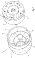
Sur les
Avantageusement, le pulvérisateur 1 est un pulvérisateur électrostatique.Advantageously, the
Le pulvérisateur 1 est globalement à géométrie de révolution autour d'un axe X-X', lequel forme un axe de pulvérisation du produit de revêtement. Le pulvérisateur 1 comprend un corps 3 représenté schématiquement en traits mixtes à la
Dans la présente demande, une direction avant désigne une direction axiale parallèle à l'axe X-X' qui est orientée dans le sens de la pulvérisation, c'est-à-dire vers la gauche à la
Un épaulement 20 diminue le diamètre extérieur du stator 2 de la turbine en allant vers l'avant. Le stator de turbine 2 délimite un alésage central 22 de réception du rotor. L'épaulement 20 du stator 2 délimite une surface annulaire perpendiculaire à l'axe X-X'. Cette surface annulaire comporte au moins un évidement 24, dans lequel est reçu un moyen d'attraction magnétique 6. Dans l'exemple, ce moyen d'attraction magnétique est un aimant permanent.A
Avantageusement, le stator 2 délimite trois évidements 24 qui sont répartis de manière régulière autour de l'axe X-X' et qui reçoivent chacun un aimant 6. La force des aimants 6 est suffisante pour écraser les joints d'étanchéité entre la jupe et le corps et assurer ainsi une bonne étanchéité. Cette force est comprise entre 10kN et 200kN, de préférence de l'ordre de 100 kN à l'arrachement dans le sens axial.Advantageously, the
Dans l'exemple, les aimants 6 sont des portions de bague. Cependant, la forme des aimants 6 n'est pas limitative. Ainsi, les aimants 6 peuvent avoir toute forme adaptée à la géométrie du pulvérisateur, comme une forme à section carrée, rectangulaire, circulaire ou encore elliptique.In the example, the
Le stator 2 comprend au moins un pion qui fait saillie radialement vers l'extérieur par rapport à sa surface extérieure du stator 2. Dans l'exemple, le stator 2 comprend trois pions, parmi lesquels deux pions sont référencés 26a et un pion est référencé 26b. Les deux pions 26a sont les pions qui sont les moins espacés l'un de l'autre. Un seul de ces deux pions 26a est visible à la
Le stator 2 délimite des trous 21, dont deux sont visible à la
Le stator 2 est traversé par des circuits indépendants 28, dont huit sont visibles à la
Un élément 4 de guidage d'air est fixé sur un organe fixe du pulvérisateur 1. Dans l'exemple, cet élément est une jupe et l'organe fixe est le stator 2 de la turbine. Avantageusement, la jupe, comprend une partie intérieure 4a et une partie extérieure 4b vissée autour de la partie intérieure 4a. A titre de variante non représentée, la jupe 4 est monobloc. La jupe 4 est à géométrie de révolution autour de l'axe X-X'. La partie intérieure 4b de la jupe 4 comporte un épaulement 40 complémentaire de l'épaulement 20 du stator 2 de la turbine. Ainsi, les épaulements 20 et 40 sont en contact l'un avec l'autre en configuration montée de la jupe 4. L'épaulement 40 diminue le diamètre intérieur de la jupe 4 dans la direction avant. L'épaulement 40 forme une surface perpendiculaire à l'axe X-X' délimitant au moins un évidement 44 dans lequel est logée une pièce 8 réalisée dans un alliage ferromagnétique non magnétisé. Dans l'exemple, le stator 2 délimite trois évidements 44. Il y a donc autant d'aimants 6 que de pièces en matériau ferromagnétique 8. Ainsi, chaque aimant 6 coopère avec une pièce 8 correspondante pour fixer la jupe 4 au stator 2 de la turbine. Les aimants 6 et les pièces 8 en matériau ferromagnétique forment donc ensemble des moyens de fixation de la jupe 4 sur le stator 2 de la turbine. Le fait de fixer la jupe 4 par aimantation permet de s'affranchir de l'utilisation de pas de vis très fins, qui nécessitent une attention particulière lors du montage et du démontage de la jupe 4 et qui sont sujets aux dégradations.An
La partie intérieure 4b de la jupe 4 dépasse axialement vers l'arrière par rapport à la partie extérieure 4a. Elle comprend donc une portion arrière saillante, qui délimite au moins une encoche. Dans l'exemple, la partie intérieure 4b de la jupe 4 délimite trois encoches, parmi lesquelles deux encoches sont référencées 42a et une encoche est référencée 42b. Il y a donc autant d'encoches que de pions. Les deux encoches 42a sont celles qui sont les moins espacées l'une de l'autre. Les encoches 42a et 42b sont donc réparties de manière irrégulière autour de l'axe X-X'. Les encoches 42a sont respectivement prévues pour guider les pions 26a lors de la fixation de la jupe 4 sur le stator 2, alors que l'encoche 42b est prévue pour guider le pion 26b.The
Chaque encoche 42a et 42b présente avantageusement une longueur comprise entre 10 mm et 50 mm, de préférence de l'ordre de 20 mm.Each
Avantageusement, chaque encoche 42a, 42b est conformée de sorte que la jupe 4 peut tourner autour de l'axe X-X' et par rapport au stator 2 lorsque les pions correspondants 26a, 26b sont déplacés dans les encoches 42a, 42b. Cela procure l'avantage de faciliter le démontage de la jupe 4 car les efforts nécessaires pour éloigner la jupe 4 et le stator 2 l'un de l'autre sont moindres par rapport à une configuration où la jupe serait détachée du stator 2 par un mouvement purement axial.Advantageously, each
Avantageusement, chaque encoche 42a ou 42b s'étend selon une direction hélicoïdale autour de l'axe central X-X', avec un angle d'hélice θ compris entre 5° et 75°, notamment de l'ordre de 60°. Cet angle θ est mesuré par rapport à une direction orthoradiale à l'axe X-X'. Dans l'exemple, le pas de chaque encoche 42a et 42b autour de l'axe X-X' est à droite vu du côté opposé à l'organe fixe 2, c'est-à-dire vu de la gauche aux
Cependant, à titre de variante non représentée, les encoches 42a et 42b s'étendent selon une direction différente. Par exemple, les encoches 42a et 42b peuvent s'étendre parallèlement à l'axe X-X', de manière oblique ou coudée. On peut également envisager un mode de réalisation où les encoches s'étendent, vers l'avant à partir du bord arrière de la jupe 4, d'abord selon une direction axiale, puis selon une direction oblique, hélicoïdale ou encore curviligne.However, as a variant not shown, the
Avantageusement, la portion de la partie 4a de la jupe qui délimite les encoches 42a et 42b présente une épaisseur radiale sensiblement égale à la hauteur des pions 26a et 26b, de sorte que les pions 26a et 26b ne font pas saillie radialement vers l'extérieur en configuration assemblée du pulvérisateur 1. Chaque pion 26a et 26b ne dépasse donc pas radialement par rapport à la surface extérieure de la jupe 4. Les pions 26a et 26b ne génèrent donc pas de turbulences lors du déplacement du robot.Advantageously, the portion of the
La jupe 4 délimite des circuits indépendants, complémentaires des circuits 28 délimités dans le stator 2 ; c'est pourquoi, la position angulaire de la jupe 4 autour de l'axe X-X' par rapport au stator 2 de la turbine est prédéfinie. A défaut, les circuits de la jupe 4 ne seraient pas connectés avec ceux définis dans le stator 2 de la turbine.The
Pour monter manuellement la jupe 4 sur le stator 2 du pulvérisateur 1, il convient de rapprocher axialement les deux éléments l'un de l'autre jusqu'à parvenir dans une position dans laquelle l'élément de guidage d'air 4 est fixé à l'organe fixe 2 par coopération du moyen d'attraction magnétique 6 avec la pièce en matériau ferromagnétique 8.To manually mount the
Plus précisément, la jupe 4 est orientée autour de l'axe X-X' de manière à aligner les pions 26a avec les encoches 42a et le pion 26b avec l'encoche 42b. La position des encoches 42a et 42b forme alors un détrompeur mécanique empêchant l'opérateur de se tromper lorsqu'il assemble la jupe 4 sur le stator 2. Les pions 26a et 26b du stator 2 pénètrent alors dans les encoches correspondantes 42a et 42b de la jupe 4. Les encoches 42a et 42b sont conformées de manière que la jupe tourne automatiquement autour de l'axe X-X' au fur et à mesure que les pions 26a et 26b pénètrent en direction du fond des encoches correspondantes, c'est-à-dire au fur et à mesure que l'on approche la jupe 4 et le stator 2 de la turbine. Les pièces en matériau ferromagnétique 8 sont attirées par les aimants 6 et les pions 26a et 26b parviennent jusqu'au fond des encoches 42a et 42b. La jupe est alors orientée dans la position angulaire prédéfinie, dans laquelle une connexion étanche peut être réalisée entre les circuits respectifs de la jupe 4 et du stator de la turbine 2. Les encoches 42a, 42b et les pions 26a, 26b forment donc des moyens pour orienter automatiquement la jupe autour de l'axe X-X' dans une position angulaire prédéfinie par rapport au stator 2 de la turbine.More specifically, the
La jupe 4 peut aussi être montée de manière automatique en utilisant le mouvement du robot multiaxes. Dans ce cas, la jupe 4 est montée sur un support sur lequel elle est immobilisée en rotation autour de son axe X-X', mais libre en translation suivant son axe X-X'. En variante, la jupe 4 peut être bloquée aussi en translation. Un exemple de support est une colonne, à l'intérieur de laquelle est reçue la jupe 4. Pour assurer le montage de la jupe 4, le robot multiaxes amène l'organe fixe 2 dans une configuration dans laquelle chaque pion 26a et 26b est face à une encoche 42a et 42b correspondante et effectue un mouvement de rotation autour de l'axe central X-X' pour engager chacun des pions 26a et 26b à l'intérieur de l'encoche correspondante. Plus précisément, le déplacement relatif entre l'élément de guidage 4 et l'organe fixe 2 est un déplacement à la fois en translation suivant l'axe central X-X' et en rotation autour de l'axe central X-X'.The
Pour démonter manuellement la jupe 4 du stator 2 de la turbine, il convient d'orienter l'élément de guidage d'air 4 et l'organe fixe 2 l'un par rapport à l'autre autour de l'axe central X-X' jusqu'à parvenir dans une position dans laquelle le moyen d'attraction magnétique 6 ne coopère plus avec la pièce en matériau ferromagnétique 8.To manually remove the
Plus précisément, la jupe 4 est pivotée autour de l'axe X-X' afin de déplacer les pions 22a et 22b selon une direction opposée au fond des encoches 42a et 42b. Cela permet de désaxer les pièces 8 en matériau ferromagnétique et les aimants 6 : les aimants 6 ne sont plus radialement en regard des pièces 8. La force d'attraction magnétique entre les aimants 6 et les pièces en matériau ferromagnétique 8 est ainsi réduite.Specifically, the
Cette opération peut aussi être effectuée de manière automatisée, comme détaillé ci-après.This operation can also be performed automatically, as detailed below.
Le robot multiaxes amène le pulvérisateur 1, alors monté à l'extrémité du bras du robot, sur un support configuré pour empêcher la rotation de la jupe 4 autour de son axe X-X'. Sur le support, la jupe 4 reste toutefois libre en translation suivant l'axe X-X'. En variante, la jupe 4 est également immobilisée sur le support en translation suivant l'axe X-X'. Une fois que la jupe 4 est immobilisée en rotation, le robot effectue un mouvement de rotation autour de l'axe central X-X' pour dégager chacun des pions 26a et 26b à l'extérieur l'encoche correspondante. Plus précisément, le déplacement relatif entre l'élément de guidage 4 immobilisé sur le support et l'organe fixe 2 monté à l'extrémité du bras du robot est un déplacement à la fois en translation suivant l'axe central X-X' et en rotation autour de l'axe central X-X'. Les éléments 6 et 8 ne sont alors plus en face les uns par rapport aux autres et il n'y a plus d'attraction magnétique et la jupe 4 peut être nettoyée ou remplacée.The multiaxis robot brings the
Sur la
Dans ce mode de réalisation, la jupe 4' délimite une ou plusieurs encoches 42' qui s'étendent chacune parallèlement à l'axe central X-X'.In this embodiment, the skirt 4 'delimits one or more notches 42' which each extend parallel to the central axis X-X '.
Le montage manuel de la jupe 4' sur l'organe fixe s'effectue alors simplement en orientant la jupe 4' dans une configuration où chaque encoche 42' est face à un pion correspondant 26' et à rapprocher axialement la jupe 4 et l'organe fixe. Cette opération peut aussi être effectuée par le robot multiaxes lui-même, auquel cas le robot oriente automatiquement l'organe fixe dans la configuration précitée. Une fois cette configuration atteinte, la jupe 4 se déplace automatiquement, suivant un mouvement de translation, en direction de l'organe fixe sous l'effet de l'attraction magnétique.The manual assembly of the skirt 4 'on the fixed member is then performed simply by orienting the skirt 4' in a configuration where each notch 42 'is facing a corresponding pin 26' and axially bring the
Pour démonter la jupe 4, on utilise un outil spécifique, notamment une pince, comprenant deux mords 100A et 100B. Chacun des mords 100A et 100B comprend au moins un biseau 102, notamment deux biseaux 102 et 104, destinés à coopérer avec des surfaces inclinées, respectivement de la jupe 4' et du corps 3 du pulvérisateur 1. En effet, les mords 100A et 100B sont positionnés de manière diamétralement opposée autour du pulvérisateur 1 et sont déplacés radialement l'un en direction de l'autre dans un espace entre la jupe 4 et le corps 3 du pulvérisateur 1, comme représenté par les flèches F1 à la
L'outil peut être manipulé par un opérateur ou un automate.The tool can be manipulated by an operator or a PLC.
En variante non représentée applicable à tous les modes de réalisation, la jupe 4 est fixée directement sur le corps 3 du pulvérisateur, par des moyens de fixation comparables à ceux décrits ci-dessus. Dans ce cas, la turbine ne comporte pas de circuits indépendants 28. L'air comprimé circule alors, par exemple, dans des canaux ménagés entre la jupe 4 et le stator 2 de la turbine.In variant not shown applicable to all embodiments, the
Selon une autre variante non représentée, chaque aimant 6 est porté par la jupe 4, alors que chaque pièce en matériau ferromagnétique 8 est portée par le stator de la turbine 2 ou par le corps du pulvérisateur 3, selon le mode de réalisation considéré.According to another variant not shown, each
Selon une autre variante non représentée, la jupe 4 ou le stator 2 sont en matériau ferromagnétique, notamment dans un alliage ferromagnétique non magnétisé.According to another variant not shown, the
Selon une autre variante non représentée, le ou les pions 26a, 26b appartiennent à la jupe 4 et font saillie radialement vers l'intérieur. Dans ce cas, des rainures sont délimitées sur la surface radiale externe du stator 2 ou sur la surface radiale externe du corps 3 du pulvérisateur 1 de la turbine selon le mode de réalisation considéré. On parle de rampes de positionnement. Les rainures peuvent s'étendre selon n'importe quelle direction, en particulier selon les directions décrites ci-dessus en relation avec les encoches 42a et 42b. Dans le cas de rainures hélicoïdales, ces rainures ont chacune un pas à gauche ou un pas à droite autour de l'axe X-X'.According to another variant not shown, the or pins 26a, 26b belong to the
Selon une autre variante non représentée, une bague est montée de manière mobile en rotation autour de la partie à diamètre rétréci du stator 2 de la turbine. Avantageusement, cette bague comporte plusieurs aimants distribués avec des polarités alternées selon une direction périphérique autour de l'axe central de la bague. La bague n'exerce donc pas le même effet magnétique quelle que soit sa position angulaire. En effet, selon la position angulaire de la bague, celle-ci peut soit attirer des éléments ferromagnétiques, soit les repousser. En configuration montée de la jupe 4 sur le corps 2, il suffit alors de pivoter la bague autour du corps 2 pour repousser la jupe 4 du corps 2, ce qui facilite le démontage de la jupe 4.According to another variant not shown, a ring is rotatably mounted around the narrowed diameter portion of the
Selon une autre variante non représentée, la jupe 4 comprend un logement extérieur, par exemple sous la forme d'un trou borgne, pour recevoir l'ergot d'une clé à ergot. Cette clé à ergot permet alors d'entrainer la jupe 4 en rotation de l'axe central X-X' jusqu'à parvenir dans une position dans laquelle le moyen d'attraction magnétique 6 ne coopère plus avec la pièce en matériau ferromagnétique 8. Cette clé comprend un manche qui se prolonge par un crochet semi-circulaire portant l'ergot et adapté au diamètre extérieur de la jupe 4.According to another variant not shown, the
Selon une autre variante, le démontage de la jupe 4 peut s'effectuer au moyen d'une clé à sangle.According to another variant, the disassembly of the
Selon une autre variante non représentée, le moyen d'attraction magnétique est un électroaimant. Dans ce cas, le démontage de la jupe 4 est facilité car l'électroaimant peut être désactivé en coupant son courant d'alimentation.According to another variant not shown, the magnetic attraction means is an electromagnet. In this case, the disassembly of the
Les caractéristiques techniques du mode de réalisation et des variantes envisagés ci-dessus peuvent être combinées entre elles pour générer de nouveaux modes de réalisation de l'invention.The technical features of the embodiment and the variants envisaged above can be combined with each other to generate new embodiments of the invention.
Claims (15)
Priority Applications (1)
| Application Number | Priority Date | Filing Date | Title |
|---|---|---|---|
| PL17161725T PL3222360T3 (en) | 2016-03-21 | 2017-03-20 | Coating sprayer, method for assembling and disassembling |
Applications Claiming Priority (1)
| Application Number | Priority Date | Filing Date | Title |
|---|---|---|---|
| FR1652390A FR3048896B1 (en) | 2016-03-21 | 2016-03-21 | COATING SPRAYER, METHOD OF MOUNTING AND DISASSEMBLING |
Publications (2)
| Publication Number | Publication Date |
|---|---|
| EP3222360A1 true EP3222360A1 (en) | 2017-09-27 |
| EP3222360B1 EP3222360B1 (en) | 2019-01-02 |
Family
ID=56069109
Family Applications (1)
| Application Number | Title | Priority Date | Filing Date |
|---|---|---|---|
| EP17161725.1A Active EP3222360B1 (en) | 2016-03-21 | 2017-03-20 | Coating sprayer, method for assembling and disassembling |
Country Status (13)
| Country | Link |
|---|---|
| US (1) | US11534777B2 (en) |
| EP (1) | EP3222360B1 (en) |
| JP (1) | JP6974016B2 (en) |
| KR (1) | KR102385123B1 (en) |
| CN (1) | CN107214028A (en) |
| BR (1) | BR102017004740A2 (en) |
| DK (1) | DK3222360T3 (en) |
| ES (1) | ES2712927T3 (en) |
| FR (1) | FR3048896B1 (en) |
| PL (1) | PL3222360T3 (en) |
| PT (1) | PT3222360T (en) |
| RU (1) | RU2725431C2 (en) |
| TR (1) | TR201904233T4 (en) |
Cited By (1)
| Publication number | Priority date | Publication date | Assignee | Title |
|---|---|---|---|---|
| FR3127535A1 (en) * | 2021-09-29 | 2023-03-31 | Exel Industries | Sprayer fixing device on a robotic arm |
Families Citing this family (2)
| Publication number | Priority date | Publication date | Assignee | Title |
|---|---|---|---|---|
| FR3083722B1 (en) * | 2018-07-13 | 2020-10-09 | Exel Ind | TURBINE FOR FLUID SPRAYING DEVICE, FLUID SPRAYING DEVICE, AS WELL AS A SET INCLUDING SUCH A DEVICE AND A TOOL |
| WO2022061306A1 (en) * | 2020-09-21 | 2022-03-24 | Scale Up The Fun LLC | Fluid spray gun |
Citations (4)
| Publication number | Priority date | Publication date | Assignee | Title |
|---|---|---|---|---|
| US20030234299A1 (en) | 2001-08-09 | 2003-12-25 | Toshio Hosoda | Cartridge type coater |
| DE102004032045A1 (en) * | 2004-07-02 | 2006-01-26 | J. Wagner Ag | Rotary atomizer for atomizing liquid and powdered media, especially paints, lacquers and similar materials comprises a housing and a bell having regions made from plastic or aluminum |
| US20150258554A1 (en) * | 2014-03-14 | 2015-09-17 | Gunnar van der Steur | Rotary atomizer edge guard |
| WO2015191323A1 (en) | 2014-06-10 | 2015-12-17 | 3M Innovative Properties Company | Nozzle assembly with external baffles |
Family Cites Families (21)
| Publication number | Priority date | Publication date | Assignee | Title |
|---|---|---|---|---|
| JPS5872299A (en) | 1981-10-23 | 1983-04-30 | 株式会社山武 | Damping circuit |
| SU1214228A1 (en) | 1984-08-08 | 1986-02-28 | Всесоюзный Научно-Исследовательский Биотехнический Институт | Centrifugal liquid sprayer |
| AU4141889A (en) | 1988-10-20 | 1990-04-26 | Nordson Corporation | Powder or solid particulate material spray gun |
| US5078321A (en) | 1990-06-22 | 1992-01-07 | Nordson Corporation | Rotary atomizer cup |
| SE507891C2 (en) | 1992-04-23 | 1998-07-27 | Fischer Ag E | Spray Nozzle |
| DE69827476T2 (en) * | 1998-01-13 | 2005-10-27 | Abb K.K. | COATING DEVICE WITH A TURNING SPRAY HEAD |
| FR2805182B1 (en) * | 2000-02-21 | 2002-09-20 | Sames Sa | COATING PRODUCT SPRAYING DEVICE COMPRISING A ROTATING SPRAYING ELEMENT |
| FR2812567B1 (en) | 2000-08-07 | 2003-03-07 | Sames Sa | COATING PROJECTION DEVICE COMPRISING A NOZZLE |
| WO2004024338A2 (en) | 2002-09-13 | 2004-03-25 | Sames Technologies | Spray bowl, discharge device comprising one such bowl and discharge installation comprising one such device |
| ATE390207T1 (en) * | 2004-02-06 | 2008-04-15 | Sames Technologies | SPRAY BELL FOR A ROTARY ATOMIZER WITH MAGNETIC MOUNTING |
| FR2874518B1 (en) | 2004-08-25 | 2006-12-22 | Sames Technologies Soc Par Act | ROTATING PROJECTOR OF COATING PRODUCT, INSTALLATION COMPRISING SUCH A PROJECTOR AND METHOD OF VERIFYING THE OPERATION OF SUCH A PROJECTOR |
| US7654472B2 (en) * | 2005-10-21 | 2010-02-02 | Durr Systems, Inc. | Rotary atomizer with a spraying body |
| GB0625583D0 (en) | 2006-12-21 | 2007-01-31 | Itw Ltd | Paint spray apparatus |
| JP5183163B2 (en) | 2007-11-16 | 2013-04-17 | 旭サナック株式会社 | Rotating atomizing head |
| DE102009013979A1 (en) | 2009-03-19 | 2010-09-23 | Dürr Systems GmbH | Electrode arrangement for an electrostatic atomizer |
| FR2945461B1 (en) | 2009-05-13 | 2012-10-05 | Sames Technologies | PROJECTOR AND SPRAYING DEVICE OF COATING PRODUCT AND PROJECTION METHOD COMPRISING SUCH A PROJECTOR |
| RU101944U1 (en) | 2010-10-14 | 2011-02-10 | Владимир Михайлович Тарасов | SPRAY DEVICE |
| US8608502B2 (en) * | 2012-05-08 | 2013-12-17 | Otter Products, Llc | Connection mechanism |
| DE102013223688A1 (en) * | 2013-11-20 | 2015-05-21 | Siemens Aktiengesellschaft | Method and device for the automated application of a spray coating |
| JP6789987B2 (en) | 2015-05-27 | 2020-11-25 | スリーエム イノベイティブ プロパティズ カンパニー | Sprayer with auxiliary opening |
| JP7036681B2 (en) | 2018-06-25 | 2022-03-15 | 大同プラント工業株式会社 | Heat treatment furnace |
-
2016
- 2016-03-21 FR FR1652390A patent/FR3048896B1/en not_active Expired - Fee Related
-
2017
- 2017-03-01 US US15/446,383 patent/US11534777B2/en active Active
- 2017-03-09 BR BR102017004740-7A patent/BR102017004740A2/en not_active Application Discontinuation
- 2017-03-16 JP JP2017051168A patent/JP6974016B2/en active Active
- 2017-03-20 EP EP17161725.1A patent/EP3222360B1/en active Active
- 2017-03-20 CN CN201710164312.XA patent/CN107214028A/en active Pending
- 2017-03-20 KR KR1020170034894A patent/KR102385123B1/en active IP Right Grant
- 2017-03-20 DK DK17161725.1T patent/DK3222360T3/en active
- 2017-03-20 TR TR2019/04233T patent/TR201904233T4/en unknown
- 2017-03-20 ES ES17161725T patent/ES2712927T3/en active Active
- 2017-03-20 PT PT17161725T patent/PT3222360T/en unknown
- 2017-03-20 RU RU2017109085A patent/RU2725431C2/en active
- 2017-03-20 PL PL17161725T patent/PL3222360T3/en unknown
Patent Citations (4)
| Publication number | Priority date | Publication date | Assignee | Title |
|---|---|---|---|---|
| US20030234299A1 (en) | 2001-08-09 | 2003-12-25 | Toshio Hosoda | Cartridge type coater |
| DE102004032045A1 (en) * | 2004-07-02 | 2006-01-26 | J. Wagner Ag | Rotary atomizer for atomizing liquid and powdered media, especially paints, lacquers and similar materials comprises a housing and a bell having regions made from plastic or aluminum |
| US20150258554A1 (en) * | 2014-03-14 | 2015-09-17 | Gunnar van der Steur | Rotary atomizer edge guard |
| WO2015191323A1 (en) | 2014-06-10 | 2015-12-17 | 3M Innovative Properties Company | Nozzle assembly with external baffles |
Cited By (2)
| Publication number | Priority date | Publication date | Assignee | Title |
|---|---|---|---|---|
| FR3127535A1 (en) * | 2021-09-29 | 2023-03-31 | Exel Industries | Sprayer fixing device on a robotic arm |
| EP4159321A1 (en) | 2021-09-29 | 2023-04-05 | Exel Industries | Device for attaching a sprayer to a robot arm |
Also Published As
| Publication number | Publication date |
|---|---|
| US11534777B2 (en) | 2022-12-27 |
| ES2712927T3 (en) | 2019-05-16 |
| RU2017109085A3 (en) | 2020-05-22 |
| US20170266672A1 (en) | 2017-09-21 |
| EP3222360B1 (en) | 2019-01-02 |
| JP6974016B2 (en) | 2021-12-01 |
| PL3222360T3 (en) | 2019-06-28 |
| KR20170109500A (en) | 2017-09-29 |
| FR3048896A1 (en) | 2017-09-22 |
| DK3222360T3 (en) | 2019-02-25 |
| FR3048896B1 (en) | 2018-04-13 |
| KR102385123B1 (en) | 2022-04-11 |
| RU2725431C2 (en) | 2020-07-02 |
| CN107214028A (en) | 2017-09-29 |
| BR102017004740A2 (en) | 2017-12-12 |
| TR201904233T4 (en) | 2019-05-21 |
| RU2017109085A (en) | 2018-09-20 |
| JP2017170436A (en) | 2017-09-28 |
| PT3222360T (en) | 2019-04-29 |
Similar Documents
| Publication | Publication Date | Title |
|---|---|---|
| EP3222360B1 (en) | Coating sprayer, method for assembling and disassembling | |
| CA2399624C (en) | Device for spraying a coating product and spraying rotary element for same | |
| JP6889654B2 (en) | Work rotation device and painting method using it | |
| EP1711269B1 (en) | Spray bowl for a rotary projector with magnetic attachment | |
| EP0053543B1 (en) | Devices for fixing objects to sheet metals accessible from one side only | |
| EP2496849B1 (en) | Self-locking screwing attachment device and assembly provided with same | |
| CA2607875A1 (en) | Idler pulley or roller device | |
| FR2698564A1 (en) | Apparatus for spraying spray coating product and tool for mounting and dismounting such a rotating element. | |
| FR3035928A1 (en) | PULLEY DEVICE FOR TILT ROLLER OR ROLLER | |
| EP2429716A1 (en) | Projector and member for spraying a coating material, and spraying method using such a sprayer | |
| FR3037115A1 (en) | PULLEY DEVICE FOR TILT ROLLER OR ROLLER | |
| FR2863188A1 (en) | MANDREL | |
| FR3103718A1 (en) | Rotating electrostatic projector for coating product and projection installation comprising such a projector | |
| FR3029457A1 (en) | ASSEMBLY COMPRISING A RIM AND A SHAFT EQUIPPED WITH AN AXIAL LOCK HUB | |
| EP2142307A1 (en) | Spraying member, spraying device comprising such a member and spraying installation comprising such a device | |
| EP4159321B1 (en) | Device for attaching a sprayer to a robot arm | |
| FR3010460A1 (en) | PELTON TURBINE HYDRAULIC INJECTOR AND METHOD FOR PARTIALLY DISASSEMBLING SUCH INJECTOR | |
| WO2022184785A1 (en) | Stop system for a tool for heating by direct contact | |
| FR2852368A1 (en) | BEARING IMMOBILIZED IN A HOUSING BY MEANS OF A REVERSIBLE MOVABLE MEMBER | |
| FR2793729A1 (en) | COVER DEVICE WITH ADVERTISING SCREEN MOUNTED ON A RIM OF A VEHICLE WHEEL | |
| FR2894310A1 (en) | Freewheel hub for two wheeler wheel, has central shaft and holding unit with ring independent from pawl whereby ring is provided on base of holding unit | |
| WO1995000250A1 (en) | Electrostatic spraying device with rotary spray head, for spraying a coating product in powder form | |
| EP1713617A1 (en) | Supporting assembly and rotary working member, particularly an abrasive disc, releasably mountable on a drive shaft | |
| FR2943306A1 (en) | System for mounting lighting device in housing of motor vehicle, has fixation module allowing removable assembling of lighting device in housing, where fixation module is integrated to housing when lighting device is withdrawn |
Legal Events
| Date | Code | Title | Description |
|---|---|---|---|
| PUAI | Public reference made under article 153(3) epc to a published international application that has entered the european phase |
Free format text: ORIGINAL CODE: 0009012 |
|
| STAA | Information on the status of an ep patent application or granted ep patent |
Free format text: STATUS: THE APPLICATION HAS BEEN PUBLISHED |
|
| AK | Designated contracting states |
Kind code of ref document: A1 Designated state(s): AL AT BE BG CH CY CZ DE DK EE ES FI FR GB GR HR HU IE IS IT LI LT LU LV MC MK MT NL NO PL PT RO RS SE SI SK SM TR |
|
| AX | Request for extension of the european patent |
Extension state: BA ME |
|
| STAA | Information on the status of an ep patent application or granted ep patent |
Free format text: STATUS: REQUEST FOR EXAMINATION WAS MADE |
|
| 17P | Request for examination filed |
Effective date: 20180305 |
|
| RBV | Designated contracting states (corrected) |
Designated state(s): AL AT BE BG CH CY CZ DE DK EE ES FI FR GB GR HR HU IE IS IT LI LT LU LV MC MK MT NL NO PL PT RO RS SE SI SK SM TR |
|
| GRAP | Despatch of communication of intention to grant a patent |
Free format text: ORIGINAL CODE: EPIDOSNIGR1 |
|
| STAA | Information on the status of an ep patent application or granted ep patent |
Free format text: STATUS: GRANT OF PATENT IS INTENDED |
|
| INTG | Intention to grant announced |
Effective date: 20180802 |
|
| GRAS | Grant fee paid |
Free format text: ORIGINAL CODE: EPIDOSNIGR3 |
|
| GRAA | (expected) grant |
Free format text: ORIGINAL CODE: 0009210 |
|
| STAA | Information on the status of an ep patent application or granted ep patent |
Free format text: STATUS: THE PATENT HAS BEEN GRANTED |
|
| AK | Designated contracting states |
Kind code of ref document: B1 Designated state(s): AL AT BE BG CH CY CZ DE DK EE ES FI FR GB GR HR HU IE IS IT LI LT LU LV MC MK MT NL NO PL PT RO RS SE SI SK SM TR |
|
| REG | Reference to a national code |
Ref country code: GB Ref legal event code: FG4D Free format text: NOT ENGLISH |
|
| REG | Reference to a national code |
Ref country code: CH Ref legal event code: EP Ref country code: AT Ref legal event code: REF Ref document number: 1083695 Country of ref document: AT Kind code of ref document: T Effective date: 20190115 |
|
| REG | Reference to a national code |
Ref country code: IE Ref legal event code: FG4D Free format text: LANGUAGE OF EP DOCUMENT: FRENCH |
|
| REG | Reference to a national code |
Ref country code: DE Ref legal event code: R096 Ref document number: 602017001621 Country of ref document: DE |
|
| REG | Reference to a national code |
Ref country code: CH Ref legal event code: NV Representative=s name: MICHELI AND CIE SA, CH |
|
| REG | Reference to a national code |
Ref country code: DK Ref legal event code: T3 Effective date: 20190218 |
|
| REG | Reference to a national code |
Ref country code: NL Ref legal event code: FP |
|
| REG | Reference to a national code |
Ref country code: RO Ref legal event code: EPE |
|
| REG | Reference to a national code |
Ref country code: SE Ref legal event code: TRGR |
|
| REG | Reference to a national code |
Ref country code: PT Ref legal event code: SC4A Ref document number: 3222360 Country of ref document: PT Date of ref document: 20190429 Kind code of ref document: T Free format text: AVAILABILITY OF NATIONAL TRANSLATION Effective date: 20190402 |
|
| REG | Reference to a national code |
Ref country code: ES Ref legal event code: FG2A Ref document number: 2712927 Country of ref document: ES Kind code of ref document: T3 Effective date: 20190516 |
|
| REG | Reference to a national code |
Ref country code: LT Ref legal event code: MG4D |
|
| REG | Reference to a national code |
Ref country code: AT Ref legal event code: MK05 Ref document number: 1083695 Country of ref document: AT Kind code of ref document: T Effective date: 20190102 |
|
| PG25 | Lapsed in a contracting state [announced via postgrant information from national office to epo] |
Ref country code: FI Free format text: LAPSE BECAUSE OF FAILURE TO SUBMIT A TRANSLATION OF THE DESCRIPTION OR TO PAY THE FEE WITHIN THE PRESCRIBED TIME-LIMIT Effective date: 20190102 Ref country code: LT Free format text: LAPSE BECAUSE OF FAILURE TO SUBMIT A TRANSLATION OF THE DESCRIPTION OR TO PAY THE FEE WITHIN THE PRESCRIBED TIME-LIMIT Effective date: 20190102 Ref country code: NO Free format text: LAPSE BECAUSE OF FAILURE TO SUBMIT A TRANSLATION OF THE DESCRIPTION OR TO PAY THE FEE WITHIN THE PRESCRIBED TIME-LIMIT Effective date: 20190402 |
|
| PG25 | Lapsed in a contracting state [announced via postgrant information from national office to epo] |
Ref country code: GR Free format text: LAPSE BECAUSE OF FAILURE TO SUBMIT A TRANSLATION OF THE DESCRIPTION OR TO PAY THE FEE WITHIN THE PRESCRIBED TIME-LIMIT Effective date: 20190403 Ref country code: HR Free format text: LAPSE BECAUSE OF FAILURE TO SUBMIT A TRANSLATION OF THE DESCRIPTION OR TO PAY THE FEE WITHIN THE PRESCRIBED TIME-LIMIT Effective date: 20190102 Ref country code: LV Free format text: LAPSE BECAUSE OF FAILURE TO SUBMIT A TRANSLATION OF THE DESCRIPTION OR TO PAY THE FEE WITHIN THE PRESCRIBED TIME-LIMIT Effective date: 20190102 Ref country code: IS Free format text: LAPSE BECAUSE OF FAILURE TO SUBMIT A TRANSLATION OF THE DESCRIPTION OR TO PAY THE FEE WITHIN THE PRESCRIBED TIME-LIMIT Effective date: 20190502 Ref country code: BG Free format text: LAPSE BECAUSE OF FAILURE TO SUBMIT A TRANSLATION OF THE DESCRIPTION OR TO PAY THE FEE WITHIN THE PRESCRIBED TIME-LIMIT Effective date: 20190402 Ref country code: RS Free format text: LAPSE BECAUSE OF FAILURE TO SUBMIT A TRANSLATION OF THE DESCRIPTION OR TO PAY THE FEE WITHIN THE PRESCRIBED TIME-LIMIT Effective date: 20190102 |
|
| REG | Reference to a national code |
Ref country code: DE Ref legal event code: R097 Ref document number: 602017001621 Country of ref document: DE |
|
| PG25 | Lapsed in a contracting state [announced via postgrant information from national office to epo] |
Ref country code: AT Free format text: LAPSE BECAUSE OF FAILURE TO SUBMIT A TRANSLATION OF THE DESCRIPTION OR TO PAY THE FEE WITHIN THE PRESCRIBED TIME-LIMIT Effective date: 20190102 Ref country code: EE Free format text: LAPSE BECAUSE OF FAILURE TO SUBMIT A TRANSLATION OF THE DESCRIPTION OR TO PAY THE FEE WITHIN THE PRESCRIBED TIME-LIMIT Effective date: 20190102 Ref country code: AL Free format text: LAPSE BECAUSE OF FAILURE TO SUBMIT A TRANSLATION OF THE DESCRIPTION OR TO PAY THE FEE WITHIN THE PRESCRIBED TIME-LIMIT Effective date: 20190102 Ref country code: MC Free format text: LAPSE BECAUSE OF FAILURE TO SUBMIT A TRANSLATION OF THE DESCRIPTION OR TO PAY THE FEE WITHIN THE PRESCRIBED TIME-LIMIT Effective date: 20190102 |
|
| PLBE | No opposition filed within time limit |
Free format text: ORIGINAL CODE: 0009261 |
|
| STAA | Information on the status of an ep patent application or granted ep patent |
Free format text: STATUS: NO OPPOSITION FILED WITHIN TIME LIMIT |
|
| PG25 | Lapsed in a contracting state [announced via postgrant information from national office to epo] |
Ref country code: LU Free format text: LAPSE BECAUSE OF NON-PAYMENT OF DUE FEES Effective date: 20190320 Ref country code: SM Free format text: LAPSE BECAUSE OF FAILURE TO SUBMIT A TRANSLATION OF THE DESCRIPTION OR TO PAY THE FEE WITHIN THE PRESCRIBED TIME-LIMIT Effective date: 20190102 |
|
| 26N | No opposition filed |
Effective date: 20191003 |
|
| REG | Reference to a national code |
Ref country code: BE Ref legal event code: MM Effective date: 20190331 |
|
| PG25 | Lapsed in a contracting state [announced via postgrant information from national office to epo] |
Ref country code: IE Free format text: LAPSE BECAUSE OF NON-PAYMENT OF DUE FEES Effective date: 20190320 |
|
| PG25 | Lapsed in a contracting state [announced via postgrant information from national office to epo] |
Ref country code: SI Free format text: LAPSE BECAUSE OF FAILURE TO SUBMIT A TRANSLATION OF THE DESCRIPTION OR TO PAY THE FEE WITHIN THE PRESCRIBED TIME-LIMIT Effective date: 20190102 Ref country code: BE Free format text: LAPSE BECAUSE OF NON-PAYMENT OF DUE FEES Effective date: 20190331 |
|
| PGFP | Annual fee paid to national office [announced via postgrant information from national office to epo] |
Ref country code: SE Payment date: 20200327 Year of fee payment: 4 Ref country code: DK Payment date: 20200227 Year of fee payment: 4 Ref country code: RO Payment date: 20200225 Year of fee payment: 4 Ref country code: PL Payment date: 20200217 Year of fee payment: 4 Ref country code: NL Payment date: 20200227 Year of fee payment: 4 Ref country code: PT Payment date: 20200217 Year of fee payment: 4 |
|
| PGFP | Annual fee paid to national office [announced via postgrant information from national office to epo] |
Ref country code: CZ Payment date: 20200219 Year of fee payment: 4 Ref country code: SK Payment date: 20200218 Year of fee payment: 4 |
|
| PG25 | Lapsed in a contracting state [announced via postgrant information from national office to epo] |
Ref country code: MT Free format text: LAPSE BECAUSE OF FAILURE TO SUBMIT A TRANSLATION OF THE DESCRIPTION OR TO PAY THE FEE WITHIN THE PRESCRIBED TIME-LIMIT Effective date: 20190102 |
|
| PG25 | Lapsed in a contracting state [announced via postgrant information from national office to epo] |
Ref country code: CY Free format text: LAPSE BECAUSE OF FAILURE TO SUBMIT A TRANSLATION OF THE DESCRIPTION OR TO PAY THE FEE WITHIN THE PRESCRIBED TIME-LIMIT Effective date: 20190102 |
|
| PG25 | Lapsed in a contracting state [announced via postgrant information from national office to epo] |
Ref country code: HU Free format text: LAPSE BECAUSE OF FAILURE TO SUBMIT A TRANSLATION OF THE DESCRIPTION OR TO PAY THE FEE WITHIN THE PRESCRIBED TIME-LIMIT; INVALID AB INITIO Effective date: 20170320 |
|
| PG25 | Lapsed in a contracting state [announced via postgrant information from national office to epo] |
Ref country code: CZ Free format text: LAPSE BECAUSE OF NON-PAYMENT OF DUE FEES Effective date: 20210320 |
|
| REG | Reference to a national code |
Ref country code: DK Ref legal event code: EBP Effective date: 20210331 |
|
| REG | Reference to a national code |
Ref country code: NL Ref legal event code: MM Effective date: 20210401 |
|
| REG | Reference to a national code |
Ref country code: SK Ref legal event code: MM4A Ref document number: E 30514 Country of ref document: SK Effective date: 20210320 |
|
| PG25 | Lapsed in a contracting state [announced via postgrant information from national office to epo] |
Ref country code: RO Free format text: LAPSE BECAUSE OF NON-PAYMENT OF DUE FEES Effective date: 20210320 Ref country code: PT Free format text: LAPSE BECAUSE OF NON-PAYMENT OF DUE FEES Effective date: 20210920 |
|
| PG25 | Lapsed in a contracting state [announced via postgrant information from national office to epo] |
Ref country code: SK Free format text: LAPSE BECAUSE OF NON-PAYMENT OF DUE FEES Effective date: 20210320 Ref country code: SE Free format text: LAPSE BECAUSE OF NON-PAYMENT OF DUE FEES Effective date: 20210321 Ref country code: NL Free format text: LAPSE BECAUSE OF NON-PAYMENT OF DUE FEES Effective date: 20210401 |
|
| PG25 | Lapsed in a contracting state [announced via postgrant information from national office to epo] |
Ref country code: DK Free format text: LAPSE BECAUSE OF NON-PAYMENT OF DUE FEES Effective date: 20210331 |
|
| PG25 | Lapsed in a contracting state [announced via postgrant information from national office to epo] |
Ref country code: MK Free format text: LAPSE BECAUSE OF FAILURE TO SUBMIT A TRANSLATION OF THE DESCRIPTION OR TO PAY THE FEE WITHIN THE PRESCRIBED TIME-LIMIT Effective date: 20190102 |
|
| PGFP | Annual fee paid to national office [announced via postgrant information from national office to epo] |
Ref country code: FR Payment date: 20230320 Year of fee payment: 7 |
|
| PG25 | Lapsed in a contracting state [announced via postgrant information from national office to epo] |
Ref country code: PL Free format text: LAPSE BECAUSE OF NON-PAYMENT OF DUE FEES Effective date: 20210320 |
|
| PGFP | Annual fee paid to national office [announced via postgrant information from national office to epo] |
Ref country code: TR Payment date: 20230313 Year of fee payment: 7 Ref country code: IT Payment date: 20230308 Year of fee payment: 7 Ref country code: GB Payment date: 20230324 Year of fee payment: 7 Ref country code: DE Payment date: 20230307 Year of fee payment: 7 |
|
| PGFP | Annual fee paid to national office [announced via postgrant information from national office to epo] |
Ref country code: ES Payment date: 20230405 Year of fee payment: 7 Ref country code: CH Payment date: 20230402 Year of fee payment: 7 |