EP3220994B1 - Système de cathéter à ballonnet - Google Patents
Système de cathéter à ballonnet Download PDFInfo
- Publication number
- EP3220994B1 EP3220994B1 EP15798252.1A EP15798252A EP3220994B1 EP 3220994 B1 EP3220994 B1 EP 3220994B1 EP 15798252 A EP15798252 A EP 15798252A EP 3220994 B1 EP3220994 B1 EP 3220994B1
- Authority
- EP
- European Patent Office
- Prior art keywords
- balloon
- fibers
- grid
- regions
- inflated
- Prior art date
- Legal status (The legal status is an assumption and is not a legal conclusion. Google has not performed a legal analysis and makes no representation as to the accuracy of the status listed.)
- Active
Links
- 239000000835 fiber Substances 0.000 claims description 120
- 239000000463 material Substances 0.000 claims description 39
- 229940079593 drug Drugs 0.000 claims description 8
- 239000003814 drug Substances 0.000 claims description 8
- 229920000642 polymer Polymers 0.000 claims description 8
- 230000000916 dilatatory effect Effects 0.000 claims description 7
- 239000000203 mixture Substances 0.000 claims description 6
- 239000004699 Ultra-high molecular weight polyethylene Substances 0.000 claims description 5
- -1 polypropylene Polymers 0.000 claims description 5
- 229920000785 ultra high molecular weight polyethylene Polymers 0.000 claims description 5
- 230000001028 anti-proliverative effect Effects 0.000 claims description 3
- 229920000271 Kevlar® Polymers 0.000 claims description 2
- JVTAAEKCZFNVCJ-REOHCLBHSA-N L-lactic acid Chemical compound C[C@H](O)C(O)=O JVTAAEKCZFNVCJ-REOHCLBHSA-N 0.000 claims description 2
- 239000004696 Poly ether ether ketone Substances 0.000 claims description 2
- 239000004743 Polypropylene Substances 0.000 claims description 2
- JUPQTSLXMOCDHR-UHFFFAOYSA-N benzene-1,4-diol;bis(4-fluorophenyl)methanone Chemical compound OC1=CC=C(O)C=C1.C1=CC(F)=CC=C1C(=O)C1=CC=C(F)C=C1 JUPQTSLXMOCDHR-UHFFFAOYSA-N 0.000 claims description 2
- 238000009472 formulation Methods 0.000 claims description 2
- 229920001432 poly(L-lactide) Polymers 0.000 claims description 2
- 229920002530 polyetherether ketone Polymers 0.000 claims description 2
- 229920001155 polypropylene Polymers 0.000 claims description 2
- 239000004761 kevlar Substances 0.000 claims 1
- 239000010410 layer Substances 0.000 description 19
- 238000002399 angioplasty Methods 0.000 description 14
- 238000000034 method Methods 0.000 description 13
- 239000000853 adhesive Substances 0.000 description 8
- 230000001070 adhesive effect Effects 0.000 description 8
- 210000001367 artery Anatomy 0.000 description 7
- 239000004814 polyurethane Substances 0.000 description 7
- 229920002635 polyurethane Polymers 0.000 description 7
- 208000014674 injury Diseases 0.000 description 6
- 230000003902 lesion Effects 0.000 description 6
- 230000008733 trauma Effects 0.000 description 6
- 208000027418 Wounds and injury Diseases 0.000 description 5
- 238000013459 approach Methods 0.000 description 5
- 239000011248 coating agent Substances 0.000 description 5
- 238000000576 coating method Methods 0.000 description 5
- 238000002224 dissection Methods 0.000 description 5
- 230000008901 benefit Effects 0.000 description 4
- 230000010339 dilation Effects 0.000 description 4
- 230000002093 peripheral effect Effects 0.000 description 4
- 230000003144 traumatizing effect Effects 0.000 description 4
- 239000012790 adhesive layer Substances 0.000 description 3
- 210000004204 blood vessel Anatomy 0.000 description 3
- 238000009954 braiding Methods 0.000 description 3
- 238000005520 cutting process Methods 0.000 description 3
- 229910003460 diamond Inorganic materials 0.000 description 3
- 239000010432 diamond Substances 0.000 description 3
- 239000004952 Polyamide Substances 0.000 description 2
- 210000003484 anatomy Anatomy 0.000 description 2
- 230000007423 decrease Effects 0.000 description 2
- 238000007598 dipping method Methods 0.000 description 2
- 239000002657 fibrous material Substances 0.000 description 2
- 230000002209 hydrophobic effect Effects 0.000 description 2
- 230000001965 increasing effect Effects 0.000 description 2
- 238000004519 manufacturing process Methods 0.000 description 2
- 238000005259 measurement Methods 0.000 description 2
- 229910052751 metal Inorganic materials 0.000 description 2
- 239000002184 metal Substances 0.000 description 2
- 238000012986 modification Methods 0.000 description 2
- 230000004048 modification Effects 0.000 description 2
- 229920001778 nylon Polymers 0.000 description 2
- 229920000052 poly(p-xylylene) Polymers 0.000 description 2
- 229920002647 polyamide Polymers 0.000 description 2
- 229920000728 polyester Polymers 0.000 description 2
- 229920000139 polyethylene terephthalate Polymers 0.000 description 2
- 239000005020 polyethylene terephthalate Substances 0.000 description 2
- 208000037803 restenosis Diseases 0.000 description 2
- 238000005507 spraying Methods 0.000 description 2
- 238000012360 testing method Methods 0.000 description 2
- 238000003466 welding Methods 0.000 description 2
- KIUKXJAPPMFGSW-DNGZLQJQSA-N (2S,3S,4S,5R,6R)-6-[(2S,3R,4R,5S,6R)-3-Acetamido-2-[(2S,3S,4R,5R,6R)-6-[(2R,3R,4R,5S,6R)-3-acetamido-2,5-dihydroxy-6-(hydroxymethyl)oxan-4-yl]oxy-2-carboxy-4,5-dihydroxyoxan-3-yl]oxy-5-hydroxy-6-(hydroxymethyl)oxan-4-yl]oxy-3,4,5-trihydroxyoxane-2-carboxylic acid Chemical compound CC(=O)N[C@H]1[C@H](O)O[C@H](CO)[C@@H](O)[C@@H]1O[C@H]1[C@H](O)[C@@H](O)[C@H](O[C@H]2[C@@H]([C@@H](O[C@H]3[C@@H]([C@@H](O)[C@H](O)[C@H](O3)C(O)=O)O)[C@H](O)[C@@H](CO)O2)NC(C)=O)[C@@H](C(O)=O)O1 KIUKXJAPPMFGSW-DNGZLQJQSA-N 0.000 description 1
- 239000004953 Aliphatic polyamide Substances 0.000 description 1
- OYPRJOBELJOOCE-UHFFFAOYSA-N Calcium Chemical compound [Ca] OYPRJOBELJOOCE-UHFFFAOYSA-N 0.000 description 1
- 229920004934 Dacron® Polymers 0.000 description 1
- 239000004677 Nylon Substances 0.000 description 1
- 239000002033 PVDF binder Substances 0.000 description 1
- 229930012538 Paclitaxel Natural products 0.000 description 1
- 229920002614 Polyether block amide Polymers 0.000 description 1
- 239000004698 Polyethylene Substances 0.000 description 1
- 229920000508 Vectran Polymers 0.000 description 1
- 239000004979 Vectran Substances 0.000 description 1
- WAIPAZQMEIHHTJ-UHFFFAOYSA-N [Cr].[Co] Chemical class [Cr].[Co] WAIPAZQMEIHHTJ-UHFFFAOYSA-N 0.000 description 1
- 238000004026 adhesive bonding Methods 0.000 description 1
- 229920003231 aliphatic polyamide Polymers 0.000 description 1
- 229920003235 aromatic polyamide Polymers 0.000 description 1
- 125000003118 aryl group Chemical group 0.000 description 1
- 239000013060 biological fluid Substances 0.000 description 1
- 230000015572 biosynthetic process Effects 0.000 description 1
- 230000017531 blood circulation Effects 0.000 description 1
- 238000009530 blood pressure measurement Methods 0.000 description 1
- 238000000071 blow moulding Methods 0.000 description 1
- 229910052791 calcium Inorganic materials 0.000 description 1
- 239000011575 calcium Substances 0.000 description 1
- 230000002490 cerebral effect Effects 0.000 description 1
- 239000002131 composite material Substances 0.000 description 1
- 238000010276 construction Methods 0.000 description 1
- 238000003618 dip coating Methods 0.000 description 1
- 238000009826 distribution Methods 0.000 description 1
- 238000002474 experimental method Methods 0.000 description 1
- 238000001125 extrusion Methods 0.000 description 1
- 210000001035 gastrointestinal tract Anatomy 0.000 description 1
- 229920002674 hyaluronan Polymers 0.000 description 1
- 229960003160 hyaluronic acid Drugs 0.000 description 1
- 230000001939 inductive effect Effects 0.000 description 1
- 238000003780 insertion Methods 0.000 description 1
- 230000037431 insertion Effects 0.000 description 1
- 230000003993 interaction Effects 0.000 description 1
- 210000000936 intestine Anatomy 0.000 description 1
- 230000007774 longterm Effects 0.000 description 1
- 210000001365 lymphatic vessel Anatomy 0.000 description 1
- 150000002739 metals Chemical class 0.000 description 1
- HLXZNVUGXRDIFK-UHFFFAOYSA-N nickel titanium Chemical compound [Ti].[Ti].[Ti].[Ti].[Ti].[Ti].[Ti].[Ti].[Ti].[Ti].[Ti].[Ni].[Ni].[Ni].[Ni].[Ni].[Ni].[Ni].[Ni].[Ni].[Ni].[Ni].[Ni].[Ni].[Ni] HLXZNVUGXRDIFK-UHFFFAOYSA-N 0.000 description 1
- 229910001000 nickel titanium Inorganic materials 0.000 description 1
- 238000012856 packing Methods 0.000 description 1
- 229960001592 paclitaxel Drugs 0.000 description 1
- 238000010422 painting Methods 0.000 description 1
- 229920000573 polyethylene Polymers 0.000 description 1
- 229920001296 polysiloxane Polymers 0.000 description 1
- 229920002981 polyvinylidene fluoride Polymers 0.000 description 1
- 229920000036 polyvinylpyrrolidone Polymers 0.000 description 1
- 235000013855 polyvinylpyrrolidone Nutrition 0.000 description 1
- 239000001267 polyvinylpyrrolidone Substances 0.000 description 1
- ZAHRKKWIAAJSAO-UHFFFAOYSA-N rapamycin Natural products COCC(O)C(=C/C(C)C(=O)CC(OC(=O)C1CCCCN1C(=O)C(=O)C2(O)OC(CC(OC)C(=CC=CC=CC(C)CC(C)C(=O)C)C)CCC2C)C(C)CC3CCC(O)C(C3)OC)C ZAHRKKWIAAJSAO-UHFFFAOYSA-N 0.000 description 1
- QFJCIRLUMZQUOT-HPLJOQBZSA-N sirolimus Chemical compound C1C[C@@H](O)[C@H](OC)C[C@@H]1C[C@@H](C)[C@H]1OC(=O)[C@@H]2CCCCN2C(=O)C(=O)[C@](O)(O2)[C@H](C)CC[C@H]2C[C@H](OC)/C(C)=C/C=C/C=C/[C@@H](C)C[C@@H](C)C(=O)[C@H](OC)[C@H](O)/C(C)=C/[C@@H](C)C(=O)C1 QFJCIRLUMZQUOT-HPLJOQBZSA-N 0.000 description 1
- 229960002930 sirolimus Drugs 0.000 description 1
- 230000002966 stenotic effect Effects 0.000 description 1
- 239000000758 substrate Substances 0.000 description 1
- RCINICONZNJXQF-MZXODVADSA-N taxol Chemical compound O([C@@H]1[C@@]2(C[C@@H](C(C)=C(C2(C)C)[C@H](C([C@]2(C)[C@@H](O)C[C@H]3OC[C@]3([C@H]21)OC(C)=O)=O)OC(=O)C)OC(=O)[C@H](O)[C@@H](NC(=O)C=1C=CC=CC=1)C=1C=CC=CC=1)O)C(=O)C1=CC=CC=C1 RCINICONZNJXQF-MZXODVADSA-N 0.000 description 1
- 230000002792 vascular Effects 0.000 description 1
- 210000003462 vein Anatomy 0.000 description 1
Images


Classifications
-
- A—HUMAN NECESSITIES
- A61—MEDICAL OR VETERINARY SCIENCE; HYGIENE
- A61M—DEVICES FOR INTRODUCING MEDIA INTO, OR ONTO, THE BODY; DEVICES FOR TRANSDUCING BODY MEDIA OR FOR TAKING MEDIA FROM THE BODY; DEVICES FOR PRODUCING OR ENDING SLEEP OR STUPOR
- A61M25/00—Catheters; Hollow probes
- A61M25/10—Balloon catheters
- A61M25/104—Balloon catheters used for angioplasty
-
- A—HUMAN NECESSITIES
- A61—MEDICAL OR VETERINARY SCIENCE; HYGIENE
- A61B—DIAGNOSIS; SURGERY; IDENTIFICATION
- A61B17/00—Surgical instruments, devices or methods, e.g. tourniquets
- A61B17/22—Implements for squeezing-off ulcers or the like on the inside of inner organs of the body; Implements for scraping-out cavities of body organs, e.g. bones; Calculus removers; Calculus smashing apparatus; Apparatus for removing obstructions in blood vessels, not otherwise provided for
- A61B2017/22051—Implements for squeezing-off ulcers or the like on the inside of inner organs of the body; Implements for scraping-out cavities of body organs, e.g. bones; Calculus removers; Calculus smashing apparatus; Apparatus for removing obstructions in blood vessels, not otherwise provided for with an inflatable part, e.g. balloon, for positioning, blocking, or immobilisation
- A61B2017/22061—Implements for squeezing-off ulcers or the like on the inside of inner organs of the body; Implements for scraping-out cavities of body organs, e.g. bones; Calculus removers; Calculus smashing apparatus; Apparatus for removing obstructions in blood vessels, not otherwise provided for with an inflatable part, e.g. balloon, for positioning, blocking, or immobilisation for spreading elements apart
-
- A—HUMAN NECESSITIES
- A61—MEDICAL OR VETERINARY SCIENCE; HYGIENE
- A61M—DEVICES FOR INTRODUCING MEDIA INTO, OR ONTO, THE BODY; DEVICES FOR TRANSDUCING BODY MEDIA OR FOR TAKING MEDIA FROM THE BODY; DEVICES FOR PRODUCING OR ENDING SLEEP OR STUPOR
- A61M25/00—Catheters; Hollow probes
- A61M25/10—Balloon catheters
- A61M25/1027—Making of balloon catheters
- A61M25/1029—Production methods of the balloon members, e.g. blow-moulding, extruding, deposition or by wrapping a plurality of layers of balloon material around a mandril
- A61M2025/1031—Surface processing of balloon members, e.g. coating or deposition; Mounting additional parts onto the balloon member's surface
-
- A—HUMAN NECESSITIES
- A61—MEDICAL OR VETERINARY SCIENCE; HYGIENE
- A61M—DEVICES FOR INTRODUCING MEDIA INTO, OR ONTO, THE BODY; DEVICES FOR TRANSDUCING BODY MEDIA OR FOR TAKING MEDIA FROM THE BODY; DEVICES FOR PRODUCING OR ENDING SLEEP OR STUPOR
- A61M25/00—Catheters; Hollow probes
- A61M25/10—Balloon catheters
- A61M2025/1043—Balloon catheters with special features or adapted for special applications
- A61M2025/105—Balloon catheters with special features or adapted for special applications having a balloon suitable for drug delivery, e.g. by using holes for delivery, drug coating or membranes
-
- A—HUMAN NECESSITIES
- A61—MEDICAL OR VETERINARY SCIENCE; HYGIENE
- A61M—DEVICES FOR INTRODUCING MEDIA INTO, OR ONTO, THE BODY; DEVICES FOR TRANSDUCING BODY MEDIA OR FOR TAKING MEDIA FROM THE BODY; DEVICES FOR PRODUCING OR ENDING SLEEP OR STUPOR
- A61M25/00—Catheters; Hollow probes
- A61M25/10—Balloon catheters
- A61M2025/1043—Balloon catheters with special features or adapted for special applications
- A61M2025/1075—Balloon catheters with special features or adapted for special applications having a balloon composed of several layers, e.g. by coating or embedding
-
- A—HUMAN NECESSITIES
- A61—MEDICAL OR VETERINARY SCIENCE; HYGIENE
- A61M—DEVICES FOR INTRODUCING MEDIA INTO, OR ONTO, THE BODY; DEVICES FOR TRANSDUCING BODY MEDIA OR FOR TAKING MEDIA FROM THE BODY; DEVICES FOR PRODUCING OR ENDING SLEEP OR STUPOR
- A61M25/00—Catheters; Hollow probes
- A61M25/10—Balloon catheters
- A61M2025/1043—Balloon catheters with special features or adapted for special applications
- A61M2025/1084—Balloon catheters with special features or adapted for special applications having features for increasing the shape stability, the reproducibility or for limiting expansion, e.g. containments, wrapped around fibres, yarns or strands
-
- A—HUMAN NECESSITIES
- A61—MEDICAL OR VETERINARY SCIENCE; HYGIENE
- A61M—DEVICES FOR INTRODUCING MEDIA INTO, OR ONTO, THE BODY; DEVICES FOR TRANSDUCING BODY MEDIA OR FOR TAKING MEDIA FROM THE BODY; DEVICES FOR PRODUCING OR ENDING SLEEP OR STUPOR
- A61M25/00—Catheters; Hollow probes
- A61M25/10—Balloon catheters
- A61M2025/1043—Balloon catheters with special features or adapted for special applications
- A61M2025/1086—Balloon catheters with special features or adapted for special applications having a special balloon surface topography, e.g. pores, protuberances, spikes or grooves
-
- A—HUMAN NECESSITIES
- A61—MEDICAL OR VETERINARY SCIENCE; HYGIENE
- A61M—DEVICES FOR INTRODUCING MEDIA INTO, OR ONTO, THE BODY; DEVICES FOR TRANSDUCING BODY MEDIA OR FOR TAKING MEDIA FROM THE BODY; DEVICES FOR PRODUCING OR ENDING SLEEP OR STUPOR
- A61M25/00—Catheters; Hollow probes
- A61M25/10—Balloon catheters
- A61M2025/1043—Balloon catheters with special features or adapted for special applications
- A61M2025/1088—Balloon catheters with special features or adapted for special applications having special surface characteristics depending on material properties or added substances, e.g. for reducing friction
Definitions
- the present disclosure relates to a balloon catheter system and method for treating biological vessels and, more particularly, to an angioplasty balloon catheter which includes a grid of fibers attached to, or integrated within a wall of the balloon.
- the fibers are less elastic than the balloon material and as such, when the balloon is inflated beyond a predetermined pressure a plurality of balloon regions protrude from the grid formed by the fibers.
- Percutaneous transluminal angioplasty is a procedure in which a balloon catheter is inserted through an artery and guided to the region of lumen narrowing. The balloon is inflated to force the plaque material (typically fat and calcium) against the wall of the artery to open the vessel lumen and improve blood flow.
- plaque material typically fat and calcium
- Angioplasty balloons are typically cylindrical when inflated and have different lengths and diameters to conform to different vessel sizes.
- the balloons are inflated at high pressure, normally between 8-20 atmospheres (1 atmosphere ⁇ 101 kPa), in order to overcome the resistance of the plaque and achieve luminal expansion.
- Standard balloons also referred to as plain balloons
- angioplasty angioplasty
- standard balloons suffer from several disadvantages.
- stenotic regions of an artery are not typically uniform, inflation of a standard balloon in a vessel leads to non-uniform (axially and radially) expansion.
- Variability in the lesion composition will lead to variability in resistance to dilation along the lesion and to balloon over expansion in the least resistant regions of the vessel.
- standard balloons can apply excessive forces to less resistant regions of the lesion thus traumatizing the vessel wall (e.g. dissections) and yet do not apply enough forces to resistant plaque regions to enable effective dilation thereof.
- major dissections, such as flow limiting dissections require stenting further complicating the procedure.
- a system for dilating a stenosed vessel comprising: (a) a balloon mounted on a catheter shaft, the balloon being composed of a first material; and (b) a plurality of fibers forming a grid attached to a surface of the balloon or integrated within a wall thereof, the plurality of fibers being composed of a second material having less elasticity than the first material such that when the balloon is inflated beyond a predetermined pressure a plurality of balloon regions protrude from the grid formed by the plurality of fibers.
- the balloon is composed of a first polymer
- the plurality of fibers are composed of a second polymer
- a thickness of each of the plurality of fibers is selected from a range of 10-750 microns, i.e. 10-750 ⁇ m (10 x 10 -6 m - 750 x 10 -6 m).
- a thickness of each of the plurality of fibers varies along its length.
- the grid forms a plurality of cells having an area selected from a range of 1-25 mm2.
- the grid is attached to a surface of the balloon via an adhesive.
- the grid is attached to a surface of the balloon via welding.
- a tensile modulus of each of the plurality of fibers is selected from a range of 1-150 GPa. and the tensile modulus of the balloon is selected from a range of 0.0002-0.0100 GPa.
- the cells include triangular or diamond-shaped cells or both.
- a lead angle of the cells is selected from a range of 30-180 degrees.
- a linear mass density of each of the plurality of fibers is 1-100 Denier (1 Denier ⁇ 0,111 ⁇ 10 -6 kg/m).
- a linear mass density of each of the plurality of fibers is 50 Denier (1 Denier ⁇ 0,111 ⁇ 10 -6 kg/m).
- the grid pattern is formed from N fibers helically wound around the balloon in a clockwise direction and N fibers helically wound around the balloon in a counterclockwise direction.
- the balloon can optionally include L longitudinal fibers, wherein L can be 2 or more.
- N is selected from a range of 4-16.
- N is 4.
- the predetermined pressure is at least 2 atmospheres (1 atmosphere ⁇ 101 kPa).
- the plurality of isolated balloon regions protrude at least 0.1 mm from the surface when the balloon is inflated to its working pressure, e.g. 5-25 ATMs (1 ATM ⁇ 101 kPa).
- the grid is sandwiched between the balloon and a layer of material.
- each of the plurality of fibers is a monofilament fiber.
- each of the plurality of fibers is a multifilament fiber.
- each of the plurality of fibers is composed of polypropylene, PLLA, PEEK, aramids (Kevlar®), polyester fibers (Dacron®), aromatic polyesters (Vectran®), aliphatic polyamides (nylons) and/or ultra-high molecular weight polyethylene.
- the balloon and/or the plurality of fibers are coated with a drug-containing formulation.
- the drug is an antiproliferative drug.
- the present disclosure successfully addresses the shortcomings of the presently known configurations by providing a balloon catheter system, which can be used to open stenosed vessels without traumatizing the vessel wall.
- the present disclosure relates to a balloon catheter system, which is capable of applying uniform pressure to a vessel wall even under high inflation pressures and as such can be used to dilate stenosed regions of a body vessel such as an artery while applying a uniform expansion force to all portions of the treated vessel.
- an angioplasty balloon catheter having an expandable constraining structure positioned over a balloon.
- the expandable constraining structure is not attached to the balloon but is expanded thereby to constrain balloon inflation and enable isolated balloon regions to protrude from the constraining structure during inflation. This ensures that the balloon applies a uniform force on the vessel wall when inflated and reduces the likelihood of dissections and other trauma.
- a balloon catheter which is capable of providing the benefits of U.S. Publication No. 20140066960 under high inflation pressures, is easy to manufacture and can be efficiently packed for delivery while being highly maneuverable through torturous vessels.
- a fiber grid which is attached to, or integrated into the balloon wall and is configured for modifying the shape of the balloon surface to form pillow-like protrusions upon balloon inflation.
- Balloons with integrated or attached fiber grids are known in the art (e.g. U.S. Publication No. 20060271093 or U.S. Publication No. 20050271844 ). However, such fiber grids are utilized to prevent balloon over-inflation and increase balloon integrity under high inflation pressures and not for modifying the shape of the inflated balloon to form pillow-like balloon protrusions through the grid.
- WO2011/112863 discloses a system for dilating a stenosed vessel comprising a balloon mounted on a catheter shaft, said balloon being composed of a first material; and a plurality of fibers forming a grid at a surface of said balloon, said plurality of fibers being composed of a second material having less elasticity than said first material such that when said balloon is inflated beyond a predetermined pressure a plurality of balloon regions protrude from said grid formed by said plurality of fibers.
- WO2013/119735 discloses a similar system.
- a system for dilating a stenosed vessel refers to any hollow conduit in the body and includes blood vessels such as arteries and veins, lymphatic vessels, GI tract vessels (e.g. intestines), ducts and any body passage, which conducts a biological fluid.
- blood vessels such as arteries and veins, lymphatic vessels, GI tract vessels (e.g. intestines), ducts and any body passage, which conducts a biological fluid.
- GI tract vessels e.g. intestines
- ducts e.g. a ducts
- any body passage which conducts a biological fluid.
- one preferred use of the present system is in angioplasty of arteries such as peripheral (e.g. leg) arteries.
- the present system includes a balloon composed of a first material (e.g. first polymer) mounted on a catheter shaft and a plurality of fibers forming a grid-like pattern attached to a surface of the balloon or integrated within a wall thereof.
- the fibers are composed of a second material (e.g. second polymer) which is preferably stronger and less stretchable than the first material.
- inflation of the balloon beyond a predetermined threshold pressure e.g. above 3 ATMs (1 ATM ⁇ 101 kPa)
- a predetermined threshold pressure e.g. above 3 ATMs (1 ATM ⁇ 101 kPa)
- the grid of fibers maintains balloon uniformity (axially and radially) throughout inflation enabling the protrusions (also referred to herein as pillows) to uniformly contact the vessel wall and plaque material thus ensuring uniform force distribution along the treated vessel region and minimizing vessel trauma while effectively dilating the entire plaque region.
- the channels formed by the grid fibers are recessed from the vessel wall when the balloon is inflated, they provide stress relief regions and further reduce the likelihood of trauma.
- the balloon material is selected based on desired compliance (defined herein as elasticity or tensile modulus) and resistance to rupture (strength).
- the fiber is selected based on strength and elasticity.
- the catheter shaft can be any configuration suitable for use in the desired procedure.
- the catheter in angioplasty procedures the catheter can be configured for over-the-wire or a rapid exchange delivery and can include suitable connectors for wire insertion, inflation and the like at its proximal end.
- the catheter shaft can be any length and diameter suitable for angioplasty of peripheral, coronary, or cerebral blood vessels. Suitable length (L) and diameter (D) of the balloon can be in the range of about 4-40 mm L, 1.25-5 mm D for coronary applications and 20-300 mm L, 2-12 (or more) mm D for peripheral vessels applications.
- the balloon can be a compliant or a semi-compliant balloon fabricated from polyamide, Pebax, polyurethane, polyethylene terephthalate, or similar material and the like at dimensions selected from a range of about 5-300 mm in length and about 2-12 (or more) mm in diameter.
- the balloon can be cylindrical or any other shape known in the art.
- the balloon when utilized in angioplasty, can be roughly cylindrical in shape with tapered ends with a length of 5-300 mm and a diameter of 2-12 mm the taper is normally similar or slightly shorter than the balloon diameter.
- the elasticity of the balloon material can be between 0.0002 to 0.0100 GPa.
- the grid can be formed from single filament or multi-filament fibers (of the same or different filaments) that are woven or braided from any material suitable for such purposes.
- the fibers can be 10-750 microns , i.e. 10-750 ⁇ m (10 x 10 -6 m - 750 x 10 -6 m) in thickness, such as in the radial direction, with uniform or variable thickness throughout fiber length (over balloon).
- the fiber can be thicker at the balloon tapers or legs and thinner at the working length.
- the fibers can be made from various polymers (such as polyurethane, polyamide, polyethylene or other) or metals (such as Nitinol or Cobalt chromium alloy or other) or composites thereof, other suitable material.
- polymers such as polyurethane, polyamide, polyethylene or other
- metals such as Nitinol or Cobalt chromium alloy or other
- composites thereof other suitable material.
- Specific and preferred examples include ultra-high molecular weight polyethylene, polyvinylidene fluoride, and polyethylene terephthalate.
- a presently preferred material for the fibers is ultra-high molecular weight polyethylene.
- Multifilament fibers are typically measured in units of Deniers (1 Denier ⁇ 0,111 ⁇ 10 -6 kg/m), which is a unit of measure for the linear mass density of fibers.
- the linear mass density of the fibers can be 10-100 Deniers, preferably 50 deniers.
- the elasticity of the fibers can range from 0.1-500 GPa, preferably 100 GPa.
- Braid density of the fibers is also important and is determined by the picks per inch (PPI), i.e. the number of fiber crossovers per inch of balloon length; a high PPI correlates with a high burst pressure.
- PPI picks per inch
- the PPI used to fabricate the grid of the present system is preferably within a range of 2-20, more preferably 6-14.
- the present system is assembled while the balloon is an inflated or semi-inflated form under a pressure of 0.3-20 ATMs, preferably 0.3 - 8 ATMs (1 ATM ⁇ 101 kPa), more preferably 0.3 - 2 ATMs (1 ATM ⁇ 101 kPa).
- the inflation pressure used sets the extent of balloon material stretching which in turn determines the outer diameter of the constrained segment of the balloon and maximum protrusion height of the isolated balloon regions of a fully inflated balloon.
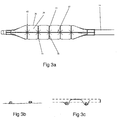
- the fiber braid protrudes from the surface of the balloon ( Figure 3b ) or is formed with the balloon surface (when sandwiched between two layers of balloon wall material) such that the balloon wall does not extend radially outwardly beyond the fiber braid.
- the isolated balloon regions protrude from the braid openings to a height that is defined as the distance between the surface of the braid fiber and outermost surface of the isolated balloon regions (arrow, Figure 3c ).
- Such a height can be at least about 0.1 mm, and in some implementations at least about 0.1 or 0.2 or more, at the nominal inflated working pressure. In general, the height will be within the rage of from about 0.01-1 mm or 0.1-0.5 mm.
- assembly of the fibers is effected over a balloon inflated to about 3 mm in diameter.
- protrusions of the isolated balloon regions will for at this diameter, and will gradually increase in height along with inflation.
- the height of the isolated balloon regions protruding from the balloon surface will begin at 3.5 mm and gradually increase in height with inflation, typically to about 0.01-0.5 mm in increased height.
- the fibers are preferably attached to the balloon surface along the entire length of each fiber. Attachment is effected using an adhesive applied to the fibers or by sandwiching the fibers between two adhesive layers applied to the balloon surface, a base and cover adhesive layer. These layers can be applied via dipping, spraying, or any other approach known in the art.
- the base layer of the balloon wall can be any flexible adhesive layer that allows for immobilization of the fibers but retains the flexibility of the underlying balloon substrate while the cover layer further immobilizes the grid, protects it from the vessel wall and plaque and enhances vascular wall-gripping.
- a smooth cover layer is particularly advantageous when the present balloon catheter is utilized for dilating in-stent restenosis.
- the cover layer of the present balloon prevents 'stent jailing' - a phenomenon in which struts of, for example, cutting/scoring balloons, are trapped within stent struts.
- Attachment or partial-attachment of the fibers to the balloon surface may be desirable in order to maintain fiber position over the balloon throughout inflation, and thus maintain the shape and size of the isolated balloon regions. If the fibers were free to move the uniformity of balloon protrusions could not be maintained and thus uniform vessel dilation would not be possible. Fixation of the fibers in a specific grid shape is also very important over the balloon tapers where a free wire would tend to slip from its intended position more easily, again resulting in protrusion non-uniformity.
- the fibers are braided over the balloon working length at a lead angle as defined by the PPI.
- the angle can vary from 30-180 degrees.
- each isolated balloon region protruding between channels
- four crossing fibers angled at approximately 90 degrees to each other. Since the lead angle is constant and equal for all fibers, the isolated balloon regions formed between the fibers are square/rectangle. At this configuration, the fibers are positioned to resist tension forces applied thereupon by the pressure buildup in the balloon.
- the fibers are braided lengthwise and radially, however, the present grid can also be formed by helical braiding of fibers over the working length and tapers of the balloon.
- top layer can be applied to the balloon following sandwiching of the fiber grid between the base and cover layers. This top layer decreases the tackiness of the balloon and improves its ability to track through a tortuous anatomy and inflate within the vessel site.
- the top layer can be composed of parylene or any other material commonly known in the art.
- the balloon can be coated with a coating following sandwiching of the fiber grid between the base and cover layers.
- This coating can be a hydrophilic material or a hydrophobic material.
- the coating decreases the tackiness of the balloon and improves its ability to track through a tortuous anatomy and inflate within the vessel site.
- the top layer can be composed of silicone, polyurethane, polyvinylpyrrolidone, hyaluronic acid, or any other material commonly known in the art.
- the balloon When assembled the balloon can be folded in regular folding techniques known in the art.
- the balloon can be folded to 2 - 8 pleats, with the pleats being wrapped around the balloon axis as done with plain balloon.
- the fibers are soft enough to allow such folding.
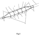
- FIGS 1-4 illustrate one embodiment of the present balloon system, which is referred to herein as system 10.
- System 10 is configured for use in angioplasty procedures.
- System 10 includes a catheter shaft 12, which is fabricated from polymer extrusions and includes longitudinal lumens running the length of shaft 12.
- a first lumen can accommodate a guidewire while a second lumen can serve as an inflation conduit for balloon 20 mounted on a distal portion 14 of shaft 12.
- Proximal portion 16 of shaft 12 includes a connector 18 having dedicated ports 22 and 24 communicating with the second and first lumens (respectively).
- balloon 20 can be between 1.25 to 5.0 mm in diameter and 4 to 40 mm in length (when inflated as shown in Figure 2 ).
- balloon 20 can be between 2 to 12 mm in diameter and 5 to 300 mm in length.
- a longer balloon may taper (radially) along its length.
- the wall thickness of balloon 20 can vary from 1 - 250 ⁇ m (variable depending on material and specified characteristics). The balloon wall thickness can be uniform or variable.
- Balloon 20 is attached to distal portion 14 of shaft 12 using approaches well known in the art (e.g. gluing or welding).
- a grid 30 is integrated into, or glued onto wall 32 of balloon 20 as is described above.
- Grid 30 is formed from two or more fibers 34 (five radial fibers 35 and four axial fibers 37 shown in Figure 2 ) that are braided/woven over the length of balloon 20 including working length (WL), legs (LG) and tapers (TP).
- grid 30 when balloon 20 is inflated to nominal pressure e.g. 6-20 ATMs (1 ATM ⁇ 101 kPa), grid 30 enables isolated balloon regions 36 to protrude through openings 38 formed between fibers 34 and form channels 40 in the balloon surface.
- isolated balloon regions 36 can protrude 0.01-0.5 mm from the balloon surface.
- the grid 30 can include a number of circumferential fiber portions intersecting a number of axial fiber portions. In general, there can be about 3 to about 20 circumferential fiber portions, such as about 4 to about 10 circumferential fiber portions, and about 3 to about 10 axial fiber portions, such as about 3 to about 5 axial fiber portions. In some implementations, there can be about 10 to about 20 isolated balloon regions, such as about 12 to about 18 balloon regions or about 14 to about 16 balloon regions.
- isolated balloon regions 36 contact the plaque in the vessel and apply a uniform force thereto, while channels 40 (which are recessed from the plaque) function as stress relief regions.
- Fibers 34 can be laid down in any pattern as long as the grid formed thereby includes openings 38 of roughly the same area and shape.
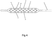
- fibers 34 can be laid down longitudinally (axially) and radially to form square or rectangular openings 38 (as is shown in Figures 2-3 ), or fibers 34 can be helically wound clockwise and counterclockwise to form diamond-shaped openings 38 as is shown in Figure 4 which illustrates a grid 30 formed from helically wound fibers 34.
- a combination of these two approaches can also be used by providing axial fibers to limit balloon elongation and form triangular-shaped openings 38 ( Figure 5 ).
- the number of fibers 34 correlates to the density of the braid forming the grid and the number of and area of openings 38 (forming isolated balloon regions 36).
- a balloon 20 that is 40 mm in length and 6.0 mm in diameter includes a braided grid 30 formed from 8 fibers 34, 4 longitudinal fibers 34 and 4 radially wound fibers 34. This braiding pattern forms triangular and hexagonal - shaped isolated balloon regions 3 when inflated.
- balloon 20 can include helical (H) + longitudinal (L) fibers 34 (wherein the number of H fibers is greater than the number of L fibers), with L fibers longitudinally arranged around the balloon, H/2 fibers 34 helically wrapped clockwise and H/2 fibers 34 helically wrapped counterclockwise. This result in a grid 30 forming triangular and hexagonal -shaped openings 38 through which isolated balloon regions 36 protrude around the circumference of balloon 20.
- Grid 30 preferably has a variable pitch (fiber 34 angles) over the working length (WL), legs (LG), and tapers (TP) of balloon 20 ( Figure 2 ). Such variation can accommodate for changes in balloon 20 diameters over its length (e.g. taper expands less than working length) or can alter the local compliance of a balloon region (e.g. make a taper region less compliant).
- System 10 can be used in angioplasty as follows. System 10 can be guided to the stenosed region over a guide-wire (not shown) using well known angioplasty approaches. Once in position, balloon 20 can be inflated to a point where it channels 40 and isolated balloon regions 36 are formed to apply an outward radial force to the plaque at isolated balloon regions 36 and stress relief regions at channels 40. Once the region is sufficiently dilated, balloon 20 is deflated and system 10 is removed from the body.
- the present disclosure provides a balloon system, which protects the vessel wall from uneven expansion, as well as enables provision of localized higher pressure forces to specific lesion regions that are resistant, such as highly calcified expansion-resistant plaque regions.
- Balloon 20 of system 10 and/or grid 30 can be coated with a hydrophilic or hydrophobic coating to enhance lubricity or coated with a drug composition containing, for example, an antiproliferative drug such as sirolimus or paclitaxel using methods well known in the art.
- a nylon balloon was fabricated via blow molding and the balloon was pre-inflated to 0.3 atm.
- the balloon was dip-coated in a polyurethane adhesive and an ultra-high molecular weight polyethylene multifilament fiber was braided in a diamond pattern over the balloon surface.
- the balloon was then dip-coated in a second layer of the polyurethane adhesive followed by dip-coating in parylene.
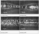
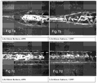
- Figures 8 and 9 illustrate an inflated balloon prototype with a diamond braiding pattern. The balloons were dried and folded to determine the folded diameter.
- Table 1 summarizes the results with the 5 tested balloons.
- N/A N/A N/A N/A a-d are shown in Figure 5 and denote the following: a-(alpha) is the angle of intersection for the fibers as marked in the drawing b- is the distance between longitudinal fibers c- is the length of longitudinal fiber as marked in the drawing d- is the distance as marked in the drawing * 1 ATM ⁇ 101 kPa
Claims (13)
- Système pour dilater un vaisseau sténosé, comprenant :(a) un ballonnet monté sur un corps de cathéter, ledit ballonnet étant composé d'un premier matériau ; et(b) une pluralité de fibres formant un treillis, chacune de ladite pluralité de fibres étant collée ou soudée à une surface dudit ballonnet ou intégrée dans une paroi de celui-ci, ladite pluralité de fibres étant composée d'un second matériau ayant moins d'élasticité que ledit premier matériau, de sorte que lorsque ledit ballonnet est gonflé au-delà d'une pression préétablie une pluralité de régions du ballonnet font saillie dudit treillis formé par ladite pluralité de fibres.
- Système selon la revendication 1, dans lequel ledit ballonnet est composé d'un premier polymère et ladite pluralité de fibres sont composées d'un second polymère.
- Système selon la revendication 1 ou 2, dans lequel une épaisseur de chacune de ladite pluralité de fibres est choisie dans une plage de 10 à 750 micromètres (10 × 10-6 m - 750 × 10-6 m).
- Système selon l'une quelconque des revendications précédentes, dans lequel une épaisseur de chacune de ladite pluralité de fibres varie le long de sa longueur.
- Système selon l'une quelconque des revendications précédentes, dans lequel ledit treillis forme une pluralité de cellules ayant une superficie choisie dans une plage de 1 à 25 mm2.
- Système selon l'une quelconque des revendications précédentes, dans lequel un module d'élasticité en traction de chacune de ladite pluralité de fibres est choisi dans une plage de 1-150 GPa, et ledit module d'élasticité en traction dudit ballonnet est choisi dans une plage de 0,0002-0,0100 GPa.
- Système selon l'une quelconque des revendications précédentes, dans lequel une masse linéique de chacune de ladite pluralité de fibres est de 50 deniers (5,555 × 10-6 kg/m).
- Système selon l'une quelconque des revendications précédentes, dans lequel ledit motif de treillis est formé par N fibres enroulées en hélice autour dudit ballonnet dans un sens des aiguilles d'une montre et N fibres enroulées en hélice autour dudit ballonnet dans un sens inverse des aiguilles d'une montre.
- Système selon la revendication 8, dans lequel N est choisi dans une plage de 4 à 16.
- Système selon l'une quelconque des revendications précédentes, dans lequel ledit treillis est intercalé entre ledit ballonnet et une couche de matériau.
- Système selon l'une quelconque des revendications précédentes, dans lequel chacune de ladite pluralité de fibres est composée de polypropylène, PLLA, PEEK, Kevlar, et/ou polyéthylène à ultra-haut poids moléculaire.
- Système selon l'une quelconque des revendications précédentes, dans lequel ledit ballonnet et/ou ladite pluralité de fibres sont revêtus avec une composition contenant un médicament.
- Système selon la revendication 12, dans lequel ledit médicament est un médicament antiprolifératif.
Applications Claiming Priority (2)
| Application Number | Priority Date | Filing Date | Title |
|---|---|---|---|
| US201462080831P | 2014-11-17 | 2014-11-17 | |
| PCT/IB2015/058802 WO2016079649A1 (fr) | 2014-11-17 | 2015-11-13 | Système de cathéter à ballonnet |
Publications (2)
| Publication Number | Publication Date |
|---|---|
| EP3220994A1 EP3220994A1 (fr) | 2017-09-27 |
| EP3220994B1 true EP3220994B1 (fr) | 2021-01-06 |
Family
ID=54695811
Family Applications (1)
| Application Number | Title | Priority Date | Filing Date |
|---|---|---|---|
| EP15798252.1A Active EP3220994B1 (fr) | 2014-11-17 | 2015-11-13 | Système de cathéter à ballonnet |
Country Status (6)
| Country | Link |
|---|---|
| US (2) | US10232148B2 (fr) |
| EP (1) | EP3220994B1 (fr) |
| JP (1) | JP6803838B2 (fr) |
| CN (1) | CN107106822B (fr) |
| HK (1) | HK1243015A1 (fr) |
| WO (1) | WO2016079649A1 (fr) |
Families Citing this family (29)
| Publication number | Priority date | Publication date | Assignee | Title |
|---|---|---|---|---|
| US9199066B2 (en) | 2010-03-12 | 2015-12-01 | Quattro Vascular Pte Ltd. | Device and method for compartmental vessel treatment |
| SG11201403991RA (en) | 2012-02-01 | 2014-09-26 | Quattro Vascular Pte Ltd | Device for compartmental dilatation of blood vessels |
| CN104168859B (zh) | 2012-02-08 | 2016-06-29 | 夸超脉管私人有限公司 | 具有非线性轴向支柱的约束结构 |
| US9216033B2 (en) | 2012-02-08 | 2015-12-22 | Quattro Vascular Pte Ltd. | System and method for treating biological vessels |
| GB201307066D0 (en) * | 2013-04-18 | 2013-05-29 | Airbus Operations Ltd | Winglet and braided composite spar |
| US10485949B2 (en) | 2013-04-24 | 2019-11-26 | Loma Vista Medical, Inc. | Inflatable medical balloons with continuous fiber wind |
| EP3220994B1 (fr) | 2014-11-17 | 2021-01-06 | TriReme Medical, LLC | Système de cathéter à ballonnet |
| US10182841B1 (en) * | 2015-06-16 | 2019-01-22 | C.R. Bard, Inc. | Medical balloon with enhanced focused force control |
| EP3468654A1 (fr) * | 2016-06-14 | 2019-04-17 | Boston Scientific Scimed, Inc. | Ballonnet médical |
| JP6771970B2 (ja) * | 2016-07-04 | 2020-10-21 | 株式会社カネカ | バルーンカテーテル |
| US20180104458A1 (en) * | 2016-10-17 | 2018-04-19 | Cook Medical Technologies Llc | Shape controlled balloon catheter |
| WO2018111898A1 (fr) | 2016-12-13 | 2018-06-21 | Boston Scientific Scimed, Inc. | Ballonnet médical |
| US10987496B2 (en) | 2017-04-25 | 2021-04-27 | Boston Scientific Scimed, Inc. | Medical balloon |
| CN107137125B (zh) * | 2017-06-20 | 2023-08-04 | 微创神通医疗科技(上海)有限公司 | 取栓支架及取栓装置 |
| CN107582130A (zh) * | 2017-09-25 | 2018-01-16 | 杭州巴泰医疗器械有限公司 | 一种非植入式球囊导管的约束支架及应用该约束支架的血管扩张装置 |
| CN107550610A (zh) * | 2017-09-25 | 2018-01-09 | 杭州巴泰医疗器械有限公司 | 一种非植入式球囊导管的高强度约束支架及应用该约束支架的血管扩张装置 |
| US10779870B2 (en) | 2017-10-16 | 2020-09-22 | Medtronic Holding Company Sarl | Curved inflatable bone tamp with variable wall thickness |
| JP7235763B2 (ja) * | 2018-03-09 | 2023-03-08 | シー・アール・バード・インコーポレーテッド | 連続的な繊維を含む膨張可能な医療用バルーン |
| CN112912126A (zh) * | 2018-08-29 | 2021-06-04 | 波士顿科学国际有限公司 | 多球囊腔形成装置 |
| CN110548210B (zh) * | 2019-10-09 | 2024-02-20 | 四川省肿瘤医院 | 一种防止失压所形成的棱角损伤尿道的导尿管 |
| US20220273915A1 (en) * | 2021-02-26 | 2022-09-01 | Alucent Biomedical, Inc. | Apparatus and methods for restoring tissue |
| WO2023224900A1 (fr) * | 2022-05-16 | 2023-11-23 | Boston Scientific Scimed, Inc. | Ballonnet médical renforcé |
| WO2024018082A1 (fr) | 2022-07-22 | 2024-01-25 | Bvs - Best Vascular Solutions Gmbh | Dispositif de cathéter à ballonnet pour la dilatation atraumatique d'organes creux et procédé de fabrication d'un tel dispositif de cathéter à ballonnet |
| DE102022122630A1 (de) | 2022-07-22 | 2024-01-25 | Bvs - Best Vascular Solutions Gmbh | Ballonkathetervorrichtung zur atraumatischen Behandlung von Hohlorganen sowie ein Verfahren zur Herstellung einer solchen Ballonkathetervorrichtung |
| CN115054811A (zh) * | 2022-08-18 | 2022-09-16 | 山东瑞安泰医疗技术有限公司 | 一种能形成内源性血管支架的药物球囊导管装置 |
| CN115350383B (zh) * | 2022-08-30 | 2023-05-23 | 铂珑生物科技(苏州)有限公司 | 一种球囊导管系统 |
| CN115569294A (zh) * | 2022-09-02 | 2023-01-06 | 杭州矩正医疗科技有限公司 | 载药微针球囊扩张导管及其制备方法 |
| WO2024045982A1 (fr) * | 2022-09-02 | 2024-03-07 | 杭州矩正医疗科技有限公司 | Cathéter à ballonnet de support de médicament et sa méthode de préparation, système de cathéter à ballonnet et méthode de génération de stent intravasculaire in situ |
| CN115554578B (zh) * | 2022-12-05 | 2023-04-28 | 苏州天鸿盛捷医疗器械有限公司 | 球囊用约束装置、其制备方法及血管扩张器械 |
Family Cites Families (168)
| Publication number | Priority date | Publication date | Assignee | Title |
|---|---|---|---|---|
| US2701559A (en) | 1951-08-02 | 1955-02-08 | William A Cooper | Apparatus for exfoliating and collecting diagnostic material from inner walls of hollow viscera |
| US2854983A (en) | 1957-10-31 | 1958-10-07 | Arnold M Baskin | Inflatable catheter |
| US3045677A (en) | 1960-05-03 | 1962-07-24 | American Cystoscope Makers Inc | Inflatable balloon catheter |
| US3467101A (en) | 1965-09-30 | 1969-09-16 | Edwards Lab Inc | Balloon catheter |
| US3825013A (en) | 1973-03-12 | 1974-07-23 | Mcm Hospital Supplies Inc | Balloon catheter |
| US4327736A (en) | 1979-11-20 | 1982-05-04 | Kanji Inoue | Balloon catheter |
| US4483340A (en) | 1980-10-20 | 1984-11-20 | Thomas J. Fogarty | Dilatation catheter |
| US4456011A (en) | 1980-12-22 | 1984-06-26 | Irene Warnecke | Balloon-catheter |
| US4637396A (en) | 1984-10-26 | 1987-01-20 | Cook, Incorporated | Balloon catheter |
| US4723549A (en) | 1986-09-18 | 1988-02-09 | Wholey Mark H | Method and apparatus for dilating blood vessels |
| US4796629A (en) | 1987-06-03 | 1989-01-10 | Joseph Grayzel | Stiffened dilation balloon catheter device |
| US5133732A (en) | 1987-10-19 | 1992-07-28 | Medtronic, Inc. | Intravascular stent |
| FR2624747A1 (fr) | 1987-12-18 | 1989-06-23 | Delsanti Gerard | Dispositifs endo-arteriels amovibles destines a reparer des decollements de parois des arteres |
| US4921484A (en) | 1988-07-25 | 1990-05-01 | Cordis Corporation | Mesh balloon catheter device |
| EP0366478B1 (fr) | 1988-10-28 | 1994-01-26 | Kanji Inoue | Cathéter à ballon |
| US5904679A (en) | 1989-01-18 | 1999-05-18 | Applied Medical Resources Corporation | Catheter with electrosurgical cutter |
| US5628746A (en) | 1989-01-18 | 1997-05-13 | Applied Medical Resources Corporation | Dilatation catheter assembly with cutting element and method of using the same |
| US4976711A (en) | 1989-04-13 | 1990-12-11 | Everest Medical Corporation | Ablation catheter with selectively deployable electrodes |
| US5263963A (en) | 1989-09-08 | 1993-11-23 | Advanced Cardiovascular Systems, Inc. | Expandable cage catheter for repairing a damaged blood vessel |
| US5071407A (en) | 1990-04-12 | 1991-12-10 | Schneider (U.S.A.) Inc. | Radially expandable fixation member |
| US5320634A (en) | 1990-07-03 | 1994-06-14 | Interventional Technologies, Inc. | Balloon catheter with seated cutting edges |
| US5196024A (en) | 1990-07-03 | 1993-03-23 | Cedars-Sinai Medical Center | Balloon catheter with cutting edge |
| US5222971A (en) | 1990-10-09 | 1993-06-29 | Scimed Life Systems, Inc. | Temporary stent and methods for use and manufacture |
| US5449372A (en) | 1990-10-09 | 1995-09-12 | Scimed Lifesystems, Inc. | Temporary stent and methods for use and manufacture |
| US5181911A (en) | 1991-04-22 | 1993-01-26 | Shturman Technologies, Inc. | Helical balloon perfusion angioplasty catheter |
| US5190058A (en) | 1991-05-22 | 1993-03-02 | Medtronic, Inc. | Method of using a temporary stent catheter |
| US5224945A (en) | 1992-01-13 | 1993-07-06 | Interventional Technologies, Inc. | Compressible/expandable atherectomy cutter |
| US5176693A (en) | 1992-05-11 | 1993-01-05 | Interventional Technologies, Inc. | Balloon expandable atherectomy cutter |
| US5460607A (en) | 1992-09-30 | 1995-10-24 | Nippon Zeon Co., Ltd. | Balloon catheter |
| US5336178A (en) | 1992-11-02 | 1994-08-09 | Localmed, Inc. | Intravascular catheter with infusion array |
| US5501694A (en) | 1992-11-13 | 1996-03-26 | Scimed Life Systems, Inc. | Expandable intravascular occlusion material removal devices and methods of use |
| US5308356A (en) | 1993-02-25 | 1994-05-03 | Blackshear Jr Perry L | Passive perfusion angioplasty catheter |
| DK171747B1 (da) | 1993-03-02 | 1997-05-05 | Metra Aps | Dilatationskateter |
| US5344419A (en) | 1993-04-23 | 1994-09-06 | Wayne State University | Apparatus and method for making a diffusing tip in a balloon catheter system |
| CA2118886C (fr) | 1993-05-07 | 1998-12-08 | Dennis Vigil | Methode et dispositif de dilatation de vaisseaux stenoses |
| US5456667A (en) | 1993-05-20 | 1995-10-10 | Advanced Cardiovascular Systems, Inc. | Temporary stenting catheter with one-piece expandable segment |
| EP0630659B1 (fr) | 1993-06-23 | 1998-01-21 | Mihai Iacob | Catheter d'angioplastique à perfusion |
| US5484411A (en) * | 1994-01-14 | 1996-01-16 | Cordis Corporation | Spiral shaped perfusion balloon and method of use and manufacture |
| US6245040B1 (en) | 1994-01-14 | 2001-06-12 | Cordis Corporation | Perfusion balloon brace and method of use |
| ATE293395T1 (de) | 1994-01-26 | 2005-05-15 | Kyphon Inc | Verbesserte aufblasbare vorrichtung zur verwendung in chirurgischen protokollen im bezug auf die fixierung von knochen |
| US5643312A (en) | 1994-02-25 | 1997-07-01 | Fischell Robert | Stent having a multiplicity of closed circular structures |
| US5733303A (en) | 1994-03-17 | 1998-03-31 | Medinol Ltd. | Flexible expandable stent |
| US5449373A (en) | 1994-03-17 | 1995-09-12 | Medinol Ltd. | Articulated stent |
| US5562620A (en) | 1994-04-01 | 1996-10-08 | Localmed, Inc. | Perfusion shunt device having non-distensible pouch for receiving angioplasty balloon |
| US5456666A (en) | 1994-04-26 | 1995-10-10 | Boston Scientific Corp | Medical balloon folding into predetermined shapes and method |
| US5810767A (en) | 1994-05-11 | 1998-09-22 | Localmed, Inc. | Method and apparatus for pressurized intraluminal drug delivery |
| WO1996000242A1 (fr) | 1994-06-24 | 1996-01-04 | Human Genome Sciences, Inc. | Recepteur epsilon d'acide retinoique |
| US5575816A (en) | 1994-08-12 | 1996-11-19 | Meadox Medicals, Inc. | High strength and high density intraluminal wire stent |
| US5620457A (en) | 1994-11-23 | 1997-04-15 | Medinol Ltd. | Catheter balloon |
| US5628755A (en) | 1995-02-20 | 1997-05-13 | Schneider (Europe) A.G. | Balloon catheter and stent delivery system |
| US5527282A (en) | 1994-12-09 | 1996-06-18 | Segal; Jerome | Vascular dilatation device and method |
| US5556408A (en) | 1995-04-27 | 1996-09-17 | Interventional Technologies Inc. | Expandable and compressible atherectomy cutter |
| US5730698A (en) | 1995-05-09 | 1998-03-24 | Fischell; Robert E. | Balloon expandable temporary radioisotope stent system |
| US6059810A (en) | 1995-05-10 | 2000-05-09 | Scimed Life Systems, Inc. | Endovascular stent and method |
| NL1000413C2 (nl) | 1995-05-22 | 1996-11-25 | Cordis Europ | Balloncatheter met ballonbeschermingsmantel. |
| US6602281B1 (en) | 1995-06-05 | 2003-08-05 | Avantec Vascular Corporation | Radially expansible vessel scaffold having beams and expansion joints |
| CA2225784A1 (fr) | 1995-06-30 | 1997-01-23 | Boston Scientific Corporation | Catheter pour imagerie ultrasonique, avec un element coupant |
| US5713863A (en) | 1996-01-11 | 1998-02-03 | Interventional Technologies Inc. | Catheter with fluid medication injectors |
| US6102904A (en) | 1995-07-10 | 2000-08-15 | Interventional Technologies, Inc. | Device for injecting fluid into a wall of a blood vessel |
| WO1997004721A1 (fr) | 1995-07-25 | 1997-02-13 | Medstent Inc. | Extenseur |
| US5556382A (en) | 1995-08-29 | 1996-09-17 | Scimed Life Systems, Inc. | Balloon perfusion catheter |
| US5840008A (en) | 1995-11-13 | 1998-11-24 | Localmed, Inc. | Radiation emitting sleeve catheter and methods |
| US5607442A (en) | 1995-11-13 | 1997-03-04 | Isostent, Inc. | Stent with improved radiopacity and appearance characteristics |
| CA2192520A1 (fr) * | 1996-03-05 | 1997-09-05 | Ian M. Penn | Tringle extensible et methode de mise en place de ladite tringle |
| US6334871B1 (en) | 1996-03-13 | 2002-01-01 | Medtronic, Inc. | Radiopaque stent markers |
| US5735816A (en) | 1996-07-23 | 1998-04-07 | Medtronic, Inc. | Spiral sheath retainer for autoperfusion dilatation catheter balloon |
| US7252650B1 (en) * | 1996-08-02 | 2007-08-07 | Ranier Limited | Balloon catheter |
| GB9616267D0 (en) | 1996-08-02 | 1996-09-11 | Ranier Ltd | Balloon catheter |
| US5755781A (en) | 1996-08-06 | 1998-05-26 | Iowa-India Investments Company Limited | Embodiments of multiple interconnected stents |
| US6156265A (en) | 1996-08-19 | 2000-12-05 | Sumitomo Electric Industries, Ltd. | Powder compacting apparatus and method of forming helical gear wheel using said powder compacting apparatus |
| US5797935A (en) | 1996-09-26 | 1998-08-25 | Interventional Technologies Inc. | Balloon activated forced concentrators for incising stenotic segments |
| US5868719A (en) | 1997-01-15 | 1999-02-09 | Boston Scientific Corporation | Drug delivery balloon catheter device |
| US5827321A (en) | 1997-02-07 | 1998-10-27 | Cornerstone Devices, Inc. | Non-Foreshortening intraluminal prosthesis |
| US5868783A (en) | 1997-04-16 | 1999-02-09 | Numed, Inc. | Intravascular stent with limited axial shrinkage |
| US5868708A (en) | 1997-05-07 | 1999-02-09 | Applied Medical Resources Corporation | Balloon catheter apparatus and method |
| EP0888757B1 (fr) | 1997-06-30 | 2004-01-21 | Medex Holding GmbH | Implant intraluminaire |
| US5868779A (en) | 1997-08-15 | 1999-02-09 | Ruiz; Carlos E. | Apparatus and methods for dilating vessels and hollow-body organs |
| US6206910B1 (en) | 1997-09-11 | 2001-03-27 | Wake Forest University | Compliant intraluminal stents |
| US6361545B1 (en) | 1997-09-26 | 2002-03-26 | Cardeon Corporation | Perfusion filter catheter |
| IL135360A (en) | 1997-10-01 | 2005-07-25 | Boston Scient Ltd | Body track dilation systems and related methods |
| US6309414B1 (en) | 1997-11-04 | 2001-10-30 | Sorin Biomedica Cardio S.P.A. | Angioplasty stents |
| US6013055A (en) | 1997-11-13 | 2000-01-11 | Boston Scientific Corporation | Catheter balloon having selected folding characteristics |
| US6241762B1 (en) | 1998-03-30 | 2001-06-05 | Conor Medsystems, Inc. | Expandable medical device with ductile hinges |
| US20030040790A1 (en) | 1998-04-15 | 2003-02-27 | Furst Joseph G. | Stent coating |
| US6626861B1 (en) | 1998-04-22 | 2003-09-30 | Applied Medical Resources | Balloon catheter apparatus and method |
| US6206283B1 (en) | 1998-12-23 | 2001-03-27 | At&T Corp. | Method and apparatus for transferring money via a telephone call |
| US5987661A (en) | 1998-06-25 | 1999-11-23 | Sportsstuff, Inc. | Inflatable swimming pool and supporting net |
| US6261319B1 (en) | 1998-07-08 | 2001-07-17 | Scimed Life Systems, Inc. | Stent |
| US6036708A (en) | 1998-08-13 | 2000-03-14 | Advanced Cardiovascular Systems, Inc. | Cutting stent with flexible tissue extractor |
| US6053913A (en) | 1998-09-10 | 2000-04-25 | Tu; Lily Chen | Rapid exchange stented balloon catheter having ablation capabilities |
| US6036689A (en) | 1998-09-24 | 2000-03-14 | Tu; Lily Chen | Ablation device for treating atherosclerotic tissues |
| US6319251B1 (en) | 1998-09-24 | 2001-11-20 | Hosheng Tu | Medical device and methods for treating intravascular restenosis |
| US5919200A (en) | 1998-10-09 | 1999-07-06 | Hearten Medical, Inc. | Balloon catheter for abrading a patent foramen ovale and method of using the balloon catheter |
| US6190403B1 (en) | 1998-11-13 | 2001-02-20 | Cordis Corporation | Low profile radiopaque stent with increased longitudinal flexibility and radial rigidity |
| US6129706A (en) | 1998-12-10 | 2000-10-10 | Janacek; Jaroslav | Corrugated catheter balloon |
| US6077298A (en) | 1999-02-20 | 2000-06-20 | Tu; Lily Chen | Expandable/retractable stent and methods thereof |
| US6743196B2 (en) | 1999-03-01 | 2004-06-01 | Coaxia, Inc. | Partial aortic occlusion devices and methods for cerebral perfusion augmentation |
| US6258099B1 (en) | 1999-03-31 | 2001-07-10 | Scimed Life Systems, Inc. | Stent security balloon/balloon catheter |
| US6325825B1 (en) | 1999-04-08 | 2001-12-04 | Cordis Corporation | Stent with variable wall thickness |
| US6454775B1 (en) | 1999-12-06 | 2002-09-24 | Bacchus Vascular Inc. | Systems and methods for clot disruption and retrieval |
| US6540722B1 (en) | 1999-12-30 | 2003-04-01 | Advanced Cardiovascular Systems, Inc. | Embolic protection devices |
| US6702834B1 (en) | 1999-12-30 | 2004-03-09 | Advanced Cardiovascular Systems, Inc. | Embolic protection devices |
| US6695813B1 (en) | 1999-12-30 | 2004-02-24 | Advanced Cardiovascular Systems, Inc. | Embolic protection devices |
| US20010031981A1 (en) | 2000-03-31 | 2001-10-18 | Evans Michael A. | Method and device for locating guidewire and treating chronic total occlusions |
| KR100360364B1 (ko) | 2000-05-22 | 2002-11-13 | 주식회사 정성메디칼 | 관상동맥 설치용 금속 스텐트 |
| EP1305078B1 (fr) | 2000-07-24 | 2011-06-29 | Jeffrey Grayzel | Sonde a ballonnet rigide de dilatation et de mise en place de stent |
| US20020161388A1 (en) | 2001-02-27 | 2002-10-31 | Samuels Sam L. | Elastomeric balloon support fabric |
| US6942689B2 (en) | 2001-03-01 | 2005-09-13 | Cordis Corporation | Flexible stent |
| US6500186B2 (en) | 2001-04-17 | 2002-12-31 | Scimed Life Systems, Inc. | In-stent ablative tool |
| KR20040030423A (ko) | 2001-08-08 | 2004-04-09 | 가네가후치 가가쿠 고교 가부시키가이샤 | 확장 카테터 |
| US6656351B2 (en) | 2001-08-31 | 2003-12-02 | Advanced Cardiovascular Systems, Inc. | Embolic protection devices one way porous membrane |
| US20040111108A1 (en) | 2001-11-09 | 2004-06-10 | Farnan Robert C. | Balloon catheter with non-deployable stent |
| US7691119B2 (en) | 2001-11-09 | 2010-04-06 | Angioscore, Inc. | Balloon catheter with non-deployable stent |
| US7241304B2 (en) | 2001-12-21 | 2007-07-10 | Advanced Cardiovascular Systems, Inc. | Flexible and conformable embolic filtering devices |
| US20030212449A1 (en) | 2001-12-28 | 2003-11-13 | Cox Daniel L. | Hybrid stent |
| US7029493B2 (en) | 2002-01-25 | 2006-04-18 | Cordis Corporation | Stent with enhanced crossability |
| US7186237B2 (en) | 2002-02-14 | 2007-03-06 | Avantec Vascular Corporation | Ballon catheter for creating a longitudinal channel in a lesion and method |
| US20030195609A1 (en) | 2002-04-10 | 2003-10-16 | Scimed Life Systems, Inc. | Hybrid stent |
| IL149828A (en) | 2002-05-23 | 2007-09-20 | Ronnie Levi | Medical device having a tubular portion |
| CA2484383C (fr) | 2002-07-12 | 2016-05-31 | Cook Incorporated | Appareil medical recouvert d'un agent bioactif |
| DE10244847A1 (de) | 2002-09-20 | 2004-04-01 | Ulrich Prof. Dr. Speck | Medizinische Vorrichtung zur Arzneimittelabgabe |
| US7686824B2 (en) | 2003-01-21 | 2010-03-30 | Angioscore, Inc. | Apparatus and methods for treating hardened vascular lesions |
| US8080026B2 (en) | 2003-01-21 | 2011-12-20 | Angioscore, Inc. | Apparatus and methods for treating hardened vascular lesions |
| US7156869B1 (en) | 2003-01-27 | 2007-01-02 | Advanced Cardiovascular Systems, Inc. | Drug-eluting stent and delivery system with tapered stent in shoulder region |
| US6958073B2 (en) | 2003-04-21 | 2005-10-25 | Medtronic Vascular, Inc. | Method and system for stent retention using an adhesive |
| US7198637B2 (en) * | 2003-04-21 | 2007-04-03 | Medtronic Vascular, Inc. | Method and system for stent retention using an adhesive |
| US6846323B2 (en) | 2003-05-15 | 2005-01-25 | Advanced Cardiovascular Systems, Inc. | Intravascular stent |
| US20050271844A1 (en) | 2004-06-07 | 2005-12-08 | Scimed Life Systems, Inc. | Artificial silk reinforcement of PTCA balloon |
| US7635510B2 (en) | 2004-07-07 | 2009-12-22 | Boston Scientific Scimed, Inc. | High performance balloon catheter/component |
| US8715229B2 (en) * | 2004-10-15 | 2014-05-06 | Bard Peripheral Vascular, Inc. | Non-compliant medical balloon having braided or knitted reinforcement |
| US20060085058A1 (en) | 2004-10-20 | 2006-04-20 | Rosenthal Arthur L | System and method for delivering a biologically active material to a body lumen |
| US7753907B2 (en) | 2004-10-29 | 2010-07-13 | Boston Scientific Scimed, Inc. | Medical device systems and methods |
| DE602005010906D1 (de) | 2004-12-30 | 2008-12-18 | Cook Inc | Katheteranordnung mit plaqueschneideballon |
| CA2596490A1 (fr) * | 2005-02-09 | 2006-08-17 | Angiodynamics, Inc. | Ballonnet renforce pour catheter |
| US7585308B2 (en) | 2005-03-30 | 2009-09-08 | Ethicon Endo-Surgery, Inc. | Handle system and method for use in anastomotic procedures |
| US10076641B2 (en) | 2005-05-11 | 2018-09-18 | The Spectranetics Corporation | Methods and systems for delivering substances into luminal walls |
| US8672990B2 (en) * | 2005-05-27 | 2014-03-18 | Boston Scientific Scimed, Inc. | Fiber mesh controlled expansion balloon catheter |
| WO2007024964A1 (fr) | 2005-08-22 | 2007-03-01 | Incept, Llc | Stents evases, appareil et procedes de production et d'utilisation |
| US20070173923A1 (en) | 2006-01-20 | 2007-07-26 | Savage Douglas R | Drug reservoir stent |
| US8333000B2 (en) | 2006-06-19 | 2012-12-18 | Advanced Cardiovascular Systems, Inc. | Methods for improving stent retention on a balloon catheter |
| US8388573B1 (en) | 2006-06-28 | 2013-03-05 | Abbott Cardiovascular Systems Inc. | Local delivery with a balloon covered by a cage |
| US8414525B2 (en) | 2006-11-20 | 2013-04-09 | Lutonix, Inc. | Drug releasing coatings for medical devices |
| US9370642B2 (en) | 2007-06-29 | 2016-06-21 | J.W. Medical Systems Ltd. | Adjustable-length drug delivery balloon |
| US20090036964A1 (en) | 2007-08-01 | 2009-02-05 | Prescient Medical, Inc. | Expandable Prostheses for Treating Atherosclerotic Lesions Including Vulnerable Plaques |
| DE102008006092A1 (de) | 2008-01-25 | 2009-07-30 | Biotronik Vi Patent Ag | Mehrfachmembranballon und Verfahren zur Herstellung eines Mehrfachmembranballons |
| JP5662165B2 (ja) * | 2008-02-25 | 2015-01-28 | メイヨ・ファウンデーション・フォー・メディカル・エデュケーション・アンド・リサーチ | 形状適合性ステントおよび製造方法 |
| EP2594311A3 (fr) | 2008-03-06 | 2013-07-10 | Boston Scientific Scimed, Inc. | Dispositifs de cathéter à ballonnet avec protection gainée |
| EP2262443A2 (fr) | 2008-03-10 | 2010-12-22 | NFocus Neuromedical, Inc. | Stents et greffons pour stent |
| US9480826B2 (en) | 2008-03-21 | 2016-11-01 | Cagent Vascular, Llc | Intravascular device |
| JP5846905B2 (ja) | 2008-03-21 | 2016-01-20 | ケイジェント ヴァスキュラー, エルエルシーCagent Vascular, Llc | 血管内でのアテローム斑の穿孔およびセレーションのための血管内装置 |
| CA2741685A1 (fr) * | 2008-10-30 | 2010-05-06 | R4 Vascular, Inc. | Ballonnet de catheter radio-opaque souple resistant a la rupture et procedes pour l'utiliser dans une intervention chirurgicale intravasculaire |
| GB2468861B (en) | 2009-03-23 | 2011-05-18 | Cook William Europ | Conformable stent structure and method of making same |
| US8425587B2 (en) | 2009-09-17 | 2013-04-23 | Abbott Cardiovascular Systems Inc. | Method of treatment with a bioabsorbable stent with time dependent structure and properties and regio-selective degradation |
| US8298279B2 (en) | 2009-09-24 | 2012-10-30 | Medtronic Vascular, Inc. | Stent including a toggle lock strut |
| US8348987B2 (en) | 2009-12-22 | 2013-01-08 | Cook Medical Technologies Llc | Balloon with scoring member |
| US9199066B2 (en) * | 2010-03-12 | 2015-12-01 | Quattro Vascular Pte Ltd. | Device and method for compartmental vessel treatment |
| EP2380605A1 (fr) | 2010-04-19 | 2011-10-26 | InnoRa Gmbh | Formulations améliorées pour dispositifs médicaux revêtus de médicaments |
| EP2593170A1 (fr) * | 2010-07-16 | 2013-05-22 | Abbott Cardiovascular Systems Inc. | Dispositif médical comprenant un élément qui rentre en contact avec les tissus et procédé de délivrance d'un agent thérapeutique |
| US8632559B2 (en) | 2010-09-21 | 2014-01-21 | Angioscore, Inc. | Method and system for treating valve stenosis |
| US8961457B2 (en) * | 2010-09-30 | 2015-02-24 | Surmodics, Inc. | Catheter assembly with guard |
| US9730726B2 (en) | 2011-10-07 | 2017-08-15 | W. L. Gore & Associates, Inc. | Balloon assemblies having controllably variable topographies |
| US9415140B2 (en) | 2011-10-14 | 2016-08-16 | Innora Gmbh | Formulations for drug-coated medical devices |
| SG11201403991RA (en) | 2012-02-01 | 2014-09-26 | Quattro Vascular Pte Ltd | Device for compartmental dilatation of blood vessels |
| CN104168859B (zh) | 2012-02-08 | 2016-06-29 | 夸超脉管私人有限公司 | 具有非线性轴向支柱的约束结构 |
| US9216033B2 (en) | 2012-02-08 | 2015-12-22 | Quattro Vascular Pte Ltd. | System and method for treating biological vessels |
| US9669194B2 (en) | 2013-03-14 | 2017-06-06 | W. L. Gore & Associates, Inc. | Conformable balloon devices and methods |
| US9782571B2 (en) * | 2014-01-30 | 2017-10-10 | Chuter A. M. Timothy | Flexible high-pressure angioplasty balloons |
| EP3220994B1 (fr) | 2014-11-17 | 2021-01-06 | TriReme Medical, LLC | Système de cathéter à ballonnet |
-
2015
- 2015-11-13 EP EP15798252.1A patent/EP3220994B1/fr active Active
- 2015-11-13 US US14/941,480 patent/US10232148B2/en active Active
- 2015-11-13 CN CN201580062444.0A patent/CN107106822B/zh active Active
- 2015-11-13 WO PCT/IB2015/058802 patent/WO2016079649A1/fr active Application Filing
- 2015-11-13 JP JP2017526522A patent/JP6803838B2/ja active Active
-
2018
- 2018-02-23 HK HK18102628.6A patent/HK1243015A1/zh unknown
-
2019
- 2019-01-28 US US16/259,232 patent/US11000680B2/en active Active
Non-Patent Citations (1)
| Title |
|---|
| None * |
Also Published As
| Publication number | Publication date |
|---|---|
| US10232148B2 (en) | 2019-03-19 |
| EP3220994A1 (fr) | 2017-09-27 |
| CN107106822B (zh) | 2021-05-04 |
| HK1243015A1 (zh) | 2018-07-06 |
| JP2017533787A (ja) | 2017-11-16 |
| US20190151627A1 (en) | 2019-05-23 |
| CN107106822A (zh) | 2017-08-29 |
| US20160136397A1 (en) | 2016-05-19 |
| US11000680B2 (en) | 2021-05-11 |
| WO2016079649A1 (fr) | 2016-05-26 |
| JP6803838B2 (ja) | 2020-12-23 |
Similar Documents
| Publication | Publication Date | Title |
|---|---|---|
| US11000680B2 (en) | Balloon catheter system and method of using same | |
| JP7309643B2 (ja) | バルーンアセンブリ | |
| AU2009308781B2 (en) | Rupture-resistant compliant radiopaque catheter balloon and methods for use of same in an intravascular surgical procedure | |
| US8979886B2 (en) | Medical balloon and method of making the same | |
| US7682335B2 (en) | Non-compliant medical balloon having an integral non-woven fabric layer | |
| US8323546B2 (en) | Non-compliant medical balloon having an integral woven fabric layer | |
| US10617849B2 (en) | Balloon with variable pitch reinforcing fibers | |
| WO2020195697A1 (fr) | Cathéter à ballonnet | |
| WO2018008514A1 (fr) | Sonde à ballonnet. | |
| JP2018000633A (ja) | バルーンカテーテル | |
| JP7321254B2 (ja) | S字状繊維を含む膨張可能な医療用バルーン | |
| EP4333956A1 (fr) | Ballonnet médical gonflable à diamètre variable | |
| WO2017106358A1 (fr) | Ballonnet de cathéter radio-opaque souple résistant à la rupture et procédés d'utilisation associés au cours d'une intervention chirurgicale intravasculaire |
Legal Events
| Date | Code | Title | Description |
|---|---|---|---|
| STAA | Information on the status of an ep patent application or granted ep patent |
Free format text: STATUS: THE INTERNATIONAL PUBLICATION HAS BEEN MADE |
|
| PUAI | Public reference made under article 153(3) epc to a published international application that has entered the european phase |
Free format text: ORIGINAL CODE: 0009012 |
|
| STAA | Information on the status of an ep patent application or granted ep patent |
Free format text: STATUS: REQUEST FOR EXAMINATION WAS MADE |
|
| 17P | Request for examination filed |
Effective date: 20170616 |
|
| AK | Designated contracting states |
Kind code of ref document: A1 Designated state(s): AL AT BE BG CH CY CZ DE DK EE ES FI FR GB GR HR HU IE IS IT LI LT LU LV MC MK MT NL NO PL PT RO RS SE SI SK SM TR |
|
| AX | Request for extension of the european patent |
Extension state: BA ME |
|
| DAV | Request for validation of the european patent (deleted) | ||
| DAX | Request for extension of the european patent (deleted) | ||
| RAP1 | Party data changed (applicant data changed or rights of an application transferred) |
Owner name: TRIREME MEDICAL, LLC |
|
| GRAP | Despatch of communication of intention to grant a patent |
Free format text: ORIGINAL CODE: EPIDOSNIGR1 |
|
| STAA | Information on the status of an ep patent application or granted ep patent |
Free format text: STATUS: GRANT OF PATENT IS INTENDED |
|
| INTG | Intention to grant announced |
Effective date: 20200730 |
|
| GRAS | Grant fee paid |
Free format text: ORIGINAL CODE: EPIDOSNIGR3 |
|
| GRAA | (expected) grant |
Free format text: ORIGINAL CODE: 0009210 |
|
| STAA | Information on the status of an ep patent application or granted ep patent |
Free format text: STATUS: THE PATENT HAS BEEN GRANTED |
|
| AK | Designated contracting states |
Kind code of ref document: B1 Designated state(s): AL AT BE BG CH CY CZ DE DK EE ES FI FR GB GR HR HU IE IS IT LI LT LU LV MC MK MT NL NO PL PT RO RS SE SI SK SM TR |
|
| REG | Reference to a national code |
Ref country code: GB Ref legal event code: FG4D |
|
| REG | Reference to a national code |
Ref country code: AT Ref legal event code: REF Ref document number: 1351683 Country of ref document: AT Kind code of ref document: T Effective date: 20210115 Ref country code: CH Ref legal event code: EP |
|
| REG | Reference to a national code |
Ref country code: DE Ref legal event code: R096 Ref document number: 602015064482 Country of ref document: DE |
|
| REG | Reference to a national code |
Ref country code: IE Ref legal event code: FG4D |
|
| REG | Reference to a national code |
Ref country code: NL Ref legal event code: FP |
|
| REG | Reference to a national code |
Ref country code: AT Ref legal event code: MK05 Ref document number: 1351683 Country of ref document: AT Kind code of ref document: T Effective date: 20210106 |
|
| REG | Reference to a national code |
Ref country code: LT Ref legal event code: MG9D |
|
| PG25 | Lapsed in a contracting state [announced via postgrant information from national office to epo] |
Ref country code: FI Free format text: LAPSE BECAUSE OF FAILURE TO SUBMIT A TRANSLATION OF THE DESCRIPTION OR TO PAY THE FEE WITHIN THE PRESCRIBED TIME-LIMIT Effective date: 20210106 Ref country code: HR Free format text: LAPSE BECAUSE OF FAILURE TO SUBMIT A TRANSLATION OF THE DESCRIPTION OR TO PAY THE FEE WITHIN THE PRESCRIBED TIME-LIMIT Effective date: 20210106 Ref country code: GR Free format text: LAPSE BECAUSE OF FAILURE TO SUBMIT A TRANSLATION OF THE DESCRIPTION OR TO PAY THE FEE WITHIN THE PRESCRIBED TIME-LIMIT Effective date: 20210407 Ref country code: BG Free format text: LAPSE BECAUSE OF FAILURE TO SUBMIT A TRANSLATION OF THE DESCRIPTION OR TO PAY THE FEE WITHIN THE PRESCRIBED TIME-LIMIT Effective date: 20210406 Ref country code: NO Free format text: LAPSE BECAUSE OF FAILURE TO SUBMIT A TRANSLATION OF THE DESCRIPTION OR TO PAY THE FEE WITHIN THE PRESCRIBED TIME-LIMIT Effective date: 20210406 Ref country code: PT Free format text: LAPSE BECAUSE OF FAILURE TO SUBMIT A TRANSLATION OF THE DESCRIPTION OR TO PAY THE FEE WITHIN THE PRESCRIBED TIME-LIMIT Effective date: 20210506 Ref country code: LT Free format text: LAPSE BECAUSE OF FAILURE TO SUBMIT A TRANSLATION OF THE DESCRIPTION OR TO PAY THE FEE WITHIN THE PRESCRIBED TIME-LIMIT Effective date: 20210106 |
|
| PG25 | Lapsed in a contracting state [announced via postgrant information from national office to epo] |
Ref country code: PL Free format text: LAPSE BECAUSE OF FAILURE TO SUBMIT A TRANSLATION OF THE DESCRIPTION OR TO PAY THE FEE WITHIN THE PRESCRIBED TIME-LIMIT Effective date: 20210106 Ref country code: LV Free format text: LAPSE BECAUSE OF FAILURE TO SUBMIT A TRANSLATION OF THE DESCRIPTION OR TO PAY THE FEE WITHIN THE PRESCRIBED TIME-LIMIT Effective date: 20210106 Ref country code: RS Free format text: LAPSE BECAUSE OF FAILURE TO SUBMIT A TRANSLATION OF THE DESCRIPTION OR TO PAY THE FEE WITHIN THE PRESCRIBED TIME-LIMIT Effective date: 20210106 Ref country code: AT Free format text: LAPSE BECAUSE OF FAILURE TO SUBMIT A TRANSLATION OF THE DESCRIPTION OR TO PAY THE FEE WITHIN THE PRESCRIBED TIME-LIMIT Effective date: 20210106 Ref country code: SE Free format text: LAPSE BECAUSE OF FAILURE TO SUBMIT A TRANSLATION OF THE DESCRIPTION OR TO PAY THE FEE WITHIN THE PRESCRIBED TIME-LIMIT Effective date: 20210106 |
|
| PG25 | Lapsed in a contracting state [announced via postgrant information from national office to epo] |
Ref country code: IS Free format text: LAPSE BECAUSE OF FAILURE TO SUBMIT A TRANSLATION OF THE DESCRIPTION OR TO PAY THE FEE WITHIN THE PRESCRIBED TIME-LIMIT Effective date: 20210506 |
|
| REG | Reference to a national code |
Ref country code: DE Ref legal event code: R097 Ref document number: 602015064482 Country of ref document: DE |
|
| PG25 | Lapsed in a contracting state [announced via postgrant information from national office to epo] |
Ref country code: EE Free format text: LAPSE BECAUSE OF FAILURE TO SUBMIT A TRANSLATION OF THE DESCRIPTION OR TO PAY THE FEE WITHIN THE PRESCRIBED TIME-LIMIT Effective date: 20210106 Ref country code: CZ Free format text: LAPSE BECAUSE OF FAILURE TO SUBMIT A TRANSLATION OF THE DESCRIPTION OR TO PAY THE FEE WITHIN THE PRESCRIBED TIME-LIMIT Effective date: 20210106 Ref country code: SM Free format text: LAPSE BECAUSE OF FAILURE TO SUBMIT A TRANSLATION OF THE DESCRIPTION OR TO PAY THE FEE WITHIN THE PRESCRIBED TIME-LIMIT Effective date: 20210106 |
|
| PLBE | No opposition filed within time limit |
Free format text: ORIGINAL CODE: 0009261 |
|
| STAA | Information on the status of an ep patent application or granted ep patent |
Free format text: STATUS: NO OPPOSITION FILED WITHIN TIME LIMIT |
|
| PG25 | Lapsed in a contracting state [announced via postgrant information from national office to epo] |
Ref country code: DK Free format text: LAPSE BECAUSE OF FAILURE TO SUBMIT A TRANSLATION OF THE DESCRIPTION OR TO PAY THE FEE WITHIN THE PRESCRIBED TIME-LIMIT Effective date: 20210106 Ref country code: SK Free format text: LAPSE BECAUSE OF FAILURE TO SUBMIT A TRANSLATION OF THE DESCRIPTION OR TO PAY THE FEE WITHIN THE PRESCRIBED TIME-LIMIT Effective date: 20210106 Ref country code: RO Free format text: LAPSE BECAUSE OF FAILURE TO SUBMIT A TRANSLATION OF THE DESCRIPTION OR TO PAY THE FEE WITHIN THE PRESCRIBED TIME-LIMIT Effective date: 20210106 |
|
| 26N | No opposition filed |
Effective date: 20211007 |
|
| PG25 | Lapsed in a contracting state [announced via postgrant information from national office to epo] |
Ref country code: AL Free format text: LAPSE BECAUSE OF FAILURE TO SUBMIT A TRANSLATION OF THE DESCRIPTION OR TO PAY THE FEE WITHIN THE PRESCRIBED TIME-LIMIT Effective date: 20210106 Ref country code: ES Free format text: LAPSE BECAUSE OF FAILURE TO SUBMIT A TRANSLATION OF THE DESCRIPTION OR TO PAY THE FEE WITHIN THE PRESCRIBED TIME-LIMIT Effective date: 20210106 |
|
| PG25 | Lapsed in a contracting state [announced via postgrant information from national office to epo] |
Ref country code: SI Free format text: LAPSE BECAUSE OF FAILURE TO SUBMIT A TRANSLATION OF THE DESCRIPTION OR TO PAY THE FEE WITHIN THE PRESCRIBED TIME-LIMIT Effective date: 20210106 |
|
| PG25 | Lapsed in a contracting state [announced via postgrant information from national office to epo] |
Ref country code: IT Free format text: LAPSE BECAUSE OF FAILURE TO SUBMIT A TRANSLATION OF THE DESCRIPTION OR TO PAY THE FEE WITHIN THE PRESCRIBED TIME-LIMIT Effective date: 20210106 |
|
| PG25 | Lapsed in a contracting state [announced via postgrant information from national office to epo] |
Ref country code: IS Free format text: LAPSE BECAUSE OF FAILURE TO SUBMIT A TRANSLATION OF THE DESCRIPTION OR TO PAY THE FEE WITHIN THE PRESCRIBED TIME-LIMIT Effective date: 20210506 |
|
| PG25 | Lapsed in a contracting state [announced via postgrant information from national office to epo] |
Ref country code: MC Free format text: LAPSE BECAUSE OF FAILURE TO SUBMIT A TRANSLATION OF THE DESCRIPTION OR TO PAY THE FEE WITHIN THE PRESCRIBED TIME-LIMIT Effective date: 20210106 |
|
| REG | Reference to a national code |
Ref country code: CH Ref legal event code: PL |
|
| PG25 | Lapsed in a contracting state [announced via postgrant information from national office to epo] |
Ref country code: LU Free format text: LAPSE BECAUSE OF NON-PAYMENT OF DUE FEES Effective date: 20211113 |
|
| PG25 | Lapsed in a contracting state [announced via postgrant information from national office to epo] |
Ref country code: LI Free format text: LAPSE BECAUSE OF NON-PAYMENT OF DUE FEES Effective date: 20211130 Ref country code: CH Free format text: LAPSE BECAUSE OF NON-PAYMENT OF DUE FEES Effective date: 20211130 |
|
| PG25 | Lapsed in a contracting state [announced via postgrant information from national office to epo] |
Ref country code: IE Free format text: LAPSE BECAUSE OF NON-PAYMENT OF DUE FEES Effective date: 20211113 |
|
| PG25 | Lapsed in a contracting state [announced via postgrant information from national office to epo] |
Ref country code: HU Free format text: LAPSE BECAUSE OF FAILURE TO SUBMIT A TRANSLATION OF THE DESCRIPTION OR TO PAY THE FEE WITHIN THE PRESCRIBED TIME-LIMIT; INVALID AB INITIO Effective date: 20151113 |
|
| PG25 | Lapsed in a contracting state [announced via postgrant information from national office to epo] |
Ref country code: CY Free format text: LAPSE BECAUSE OF FAILURE TO SUBMIT A TRANSLATION OF THE DESCRIPTION OR TO PAY THE FEE WITHIN THE PRESCRIBED TIME-LIMIT Effective date: 20210106 |
|
| P01 | Opt-out of the competence of the unified patent court (upc) registered |
Effective date: 20230601 |
|
| PGFP | Annual fee paid to national office [announced via postgrant information from national office to epo] |
Ref country code: NL Payment date: 20231016 Year of fee payment: 9 |
|
| PGFP | Annual fee paid to national office [announced via postgrant information from national office to epo] |
Ref country code: GB Payment date: 20231012 Year of fee payment: 9 |
|
| PGFP | Annual fee paid to national office [announced via postgrant information from national office to epo] |
Ref country code: FR Payment date: 20231024 Year of fee payment: 9 Ref country code: DE Payment date: 20231010 Year of fee payment: 9 |
|
| PGFP | Annual fee paid to national office [announced via postgrant information from national office to epo] |
Ref country code: BE Payment date: 20231016 Year of fee payment: 9 |
|
| PG25 | Lapsed in a contracting state [announced via postgrant information from national office to epo] |
Ref country code: MK Free format text: LAPSE BECAUSE OF FAILURE TO SUBMIT A TRANSLATION OF THE DESCRIPTION OR TO PAY THE FEE WITHIN THE PRESCRIBED TIME-LIMIT Effective date: 20210106 |