EP3219662B1 - Verfahren zum ermitteln der tragfähigkeit eines krans sowie kran - Google Patents
Verfahren zum ermitteln der tragfähigkeit eines krans sowie kran Download PDFInfo
- Publication number
- EP3219662B1 EP3219662B1 EP17156459.4A EP17156459A EP3219662B1 EP 3219662 B1 EP3219662 B1 EP 3219662B1 EP 17156459 A EP17156459 A EP 17156459A EP 3219662 B1 EP3219662 B1 EP 3219662B1
- Authority
- EP
- European Patent Office
- Prior art keywords
- assembly
- crane
- parameters
- load
- determined
- Prior art date
- Legal status (The legal status is an assumption and is not a legal conclusion. Google has not performed a legal analysis and makes no representation as to the accuracy of the status listed.)
- Active
Links
Images


Classifications
-
- B—PERFORMING OPERATIONS; TRANSPORTING
- B66—HOISTING; LIFTING; HAULING
- B66C—CRANES; LOAD-ENGAGING ELEMENTS OR DEVICES FOR CRANES, CAPSTANS, WINCHES, OR TACKLES
- B66C23/00—Cranes comprising essentially a beam, boom, or triangular structure acting as a cantilever and mounted for translatory of swinging movements in vertical or horizontal planes or a combination of such movements, e.g. jib-cranes, derricks, tower cranes
- B66C23/88—Safety gear
- B66C23/90—Devices for indicating or limiting lifting moment
- B66C23/905—Devices for indicating or limiting lifting moment electrical
-
- B—PERFORMING OPERATIONS; TRANSPORTING
- B66—HOISTING; LIFTING; HAULING
- B66C—CRANES; LOAD-ENGAGING ELEMENTS OR DEVICES FOR CRANES, CAPSTANS, WINCHES, OR TACKLES
- B66C13/00—Other constructional features or details
- B66C13/16—Applications of indicating, registering, or weighing devices
-
- B—PERFORMING OPERATIONS; TRANSPORTING
- B66—HOISTING; LIFTING; HAULING
- B66C—CRANES; LOAD-ENGAGING ELEMENTS OR DEVICES FOR CRANES, CAPSTANS, WINCHES, OR TACKLES
- B66C15/00—Safety gear
-
- B—PERFORMING OPERATIONS; TRANSPORTING
- B66—HOISTING; LIFTING; HAULING
- B66C—CRANES; LOAD-ENGAGING ELEMENTS OR DEVICES FOR CRANES, CAPSTANS, WINCHES, OR TACKLES
- B66C23/00—Cranes comprising essentially a beam, boom, or triangular structure acting as a cantilever and mounted for translatory of swinging movements in vertical or horizontal planes or a combination of such movements, e.g. jib-cranes, derricks, tower cranes
- B66C23/88—Safety gear
-
- G—PHYSICS
- G01—MEASURING; TESTING
- G01M—TESTING STATIC OR DYNAMIC BALANCE OF MACHINES OR STRUCTURES; TESTING OF STRUCTURES OR APPARATUS, NOT OTHERWISE PROVIDED FOR
- G01M99/00—Subject matter not provided for in other groups of this subclass
- G01M99/005—Testing of complete machines, e.g. washing-machines or mobile phones
-
- G—PHYSICS
- G07—CHECKING-DEVICES
- G07C—TIME OR ATTENDANCE REGISTERS; REGISTERING OR INDICATING THE WORKING OF MACHINES; GENERATING RANDOM NUMBERS; VOTING OR LOTTERY APPARATUS; ARRANGEMENTS, SYSTEMS OR APPARATUS FOR CHECKING NOT PROVIDED FOR ELSEWHERE
- G07C5/00—Registering or indicating the working of vehicles
- G07C5/08—Registering or indicating performance data other than driving, working, idle, or waiting time, with or without registering driving, working, idle or waiting time
- G07C5/0816—Indicating performance data, e.g. occurrence of a malfunction
-
- G—PHYSICS
- G07—CHECKING-DEVICES
- G07C—TIME OR ATTENDANCE REGISTERS; REGISTERING OR INDICATING THE WORKING OF MACHINES; GENERATING RANDOM NUMBERS; VOTING OR LOTTERY APPARATUS; ARRANGEMENTS, SYSTEMS OR APPARATUS FOR CHECKING NOT PROVIDED FOR ELSEWHERE
- G07C5/00—Registering or indicating the working of vehicles
- G07C5/08—Registering or indicating performance data other than driving, working, idle, or waiting time, with or without registering driving, working, idle or waiting time
- G07C5/0841—Registering performance data
- G07C5/085—Registering performance data using electronic data carriers
-
- B—PERFORMING OPERATIONS; TRANSPORTING
- B66—HOISTING; LIFTING; HAULING
- B66C—CRANES; LOAD-ENGAGING ELEMENTS OR DEVICES FOR CRANES, CAPSTANS, WINCHES, OR TACKLES
- B66C23/00—Cranes comprising essentially a beam, boom, or triangular structure acting as a cantilever and mounted for translatory of swinging movements in vertical or horizontal planes or a combination of such movements, e.g. jib-cranes, derricks, tower cranes
- B66C23/18—Cranes comprising essentially a beam, boom, or triangular structure acting as a cantilever and mounted for translatory of swinging movements in vertical or horizontal planes or a combination of such movements, e.g. jib-cranes, derricks, tower cranes specially adapted for use in particular purposes
- B66C23/36—Cranes comprising essentially a beam, boom, or triangular structure acting as a cantilever and mounted for translatory of swinging movements in vertical or horizontal planes or a combination of such movements, e.g. jib-cranes, derricks, tower cranes specially adapted for use in particular purposes mounted on road or rail vehicles; Manually-movable jib-cranes for use in workshops; Floating cranes
Definitions
- the invention relates to a method for safely determining the load capacity of a crane and for monitoring the safety of a crane, as well as a crane which can carry out these methods and e.g. can have a variable support base. Furthermore, the invention relates to the calculation of a three-dimensional working curve and the determination of the permissible speeds during the movement of functional elements of the crane.
- the load-bearing capacity of a crane is made up of several individual load-bearing capacities that are related to the assembly or limit loads of different crane components or crane assemblies. Some limit loads can be determined relatively easily using a few parameters or are constant for a number of states, other limit loads are influenced by a large number of parameters and are often difficult to determine in advance.
- the easy-to-determine limit loads or limit curves often only depend on a single parameter and can, for example, be determined in advance as a two-dimensional limit curve and stored in a memory. This memory can be accessed if required and the assigned previously calculated maximum load can be read from the memory for the currently or specifically available parameter.
- a safety work area could be specified for individual crane assemblies, which specifies the load-bearing capacity for certain discrete conditions, whereby the actual condition is determined for a continuously adjustable crane assembly, for example, and a load-bearing capacity is determined by interpolation between neighboring support points.
- this approach may result in a too low load capacity, thus limiting the crane's usability too much.
- the safety of a crane is monitored by a crane controller during crane operation. Crane safety is guaranteed if various specified safety criteria are met. Possible safety criteria are, for example, the component strength or load-bearing capacity of crane systems, such as jibs, hoisting ropes, load hooks, slewing ring and luffing cylinders, as well as the stability of the crane, i.e. the avoidance of crane tipping, for example due to the load, wind, and a certain superstructure angle etc.
- the EP 2 674 384 A1 proposes to monitor several safety criteria during crane operation by calculating and monitoring compliance with a permissible specific limit value during crane operation for each criterion, which depends on at least one parameter relating to crane configuration or crane movement during crane operation, taking full account of these a payload table for corresponding criteria is waived.
- the WO 2015/162096 A1 discloses a method for operating a mobile crane with a boom, wherein maximum permissible loads are determined for several positions in a predetermined position range of the boom, a load limit or a load range based on a suspended load and on the maximum permissible loads for the multiple positions of the predetermined position range of the boom is determined and the mobile crane is operated depending on the load limit or a load range.
- the DE 10 2015 006 992 A1 discloses a method for calculating relevant data for the operation of a crane, the system comprising a crane, a communication network and a data center, with several parameters of the crane initially being determined on the crane side and these being transmitted to the data center via the communication network, in Data center, one or more data relevant to crane operation are calculated and selected on the basis of the received parameters of the crane and the calculated and selected data relevant to crane operation are transmitted back to the crane.
- the EP 2 674 384 A1 discloses a method for monitoring the crane safety of a crane with a variable support base and a monitoring unit, wherein several safety criteria are monitored during crane operation, by for each criterion which is dependent on at least one parameter relating to the crane configuration and / or crane movement during crane operation permissible specific limit value is calculated during crane operation and compliance is monitored.
- payload tables can be stored in a storage unit of the crane, which are, however, only those that are not dependent on a parameter relating to the crane configuration and / or crane movement during crane operation, so that consequently mainly load restrictions on the crane that are relevant to strength are calculated Payload tables are stored.
- a functional element is a functional unit of a crane that can perform a specific function, such as a boom, hoist, luffing cylinder, support bracket or counterweight.
- the state of a functional element can be described or defined by at least one parameter. It is possible that a functional element has different states (e.g. a variable boom has two status parameters: length and boom angle; a support beam has the status parameter extension length or support width), which define the configuration, e.g. the geometry, e.g. length or angle of rotation, of the functional element .
- states e.g. a variable boom has two status parameters: length and boom angle; a support beam has the status parameter extension length or support width
- the configuration e.g. the geometry, e.g. length or angle of rotation
- individual functional elements can also assume various states during operation, e.g. while lifting the load (e.g. operating parameters to be distinguished from state parameters) (e.g. operating parameters of the hoist: lifting height; operating parameters of a support beam: support pressure; operating parameters of the boom: boom angle or tip angle) .
- operating parameters of the hoist lifting height
- operating parameters of a support beam support pressure
- operating parameters of the boom boom angle or tip angle
- a functional element can have a certain or specific strength , which indicates up to which load (measured, for example, in tons of lifting weight) the functional element is solid, that is to say, for example, free of failure or reliable.
- a functional element can have a certain or specific stability , which indicates up to which load (measured, for example, in tons of lifting weight) the functional element is stable, that is, for example, does not tip over or lead to the crane tipping over.
- Strength and stability can depend on the configuration of the functional element (i.e., for example, on its state parameters) and / or also on its operating parameters, so that different permissible loads result in different configurations and / or different operating states.
- the load-bearing capacity can be determined taking both criteria into account.
- the lower maximum load capacity than the permissible load capacity is selected from the maximum load capacity taking into account the strength and the maximum load capacity taking the stability into account.
- only the load-bearing capacity can be determined taking into account the strength.
- the stability can be monitored with regard to the crane as a whole, i.e. composed of the individual functional elements.
- a single status parameter of the functional element e.g. the load-bearing capacity or maximum load-bearing capacity are plotted over the condition parameter.
- This can also be called a two-dimensional limit curve (or limit load or scope).
- three or more state parameters of the functional element three-dimensional or multi-dimensional boundary curves or interfaces can also result.
- An assembly contains at least one functional element, but can also be composed of two or more functional elements.
- boom or parts of the boom such as main boom, jib extension, overall boom
- Superstructure or parts of the superstructure such as counterweight, also taking into account the position, hoist, slewing ring, Luffing cylinders, undercarriages or parts of the undercarriage such as supports, chassis frames, focal points, set-up conditions etc.
- an assembly has a limit curve, which results from the individual module-related limit curves or load capacities of the component parts.
- a permissible load z. B. selected the lowest maximum load of the respective assembly components.
- An assembly can e.g. be composed of several functional elements, e.g. the uppercarriage consisting of luffing cylinder, hoist, counterweight and oil volume.
- the oil volume can vary depending on the operating state, e.g.
- the positions of the hydraulic cylinders fluctuate greatly and can influence the superstructure weight and thus the overall center of gravity of the crane. This can be relevant as a parameter for stability or tipping safety.
- the undercarriage consisting of e.g. four or more support beams, which can have different identical or independently of one another also variable or different extension lengths, strengths and supporting force limits.
- a limit load or limit curve indicates for a functional element, an assembly or a crane what maximum load capacity in which configuration, e.g. B. depending on the values of the state parameters and optionally also the operating parameters, can be raised or may be raised.
- One or more limit loads or limit curves can be stored in a memory, which is accessed before, during or after the configuration of the crane for the specific current configuration of the crane, the load capacities of the functional elements or assemblies of the crane and / or for the entire crane read out or determine.
- Limit loads or limit curves can also be stored as a number of discrete values, whereby the load capacities for the respective specific configuration can also be determined if necessary by interpolation or extrapolation of stored values, for example in the EP 1 748 021 described.
- Limit loads or limit curves can also be specified in part or in full using one or more formulaic relationships and can be calculated in advance or as required and, if necessary, supplemented by stored limit loads or limit curves.
- the total load-bearing capacity of a crane in the respective configuration can be determined using limit loads or limit curves. It can depend on the operating parameters of the crane in different operating states of a crane with a fixed configuration such. B. also result in different loads. It is also possible that with a given constant configuration, the operating parameters have no influence on the maximum load capacity of a crane.
- a load capacity determination or load capacity determination for a crane can be carried out based on a calculation using a current configuration of the crane or currently available parameters for the specific condition of the crane.
- the load capacity of a crane can be determined based on one or more previously determined or calculated and stored load capacity values or load capacity values of one or more functional elements or assemblies. It is also possible to use a combination of both methods, i.e. the load capacity of a crane based on previously stored values and based on a calculation, such as a load capacity calculation based on a formula-based relationship or an interpolation or extrapolation calculation.
- a boom such as a main boom, trained z. B. as a telescopic boom
- payloads or boom limit curves for each telescopic condition can be determined and saved in advance.
- the storage can be, for example, in the form of an assignment of a maximum load to a e.g. Radius that can be specified as a continuous parameter.
- a load curve is plotted against the radius.
- Such a curve can e.g. B. can be saved for each telescopic state.
- the strength for the turntable itself can be determined and saved in advance, for example depending on the boom and counterweight GG.
- load Superstructure f Superstructure f Turntable load boom GG , GG , f boom , Tele radius
- An undercarriage has n supports (typically four, optionally also fewer or more, for example six or eight supports), which can be designed in the form of a support box and support cylinder.
- the undercarriage also contains the parameter rotation angle (upper carriage rotation relative to the undercarriage).
- a full 360 degree rotation range are taken into account, whereby a maximum load is then specified so that it can be carried over the full 360 degree rotation range.
- the angle of rotation with the smallest maximum load is decisive, i.e. a maximum load is given away for those angles of rotation that could in principle take up more load.
- the 360-degree rotation range can also be subdivided and predefined rotation angle sections can be defined for which a permissible maximum load can be constantly determined and specified.
- the above-mentioned number of 2624400 curves can be significantly reduced, but in practice the determination and storage of such a large number of curves can be technically difficult or problematic, especially if, for example, a boom has more bolt holes and / or different ones during operation Tips are used.
- a calculation is carried out and previously stored values, such as, for example, previously stored load capacity values of functional elements and / or assemblies are accessed.
- a calculation can be understood in the sense of the present invention that e.g. a formal connection is known, by means of which the maximum load-bearing capacity can be determined or calculated for the concrete state parameters and / or operating parameters of a functional element and / or an assembly.
- reference data or verification data can be used for checking or checking on the basis of previously determined and stored values in order to determine whether the determined maximum load capacity is also e.g. is plausible so that the calculated result can be validated or checked.
- a load for the intermediate states can optionally be determined, e.g. a load capacity for angles of rotation 0 degrees, 90 degrees, 180 degrees and 270 degrees, at which the boom is between the supports when viewed from above, so that there is usually a lower load capacity than in the example above, where the boom is above the support.
- the maximum load is given as equal to 10 t for these conditions (as a minimum, such as 360 ° all-round load).
- the above load curves or load values for one or more specified extension states of the supports e.g., all supports retracted, all supports partially extended, such as 10%, 20%, ..., 90%; and all supports fully extended
- an all-round payload payload for 360 degrees
- / or also for specified sectors or individual angles or angular ranges see previous example: boom over supports or boom between supports
- the preliminary determination and storage of reference load points for selected states is not used according to the invention to determine the load (but would be possible if, for example, one of the states exactly specified there is present). Instead, these previously saved values or curves are used to check a calculation.
- the load capacity determination according to the invention is therefore not carried out by interpolation or extrapolation on the basis of previously stored values, but instead by means of a calculation, with a check or validation of one or more calculated load capacity values taking place on the basis of previously stored reference data.
- the reference data therefore have no effect and no influence on a determined numerical value for a maximum load, but are only used to check the determined numerical value, i.e. to declare it valid and usable or to declare it invalid. In this case, e.g. B. issued a warning signal and / or the crane is automatically switched off or stopped.
- a calculation based on a given formula provides a maximum load of 12.5 t.
- reference values stored in advance are used to check the calculated value of 12.5 t, as indicated above by way of example.
- One or more pre-stored data records are used for checking, e.g. as close as possible to the current configuration, e.g. individual parameter values match or are at a slight or minimal distance from existing parameter values.
- data records which are at a minimal distance upwards and / or downwards from a predetermined parameter value (that is to say the next larger and / or next smaller stored value).
- One or more reference values or comparison values can be determined, which can be used to check the calculated maximum load.
- the reference load point (angle of rotation: 45 degrees at 4x100%) can be used as the first comparison value, for example, which has a maximum load of 13 t in the above embodiment.
- a second closest previously stored value is included (angle of rotation: 0 degrees and 4x100%), which was saved in the above embodiment with a lower load capacity of 10 t.
- a maximum load can be greater with an angle of rotation above a support (e.g. 45 degrees) (exemplary embodiment: 13 t) than with an angle of rotation between the supports (0 degrees), which is specified as 10 t
- the interval between 10t and 13t can be determined and specified as a plausibility interval based on the previously stored payload values in order to check whether the calculated maximum payload is plausible and can therefore be validated.
- the determined payload was 12.5 t in the exemplary embodiment and is therefore within the specified interval, so that the calculated payload is assumed to be correct.
- the current configuration is 4x80% support and 35 degrees of rotation.
- a calculation provides a payload of 10.8t.
- the calculated current payload of 10.8t lies in the interval between 9t and 11t and is therefore considered valid.
- the above exemplary embodiment can also be used accordingly for other parameters, it also being possible to take into account as information which of the stable states (states or configurations or parameter values with a higher load capacity) and which are the states or parameter values with a lower load capacity, to carry out plausibility considerations, such as the gradient analysis above.
- comparison intervals were only given as examples, but finer or coarser graduated data sets or comparison intervals can also be used. In general, the security of a calculation becomes greater the finer the subdivision of the previously stored parameter values.
- a calculation can be carried out using relatively simple formulas. This calculation can be checked and validated based on a comparatively small number of previously stored data sets.
- a boom system can e.g. B. have a limit curve in the form of a two-dimensional parameter set "radius / load capacity" and / or "bracket angle / load capacity".
- This data can e.g. B. in predefined step sizes, such as. B. 1.0 meters for the radius and 1.0 degrees for the angle, can be calculated and saved.
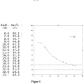
- a finite number of two-dimensional parameter sets can be calculated and stored, as in FIG Figure 1 shown, the boom length (or radius) is plotted on the abscissa and the maximum load capacity is plotted on the ordinate. From the drawn and precalculated limit curve z. B. read that the maximum load capacity for the boom length is 15 meters in about 30 tons.
- the limit curves for other functional elements or components of the superstructure are normally also two-dimensional and can be combined with the limit curves of the boom to form a two-dimensional set of parameters. So arise with z. B. a finite number n G of counterweights and n A boom lengths in total n A ⁇ n G two-dimensional parameter sets for the entire superstructure.
- Figure 2 shows the in Figure 1 Load curve already shown for the stability of the boom ALG, whereby the limit curves for the slewing ring DV, the luffing cylinder WZ and the superstructure OW (all shown by way of example over the radius of the boom) are also drawn in, which makes them comparable.
- the luffing cylinder curve can, for example, also be plotted over the luffing cylinder length. The connection between the length of the luffing cylinder and the radius can then be derived again from the condition of the crane.
- the lowest curve drawn as the load curve results, which, for. B. is determined up to a boom length of about 7 meters from the boom strength limit curve.
- the module load curve is determined by the limit curve of the slewing ring, since this allows lower values for the maximum load than the other limit curves in the range mentioned.
- the module load curve is defined by the luffing cylinder limit curve with the lowest permissible loads in this area.
- the limit curves for the components of the undercarriage can normally also be represented with a two-dimensional parameter set.
- the position of the uppercarriage relative to the undercarriage (angle of rotation) is excluded as a variable and a minimum value permissible for all positions is determined in advance.
- the superstructure parameter sets there are further possible combinations with the superstructure parameter sets. For example, with four support beams S1, S2, S3 and S4, there are n S1 ⁇ n S2 ⁇ n S3 ⁇ n S4 possible combinations with the superstructure parameter sets.
- a single parameter n S can exist in a large number of finite states or also in an infinite (stepless) number of states, so that a finite or infinite number of combinations results.
- the load capacity of a crane with at least two assemblies, each assembly being specified by at least one parameter, for example an operating parameter and / or a state parameter, is determined e.g. B. is determined by the fact that for at least a first assembly which has or has the lowest number of parameters or the lowest number of variation possibilities or the lowest gradient (the smallest change in the maximum load capacity when one or more status parameters change), the limit load or limit curve or the maximum payload is determined in advance and stored and the assigned value of the payload is read out for the current parameter or parameters, at least for a second module with the largest number of parameters or the largest number of possible variations or with the highest gradient (the greatest change in the maximum load when changing one or more status parameters) the limit load or maximum load is only determined if necessary.
- B. is determined by the fact that for at least a first assembly which has or has the lowest number of parameters or the lowest number of variation possibilities or the lowest gradient (the smallest change in the maximum load capacity when one or more status parameters change), the limit load or limit curve or the maximum payload is determined
- This needs-based determination is based on the current operating and / or state parameter combination and can e.g. B. by calculating and checking the calculation based on previously determined and stored values. For this, e.g. B. a formulaic relationship between the maximum load and the state parameters and / or operating parameters can be specified and stored as a calculation rule.
- a "first assembly" in the above sense can e.g. the superstructure including the boom and counterweight; a second assembly can e.g. Undercarriage with outriggers, uppercarriage and uppercarriage rotation angle.
- the determination of the load capacity or maximum load capacity of a crane is not only carried out exclusively on the basis of previously stored values.
- B. only used if it is easy to save limit curves, so z. B. two-dimensional limit curves or three-dimensional limit curves, in individual cases also one or more higher-dimensional limit curves and / or to check a calculation, z. B. for the undercarriage.
- z. B. two-dimensional limit curves or three-dimensional limit curves, in individual cases also one or more higher-dimensional limit curves and / or to check a calculation, z. B. for the undercarriage.
- the use of only low-dimensional limit curves according to the invention enables a simple partial solution to the problem of determining the overall load-bearing capacity of a crane.
- a calculation is carried out, which is based, for example, on one or more predefined formulaic relationships or formulas in order to use current parameter values or parameter combinations and taking account of the stored limit curves ascertained partial load capacities to determine a total load capacity, whereby, as already described, for safety reasons the lowest module-specific maximum load capacity is determined as the maximum load capacity of the crane.
- the assembly that can carry the lowest load in the present configuration determines the maximum permissible load of the crane.
- precalculated two- or three-dimensional limit curves or maximum module-related or module-specific loads for the boom system, and optionally also for the luffing cylinder, parameters that determine the current crane configuration can be read out and these precalculated limit curves or maximum module-related or module-specific load capacities can be transferred to the crane control become.
- the crane control z. B. on the basis of the detection of the current configuration of the boom system an assigned z. B. two-dimensional limit curve can be selected.
- the configuration of the boom system can e.g. B. can be recognized by entering a corresponding code or generally the corresponding configuration, for example by a user, and / or can also be recognized completely or additionally by one or more sensors.
- sensors can be arranged on a boom, which transmit the current length of the boom to the crane control.
- sensors can be arranged on a boom, which transmit the current length of the boom to the crane control.
- the relevant status and / or operating parameters are determined and based thereon the configuration or the parameters, for example, the two-dimensional limit curve for the superstructure is determined or from a memory be read out.
- the detection of the components or specific configuration can, as described above, by entering z. B. done by a user and / or by a sensor which is connected to the crane control or computing unit.
- the entry of parameters can also relate to the desired (later) states of the crane, which can currently have a different configuration. In this case, too, we speak of parameters that are actually present (eg entered).
- the maximum load capacity of the undercarriage can be determined on the basis of the detection of the configuration or of components, in particular the configuration or geometry of the support base of the undercarriage.
- the operating and / or status parameters used to describe the configuration of the undercarriage can e.g. B. entered and / or determined by sensors. Since the condition parameters of the undercarriage, e.g. four continuously and independently extendable and retractable support beams, in the example described not only can take on discretely predetermined values, but e.g. B. theoretically infinitely many values between two predetermined positions (z. B. fully retracted support beam and fully extended support beam) can assume due to a stepless adjustability and because several, z. B.
- the maximum load of the undercarriage is only calculated for the current configuration, whereby, unlike in the case of a pre-calculation and storage in a memory, it is not necessary to calculate and save all possible individual states or possible combinations of different individual states. This calculation can be checked using previously saved values.
- the calculated limit load or maximum payload can optionally also be determined taking into account the limit curve or payload determined as described above for the superstructure and boom system for a specific angle of rotation between the undercarriage and the superstructure.
- This calculation is optionally carried out for the entire turning range between undercarriage and uppercarriage, i.e. in the range from 0 degrees to 360 degrees, whereby this calculation can be carried out in advance or if necessary, for example also continuously, and can therefore specify a load curve dependent on the angle of rotation.
- this calculation can also be done in discrete steps and z. B. divided into continuous discrete steps, such as B. 1 degree increments or 5 degree increments, determine what the maximum load is for the rotational positions taken into account.
- a maximum load for any configuration of the support base and for any angle of rotation between the uppercarriage and undercarriage can be calculated based on a plurality of these calculations, e.g.
- a limit curve can be specified for the crane, and the maximum load for different angles of rotation of the superstructure relative to the undercarriage can be specified based on the individual calculations.
- the only variable parameter of this limit curve is then the angle of rotation, the undercarriage configuration is then assumed to be constant in the specific state.
- a new limit curve can also be calculated.
- B. the only parameter is the angle of rotation between the uppercarriage and the undercarriage. This makes it possible, on the one hand, to reduce the effort involved in the preliminary determination of limit curves and the storage required for the storage, and, on the other hand, to easily determine the total load-bearing capacity of a crane for a complete system with theoretically an infinite number of conditions or possible combinations, and thus to make optimum use of the total load-bearing capacity of the crane.
- the angle of rotation between undercarriage and superstructure can e.g. B. detected by a sensor and transmitted to the crane controller or a payload calculation unit to determine the maximum permissible payload for the currently available configuration.
- Figure 3 shows the working mode "360 degree table".
- the minimum load-bearing capacity from the entire turning range is taken as a basis. It is therefore not to be expected that a critical condition will arise during turning.
- the working speeds do not have to be limited separately.
- Figure 4 shows the work mode "Restricted work area".
- the work area is limited in advance to a certain area (e.g. 180 degrees to the rear).
- the minimum load capacity for the selected work area is taken as a basis.
- the switch-off limits for turning are known in advance and are independent of load capacity utilization. When approaching the work area limit, the speed is reduced in good time and the turning movement in front of or at the limit is stopped.
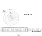
- Figure 5 shows the working mode "sector-related capacities".
- the work area is divided in advance into suitable sectors (e.g. 180 degrees left / right or 90 degrees above the supports).
- the minimum load-bearing capacity for the individual sectors is determined and taken as a basis.
- the switch-off limits for turning depend on the load capacity utilization and must be determined dynamically. A change in the permissible load can, however only come into play at the sector borders. Thus, the speed only has to be reduced separately when the sector boundaries are approached and the movement in front of or at the border may have to be stopped.
- Figure 6 shows the working mode "Optimized load capacity".
- the work area is divided into finite sectors (e.g. 5 degrees or 10 degrees) in advance.
- the optimum or maximum load-bearing capacity for this sector is used as a basis.
- the switch-off limits for turning depend on the load capacity utilization and are determined dynamically.
- the permissible load can be changed at any time. This means that the speed is constantly monitored and, depending on the permissible loads and the current utilization of the load capacity, can be adjusted separately and reduced if necessary. In the maximum case, the movement can be stopped in time.
- Figure 8 shows a crane which can carry out the method described above.
- a crane has a telescopic boom 1, the angle of attack of which can be adjusted by means of the luffing cylinder 2.
- support beams 3 are provided on the right and left, which can assume any intermediate position between a fully inserted position and a fully extended position.
- a counterweight 4 is provided, which can assume one of several predefined discrete values from different counterweights.
- Figure 9 shows the in Figure 8 Crane shown with the identification of sensors, which can be used individually or in combination to determine the configuration or state parameters or operating parameters of the crane.
- one or more sensors can be provided for determining the boom angle.
- a sensor can be provided for determining the boom length or boom telescoping.
- 9 designates the area in which a sensor for determining the luffing cylinder pressure and thus the operating state or the luffing cylinder configuration can be provided.
- One or more sensors for determining the support width can be provided at the points marked with 10 and sensors for determining the support pressure can be provided at the points marked with 11.
- a sensor for determining the counterweight denotes a sensor for determining the counterweight
- 13 a sensor for determining the rope force
- 14 a sensor for detecting additional equipment (for example a hose drum for supplying oil to the tip cylinder, a tip mounted on the boom).
- a sensor can optionally. B. can be provided to detect the actual load on the boom.
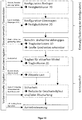
- Figure 10 shows a flow chart for calculating a payload volume.
- the configuration is first defined once, see the two steps above.
- the configuration of the boom and the configuration of the superstructure are determined and a strength curve or load curve is determined in each case, which can be two-dimensional or multi-dimensional.
- the state parameters of the boom are, for example, the angle, telescoping and tip (no conclusive list).
- the state parameters of the superstructure are, for example, the curve of the boom, the current counterweight and the state of the hoist (likewise no conclusive list).
- the undercarriage configuration can theoretically assume an infinite number of states due to the variable support width of the supports, whereby the load-bearing capacity is calculated for the specific condition, which is automatically determined, for example, using the sensors provided on the support supports to determine the respective extension state.
- a maximum load capacity dependent on the angle of rotation can be calculated.
- B. a three-dimensional payload volume can be created. Large gradients can also be recognized here. In this context, gradients can indicate, for example, how much the payload changes due to changes in parameters. These are very important for safe operation and can also be assessed separately.
- certain configurations e.g.
- the subsequent steps in operation can be carried out continuously or continuously. It can be used for the current angle of rotation between uppercarriage and undercarriage is determined, for example by means of a rotation angle sensor, the respectively permissible maximum load is determined. This then leads to the 2D payload curve load-over-radius, which represents the payload for different rocking angles (radii), for example.
- a calculation can be carried out to indicate to an operator that the speed is to be reduced or the crane is to be switched off in a safety mode.
- This information can also be automatically converted into the specified actions.
- the output value of a wind sensor and / or a support pressure limit and / or a user input can be taken into account.
- This information can be passed on to a drive control for operating the crane.
Landscapes
- Engineering & Computer Science (AREA)
- Mechanical Engineering (AREA)
- Physics & Mathematics (AREA)
- General Physics & Mathematics (AREA)
- Jib Cranes (AREA)
Applications Claiming Priority (1)
| Application Number | Priority Date | Filing Date | Title |
|---|---|---|---|
| DE102016104358.3A DE102016104358B4 (de) | 2016-03-10 | 2016-03-10 | Verfahren zum Ermitteln der Tragfähigkeit eines Krans sowie Kran |
Publications (2)
| Publication Number | Publication Date |
|---|---|
| EP3219662A1 EP3219662A1 (de) | 2017-09-20 |
| EP3219662B1 true EP3219662B1 (de) | 2020-04-15 |
Family
ID=58098472
Family Applications (1)
| Application Number | Title | Priority Date | Filing Date |
|---|---|---|---|
| EP17156459.4A Active EP3219662B1 (de) | 2016-03-10 | 2017-02-16 | Verfahren zum ermitteln der tragfähigkeit eines krans sowie kran |
Country Status (5)
| Country | Link |
|---|---|
| US (1) | US11161721B2 (https=) |
| EP (1) | EP3219662B1 (https=) |
| JP (1) | JP6518279B2 (https=) |
| CN (1) | CN107176543A (https=) |
| DE (1) | DE102016104358B4 (https=) |
Families Citing this family (11)
| Publication number | Priority date | Publication date | Assignee | Title |
|---|---|---|---|---|
| DE102016003566A1 (de) * | 2016-03-23 | 2017-09-28 | Liebherr-Werk Biberach Gmbh | Verfahren zur Überwachung einer Arbeitsmaschine |
| IT201800010918A1 (it) * | 2018-12-10 | 2020-06-10 | Manitou Italia Srl | Sistema di sicurezza perfezionato per macchine operatrici semoventi. |
| EP3722512B1 (de) | 2019-04-08 | 2022-06-08 | BAUER Maschinen GmbH | Tiefbaugerät und verfahren zum betreiben des tiefbaugeräts |
| US11511976B2 (en) * | 2019-10-07 | 2022-11-29 | Caterpillar Inc. | System and method for determining a lifting capacity of a machine |
| WO2021085569A1 (ja) * | 2019-10-29 | 2021-05-06 | 株式会社タダノ | 過負荷防止装置 |
| WO2021085566A1 (ja) * | 2019-10-29 | 2021-05-06 | 株式会社タダノ | 過負荷防止装置 |
| CN112723201B (zh) * | 2021-01-08 | 2022-03-04 | 中联重科股份有限公司 | 获取支撑位置的方法、装置及工程机械、可读存储介质 |
| DE102021102699A1 (de) | 2021-02-05 | 2022-08-11 | Liebherr-Werk Biberach Gmbh | Kran |
| AT17452U1 (de) * | 2021-02-23 | 2022-04-15 | Palfinger Ag | Verfahren zur Bestimmung einer Lagerreibung |
| FR3125031B1 (fr) * | 2021-07-08 | 2023-11-03 | Manitowoc Crane Group France | Procédé d’adaptation d’une courbe de charge d’une grue en fonction de sa configuration |
| EP4714889A1 (en) | 2024-09-19 | 2026-03-25 | Hiab AB | Crane arrangement including a pre-operation planning module |
Family Cites Families (55)
| Publication number | Priority date | Publication date | Assignee | Title |
|---|---|---|---|---|
| FR2390366A1 (fr) * | 1977-05-13 | 1978-12-08 | Preux Roger | Controleur d'etat de charge, notamment pour engin de levage |
| ATE185772T1 (de) * | 1988-12-27 | 1999-11-15 | Kato Seisakusho Kk | Kransicherheitsvorrichtung |
| US5730305A (en) * | 1988-12-27 | 1998-03-24 | Kato Works Co., Ltd. | Crane safety apparatus |
| US6744372B1 (en) * | 1997-02-27 | 2004-06-01 | Jack B. Shaw | Crane safety devices and methods |
| JP2000034093A (ja) * | 1998-07-21 | 2000-02-02 | Kobe Steel Ltd | 旋回式作業機械とその安全作業領域及び定格荷重の設定方法 |
| DE29924989U1 (de) * | 1999-07-07 | 2007-10-31 | Liebherr-Werk Ehingen Gmbh | Kontinuierlich verstellbarer Kran |
| DE10023418A1 (de) * | 2000-05-12 | 2001-11-15 | Liebherr Werk Nenzing | Verfahren zur Überlastsicherung eines mobilen Kranes |
| JP4173121B2 (ja) * | 2003-09-02 | 2008-10-29 | 株式会社小松製作所 | 建設機械の運転システム |
| DE102005035460A1 (de) * | 2005-07-28 | 2007-02-01 | Liebherr-Werk Ehingen Gmbh | Verfahren zur Traglastermittlung bei Kranen |
| US7599762B2 (en) * | 2005-08-24 | 2009-10-06 | Rockwell Automatino Technologies, Inc. | Model-based control for crane control and underway replenishment |
| US8065060B2 (en) * | 2006-01-18 | 2011-11-22 | The Board Of Regents Of The University And Community College System On Behalf Of The University Of Nevada | Coordinated joint motion control system with position error correction |
| JP5241079B2 (ja) * | 2006-04-28 | 2013-07-17 | 株式会社タダノ | 荷台を有する移動式クレーンの安定限界監視装置。 |
| DE102006027202A1 (de) * | 2006-06-12 | 2007-12-13 | Liebherr-Werk Nenzing Gmbh, Nenzing | Kraneinsatzplaner |
| DE202006017730U1 (de) * | 2006-11-21 | 2008-04-03 | Liebherr-Werk Ehingen Gmbh | Mobilkran |
| DE102008021627A1 (de) * | 2008-04-30 | 2009-11-12 | Liebherr-Werk Ehingen Gmbh | Mobilkran und Verfahren zum Betreiben eines Mobilkranes |
| CN101348216B (zh) * | 2008-09-05 | 2010-06-02 | 湖南三一起重机械有限公司 | 一种起重机安全保护系统及其起重机 |
| DE102009041661A1 (de) | 2009-09-16 | 2011-03-24 | Liebherr-Werk Nenzing Gmbh, Nenzing | System zur automatischen Erfassung von Lastzyklen einer Maschine zum Umschlagen von Lasten |
| US8352128B2 (en) * | 2009-09-25 | 2013-01-08 | TMEIC Corp. | Dynamic protective envelope for crane suspended loads |
| BRPI1001193A2 (pt) * | 2010-02-11 | 2012-07-03 | Vinicius De Carvalho Cal | aperfeiçoamento em grua e processo de controle de contrapeso em uma grua, em tempo real |
| CN101780927A (zh) | 2010-03-03 | 2010-07-21 | 淮阴工学院 | 汽车起重机倾翻预警装置 |
| DE102010025022A1 (de) * | 2010-06-24 | 2011-12-29 | Hirschmann Automation And Control Gmbh | Verfahren zur Lastmomentbegrenzung eines Arbeitsfahrzeuges mit einem Ausleger |
| DE202010014309U1 (de) | 2010-10-14 | 2012-01-18 | Liebherr-Werk Ehingen Gmbh | Kran, insbesondere Raupen- oder Mobilkran |
| US8527158B2 (en) * | 2010-11-18 | 2013-09-03 | Caterpillar Inc. | Control system for a machine |
| CN102464272A (zh) | 2010-11-18 | 2012-05-23 | 西安扩力机电科技有限公司 | 塔吊悬臂状态在线监控系统 |
| CN103781971B (zh) * | 2011-04-29 | 2016-05-04 | 哈尼施费格尔技术公司 | 控制工业机械的挖掘操作 |
| US8620536B2 (en) * | 2011-04-29 | 2013-12-31 | Harnischfeger Technologies, Inc. | Controlling a digging operation of an industrial machine |
| DE102011107754B4 (de) * | 2011-06-10 | 2021-07-22 | Liebherr-Werk Ehingen Gmbh | Winkelbezogenes Verfahren zur Überwachung der Kransicherheit während des Rüstvorgangs, sowie Kran und Kransteuerung |
| WO2013012761A2 (en) * | 2011-07-15 | 2013-01-24 | Bosco Eli | Enhanced stability crane and methods of use |
| DE102011108284A1 (de) * | 2011-07-21 | 2013-01-24 | Liebherr-Werk Ehingen Gmbh | Kransteuerung und Kran |
| FI20115922A0 (fi) * | 2011-09-20 | 2011-09-20 | Konecranes Oyj | Nosturin ohjaus |
| CN102514550B (zh) * | 2011-12-20 | 2014-04-30 | 长沙中联消防机械有限公司 | 工程机械以及其安全状态确定方法、装置和系统 |
| US9944500B2 (en) | 2012-02-17 | 2018-04-17 | Columbus Mckinnon Corporation | Material lifting system and method |
| EP2674384B1 (de) * | 2012-06-13 | 2021-01-27 | Liebherr-Werk Ehingen GmbH | Verfahren zur Überwachung der Kransicherheit sowie Kran |
| US9365398B2 (en) * | 2012-10-31 | 2016-06-14 | Manitowoc Crane Companies, Llc | Outrigger pad monitoring system |
| EP2954121B1 (en) * | 2013-02-06 | 2018-12-19 | Volvo Construction Equipment AB | Swing control system for construction machines |
| DE102013202413A1 (de) * | 2013-02-14 | 2014-08-14 | Siemens Aktiengesellschaft | Verfahren zum Kalibrieren eines beweglichen Kranteils eines Krans |
| US8977445B2 (en) * | 2013-06-18 | 2015-03-10 | Caterpillar Inc. | System and method for dig detection |
| JP5662597B1 (ja) * | 2013-08-30 | 2015-02-04 | 株式会社小松製作所 | 鉱山機械の管理システム及び鉱山機械の管理システムの管理方法 |
| CN104114826B (zh) * | 2014-02-26 | 2015-10-21 | 株式会社小松制作所 | 作业车辆 |
| DE102014105618A1 (de) * | 2014-04-22 | 2015-10-22 | Terex Cranes Germany Gmbh | Verfahren und Vorrichtung zum Betreiben eines Mobilkrans sowie Mobilkran |
| DE102015006992B4 (de) * | 2014-06-10 | 2021-04-15 | Liebherr-Werk Ehingen Gmbh | Verfahren und System zur Berechnung von Daten für den Betrieb eines Krans |
| JP6318949B2 (ja) * | 2014-07-29 | 2018-05-09 | コベルコ建機株式会社 | クレーン |
| US9529347B2 (en) * | 2014-08-28 | 2016-12-27 | Caterpillar Inc. | Operator assistance system for machine |
| DE202015001023U1 (de) * | 2015-02-09 | 2016-05-10 | Liebherr-Components Biberach Gmbh | Kran |
| DE202015001024U1 (de) * | 2015-02-09 | 2016-05-10 | Liebherr-Werk Biberach Gmbh | Kran mit Überwachungsvorrichtung zum Überwachen der Überlastsicherung |
| JP6314105B2 (ja) * | 2015-03-05 | 2018-04-18 | 株式会社日立製作所 | 軌道生成装置および作業機械 |
| US9783395B2 (en) * | 2015-03-31 | 2017-10-10 | Manitowoc Crane Companies, Llc | System and method for crane counterweight positioning |
| JP6412280B2 (ja) * | 2015-06-12 | 2018-10-24 | マニタウォック クレイン カンパニーズ, エルエルシーManitowoc Crane Companies, Llc | 中間カウンターウェイト位置での荷重表の計算のためのシステム及び方法 |
| US10065841B2 (en) * | 2016-01-26 | 2018-09-04 | Altec Industries, Inc. | Compact stowable luffing jib for a crane |
| JP7180966B2 (ja) * | 2016-01-29 | 2022-11-30 | マニタウォック クレイン カンパニーズ, エルエルシー | 視覚的アウトリガー監視システム |
| DE102016007723A1 (de) * | 2016-06-23 | 2017-12-28 | Liebherr-Werk Ehingen Gmbh | Lastwiegung am Lasthaken |
| US10676328B2 (en) * | 2016-08-24 | 2020-06-09 | Manitowoc Crane Companies, Llc | Crane function performance enhancement for non-symmetrical outrigger arrangements |
| DE102017001128B4 (de) * | 2017-02-07 | 2024-01-18 | Liebherr-Werk Ehingen Gmbh | Abstützung für einen Kran |
| JP6753795B2 (ja) * | 2017-02-14 | 2020-09-09 | 株式会社神戸製鋼所 | ウインチ制御装置及びクレーン |
| US11142438B2 (en) * | 2017-08-28 | 2021-10-12 | Manitowoc Crane Companies, Llc | Graphical working range diagrams for displaying allowable and projected loads |
-
2016
- 2016-03-10 DE DE102016104358.3A patent/DE102016104358B4/de active Active
-
2017
- 2017-02-16 EP EP17156459.4A patent/EP3219662B1/de active Active
- 2017-03-09 CN CN201710137806.9A patent/CN107176543A/zh active Pending
- 2017-03-09 US US15/454,641 patent/US11161721B2/en active Active
- 2017-03-09 JP JP2017044953A patent/JP6518279B2/ja active Active
Non-Patent Citations (1)
| Title |
|---|
| None * |
Also Published As
| Publication number | Publication date |
|---|---|
| DE102016104358B4 (de) | 2019-11-07 |
| US20170260029A1 (en) | 2017-09-14 |
| DE102016104358A1 (de) | 2017-09-14 |
| EP3219662A1 (de) | 2017-09-20 |
| JP6518279B2 (ja) | 2019-05-22 |
| JP2017206384A (ja) | 2017-11-24 |
| CN107176543A (zh) | 2017-09-19 |
| US11161721B2 (en) | 2021-11-02 |
Similar Documents
| Publication | Publication Date | Title |
|---|---|---|
| EP3219662B1 (de) | Verfahren zum ermitteln der tragfähigkeit eines krans sowie kran | |
| EP3134344B1 (de) | Verfahren und vorrichtung zum betreiben eines mobilkrans sowie mobilkran | |
| DE102011107754B4 (de) | Winkelbezogenes Verfahren zur Überwachung der Kransicherheit während des Rüstvorgangs, sowie Kran und Kransteuerung | |
| EP1444162B1 (de) | Fahrzeugkran mit superlifteinrichtung | |
| EP2674384B1 (de) | Verfahren zur Überwachung der Kransicherheit sowie Kran | |
| DE102011115224B4 (de) | Kran, insbesondere Raupen-oder Mobilkran | |
| DE102015006992B4 (de) | Verfahren und System zur Berechnung von Daten für den Betrieb eines Krans | |
| EP2135834B1 (de) | Kran, vorzugsweise Mobil- oder Raupenkran | |
| EP3470362B1 (de) | Verfahren und vorrichtung zur standsicherheitsüberwachung eines auf einem fahrzeug montierten ladekrans | |
| EP3856673B1 (de) | Kran sowie verfahren zum überwachen des betriebs eines solchen krans | |
| EP2113481A1 (de) | Mobilkran mit einer Kranüberwachungseinrichtung | |
| EP3428112B1 (de) | Hebezeug, insbesondere ein mobilkran oder ein seilbagger, mit einer vorrichtung zur überwachung des aufricht- und ablegevorganges eines auslegersystems und entsprechendes verfahren | |
| EP2524892A1 (de) | Kransteuerung | |
| DE102005059768A1 (de) | Kran, vorzugsweise Raupen- oder Fahrzeugkran | |
| DE19931302B4 (de) | Kontinuierlich verstellbarer Kran | |
| DE10233875B4 (de) | Krananlage, insbesondere Containerkran | |
| EP1925586B1 (de) | Mobilkran | |
| DE102012011726C5 (de) | Verfahren zum Betreiben eines Krans mit Überwachungseinheit sowie Kran | |
| EP1748021B1 (de) | Verfahren zur Traglastermittlung bei Kranen | |
| EP0672889A2 (de) | Verfahren zur Erfassung der Änderung des Radius eines Auslegers eines Kranes unter Last | |
| EP3546414B1 (de) | Verfahren zur ermittlung des gewichts einer von einer lademaschine aufgenommenen last und lademaschine hierfür | |
| DE102013000463A1 (de) | Mobiles Arbeitsgerät, insbesondere Mobilkran | |
| WO2014173609A1 (de) | Sensorbasierte überwachung von windrichtung und wärmeeinstrahlung für ein mobiles arbeitsgerät | |
| DE102021128317A1 (de) | Verfahren und System zur Planung eines Einsatzes zum Heben einer Last mit einem Kran | |
| EP4516718B1 (de) | Verfahren zur traglastüberwachung eines krans mit zwei lastaufnahmemitteln |
Legal Events
| Date | Code | Title | Description |
|---|---|---|---|
| PUAI | Public reference made under article 153(3) epc to a published international application that has entered the european phase |
Free format text: ORIGINAL CODE: 0009012 |
|
| STAA | Information on the status of an ep patent application or granted ep patent |
Free format text: STATUS: THE APPLICATION HAS BEEN PUBLISHED |
|
| AK | Designated contracting states |
Kind code of ref document: A1 Designated state(s): AL AT BE BG CH CY CZ DE DK EE ES FI FR GB GR HR HU IE IS IT LI LT LU LV MC MK MT NL NO PL PT RO RS SE SI SK SM TR |
|
| AX | Request for extension of the european patent |
Extension state: BA ME |
|
| STAA | Information on the status of an ep patent application or granted ep patent |
Free format text: STATUS: REQUEST FOR EXAMINATION WAS MADE |
|
| 17P | Request for examination filed |
Effective date: 20180129 |
|
| RBV | Designated contracting states (corrected) |
Designated state(s): AL AT BE BG CH CY CZ DE DK EE ES FI FR GB GR HR HU IE IS IT LI LT LU LV MC MK MT NL NO PL PT RO RS SE SI SK SM TR |
|
| RIC1 | Information provided on ipc code assigned before grant |
Ipc: B66C 23/90 20060101AFI20190923BHEP |
|
| GRAP | Despatch of communication of intention to grant a patent |
Free format text: ORIGINAL CODE: EPIDOSNIGR1 |
|
| STAA | Information on the status of an ep patent application or granted ep patent |
Free format text: STATUS: GRANT OF PATENT IS INTENDED |
|
| INTG | Intention to grant announced |
Effective date: 20191107 |
|
| GRAS | Grant fee paid |
Free format text: ORIGINAL CODE: EPIDOSNIGR3 |
|
| GRAA | (expected) grant |
Free format text: ORIGINAL CODE: 0009210 |
|
| STAA | Information on the status of an ep patent application or granted ep patent |
Free format text: STATUS: THE PATENT HAS BEEN GRANTED |
|
| AK | Designated contracting states |
Kind code of ref document: B1 Designated state(s): AL AT BE BG CH CY CZ DE DK EE ES FI FR GB GR HR HU IE IS IT LI LT LU LV MC MK MT NL NO PL PT RO RS SE SI SK SM TR |
|
| REG | Reference to a national code |
Ref country code: CH Ref legal event code: EP |
|
| REG | Reference to a national code |
Ref country code: DE Ref legal event code: R096 Ref document number: 502017004699 Country of ref document: DE |
|
| REG | Reference to a national code |
Ref country code: IE Ref legal event code: FG4D Free format text: LANGUAGE OF EP DOCUMENT: GERMAN |
|
| REG | Reference to a national code |
Ref country code: AT Ref legal event code: REF Ref document number: 1257061 Country of ref document: AT Kind code of ref document: T Effective date: 20200515 |
|
| REG | Reference to a national code |
Ref country code: NL Ref legal event code: MP Effective date: 20200415 |
|
| REG | Reference to a national code |
Ref country code: LT Ref legal event code: MG4D |
|
| PG25 | Lapsed in a contracting state [announced via postgrant information from national office to epo] |
Ref country code: NO Free format text: LAPSE BECAUSE OF FAILURE TO SUBMIT A TRANSLATION OF THE DESCRIPTION OR TO PAY THE FEE WITHIN THE PRESCRIBED TIME-LIMIT Effective date: 20200715 Ref country code: GR Free format text: LAPSE BECAUSE OF FAILURE TO SUBMIT A TRANSLATION OF THE DESCRIPTION OR TO PAY THE FEE WITHIN THE PRESCRIBED TIME-LIMIT Effective date: 20200716 Ref country code: SE Free format text: LAPSE BECAUSE OF FAILURE TO SUBMIT A TRANSLATION OF THE DESCRIPTION OR TO PAY THE FEE WITHIN THE PRESCRIBED TIME-LIMIT Effective date: 20200415 Ref country code: IS Free format text: LAPSE BECAUSE OF FAILURE TO SUBMIT A TRANSLATION OF THE DESCRIPTION OR TO PAY THE FEE WITHIN THE PRESCRIBED TIME-LIMIT Effective date: 20200815 Ref country code: FI Free format text: LAPSE BECAUSE OF FAILURE TO SUBMIT A TRANSLATION OF THE DESCRIPTION OR TO PAY THE FEE WITHIN THE PRESCRIBED TIME-LIMIT Effective date: 20200415 Ref country code: NL Free format text: LAPSE BECAUSE OF FAILURE TO SUBMIT A TRANSLATION OF THE DESCRIPTION OR TO PAY THE FEE WITHIN THE PRESCRIBED TIME-LIMIT Effective date: 20200415 Ref country code: LT Free format text: LAPSE BECAUSE OF FAILURE TO SUBMIT A TRANSLATION OF THE DESCRIPTION OR TO PAY THE FEE WITHIN THE PRESCRIBED TIME-LIMIT Effective date: 20200415 Ref country code: PT Free format text: LAPSE BECAUSE OF FAILURE TO SUBMIT A TRANSLATION OF THE DESCRIPTION OR TO PAY THE FEE WITHIN THE PRESCRIBED TIME-LIMIT Effective date: 20200817 |
|
| PG25 | Lapsed in a contracting state [announced via postgrant information from national office to epo] |
Ref country code: LV Free format text: LAPSE BECAUSE OF FAILURE TO SUBMIT A TRANSLATION OF THE DESCRIPTION OR TO PAY THE FEE WITHIN THE PRESCRIBED TIME-LIMIT Effective date: 20200415 Ref country code: RS Free format text: LAPSE BECAUSE OF FAILURE TO SUBMIT A TRANSLATION OF THE DESCRIPTION OR TO PAY THE FEE WITHIN THE PRESCRIBED TIME-LIMIT Effective date: 20200415 Ref country code: HR Free format text: LAPSE BECAUSE OF FAILURE TO SUBMIT A TRANSLATION OF THE DESCRIPTION OR TO PAY THE FEE WITHIN THE PRESCRIBED TIME-LIMIT Effective date: 20200415 Ref country code: BG Free format text: LAPSE BECAUSE OF FAILURE TO SUBMIT A TRANSLATION OF THE DESCRIPTION OR TO PAY THE FEE WITHIN THE PRESCRIBED TIME-LIMIT Effective date: 20200715 |
|
| PG25 | Lapsed in a contracting state [announced via postgrant information from national office to epo] |
Ref country code: AL Free format text: LAPSE BECAUSE OF FAILURE TO SUBMIT A TRANSLATION OF THE DESCRIPTION OR TO PAY THE FEE WITHIN THE PRESCRIBED TIME-LIMIT Effective date: 20200415 |
|
| REG | Reference to a national code |
Ref country code: DE Ref legal event code: R097 Ref document number: 502017004699 Country of ref document: DE |
|
| PG25 | Lapsed in a contracting state [announced via postgrant information from national office to epo] |
Ref country code: RO Free format text: LAPSE BECAUSE OF FAILURE TO SUBMIT A TRANSLATION OF THE DESCRIPTION OR TO PAY THE FEE WITHIN THE PRESCRIBED TIME-LIMIT Effective date: 20200415 Ref country code: CZ Free format text: LAPSE BECAUSE OF FAILURE TO SUBMIT A TRANSLATION OF THE DESCRIPTION OR TO PAY THE FEE WITHIN THE PRESCRIBED TIME-LIMIT Effective date: 20200415 Ref country code: ES Free format text: LAPSE BECAUSE OF FAILURE TO SUBMIT A TRANSLATION OF THE DESCRIPTION OR TO PAY THE FEE WITHIN THE PRESCRIBED TIME-LIMIT Effective date: 20200415 Ref country code: DK Free format text: LAPSE BECAUSE OF FAILURE TO SUBMIT A TRANSLATION OF THE DESCRIPTION OR TO PAY THE FEE WITHIN THE PRESCRIBED TIME-LIMIT Effective date: 20200415 Ref country code: SM Free format text: LAPSE BECAUSE OF FAILURE TO SUBMIT A TRANSLATION OF THE DESCRIPTION OR TO PAY THE FEE WITHIN THE PRESCRIBED TIME-LIMIT Effective date: 20200415 Ref country code: EE Free format text: LAPSE BECAUSE OF FAILURE TO SUBMIT A TRANSLATION OF THE DESCRIPTION OR TO PAY THE FEE WITHIN THE PRESCRIBED TIME-LIMIT Effective date: 20200415 |
|
| PLBE | No opposition filed within time limit |
Free format text: ORIGINAL CODE: 0009261 |
|
| STAA | Information on the status of an ep patent application or granted ep patent |
Free format text: STATUS: NO OPPOSITION FILED WITHIN TIME LIMIT |
|
| PG25 | Lapsed in a contracting state [announced via postgrant information from national office to epo] |
Ref country code: SK Free format text: LAPSE BECAUSE OF FAILURE TO SUBMIT A TRANSLATION OF THE DESCRIPTION OR TO PAY THE FEE WITHIN THE PRESCRIBED TIME-LIMIT Effective date: 20200415 Ref country code: PL Free format text: LAPSE BECAUSE OF FAILURE TO SUBMIT A TRANSLATION OF THE DESCRIPTION OR TO PAY THE FEE WITHIN THE PRESCRIBED TIME-LIMIT Effective date: 20200415 |
|
| 26N | No opposition filed |
Effective date: 20210118 |
|
| PG25 | Lapsed in a contracting state [announced via postgrant information from national office to epo] |
Ref country code: SI Free format text: LAPSE BECAUSE OF FAILURE TO SUBMIT A TRANSLATION OF THE DESCRIPTION OR TO PAY THE FEE WITHIN THE PRESCRIBED TIME-LIMIT Effective date: 20200415 |
|
| PG25 | Lapsed in a contracting state [announced via postgrant information from national office to epo] |
Ref country code: MC Free format text: LAPSE BECAUSE OF FAILURE TO SUBMIT A TRANSLATION OF THE DESCRIPTION OR TO PAY THE FEE WITHIN THE PRESCRIBED TIME-LIMIT Effective date: 20200415 |
|
| REG | Reference to a national code |
Ref country code: BE Ref legal event code: MM Effective date: 20210228 |
|
| PG25 | Lapsed in a contracting state [announced via postgrant information from national office to epo] |
Ref country code: LU Free format text: LAPSE BECAUSE OF NON-PAYMENT OF DUE FEES Effective date: 20210216 Ref country code: LI Free format text: LAPSE BECAUSE OF NON-PAYMENT OF DUE FEES Effective date: 20210228 Ref country code: CH Free format text: LAPSE BECAUSE OF NON-PAYMENT OF DUE FEES Effective date: 20210228 |
|
| PG25 | Lapsed in a contracting state [announced via postgrant information from national office to epo] |
Ref country code: IE Free format text: LAPSE BECAUSE OF NON-PAYMENT OF DUE FEES Effective date: 20210216 |
|
| PG25 | Lapsed in a contracting state [announced via postgrant information from national office to epo] |
Ref country code: BE Free format text: LAPSE BECAUSE OF NON-PAYMENT OF DUE FEES Effective date: 20210228 |
|
| PG25 | Lapsed in a contracting state [announced via postgrant information from national office to epo] |
Ref country code: IT Free format text: LAPSE BECAUSE OF NON-PAYMENT OF DUE FEES Effective date: 20210216 |
|
| REG | Reference to a national code |
Ref country code: AT Ref legal event code: MM01 Ref document number: 1257061 Country of ref document: AT Kind code of ref document: T Effective date: 20220216 |
|
| PG25 | Lapsed in a contracting state [announced via postgrant information from national office to epo] |
Ref country code: AT Free format text: LAPSE BECAUSE OF NON-PAYMENT OF DUE FEES Effective date: 20220216 |
|
| PG25 | Lapsed in a contracting state [announced via postgrant information from national office to epo] |
Ref country code: HU Free format text: LAPSE BECAUSE OF FAILURE TO SUBMIT A TRANSLATION OF THE DESCRIPTION OR TO PAY THE FEE WITHIN THE PRESCRIBED TIME-LIMIT; INVALID AB INITIO Effective date: 20170216 |
|
| P01 | Opt-out of the competence of the unified patent court (upc) registered |
Effective date: 20230515 |
|
| PG25 | Lapsed in a contracting state [announced via postgrant information from national office to epo] |
Ref country code: CY Free format text: LAPSE BECAUSE OF FAILURE TO SUBMIT A TRANSLATION OF THE DESCRIPTION OR TO PAY THE FEE WITHIN THE PRESCRIBED TIME-LIMIT Effective date: 20200415 |
|
| PG25 | Lapsed in a contracting state [announced via postgrant information from national office to epo] |
Ref country code: MK Free format text: LAPSE BECAUSE OF FAILURE TO SUBMIT A TRANSLATION OF THE DESCRIPTION OR TO PAY THE FEE WITHIN THE PRESCRIBED TIME-LIMIT Effective date: 20200415 |
|
| PG25 | Lapsed in a contracting state [announced via postgrant information from national office to epo] |
Ref country code: TR Free format text: LAPSE BECAUSE OF FAILURE TO SUBMIT A TRANSLATION OF THE DESCRIPTION OR TO PAY THE FEE WITHIN THE PRESCRIBED TIME-LIMIT Effective date: 20200415 |
|
| PG25 | Lapsed in a contracting state [announced via postgrant information from national office to epo] |
Ref country code: MT Free format text: LAPSE BECAUSE OF FAILURE TO SUBMIT A TRANSLATION OF THE DESCRIPTION OR TO PAY THE FEE WITHIN THE PRESCRIBED TIME-LIMIT Effective date: 20200415 |
|
| PGFP | Annual fee paid to national office [announced via postgrant information from national office to epo] |
Ref country code: GB Payment date: 20260219 Year of fee payment: 10 |
|
| PGFP | Annual fee paid to national office [announced via postgrant information from national office to epo] |
Ref country code: DE Payment date: 20260218 Year of fee payment: 10 |
|
| PGFP | Annual fee paid to national office [announced via postgrant information from national office to epo] |
Ref country code: FR Payment date: 20260218 Year of fee payment: 10 |