EP3218930B1 - Package for electronic system having semiconductor chips - Google Patents
Package for electronic system having semiconductor chips Download PDFInfo
- Publication number
- EP3218930B1 EP3218930B1 EP15859853.2A EP15859853A EP3218930B1 EP 3218930 B1 EP3218930 B1 EP 3218930B1 EP 15859853 A EP15859853 A EP 15859853A EP 3218930 B1 EP3218930 B1 EP 3218930B1
- Authority
- EP
- European Patent Office
- Prior art keywords
- chip
- terminals
- plane
- thickness
- slab
- Prior art date
- Legal status (The legal status is an assumption and is not a legal conclusion. Google has not performed a legal analysis and makes no representation as to the accuracy of the status listed.)
- Active
Links
Images


Classifications
-
- H—ELECTRICITY
- H01—ELECTRIC ELEMENTS
- H01L—SEMICONDUCTOR DEVICES NOT COVERED BY CLASS H10
- H01L25/00—Assemblies consisting of a plurality of semiconductor or other solid state devices
- H01L25/03—Assemblies consisting of a plurality of semiconductor or other solid state devices all the devices being of a type provided for in a single subclass of subclasses H10B, H10D, H10F, H10H, H10K or H10N, e.g. assemblies of rectifier diodes
- H01L25/04—Assemblies consisting of a plurality of semiconductor or other solid state devices all the devices being of a type provided for in a single subclass of subclasses H10B, H10D, H10F, H10H, H10K or H10N, e.g. assemblies of rectifier diodes the devices not having separate containers
- H01L25/065—Assemblies consisting of a plurality of semiconductor or other solid state devices all the devices being of a type provided for in a single subclass of subclasses H10B, H10D, H10F, H10H, H10K or H10N, e.g. assemblies of rectifier diodes the devices not having separate containers the devices being of a type provided for in group H10D89/00
- H01L25/0657—Stacked arrangements of devices
-
- H—ELECTRICITY
- H01—ELECTRIC ELEMENTS
- H01L—SEMICONDUCTOR DEVICES NOT COVERED BY CLASS H10
- H01L21/00—Processes or apparatus adapted for the manufacture or treatment of semiconductor or solid state devices or of parts thereof
- H01L21/02—Manufacture or treatment of semiconductor devices or of parts thereof
- H01L21/04—Manufacture or treatment of semiconductor devices or of parts thereof the devices having potential barriers, e.g. a PN junction, depletion layer or carrier concentration layer
- H01L21/50—Assembly of semiconductor devices using processes or apparatus not provided for in a single one of the groups H01L21/18 - H01L21/326 or H10D48/04 - H10D48/07 e.g. sealing of a cap to a base of a container
-
- H—ELECTRICITY
- H01—ELECTRIC ELEMENTS
- H01L—SEMICONDUCTOR DEVICES NOT COVERED BY CLASS H10
- H01L23/00—Details of semiconductor or other solid state devices
- H01L23/02—Containers; Seals
- H01L23/04—Containers; Seals characterised by the shape of the container or parts, e.g. caps, walls
- H01L23/053—Containers; Seals characterised by the shape of the container or parts, e.g. caps, walls the container being a hollow construction and having an insulating or insulated base as a mounting for the semiconductor body
-
- H—ELECTRICITY
- H01—ELECTRIC ELEMENTS
- H01L—SEMICONDUCTOR DEVICES NOT COVERED BY CLASS H10
- H01L23/00—Details of semiconductor or other solid state devices
- H01L23/02—Containers; Seals
- H01L23/06—Containers; Seals characterised by the material of the container or its electrical properties
-
- H—ELECTRICITY
- H01—ELECTRIC ELEMENTS
- H01L—SEMICONDUCTOR DEVICES NOT COVERED BY CLASS H10
- H01L23/00—Details of semiconductor or other solid state devices
- H01L23/12—Mountings, e.g. non-detachable insulating substrates
- H01L23/13—Mountings, e.g. non-detachable insulating substrates characterised by the shape
-
- H—ELECTRICITY
- H01—ELECTRIC ELEMENTS
- H01L—SEMICONDUCTOR DEVICES NOT COVERED BY CLASS H10
- H01L23/00—Details of semiconductor or other solid state devices
- H01L23/12—Mountings, e.g. non-detachable insulating substrates
- H01L23/14—Mountings, e.g. non-detachable insulating substrates characterised by the material or its electrical properties
- H01L23/147—Semiconductor insulating substrates
-
- H—ELECTRICITY
- H01—ELECTRIC ELEMENTS
- H01L—SEMICONDUCTOR DEVICES NOT COVERED BY CLASS H10
- H01L24/00—Arrangements for connecting or disconnecting semiconductor or solid-state bodies; Methods or apparatus related thereto
- H01L24/80—Methods for connecting semiconductor or other solid state bodies using means for bonding being attached to, or being formed on, the surface to be connected
- H01L24/83—Methods for connecting semiconductor or other solid state bodies using means for bonding being attached to, or being formed on, the surface to be connected using a layer connector
-
- H—ELECTRICITY
- H01—ELECTRIC ELEMENTS
- H01L—SEMICONDUCTOR DEVICES NOT COVERED BY CLASS H10
- H01L24/00—Arrangements for connecting or disconnecting semiconductor or solid-state bodies; Methods or apparatus related thereto
- H01L24/93—Batch processes
- H01L24/95—Batch processes at chip-level, i.e. with connecting carried out on a plurality of singulated devices, i.e. on diced chips
- H01L24/97—Batch processes at chip-level, i.e. with connecting carried out on a plurality of singulated devices, i.e. on diced chips the devices being connected to a common substrate, e.g. interposer, said common substrate being separable into individual assemblies after connecting
-
- H—ELECTRICITY
- H01—ELECTRIC ELEMENTS
- H01L—SEMICONDUCTOR DEVICES NOT COVERED BY CLASS H10
- H01L25/00—Assemblies consisting of a plurality of semiconductor or other solid state devices
- H01L25/03—Assemblies consisting of a plurality of semiconductor or other solid state devices all the devices being of a type provided for in a single subclass of subclasses H10B, H10D, H10F, H10H, H10K or H10N, e.g. assemblies of rectifier diodes
- H01L25/04—Assemblies consisting of a plurality of semiconductor or other solid state devices all the devices being of a type provided for in a single subclass of subclasses H10B, H10D, H10F, H10H, H10K or H10N, e.g. assemblies of rectifier diodes the devices not having separate containers
- H01L25/065—Assemblies consisting of a plurality of semiconductor or other solid state devices all the devices being of a type provided for in a single subclass of subclasses H10B, H10D, H10F, H10H, H10K or H10N, e.g. assemblies of rectifier diodes the devices not having separate containers the devices being of a type provided for in group H10D89/00
- H01L25/0652—Assemblies consisting of a plurality of semiconductor or other solid state devices all the devices being of a type provided for in a single subclass of subclasses H10B, H10D, H10F, H10H, H10K or H10N, e.g. assemblies of rectifier diodes the devices not having separate containers the devices being of a type provided for in group H10D89/00 the devices being arranged next and on each other, i.e. mixed assemblies
-
- H—ELECTRICITY
- H01—ELECTRIC ELEMENTS
- H01L—SEMICONDUCTOR DEVICES NOT COVERED BY CLASS H10
- H01L25/00—Assemblies consisting of a plurality of semiconductor or other solid state devices
- H01L25/03—Assemblies consisting of a plurality of semiconductor or other solid state devices all the devices being of a type provided for in a single subclass of subclasses H10B, H10D, H10F, H10H, H10K or H10N, e.g. assemblies of rectifier diodes
- H01L25/04—Assemblies consisting of a plurality of semiconductor or other solid state devices all the devices being of a type provided for in a single subclass of subclasses H10B, H10D, H10F, H10H, H10K or H10N, e.g. assemblies of rectifier diodes the devices not having separate containers
- H01L25/07—Assemblies consisting of a plurality of semiconductor or other solid state devices all the devices being of a type provided for in a single subclass of subclasses H10B, H10D, H10F, H10H, H10K or H10N, e.g. assemblies of rectifier diodes the devices not having separate containers the devices being of a type provided for in group subclass H10D
- H01L25/071—Assemblies consisting of a plurality of semiconductor or other solid state devices all the devices being of a type provided for in a single subclass of subclasses H10B, H10D, H10F, H10H, H10K or H10N, e.g. assemblies of rectifier diodes the devices not having separate containers the devices being of a type provided for in group subclass H10D the devices being arranged next and on each other, i.e. mixed assemblies
-
- H—ELECTRICITY
- H01—ELECTRIC ELEMENTS
- H01L—SEMICONDUCTOR DEVICES NOT COVERED BY CLASS H10
- H01L25/00—Assemblies consisting of a plurality of semiconductor or other solid state devices
- H01L25/03—Assemblies consisting of a plurality of semiconductor or other solid state devices all the devices being of a type provided for in a single subclass of subclasses H10B, H10D, H10F, H10H, H10K or H10N, e.g. assemblies of rectifier diodes
- H01L25/04—Assemblies consisting of a plurality of semiconductor or other solid state devices all the devices being of a type provided for in a single subclass of subclasses H10B, H10D, H10F, H10H, H10K or H10N, e.g. assemblies of rectifier diodes the devices not having separate containers
- H01L25/07—Assemblies consisting of a plurality of semiconductor or other solid state devices all the devices being of a type provided for in a single subclass of subclasses H10B, H10D, H10F, H10H, H10K or H10N, e.g. assemblies of rectifier diodes the devices not having separate containers the devices being of a type provided for in group subclass H10D
- H01L25/074—Stacked arrangements of non-apertured devices
-
- H—ELECTRICITY
- H01—ELECTRIC ELEMENTS
- H01L—SEMICONDUCTOR DEVICES NOT COVERED BY CLASS H10
- H01L25/00—Assemblies consisting of a plurality of semiconductor or other solid state devices
- H01L25/18—Assemblies consisting of a plurality of semiconductor or other solid state devices the devices being of the types provided for in two or more different main groups of the same subclass of H10B, H10D, H10F, H10H, H10K or H10N
-
- H—ELECTRICITY
- H01—ELECTRIC ELEMENTS
- H01L—SEMICONDUCTOR DEVICES NOT COVERED BY CLASS H10
- H01L25/00—Assemblies consisting of a plurality of semiconductor or other solid state devices
- H01L25/50—Multistep manufacturing processes of assemblies consisting of devices, the devices being individual devices of subclass H10D or integrated devices of class H10
-
- H—ELECTRICITY
- H10—SEMICONDUCTOR DEVICES; ELECTRIC SOLID-STATE DEVICES NOT OTHERWISE PROVIDED FOR
- H10D—INORGANIC ELECTRIC SEMICONDUCTOR DEVICES
- H10D62/00—Semiconductor bodies, or regions thereof, of devices having potential barriers
- H10D62/10—Shapes, relative sizes or dispositions of the regions of the semiconductor bodies; Shapes of the semiconductor bodies
- H10D62/117—Shapes of semiconductor bodies
-
- H—ELECTRICITY
- H01—ELECTRIC ELEMENTS
- H01L—SEMICONDUCTOR DEVICES NOT COVERED BY CLASS H10
- H01L2224/00—Indexing scheme for arrangements for connecting or disconnecting semiconductor or solid-state bodies and methods related thereto as covered by H01L24/00
- H01L2224/01—Means for bonding being attached to, or being formed on, the surface to be connected, e.g. chip-to-package, die-attach, "first-level" interconnects; Manufacturing methods related thereto
- H01L2224/02—Bonding areas; Manufacturing methods related thereto
- H01L2224/04—Structure, shape, material or disposition of the bonding areas prior to the connecting process
- H01L2224/06—Structure, shape, material or disposition of the bonding areas prior to the connecting process of a plurality of bonding areas
- H01L2224/061—Disposition
- H01L2224/0618—Disposition being disposed on at least two different sides of the body, e.g. dual array
- H01L2224/06181—On opposite sides of the body
-
- H—ELECTRICITY
- H01—ELECTRIC ELEMENTS
- H01L—SEMICONDUCTOR DEVICES NOT COVERED BY CLASS H10
- H01L2224/00—Indexing scheme for arrangements for connecting or disconnecting semiconductor or solid-state bodies and methods related thereto as covered by H01L24/00
- H01L2224/01—Means for bonding being attached to, or being formed on, the surface to be connected, e.g. chip-to-package, die-attach, "first-level" interconnects; Manufacturing methods related thereto
- H01L2224/26—Layer connectors, e.g. plate connectors, solder or adhesive layers; Manufacturing methods related thereto
- H01L2224/28—Structure, shape, material or disposition of the layer connectors prior to the connecting process
- H01L2224/29—Structure, shape, material or disposition of the layer connectors prior to the connecting process of an individual layer connector
- H01L2224/29001—Core members of the layer connector
- H01L2224/29099—Material
- H01L2224/2919—Material with a principal constituent of the material being a polymer, e.g. polyester, phenolic based polymer, epoxy
-
- H—ELECTRICITY
- H01—ELECTRIC ELEMENTS
- H01L—SEMICONDUCTOR DEVICES NOT COVERED BY CLASS H10
- H01L2224/00—Indexing scheme for arrangements for connecting or disconnecting semiconductor or solid-state bodies and methods related thereto as covered by H01L24/00
- H01L2224/01—Means for bonding being attached to, or being formed on, the surface to be connected, e.g. chip-to-package, die-attach, "first-level" interconnects; Manufacturing methods related thereto
- H01L2224/26—Layer connectors, e.g. plate connectors, solder or adhesive layers; Manufacturing methods related thereto
- H01L2224/31—Structure, shape, material or disposition of the layer connectors after the connecting process
- H01L2224/32—Structure, shape, material or disposition of the layer connectors after the connecting process of an individual layer connector
- H01L2224/321—Disposition
- H01L2224/32135—Disposition the layer connector connecting between different semiconductor or solid-state bodies, i.e. chip-to-chip
- H01L2224/32145—Disposition the layer connector connecting between different semiconductor or solid-state bodies, i.e. chip-to-chip the bodies being stacked
-
- H—ELECTRICITY
- H01—ELECTRIC ELEMENTS
- H01L—SEMICONDUCTOR DEVICES NOT COVERED BY CLASS H10
- H01L2224/00—Indexing scheme for arrangements for connecting or disconnecting semiconductor or solid-state bodies and methods related thereto as covered by H01L24/00
- H01L2224/80—Methods for connecting semiconductor or other solid state bodies using means for bonding being attached to, or being formed on, the surface to be connected
- H01L2224/83—Methods for connecting semiconductor or other solid state bodies using means for bonding being attached to, or being formed on, the surface to be connected using a layer connector
- H01L2224/838—Bonding techniques
- H01L2224/8385—Bonding techniques using a polymer adhesive, e.g. an adhesive based on silicone, epoxy, polyimide, polyester
- H01L2224/83851—Bonding techniques using a polymer adhesive, e.g. an adhesive based on silicone, epoxy, polyimide, polyester being an anisotropic conductive adhesive
-
- H—ELECTRICITY
- H01—ELECTRIC ELEMENTS
- H01L—SEMICONDUCTOR DEVICES NOT COVERED BY CLASS H10
- H01L2224/00—Indexing scheme for arrangements for connecting or disconnecting semiconductor or solid-state bodies and methods related thereto as covered by H01L24/00
- H01L2224/93—Batch processes
- H01L2224/94—Batch processes at wafer-level, i.e. with connecting carried out on a wafer comprising a plurality of undiced individual devices
-
- H—ELECTRICITY
- H01—ELECTRIC ELEMENTS
- H01L—SEMICONDUCTOR DEVICES NOT COVERED BY CLASS H10
- H01L2224/00—Indexing scheme for arrangements for connecting or disconnecting semiconductor or solid-state bodies and methods related thereto as covered by H01L24/00
- H01L2224/93—Batch processes
- H01L2224/95—Batch processes at chip-level, i.e. with connecting carried out on a plurality of singulated devices, i.e. on diced chips
- H01L2224/97—Batch processes at chip-level, i.e. with connecting carried out on a plurality of singulated devices, i.e. on diced chips the devices being connected to a common substrate, e.g. interposer, said common substrate being separable into individual assemblies after connecting
-
- H—ELECTRICITY
- H01—ELECTRIC ELEMENTS
- H01L—SEMICONDUCTOR DEVICES NOT COVERED BY CLASS H10
- H01L2225/00—Details relating to assemblies covered by the group H01L25/00 but not provided for in its subgroups
-
- H—ELECTRICITY
- H01—ELECTRIC ELEMENTS
- H01L—SEMICONDUCTOR DEVICES NOT COVERED BY CLASS H10
- H01L2225/00—Details relating to assemblies covered by the group H01L25/00 but not provided for in its subgroups
- H01L2225/03—All the devices being of a type provided for in the same main group of the same subclass of class H10, e.g. assemblies of rectifier diodes
- H01L2225/04—All the devices being of a type provided for in the same main group of the same subclass of class H10, e.g. assemblies of rectifier diodes the devices not having separate containers
- H01L2225/065—All the devices being of a type provided for in the same main group of the same subclass of class H10
- H01L2225/06503—Stacked arrangements of devices
- H01L2225/06513—Bump or bump-like direct electrical connections between devices, e.g. flip-chip connection, solder bumps
-
- H—ELECTRICITY
- H01—ELECTRIC ELEMENTS
- H01L—SEMICONDUCTOR DEVICES NOT COVERED BY CLASS H10
- H01L2225/00—Details relating to assemblies covered by the group H01L25/00 but not provided for in its subgroups
- H01L2225/03—All the devices being of a type provided for in the same main group of the same subclass of class H10, e.g. assemblies of rectifier diodes
- H01L2225/04—All the devices being of a type provided for in the same main group of the same subclass of class H10, e.g. assemblies of rectifier diodes the devices not having separate containers
- H01L2225/065—All the devices being of a type provided for in the same main group of the same subclass of class H10
- H01L2225/06503—Stacked arrangements of devices
- H01L2225/06517—Bump or bump-like direct electrical connections from device to substrate
-
- H—ELECTRICITY
- H01—ELECTRIC ELEMENTS
- H01L—SEMICONDUCTOR DEVICES NOT COVERED BY CLASS H10
- H01L2225/00—Details relating to assemblies covered by the group H01L25/00 but not provided for in its subgroups
- H01L2225/03—All the devices being of a type provided for in the same main group of the same subclass of class H10, e.g. assemblies of rectifier diodes
- H01L2225/04—All the devices being of a type provided for in the same main group of the same subclass of class H10, e.g. assemblies of rectifier diodes the devices not having separate containers
- H01L2225/065—All the devices being of a type provided for in the same main group of the same subclass of class H10
- H01L2225/06503—Stacked arrangements of devices
- H01L2225/06555—Geometry of the stack, e.g. form of the devices, geometry to facilitate stacking
-
- H—ELECTRICITY
- H01—ELECTRIC ELEMENTS
- H01L—SEMICONDUCTOR DEVICES NOT COVERED BY CLASS H10
- H01L2225/00—Details relating to assemblies covered by the group H01L25/00 but not provided for in its subgroups
- H01L2225/03—All the devices being of a type provided for in the same main group of the same subclass of class H10, e.g. assemblies of rectifier diodes
- H01L2225/04—All the devices being of a type provided for in the same main group of the same subclass of class H10, e.g. assemblies of rectifier diodes the devices not having separate containers
- H01L2225/065—All the devices being of a type provided for in the same main group of the same subclass of class H10
- H01L2225/06503—Stacked arrangements of devices
- H01L2225/06589—Thermal management, e.g. cooling
-
- H—ELECTRICITY
- H01—ELECTRIC ELEMENTS
- H01L—SEMICONDUCTOR DEVICES NOT COVERED BY CLASS H10
- H01L23/00—Details of semiconductor or other solid state devices
- H01L23/48—Arrangements for conducting electric current to or from the solid state body in operation, e.g. leads, terminal arrangements ; Selection of materials therefor
- H01L23/488—Arrangements for conducting electric current to or from the solid state body in operation, e.g. leads, terminal arrangements ; Selection of materials therefor consisting of soldered or bonded constructions
- H01L23/498—Leads, i.e. metallisations or lead-frames on insulating substrates, e.g. chip carriers
- H01L23/49838—Geometry or layout
- H01L23/49844—Geometry or layout for individual devices of subclass H10D
-
- H—ELECTRICITY
- H01—ELECTRIC ELEMENTS
- H01L—SEMICONDUCTOR DEVICES NOT COVERED BY CLASS H10
- H01L2924/00—Indexing scheme for arrangements or methods for connecting or disconnecting semiconductor or solid-state bodies as covered by H01L24/00
- H01L2924/01—Chemical elements
- H01L2924/01013—Aluminum [Al]
-
- H—ELECTRICITY
- H01—ELECTRIC ELEMENTS
- H01L—SEMICONDUCTOR DEVICES NOT COVERED BY CLASS H10
- H01L2924/00—Indexing scheme for arrangements or methods for connecting or disconnecting semiconductor or solid-state bodies as covered by H01L24/00
- H01L2924/01—Chemical elements
- H01L2924/01014—Silicon [Si]
-
- H—ELECTRICITY
- H01—ELECTRIC ELEMENTS
- H01L—SEMICONDUCTOR DEVICES NOT COVERED BY CLASS H10
- H01L2924/00—Indexing scheme for arrangements or methods for connecting or disconnecting semiconductor or solid-state bodies as covered by H01L24/00
- H01L2924/01—Chemical elements
- H01L2924/01022—Titanium [Ti]
-
- H—ELECTRICITY
- H01—ELECTRIC ELEMENTS
- H01L—SEMICONDUCTOR DEVICES NOT COVERED BY CLASS H10
- H01L2924/00—Indexing scheme for arrangements or methods for connecting or disconnecting semiconductor or solid-state bodies as covered by H01L24/00
- H01L2924/01—Chemical elements
- H01L2924/01028—Nickel [Ni]
-
- H—ELECTRICITY
- H01—ELECTRIC ELEMENTS
- H01L—SEMICONDUCTOR DEVICES NOT COVERED BY CLASS H10
- H01L2924/00—Indexing scheme for arrangements or methods for connecting or disconnecting semiconductor or solid-state bodies as covered by H01L24/00
- H01L2924/01—Chemical elements
- H01L2924/01079—Gold [Au]
-
- H—ELECTRICITY
- H01—ELECTRIC ELEMENTS
- H01L—SEMICONDUCTOR DEVICES NOT COVERED BY CLASS H10
- H01L2924/00—Indexing scheme for arrangements or methods for connecting or disconnecting semiconductor or solid-state bodies as covered by H01L24/00
- H01L2924/045—Carbides composed of metals from groups of the periodic table
- H01L2924/0464—14th Group
- H01L2924/04642—SiC
-
- H—ELECTRICITY
- H01—ELECTRIC ELEMENTS
- H01L—SEMICONDUCTOR DEVICES NOT COVERED BY CLASS H10
- H01L2924/00—Indexing scheme for arrangements or methods for connecting or disconnecting semiconductor or solid-state bodies as covered by H01L24/00
- H01L2924/049—Nitrides composed of metals from groups of the periodic table
- H01L2924/0494—4th Group
- H01L2924/04941—TiN
-
- H—ELECTRICITY
- H01—ELECTRIC ELEMENTS
- H01L—SEMICONDUCTOR DEVICES NOT COVERED BY CLASS H10
- H01L2924/00—Indexing scheme for arrangements or methods for connecting or disconnecting semiconductor or solid-state bodies as covered by H01L24/00
- H01L2924/049—Nitrides composed of metals from groups of the periodic table
- H01L2924/0504—14th Group
- H01L2924/05042—Si3N4
-
- H—ELECTRICITY
- H01—ELECTRIC ELEMENTS
- H01L—SEMICONDUCTOR DEVICES NOT COVERED BY CLASS H10
- H01L2924/00—Indexing scheme for arrangements or methods for connecting or disconnecting semiconductor or solid-state bodies as covered by H01L24/00
- H01L2924/053—Oxides composed of metals from groups of the periodic table
- H01L2924/0544—14th Group
- H01L2924/05442—SiO2
-
- H—ELECTRICITY
- H01—ELECTRIC ELEMENTS
- H01L—SEMICONDUCTOR DEVICES NOT COVERED BY CLASS H10
- H01L2924/00—Indexing scheme for arrangements or methods for connecting or disconnecting semiconductor or solid-state bodies as covered by H01L24/00
- H01L2924/10—Details of semiconductor or other solid state devices to be connected
- H01L2924/1015—Shape
- H01L2924/10155—Shape being other than a cuboid
-
- H—ELECTRICITY
- H01—ELECTRIC ELEMENTS
- H01L—SEMICONDUCTOR DEVICES NOT COVERED BY CLASS H10
- H01L2924/00—Indexing scheme for arrangements or methods for connecting or disconnecting semiconductor or solid-state bodies as covered by H01L24/00
- H01L2924/10—Details of semiconductor or other solid state devices to be connected
- H01L2924/102—Material of the semiconductor or solid state bodies
- H01L2924/1025—Semiconducting materials
- H01L2924/10251—Elemental semiconductors, i.e. Group IV
- H01L2924/10253—Silicon [Si]
-
- H—ELECTRICITY
- H01—ELECTRIC ELEMENTS
- H01L—SEMICONDUCTOR DEVICES NOT COVERED BY CLASS H10
- H01L2924/00—Indexing scheme for arrangements or methods for connecting or disconnecting semiconductor or solid-state bodies as covered by H01L24/00
- H01L2924/10—Details of semiconductor or other solid state devices to be connected
- H01L2924/102—Material of the semiconductor or solid state bodies
- H01L2924/1025—Semiconducting materials
- H01L2924/1026—Compound semiconductors
- H01L2924/1027—IV
- H01L2924/10271—Silicon-germanium [SiGe]
-
- H—ELECTRICITY
- H01—ELECTRIC ELEMENTS
- H01L—SEMICONDUCTOR DEVICES NOT COVERED BY CLASS H10
- H01L2924/00—Indexing scheme for arrangements or methods for connecting or disconnecting semiconductor or solid-state bodies as covered by H01L24/00
- H01L2924/10—Details of semiconductor or other solid state devices to be connected
- H01L2924/102—Material of the semiconductor or solid state bodies
- H01L2924/1025—Semiconducting materials
- H01L2924/1026—Compound semiconductors
- H01L2924/1032—III-V
- H01L2924/10329—Gallium arsenide [GaAs]
-
- H—ELECTRICITY
- H01—ELECTRIC ELEMENTS
- H01L—SEMICONDUCTOR DEVICES NOT COVERED BY CLASS H10
- H01L2924/00—Indexing scheme for arrangements or methods for connecting or disconnecting semiconductor or solid-state bodies as covered by H01L24/00
- H01L2924/10—Details of semiconductor or other solid state devices to be connected
- H01L2924/102—Material of the semiconductor or solid state bodies
- H01L2924/1025—Semiconducting materials
- H01L2924/1026—Compound semiconductors
- H01L2924/1032—III-V
- H01L2924/1033—Gallium nitride [GaN]
-
- H—ELECTRICITY
- H01—ELECTRIC ELEMENTS
- H01L—SEMICONDUCTOR DEVICES NOT COVERED BY CLASS H10
- H01L2924/00—Indexing scheme for arrangements or methods for connecting or disconnecting semiconductor or solid-state bodies as covered by H01L24/00
- H01L2924/10—Details of semiconductor or other solid state devices to be connected
- H01L2924/102—Material of the semiconductor or solid state bodies
- H01L2924/1025—Semiconducting materials
- H01L2924/1026—Compound semiconductors
- H01L2924/1037—II-VI
-
- H—ELECTRICITY
- H01—ELECTRIC ELEMENTS
- H01L—SEMICONDUCTOR DEVICES NOT COVERED BY CLASS H10
- H01L2924/00—Indexing scheme for arrangements or methods for connecting or disconnecting semiconductor or solid-state bodies as covered by H01L24/00
- H01L2924/10—Details of semiconductor or other solid state devices to be connected
- H01L2924/11—Device type
- H01L2924/13—Discrete devices, e.g. 3 terminal devices
- H01L2924/1301—Thyristor
-
- H—ELECTRICITY
- H01—ELECTRIC ELEMENTS
- H01L—SEMICONDUCTOR DEVICES NOT COVERED BY CLASS H10
- H01L2924/00—Indexing scheme for arrangements or methods for connecting or disconnecting semiconductor or solid-state bodies as covered by H01L24/00
- H01L2924/10—Details of semiconductor or other solid state devices to be connected
- H01L2924/11—Device type
- H01L2924/13—Discrete devices, e.g. 3 terminal devices
- H01L2924/1304—Transistor
- H01L2924/1305—Bipolar Junction Transistor [BJT]
- H01L2924/13055—Insulated gate bipolar transistor [IGBT]
-
- H—ELECTRICITY
- H01—ELECTRIC ELEMENTS
- H01L—SEMICONDUCTOR DEVICES NOT COVERED BY CLASS H10
- H01L2924/00—Indexing scheme for arrangements or methods for connecting or disconnecting semiconductor or solid-state bodies as covered by H01L24/00
- H01L2924/10—Details of semiconductor or other solid state devices to be connected
- H01L2924/11—Device type
- H01L2924/13—Discrete devices, e.g. 3 terminal devices
- H01L2924/1304—Transistor
- H01L2924/1306—Field-effect transistor [FET]
- H01L2924/13091—Metal-Oxide-Semiconductor Field-Effect Transistor [MOSFET]
-
- H—ELECTRICITY
- H01—ELECTRIC ELEMENTS
- H01L—SEMICONDUCTOR DEVICES NOT COVERED BY CLASS H10
- H01L2924/00—Indexing scheme for arrangements or methods for connecting or disconnecting semiconductor or solid-state bodies as covered by H01L24/00
- H01L2924/10—Details of semiconductor or other solid state devices to be connected
- H01L2924/11—Device type
- H01L2924/14—Integrated circuits
- H01L2924/141—Analog devices
- H01L2924/1425—Converter
-
- H—ELECTRICITY
- H01—ELECTRIC ELEMENTS
- H01L—SEMICONDUCTOR DEVICES NOT COVERED BY CLASS H10
- H01L2924/00—Indexing scheme for arrangements or methods for connecting or disconnecting semiconductor or solid-state bodies as covered by H01L24/00
- H01L2924/10—Details of semiconductor or other solid state devices to be connected
- H01L2924/11—Device type
- H01L2924/14—Integrated circuits
- H01L2924/141—Analog devices
- H01L2924/1427—Voltage regulator [VR]
-
- H—ELECTRICITY
- H01—ELECTRIC ELEMENTS
- H01L—SEMICONDUCTOR DEVICES NOT COVERED BY CLASS H10
- H01L2924/00—Indexing scheme for arrangements or methods for connecting or disconnecting semiconductor or solid-state bodies as covered by H01L24/00
- H01L2924/15—Details of package parts other than the semiconductor or other solid state devices to be connected
- H01L2924/151—Die mounting substrate
- H01L2924/1515—Shape
- H01L2924/15153—Shape the die mounting substrate comprising a recess for hosting the device
- H01L2924/15155—Shape the die mounting substrate comprising a recess for hosting the device the shape of the recess being other than a cuboid
- H01L2924/15156—Side view
-
- H—ELECTRICITY
- H01—ELECTRIC ELEMENTS
- H01L—SEMICONDUCTOR DEVICES NOT COVERED BY CLASS H10
- H01L2924/00—Indexing scheme for arrangements or methods for connecting or disconnecting semiconductor or solid-state bodies as covered by H01L24/00
- H01L2924/15—Details of package parts other than the semiconductor or other solid state devices to be connected
- H01L2924/151—Die mounting substrate
- H01L2924/156—Material
- H01L2924/157—Material with a principal constituent of the material being a metal or a metalloid, e.g. boron [B], silicon [Si], germanium [Ge], arsenic [As], antimony [Sb], tellurium [Te] and polonium [Po], and alloys thereof
Definitions
- This relates in general to semiconductor devices and processes, and more particularly to the structure and wafer-scale fabrication method of a low-grade silicon package for embedded semiconductor power block and half bridge devices.
- the semiconductor chip is typically assembled on a substrate (such as a metallic leadframe or a multi-level laminate), and encapsulated in a package of a robust material (such as ceramic or hardened plastic compound).
- the assembly process typically includes the process of attaching the chip to a substrate pad or the leadframe pad, and the process of connecting the chip terminals to substrate leads using bonding wires or solder balls.
- CMOS complementary metal-oxide-semiconductor
- CMOS complementary metal-oxide-semiconductor
- the assembly is referred to as power stage or, more commonly, as synchronous buck converter.
- the control FET chip also called the high-side switch
- the synchronous (sync) FET chip also called the low side switch
- the gates of the control FET chip and the sync FET chip are connected to a semiconductor chip including the circuitry for the driver of the converter and the controller; the chip is also connected to ground potential.
- the chips of the power MOSFETs and the chip of the driver and controller IC are assembled horizontally side-by-side as individual components. Each chip is typically attached to a rectangular or square-shaped pad of a metallic leadframe, and the pad is surrounded by leads as output terminals.
- the power MOSFET chips and the driver-and-controller IC are assembled horizontally side-by-side on a single leadframe pad, which in turn is surrounded on all four sides by leads serving as device output terminals.
- the leads are commonly shaped without cantilever extensions, and arranged in the manner of quad flat no-lead (QFN) or small outline no-lead (SON) devices.
- the electrical connections from the chips to the leads may be provided by bonding wires, whose lengths and resistances introduce significant parasitic inductance into the power circuit.
- clips substitute for many connecting wires. These clips are wide and introduce minimum parasitic inductance, but are more expensive than wire bonds and require a more involved assembly process.
- Each assembly is typically packaged in a plastic encapsulation, and the packaged components are employed as discrete building blocks for board assembly of power supply systems.
- control FET chip and the sync FET chip are assembled vertically on top of each other as a stack, with the physically larger-area chip (among those two) being attached to the leadframe pad, and with clips providing the connections to the switch node and the stack top.
- the sync FET chip needs a larger active area than the active area of the control FET chip, due to considerations of duty cycle and conduction loss.
- the larger (both physically and active area) sync chip is assembled onto the leadframe pad and the smaller (both physically and active area) control chip has its source tied to the drain of the sync chip, forming the switch node, and its drain to the input supply V IN ; a clip is connected to the switch node between the two chips.
- the pad is at ground potential and serves as a spreader of operationally generated heat; the elongated clip of the stack top is tied to input supply V IN .
- EP1501126 A1 discloses a packaged electronic system comprising two nested semiconductor chips, wherein one chip is accommodated in a recessed portion of the other.
- US2012/146177 A1 discloses a packaged electronic system comprising power semiconductor chips disposed in a recessed area of a slab of substrate material.
- US2012/104623 A1 discloses in the context of power conversion a packaged electronic system, wherein stacked semiconductor chips are disposed in a recessed area of a slab of semiconductor substrate material.
- US2014/273344 A1 discloses a packaged electronic system comprising a stack of two power semiconductor chips forming a power converter, wherein each chip has terminals on both of its main surfaces and the chip terminals are connected to a planar leadframe via clips.
- an electronic system includes a first chip of single-crystalline semiconductor, including a first electronic device embedded in a second chip of single-crystalline semiconductor shaped as a container having a slab bordered by ridges, and including a second electronic device.
- the nested chips are assembled in a container of low-grade silicon shaped as a slab bordered by retaining walls and including conductive traces and terminals.
- the first electronic device is connected to the second electronic device by attaching the first chip onto the slab of the second chip.
- the first and second electronic devices are connected to the container by embedding the second chip in the container.
- the nested first and second chips operate as an electronic system, and the container operates as the package of the system.
- the system is a power block.
- Example embodiments significantly improve semiconductor transistor devices, power blocks and power converters with respect to reducing parasitic resistances and inductances, improving thermal performances and speed, enhancing operational reliability in moist and temperature-variable ambient, and reducing manufacturing cost.
- the conventional composite package where semiconductor chips are assembled on a metallic carrier and packaged in a plastic encapsulation, combines materials of widely different coefficients of thermal expansion, leading to a propensity for thermo-mechanical stresses, and requires a lengthy, time-consuming and costly fabrication flow.
- the materials and cost problems of a semiconductor package are solved by a structure concept and manufacturing flow for packages, which adopts and parallels the mass production and controlled processes of routine semiconductor wafer manufacturing.
- the new package is based on using silicon slabs cut from wafers made of low-grade and thus low cost silicon, such as those obtained from reclaimed, unrefined and undoped silicon. While processed in wafer form, a slab obtains a depression suitable for assembling a single-crystal device chip, and it can act as a carrier as well as the final package.
- the new package concept eliminates leadframes, bonding wires, metallic clips, solder balls, and plastic, ceramic and metallic housings. Instead, the fabrication processes use proven front-end techniques, such as etching semiconductors, metals and insulators, depositing layers of metals, insulators and passivation, growing insulating layers, and patterning by photoresist technologies.
- the assembly problem is solved by a concept and manufacturing flow for chips with completed transistors or circuits, which includes the etching of depressions into the completed chips having contours and depth for embedding smaller chips into the depression.
- the resulting devices do not suffer from mismatched coefficients of thermal expansion, but instead allow the minimization of thermo-mechanical stresses. Also, parasitic resistances and inductances are reduced because wire bonds and clips are eliminated. Thermal conductivity (and thus electrical performance) of the new devices is enhanced by attaching the chips of the finished devices directly onto circuit boards. Also, the resulting power blocks and power converters (with stacked and embedded chips) allow concurrent device miniaturization in x-dimension, y-dimension and z-dimension.
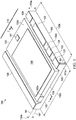
- FIG. 1 illustrates system 100 as an example embodiment that includes a power block 110 embedded into, and attached to, a container of low-grade silicon (1-g-Si) including a slab 130 and ridges, or retaining walls 131.
- the container exhibits certain terminals of the system and also operates as the system package.
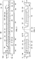
- FIG. 2 shows a cross section through power block 101 along lines 2-2. The cross section illustrates the attachments of the transistor chips and the layer sequence of metals and insulators.
- FIG. 3 depicts a cross section through multiple packaged systems after completing the assembly, yet before sawing the wafer of low-grade silicon into discrete packaged systems.
- slab 130 has a flat surface 135 and is made of low-grade silicon (1-g-Si), which is selected from a group including (but not limited to) reclaimed silicon, unrefined silicon, undoped silicon, polycrystalline silicon, intrinsic polycrystalline silicon, lowly doped n-type polycrystalline silicon and lowly doped p-type polycrystalline silicon.
- the 1-g-Si material may be heavily doped to obtain low resistivity.
- slab 130 has a thickness 130a of ⁇ 300 ⁇ m, a length 130b of ⁇ 5.8 mm, and a width 130c of ⁇ 3.7 mm. Thickness 130a is herein referred to as first thickness.
- the material of the 1-g-Si slab is exposed at the edges 131a of the slab.
- the slab top proper viewed in FIG. 1 , is made of a first insulating layer 133, which determines first plane 191. Portions of the insulating layer are exposed at certain locations, while other portions are covered by a metal layer, which is configured as terminals 120 (e.g., switch node of the power block), terminal 121 (e.g., gate of the high side FET) and terminal 122 (e.g., drain of the high side FET tied to input supply V IN ) of system 100.
- the insulating surface of the slab is called herein first surface 130d, which is in a first plane 191.
- slab 130 is configured as a set of elevated ridges 131 with the top surface 130d in plane 191, so that the ridges are framing a depression.
- the system has two parallel ridges. In other embodiments, the system may have more ridges.
- the depression includes a recessed central area with a surface 134 in a second plane 192. Surface 134 is covered by a second insulating layer 136.
- the central area is suitable to accommodate at least semiconductor chip 102.
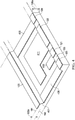
- FIG. 8 Another embodiment is shown in FIG. 8 , where the central area is suitable to accommodate more than one chip.
- first depth 132a is equal to the sum of the chip thickness 102a and the thickness of the adhesive material used for attaching chip 102 to the recessed central area.
- first depth 132a may be ⁇ 64 ⁇ m.
- the central area is covered by a patterned metal layer configured as attachment pads for the device terminals, such as transistor terminals. As FIGS. 2 and 3 show, the pads of the central area are grouped into an inner set and a peripheral set.
- chip 102 is made of heavily doped single-crystalline silicon, which allows direct contact to a metal layer, often referred to as back metal.
- the doped silicon is topped by an epitaxial layer of intrinsic silicon, which includes a drain-down MOS field effect transistor (FET) serving as the low side transistor of the power block and is herein referred to as the second semiconductor chip.
- FET drain-down MOS field effect transistor
- Chip 102 has a thickness 102a, such as -50 ⁇ m, which is herein referred to as third thickness.
- Third thickness 102a is smaller than first thickness 130a, but greater than second thickness 101a (which is depicted in FIGS. 2 and 3 as the thickness of the first semiconductor chip 101).
- Chip 102 has a flat side 102d ( FIG. 1 ), which is referred to herein as the third side.
- the example MOS FET of FIG. 1 has its source terminal 140 and gate terminal 141 on the third side facing away from slab 130.
- Source terminal 140 is electrically tied to ground potential.
- the semiconductor chip may be made of silicon-germanium, gallium arsenide, gallium nitride, or other III-V and II-VI compounds used as semiconductor device materials.
- the drain terminal may be facing away from the slab.
- the transistor may be a bipolar transistor having the collector contact facing away from the slab; or the bipolar transistor may have the emitter terminal facing away from the slab.
- FIG. 2 shows a cross section of system 100 along lines 2-2 in FIG. 1 , the ridges of slab 130 are not represented. Instead, FIG. 2 shows the flat surface 135 of the slab and the flat surface 134 of the recessed central area, which is in the second plane 192.
- FIG. 2 further displays a first semiconductor chip 101 and a second semiconductor chip 102, which may be larger than fist chip 101. Both chips are made of a single-crystalline semiconductor material, such as silicon.
- FIG. 2 indicates flat side 102d, which is referred to herein as third side.
- FIG. 2 further illustrates that chip 102 has a fourth side 102b, which is contoured.
- fourth side 102b is configured as a set of ridges 103 with a surface in third plane 193; ridges 103 frame a depression.
- chip 102 has two parallel ridges. In other embodiments, chip 102 may have more ridges.
- the depression includes a recessed flat central area with a surface 102c in a fourth plane 194 parallel to plane 193. The central area is suitable to accommodate first chip 101, which is thus embedded in second chip 102.
- FIG. 1 illustrates that fourth plane 194 is spaced from the third plane 193 by a second depth 132b smaller than the first depth 132a and suitable to accommodate the thickness of first chip 101 with its metal layers and layers of attachment material.
- FIG. 2 indicates that fourth side 102b including surface 102c of chip 102 is uniformly covered by a metal layer 221, which is sometimes referred to as back metal.
- layer 221 includes a layer of refractory metal (such as titanium or tungsten) for adhesion to the semiconductor crystal, followed by a layer of nickel and an outermost layer of a noble metal (such as silver, palladium or gold). In some products, the refractory metal layer is omitted.
- Portions of the third side 102d of chip 102 also have a sequence of stacked layers of similar metal selections, such as titanium, nickel and silver, or just nickel and gold. The stacked metal layers are patterned into pads 222 and 223.
- chip 102 includes a field effect transistor (FET), which serves as the low-side FET of the power block.
- FET field effect transistor
- the bulk single-crystal silicon of chip 102 is heavily doped and makes good contact to the so-called back metal layer 221.
- the metallized fourth chip side 102b with metal layer 221 serves as the drain terminal of the low-side FET, electrically tied to the switch node, pad 222 is the source terminal electrically tied to ground potential, and pad 223 the gate terminal of the low-side FET.
- the fourth chip side 102b of chip 102 includes the ridges and the central area, which is depressed relative to the ridges.
- first chip 101 is embedded in the depression of second chip 102.
- first chip 101 is made of a single-crystalline semiconductor material, such as silicon.
- both first side 101d and second side 101b of first chip 101 are flat.
- First chip 101 has thickness 101a, which is smaller than second depth 132b, so that first chip 101 (together with its metal layers and attachment layers) can be embedded in the depressed central area of second chip 102.
- chip 101 includes a field effect transistor (FET), which serves as the high-side FET of the power block and has terminals on the first and the second chip side.
- FET field effect transistor
- the metal pad 211 of first chip side 101d serves as the drain terminal of the high-side FET, electrically tied to the input supply V IN
- pad 213 is the gate terminal of the high-side FET.
- the 1-g-Si material of slab 130 is covered by an insulating layer 136, preferably thermally grown silicon dioxide.
- the insulating layer has increased thickness, which is a secondary effect of the patterning of the metal layer, discussed by the process flow below.
- insulating layer 136 is covered by a metal layer.
- One metal layer may be sufficient, but FIG. 2 illustrates a preferred method of a sequence of metal layers.
- the first layer 231 is made of a refractory metal such as titanium, followed by a compound layer such as titanium nitride. Alternative choices include a layer of tungsten, titanium-tungsten or another refractory metal. The refractory metal adheres strongly to insulating layer 136.
- a layer 232 of aluminum is deposited onto the refractory metal layer; layer 232 is preferably thicker than layer 231.
- layer 232 is preferably thicker than layer 231.
- the metal layers 231 and 232 are patterned in the depressed central area of slab 130.
- the result of the patterning is multiple pads grouped into an inner set and a peripheral set.
- the pads of the inner set match the terminals of the transistors of the first chip 101, and the pads of the peripheral set match the terminals of the ridges of second chip 102.
- the patterned metal pads of the inner set include the drain terminal 241 and the gate terminal 243 of the high-side FET.
- the patterned metal pads of the peripheral set include the switch node terminals 242 of the power block, which combines the source terminal of the high-side FET and the drain terminal of the low-side FET.
- FIG. 3 depicts a portion of a 1-g-Si wafer 330 with multiple slab sites after completing the assembly of first and second FET chips in each slab site.
- the assembly encompasses a first chip 101 embedded in the depression of a second chip 102 and, in turn, the second chip embedded in the depression of a respective slab.
- Second chip 102 is formed as a container including a slab 104 bordered by ridges 103.
- the embedded positions imply that the metallized depressed central area of the fourth side of second chip 102 is attached to the terminals on the second side of the first chip, and the metallized ridges of the second chip is attached to the pads of the peripheral set of the central 1-g-Si area, so the transistor terminals on the third side of the second chip are co-planar with the metal layer on the ridges of the respective 1-g-Si slab.
- the plane of co-planarity is designated 191; it is referred to herein as first plane.
- FIG. 3 the cut lines through the wafer for separating the slab sites are marked 340.
- a discrete system looks as system 100 depicted in FIG. 1 .
- Metal layer 222 (as the source terminal 140) and metal layer 223 (as the gate terminal 141) are ready for attachment to external parts, when system 100 is connected to a circuit board.
- Another embodiment is a method of fabricating semiconductor slabs bordered by retaining walls suitable as device packages, and a method of fabricating a packaged electronic system using a silicon slab as a package for semiconductor devices.
- Certain processes are summarized in FIGS. 4 , 5A , 5B , 6 and 7 .
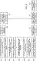
- An overview of the process flow for fabricating an electronic system with stacked chips embedded in a silicon package is presented in the flow chart of FIG. 9 .
- the process flow of fabricating semiconductor slabs starts with providing a wafer of low-grade silicon (1-g-Si), which includes multiple slab sites (process 901).
- the wafer has two parallel flat surfaces, one of which is referred to as first surface.
- the preferred wafer diameter is 300 mm, but smaller diameters may be used; the plane of the first surface is referred to as first plane 191.
- the final wafer (before dicing) has a thickness 130a (referred to as first thickness) of ⁇ 300 ⁇ m. Nevertheless, the preceding process steps may be executed using a thicker wafer and obtaining the final thickness by back-grinding. Consequently, designation 110a of FIG. 3 intends to indicate such wafer thickness greater than 130a.
- the 1-g-Si may be selected from a group including reclaimed silicon, unrefined silicon, undoped silicon, polycrystalline silicon and intrinsic polycrystalline silicon.
- the 1-g-Si material may also include lowly doped n-type polycrystalline silicon and lowly doped p-type polycrystalline silicon.
- the 1-g-Si material may also include low resistivity n-type polycrystalline silicon and low resistivity p-type polycrystalline silicon.
- a first insulating layer 133 is formed on the first surface of the wafer (process 902); the layer covers all slab sites.
- the preferred technique of forming an insulating surface layer is thermally oxidizing the silicon.
- Alternative techniques include depositing a layer of silicon dioxide, silicon nitride, silicon carbide, or a combination thereof, and depositing an insulating compound different from a silicon compound.
- the first insulating layer is removed from the central portion of each slab site to expose the underlying 1-g-Si, while leaving unremoved the first insulating layer 133 over the peripheral site portions to form ridges framing each central portion (process 903).
- the ridges are sometimes referred to as retaining walls or rims bordering the central portion.
- FIG. 4 depicts an individual slab site at a processing state, which summarizes the results of the above-referenced fabrication processes; the depicted site is an integral portion of a larger wafer, as indicated by the phantom lines.
- the depression has a rectangular configuration bordered by two parallel ridges.
- the depression which is formed by the etching process, also creates a step of 1-g-Si between the first plane 191 and the second plane 192.
- the step is inclined less than 90°. More preferably, the step forms a gradual slope 401 between the first and the second 1-g-Si surface, so that an uninterrupted metal layer can easily be deposited on slope 401.
- the flow starts by providing a wafer of undoped or weakly doped 1-g-Si, which includes multiple slab sites 210. Each site is configured into ridges with a top in a first plane 290 and a depression framed by the ridges. The depression includes a recessed central area in a second plane 291, spaced from the first plane by a depth 112.
- a second insulating layer 136 is formed on the second silicon surface; layer 136 covers all slab sites (process 905). Other techniques are possible, but preferably the second insulating layer is thermally grown, so that the silicon dioxide of the second layer 136 merges with the left-over silicon dioxide of the first layer 133.
- At least one layer 231 of metal is deposited onto the second insulating layer 136, covering all slab sites (process 906).
- a layer of a refractory metal such as titanium is selected, followed by a compound layer such as titanium nitride.
- Alternative choices include a layer of tungsten, titanium-tungsten or another refractory metal.
- the refractory metal adheres strongly to insulating layer 136.
- a layer 232 of aluminum is deposited onto the refractory metal layer.
- Layer 232 is preferably thicker than layer 231.
- FIG. 4 gives an overview of the patterned metal pads of a discrete slab.
- system terminals are formed on the ridges.
- pads for transistor terminals are created, which are grouped in an inner set and a peripheral set.
- metal layers 120 are destined to be system terminals for the switch node of a power block; metal layer 121 will be the terminal for the gate of the high-side FET; and layer 122 will be system terminal of the drain of the high-side FET tied to the input supply V IN of the system.
- the result of the patterning is multiple pads grouped in an inner and a peripheral set, matching the terminals of transistors.
- the pads of the inner set include pad 411 for the drain terminal 211 of the high-side FET (ending as terminal 122 on the ridge) and pad 413 for the gate terminal 213 of the high-side FET (ending as terminal 121 on the ridge).
- the pads of the peripheral set include pads 420 for the switch node terminal (ending as terminals 120 on the ridges).
- a layer 205 of passivation material such as silicon nitride is deposited onto the patterned metal layer, covering all slab sites (process 908).
- Passivation layer 237 is then removed, at each slab site, from the terminals on the ridges and from the pads in the central portion to expose the underlying metal. By comparison, the passivation material over the slopes and between the pads is left unremoved.
- first semiconductor chips 101 have a flat first side 101b and an opposite flat second side 101d, and a second thickness 101a smaller than the first thickness 130a of the 1-g-Si slab.
- the first chips may include transistors with terminals on the first and the second chip side.
- the chips are shaped as a hexahedron and made of single-crystalline silicon.
- the chips include a FET with a source terminal on the first chip side and a drain terminal 211 and a gate terminal 213 on the opposite second chip side.
- chip 101 may include a bipolar transistor, or it may have different terminal distribution, or chip 101 may be made of gallium arsenide, gallium nitride or any other semiconductor single crystalline compound.
- FIG. 5B depicts an example slab site after the attachment, which creates sub-assemblies designated 500 in FIG. 5B .
- the terminals 212 of the second side of the first chip face towards the first plane 191.
- terminal 212 represents the source terminal of the FET of the first chip.
- second semiconductor chips 102 have a flat third side 102d and an opposite contoured fourth side 102b, and a third thickness 102a smaller than the first thickness but greater than the second thickness 101a.
- the fourth side 102b is configured as a ridge, or retaining wall, in a third plane 193 framing a depression including a flat central area in a parallel fourth plane 194 recessed from the third plane by a second depth 132b.
- Second depth 132b is configured to be smaller than the first depth 132a of a slab, and suitable to accommodate a first chip 101.
- Second chips 102 are made of a single crystalline semiconductor, frequently silicon, which is heavily doped and makes good contact to the uniform metal layer covering the fourth side 102b. Also, chips 102 include an epitaxial layer suitable for forming active devices, such as FETs or bipolar transistors. In the example of FIG. 6 , the transistor is a FET with a source terminal 222 and a gate terminal 223 on the third side 102d, and a drain terminal on the fourth side 102b.
- FIG. 7 illustrates the assembly of a second chip 102 with a subassembly 500 of FIG. 5B (process 912).
- the metallized depressed central area of the fourth side 102b of a second chip 102 is attached to the terminals on the second side 101b of the respective first chip 101, and the metallized ridges of the second chip 102 are attached to the pads of the respective peripheral set of the central 1-g-Si area.
- the transistor terminals 222 and 223 on the third side 102d of the second chips become co-planar with the terminals 120, 121 and 122 on the ridges of the respective 1-g-Si slab 130.
- All attachment processes are preferably performed using a conductive paste of an adhesive polymeric compound; alternatively, they may be performed using a lead-free solder.
- the co-planarity of all system terminals facilitates the assembly of the system onto external boards.
- the 1-g-Si wafer is cut by saws or laser into singulated systems, as depicted in FIG. 1 (process 913).
- the electronic system with stacked semiconductor chips embedded in a silicon package offers numerous technical advantages. Compared to conventional systems, multiple parts are eliminated, all of which are costly, labor-intensive in manufacturing, and parasitic in electrical parameters, such as: bonding wires, connecting clips, metallic leadframes, plastic molding compounds, and solders with lead. Thermal performance is greatly improved by low theta parameters to case, to top, to ambient, and heat sinks.
- the ratio of active silicon versus package is high, and the overall system thickness can be kept very thin ( ⁇ 0.3 to ⁇ 0.5 mm). Differences between the coefficients of thermal expansion of chips and package are minimized or eliminated; thermo-mechanical stresses are thus minimized.
- FIG. 8 Other embodiments are electronic systems, such as a DC-DC power converter, often referred to as synchronous Buck converter.
- the example converter depicted in FIG. 8 includes a vertical stack of two FET chips, embedded into each other, and an adjacent driver-and-controller chip assembled on a 1-g-Si container formed as a slab with retaining walls.
- the example system has a length 801 of 5.0 mm, a width 802 of 3.0 mm, and a height 803 of 0.45 mm. All metal terminals and the silicon back side 810a of the driver-and-controller chip 810 are co-planar; the common plane is designated 191.
- metal layer 222 is the source terminal of the low-side FET (sync FET)
- layer 223 is the gate terminal of the low-side FET (sync FET)
- metal layer 122 is the drain terminal of the high-side FET, electrically tied to the input supply V IN
- layer 121 is the gate terminal of the high-side FET
- layers 120 are the terminals of the switch node
- metal layers 811, 812, 813, 814, 815 and 816 are the output pins of the integrated driver-and-controller circuit of flipped chip 810.
- the exposed silicon surface 810a may be metallized to facilitate the attachment to an external board.
- example embodiments apply to field effect transistors, and also to other suitable power transistors, bipolar transistors, insulated gate transistors, thyristors and others.
- the above considerations for structure and fabrication method of power converters apply to regulators, multi-output power converters, applications with sensing terminals, and applications with Kelvin terminals and others.
- the high current capability of the packaged transistors and converter can be further extended, and the efficiency further enhanced, by using the blank backside of the 1-g-Si, after attachment of the devices to a board, so that the back side can be connected to a heat sink, preferably.
- the device can dissipate its heat into the board and into the heat sink.
Landscapes
- Engineering & Computer Science (AREA)
- Microelectronics & Electronic Packaging (AREA)
- Power Engineering (AREA)
- Computer Hardware Design (AREA)
- Physics & Mathematics (AREA)
- Condensed Matter Physics & Semiconductors (AREA)
- General Physics & Mathematics (AREA)
- Manufacturing & Machinery (AREA)
- Metal-Oxide And Bipolar Metal-Oxide Semiconductor Integrated Circuits (AREA)
Applications Claiming Priority (2)
| Application Number | Priority Date | Filing Date | Title |
|---|---|---|---|
| US14/537,943 US9305852B1 (en) | 2014-11-11 | 2014-11-11 | Silicon package for embedded electronic system having stacked semiconductor chips |
| PCT/US2015/060208 WO2016077488A1 (en) | 2014-11-11 | 2015-11-11 | Package for electronic system having semiconductor chips |
Publications (3)
| Publication Number | Publication Date |
|---|---|
| EP3218930A1 EP3218930A1 (en) | 2017-09-20 |
| EP3218930A4 EP3218930A4 (en) | 2018-07-25 |
| EP3218930B1 true EP3218930B1 (en) | 2020-05-27 |
Family
ID=55589080
Family Applications (1)
| Application Number | Title | Priority Date | Filing Date |
|---|---|---|---|
| EP15859853.2A Active EP3218930B1 (en) | 2014-11-11 | 2015-11-11 | Package for electronic system having semiconductor chips |
Country Status (5)
| Country | Link |
|---|---|
| US (2) | US9305852B1 (enExample) |
| EP (1) | EP3218930B1 (enExample) |
| JP (1) | JP6709785B2 (enExample) |
| CN (1) | CN107078124B (enExample) |
| WO (1) | WO2016077488A1 (enExample) |
Families Citing this family (8)
| Publication number | Priority date | Publication date | Assignee | Title |
|---|---|---|---|---|
| US9893058B2 (en) * | 2015-09-17 | 2018-02-13 | Semiconductor Components Industries, Llc | Method of manufacturing a semiconductor device having reduced on-state resistance and structure |
| EP3279935B1 (en) * | 2016-08-02 | 2019-01-02 | ABB Schweiz AG | Power semiconductor module |
| US20200235067A1 (en) * | 2019-01-22 | 2020-07-23 | Texas Instruments Incorporated | Electronic device flip chip package with exposed clip |
| US11031321B2 (en) * | 2019-03-15 | 2021-06-08 | Infineon Technologies Ag | Semiconductor device having a die pad with a dam-like configuration |
| US11024564B2 (en) | 2019-06-19 | 2021-06-01 | Texas Instruments Incorporated | Packaged electronic device with film isolated power stack |
| EP3944304A1 (en) * | 2020-07-20 | 2022-01-26 | Nexperia B.V. | A semiconductor device and a method of manufacture |
| CN114899171B (zh) * | 2022-04-29 | 2025-10-03 | 佛山市国星光电股份有限公司 | 一种无焊线功率器件 |
| CN115188853A (zh) * | 2022-08-15 | 2022-10-14 | 西安西热产品认证检测有限公司 | 一种低温双面光伏组件 |
Family Cites Families (16)
| Publication number | Priority date | Publication date | Assignee | Title |
|---|---|---|---|---|
| US4568958A (en) * | 1984-01-03 | 1986-02-04 | General Electric Company | Inversion-mode insulated-gate gallium arsenide field-effect transistors |
| JP4052078B2 (ja) * | 2002-10-04 | 2008-02-27 | 富士通株式会社 | 半導体装置 |
| EP1501126A1 (en) * | 2003-11-05 | 2005-01-26 | Infineon Technologies AG | Semiconductor chip having a cavity for stacked die application |
| US7279786B2 (en) * | 2005-02-04 | 2007-10-09 | Stats Chippac Ltd. | Nested integrated circuit package on package system |
| US9147649B2 (en) * | 2008-01-24 | 2015-09-29 | Infineon Technologies Ag | Multi-chip module |
| US8358014B2 (en) * | 2009-05-28 | 2013-01-22 | Texas Instruments Incorporated | Structure and method for power field effect transistor |
| WO2012021310A1 (en) * | 2010-08-09 | 2012-02-16 | Rambus Inc. | Disaggregated semiconductor chip assembly and packaging technique |
| US8666505B2 (en) * | 2010-10-26 | 2014-03-04 | Medtronic, Inc. | Wafer-scale package including power source |
| US9337116B2 (en) * | 2010-10-28 | 2016-05-10 | Stats Chippac, Ltd. | Semiconductor device and method of forming stepped interposer for stacking and electrically connecting semiconductor die |
| US8994048B2 (en) * | 2010-12-09 | 2015-03-31 | Stats Chippac, Ltd. | Semiconductor device and method of forming recesses in substrate for same size or different sized die with vertical integration |
| CN102169872B (zh) * | 2011-01-26 | 2013-07-03 | 上海腾怡半导体有限公司 | 集成电感的电源模块 |
| GB2492551A (en) * | 2011-07-04 | 2013-01-09 | Accuric Ltd | Current regulator |
| US9589929B2 (en) * | 2013-03-14 | 2017-03-07 | Vishay-Siliconix | Method for fabricating stack die package |
| JP2014209091A (ja) * | 2013-03-25 | 2014-11-06 | ローム株式会社 | 半導体装置 |
| TWI518844B (zh) * | 2013-12-11 | 2016-01-21 | 矽品精密工業股份有限公司 | 封裝結構及其製法 |
| CN105575913B (zh) * | 2016-02-23 | 2019-02-01 | 华天科技(昆山)电子有限公司 | 埋入硅基板扇出型3d封装结构 |
-
2014
- 2014-11-11 US US14/537,943 patent/US9305852B1/en active Active
-
2015
- 2015-11-11 CN CN201580059417.8A patent/CN107078124B/zh active Active
- 2015-11-11 WO PCT/US2015/060208 patent/WO2016077488A1/en not_active Ceased
- 2015-11-11 EP EP15859853.2A patent/EP3218930B1/en active Active
- 2015-11-11 JP JP2017525537A patent/JP6709785B2/ja active Active
-
2016
- 2016-02-25 US US15/053,089 patent/US10109614B2/en active Active
Non-Patent Citations (1)
| Title |
|---|
| None * |
Also Published As
| Publication number | Publication date |
|---|---|
| CN107078124B (zh) | 2020-11-06 |
| WO2016077488A1 (en) | 2016-05-19 |
| EP3218930A1 (en) | 2017-09-20 |
| CN107078124A (zh) | 2017-08-18 |
| US20160172338A1 (en) | 2016-06-16 |
| EP3218930A4 (en) | 2018-07-25 |
| US10109614B2 (en) | 2018-10-23 |
| JP6709785B2 (ja) | 2020-06-17 |
| JP2017535960A (ja) | 2017-11-30 |
| US9305852B1 (en) | 2016-04-05 |
Similar Documents
| Publication | Publication Date | Title |
|---|---|---|
| EP3218930B1 (en) | Package for electronic system having semiconductor chips | |
| EP3005417B1 (en) | Integrating multi-output power converters having vertically stacked semiconductor chips | |
| US11177246B2 (en) | Photo-sensitive silicon package embedding self-powered electronic system | |
| CN105981170B (zh) | 具有半导体芯片端子的dc-dc转换器 | |
| US11574855B2 (en) | Package with dies mounted on opposing surfaces of a leadframe | |
| CN103426837B (zh) | 半导体封装及形成半导体封装的方法 | |
| US10062624B2 (en) | Silicon package for embedded semiconductor chip and power converter | |
| US11043477B2 (en) | Power converter monolithically integrating transistors, carrier, and components | |
| EP2521171A1 (en) | High voltage cascoded III-nitride rectifier package with stamped leadframe | |
| EP3143642B1 (en) | Gang clips having distributed-function tie bars | |
| US10153220B2 (en) | Silicon package having electrical functionality by embedded passive components |
Legal Events
| Date | Code | Title | Description |
|---|---|---|---|
| STAA | Information on the status of an ep patent application or granted ep patent |
Free format text: STATUS: THE INTERNATIONAL PUBLICATION HAS BEEN MADE |
|
| PUAI | Public reference made under article 153(3) epc to a published international application that has entered the european phase |
Free format text: ORIGINAL CODE: 0009012 |
|
| STAA | Information on the status of an ep patent application or granted ep patent |
Free format text: STATUS: REQUEST FOR EXAMINATION WAS MADE |
|
| 17P | Request for examination filed |
Effective date: 20170612 |
|
| AK | Designated contracting states |
Kind code of ref document: A1 Designated state(s): AL AT BE BG CH CY CZ DE DK EE ES FI FR GB GR HR HU IE IS IT LI LT LU LV MC MK MT NL NO PL PT RO RS SE SI SK SM TR |
|
| AX | Request for extension of the european patent |
Extension state: BA ME |
|
| DAV | Request for validation of the european patent (deleted) | ||
| DAX | Request for extension of the european patent (deleted) | ||
| RIC1 | Information provided on ipc code assigned before grant |
Ipc: H01L 25/07 20060101ALI20180613BHEP Ipc: H01L 23/14 20060101ALI20180613BHEP Ipc: H01L 25/03 20060101ALI20180613BHEP Ipc: H01L 23/02 20060101ALI20180613BHEP Ipc: H01L 25/065 20060101AFI20180613BHEP Ipc: H01L 29/06 20060101ALI20180613BHEP |
|
| A4 | Supplementary search report drawn up and despatched |
Effective date: 20180621 |
|
| REG | Reference to a national code |
Ref country code: DE Ref legal event code: R079 Ref document number: 602015053562 Country of ref document: DE Free format text: PREVIOUS MAIN CLASS: H01L0025030000 Ipc: H01L0023053000 |
|
| RIC1 | Information provided on ipc code assigned before grant |
Ipc: H01L 25/065 20060101ALI20191031BHEP Ipc: H01L 23/00 20060101ALI20191031BHEP Ipc: H01L 23/053 20060101AFI20191031BHEP Ipc: H01L 23/14 20060101ALI20191031BHEP Ipc: H01L 25/03 20060101ALI20191031BHEP Ipc: H01L 23/02 20060101ALI20191031BHEP Ipc: H01L 23/06 20060101ALI20191031BHEP Ipc: H01L 23/13 20060101ALI20191031BHEP Ipc: H01L 25/00 20060101ALI20191031BHEP Ipc: H01L 21/50 20060101ALI20191031BHEP Ipc: H01L 25/07 20060101ALI20191031BHEP Ipc: H01L 23/498 20060101ALN20191031BHEP Ipc: H01L 29/06 20060101ALI20191031BHEP Ipc: H01L 25/18 20060101ALI20191031BHEP |
|
| RIC1 | Information provided on ipc code assigned before grant |
Ipc: H01L 21/98 20060101ALI20191105BHEP Ipc: H01L 25/065 20060101ALI20191105BHEP Ipc: H01L 23/498 20060101ALN20191105BHEP Ipc: H01L 23/13 20060101ALI20191105BHEP Ipc: H01L 25/07 20060101ALI20191105BHEP Ipc: H01L 23/06 20060101ALI20191105BHEP Ipc: H01L 23/053 20060101AFI20191105BHEP Ipc: H01L 29/06 20060101ALI20191105BHEP Ipc: H01L 25/18 20060101ALI20191105BHEP Ipc: H01L 21/50 20060101ALI20191105BHEP Ipc: H01L 23/14 20060101ALI20191105BHEP |
|
| GRAP | Despatch of communication of intention to grant a patent |
Free format text: ORIGINAL CODE: EPIDOSNIGR1 |
|
| STAA | Information on the status of an ep patent application or granted ep patent |
Free format text: STATUS: GRANT OF PATENT IS INTENDED |
|
| RIC1 | Information provided on ipc code assigned before grant |
Ipc: H01L 29/06 20060101ALI20191126BHEP Ipc: H01L 25/18 20060101ALI20191126BHEP Ipc: H01L 21/50 20060101ALI20191126BHEP Ipc: H01L 23/053 20060101AFI20191126BHEP Ipc: H01L 25/065 20060101ALI20191126BHEP Ipc: H01L 23/06 20060101ALI20191126BHEP Ipc: H01L 23/13 20060101ALI20191126BHEP Ipc: H01L 23/498 20060101ALN20191126BHEP Ipc: H01L 25/07 20060101ALI20191126BHEP Ipc: H01L 21/98 20060101ALI20191126BHEP Ipc: H01L 23/14 20060101ALI20191126BHEP |
|
| INTG | Intention to grant announced |
Effective date: 20191213 |
|
| RAP1 | Party data changed (applicant data changed or rights of an application transferred) |
Owner name: TEXAS INSTRUMENTS INCORPORATED |
|
| GRAS | Grant fee paid |
Free format text: ORIGINAL CODE: EPIDOSNIGR3 |
|
| GRAA | (expected) grant |
Free format text: ORIGINAL CODE: 0009210 |
|
| STAA | Information on the status of an ep patent application or granted ep patent |
Free format text: STATUS: THE PATENT HAS BEEN GRANTED |
|
| AK | Designated contracting states |
Kind code of ref document: B1 Designated state(s): AL AT BE BG CH CY CZ DE DK EE ES FI FR GB GR HR HU IE IS IT LI LT LU LV MC MK MT NL NO PL PT RO RS SE SI SK SM TR |
|
| REG | Reference to a national code |
Ref country code: GB Ref legal event code: FG4D |
|
| REG | Reference to a national code |
Ref country code: CH Ref legal event code: EP |
|
| REG | Reference to a national code |
Ref country code: AT Ref legal event code: REF Ref document number: 1275453 Country of ref document: AT Kind code of ref document: T Effective date: 20200615 |
|
| REG | Reference to a national code |
Ref country code: DE Ref legal event code: R096 Ref document number: 602015053562 Country of ref document: DE |
|
| REG | Reference to a national code |
Ref country code: LT Ref legal event code: MG4D |
|
| PG25 | Lapsed in a contracting state [announced via postgrant information from national office to epo] |
Ref country code: IS Free format text: LAPSE BECAUSE OF FAILURE TO SUBMIT A TRANSLATION OF THE DESCRIPTION OR TO PAY THE FEE WITHIN THE PRESCRIBED TIME-LIMIT Effective date: 20200927 Ref country code: PT Free format text: LAPSE BECAUSE OF FAILURE TO SUBMIT A TRANSLATION OF THE DESCRIPTION OR TO PAY THE FEE WITHIN THE PRESCRIBED TIME-LIMIT Effective date: 20200928 Ref country code: NO Free format text: LAPSE BECAUSE OF FAILURE TO SUBMIT A TRANSLATION OF THE DESCRIPTION OR TO PAY THE FEE WITHIN THE PRESCRIBED TIME-LIMIT Effective date: 20200827 Ref country code: GR Free format text: LAPSE BECAUSE OF FAILURE TO SUBMIT A TRANSLATION OF THE DESCRIPTION OR TO PAY THE FEE WITHIN THE PRESCRIBED TIME-LIMIT Effective date: 20200828 Ref country code: LT Free format text: LAPSE BECAUSE OF FAILURE TO SUBMIT A TRANSLATION OF THE DESCRIPTION OR TO PAY THE FEE WITHIN THE PRESCRIBED TIME-LIMIT Effective date: 20200527 Ref country code: SE Free format text: LAPSE BECAUSE OF FAILURE TO SUBMIT A TRANSLATION OF THE DESCRIPTION OR TO PAY THE FEE WITHIN THE PRESCRIBED TIME-LIMIT Effective date: 20200527 Ref country code: FI Free format text: LAPSE BECAUSE OF FAILURE TO SUBMIT A TRANSLATION OF THE DESCRIPTION OR TO PAY THE FEE WITHIN THE PRESCRIBED TIME-LIMIT Effective date: 20200527 |
|
| REG | Reference to a national code |
Ref country code: NL Ref legal event code: MP Effective date: 20200527 |
|
| PG25 | Lapsed in a contracting state [announced via postgrant information from national office to epo] |
Ref country code: BG Free format text: LAPSE BECAUSE OF FAILURE TO SUBMIT A TRANSLATION OF THE DESCRIPTION OR TO PAY THE FEE WITHIN THE PRESCRIBED TIME-LIMIT Effective date: 20200827 Ref country code: HR Free format text: LAPSE BECAUSE OF FAILURE TO SUBMIT A TRANSLATION OF THE DESCRIPTION OR TO PAY THE FEE WITHIN THE PRESCRIBED TIME-LIMIT Effective date: 20200527 Ref country code: LV Free format text: LAPSE BECAUSE OF FAILURE TO SUBMIT A TRANSLATION OF THE DESCRIPTION OR TO PAY THE FEE WITHIN THE PRESCRIBED TIME-LIMIT Effective date: 20200527 Ref country code: RS Free format text: LAPSE BECAUSE OF FAILURE TO SUBMIT A TRANSLATION OF THE DESCRIPTION OR TO PAY THE FEE WITHIN THE PRESCRIBED TIME-LIMIT Effective date: 20200527 |
|
| REG | Reference to a national code |
Ref country code: AT Ref legal event code: MK05 Ref document number: 1275453 Country of ref document: AT Kind code of ref document: T Effective date: 20200527 |
|
| PG25 | Lapsed in a contracting state [announced via postgrant information from national office to epo] |
Ref country code: AL Free format text: LAPSE BECAUSE OF FAILURE TO SUBMIT A TRANSLATION OF THE DESCRIPTION OR TO PAY THE FEE WITHIN THE PRESCRIBED TIME-LIMIT Effective date: 20200527 Ref country code: NL Free format text: LAPSE BECAUSE OF FAILURE TO SUBMIT A TRANSLATION OF THE DESCRIPTION OR TO PAY THE FEE WITHIN THE PRESCRIBED TIME-LIMIT Effective date: 20200527 |
|
| PG25 | Lapsed in a contracting state [announced via postgrant information from national office to epo] |
Ref country code: DK Free format text: LAPSE BECAUSE OF FAILURE TO SUBMIT A TRANSLATION OF THE DESCRIPTION OR TO PAY THE FEE WITHIN THE PRESCRIBED TIME-LIMIT Effective date: 20200527 Ref country code: ES Free format text: LAPSE BECAUSE OF FAILURE TO SUBMIT A TRANSLATION OF THE DESCRIPTION OR TO PAY THE FEE WITHIN THE PRESCRIBED TIME-LIMIT Effective date: 20200527 Ref country code: CZ Free format text: LAPSE BECAUSE OF FAILURE TO SUBMIT A TRANSLATION OF THE DESCRIPTION OR TO PAY THE FEE WITHIN THE PRESCRIBED TIME-LIMIT Effective date: 20200527 Ref country code: RO Free format text: LAPSE BECAUSE OF FAILURE TO SUBMIT A TRANSLATION OF THE DESCRIPTION OR TO PAY THE FEE WITHIN THE PRESCRIBED TIME-LIMIT Effective date: 20200527 Ref country code: EE Free format text: LAPSE BECAUSE OF FAILURE TO SUBMIT A TRANSLATION OF THE DESCRIPTION OR TO PAY THE FEE WITHIN THE PRESCRIBED TIME-LIMIT Effective date: 20200527 Ref country code: SM Free format text: LAPSE BECAUSE OF FAILURE TO SUBMIT A TRANSLATION OF THE DESCRIPTION OR TO PAY THE FEE WITHIN THE PRESCRIBED TIME-LIMIT Effective date: 20200527 Ref country code: IT Free format text: LAPSE BECAUSE OF FAILURE TO SUBMIT A TRANSLATION OF THE DESCRIPTION OR TO PAY THE FEE WITHIN THE PRESCRIBED TIME-LIMIT Effective date: 20200527 Ref country code: AT Free format text: LAPSE BECAUSE OF FAILURE TO SUBMIT A TRANSLATION OF THE DESCRIPTION OR TO PAY THE FEE WITHIN THE PRESCRIBED TIME-LIMIT Effective date: 20200527 |
|
| PG25 | Lapsed in a contracting state [announced via postgrant information from national office to epo] |
Ref country code: PL Free format text: LAPSE BECAUSE OF FAILURE TO SUBMIT A TRANSLATION OF THE DESCRIPTION OR TO PAY THE FEE WITHIN THE PRESCRIBED TIME-LIMIT Effective date: 20200527 Ref country code: SK Free format text: LAPSE BECAUSE OF FAILURE TO SUBMIT A TRANSLATION OF THE DESCRIPTION OR TO PAY THE FEE WITHIN THE PRESCRIBED TIME-LIMIT Effective date: 20200527 |
|
| REG | Reference to a national code |
Ref country code: DE Ref legal event code: R097 Ref document number: 602015053562 Country of ref document: DE |
|
| PLBE | No opposition filed within time limit |
Free format text: ORIGINAL CODE: 0009261 |
|
| STAA | Information on the status of an ep patent application or granted ep patent |
Free format text: STATUS: NO OPPOSITION FILED WITHIN TIME LIMIT |
|
| 26N | No opposition filed |
Effective date: 20210302 |
|
| PG25 | Lapsed in a contracting state [announced via postgrant information from national office to epo] |
Ref country code: SI Free format text: LAPSE BECAUSE OF FAILURE TO SUBMIT A TRANSLATION OF THE DESCRIPTION OR TO PAY THE FEE WITHIN THE PRESCRIBED TIME-LIMIT Effective date: 20200527 |
|
| PG25 | Lapsed in a contracting state [announced via postgrant information from national office to epo] |
Ref country code: MC Free format text: LAPSE BECAUSE OF FAILURE TO SUBMIT A TRANSLATION OF THE DESCRIPTION OR TO PAY THE FEE WITHIN THE PRESCRIBED TIME-LIMIT Effective date: 20200527 |
|
| REG | Reference to a national code |
Ref country code: CH Ref legal event code: PL |
|
| PG25 | Lapsed in a contracting state [announced via postgrant information from national office to epo] |
Ref country code: LU Free format text: LAPSE BECAUSE OF NON-PAYMENT OF DUE FEES Effective date: 20201111 |
|
| REG | Reference to a national code |
Ref country code: BE Ref legal event code: MM Effective date: 20201130 |
|
| PG25 | Lapsed in a contracting state [announced via postgrant information from national office to epo] |
Ref country code: LI Free format text: LAPSE BECAUSE OF NON-PAYMENT OF DUE FEES Effective date: 20201130 Ref country code: CH Free format text: LAPSE BECAUSE OF NON-PAYMENT OF DUE FEES Effective date: 20201130 |
|
| PG25 | Lapsed in a contracting state [announced via postgrant information from national office to epo] |
Ref country code: IE Free format text: LAPSE BECAUSE OF NON-PAYMENT OF DUE FEES Effective date: 20201111 |
|
| PG25 | Lapsed in a contracting state [announced via postgrant information from national office to epo] |
Ref country code: TR Free format text: LAPSE BECAUSE OF FAILURE TO SUBMIT A TRANSLATION OF THE DESCRIPTION OR TO PAY THE FEE WITHIN THE PRESCRIBED TIME-LIMIT Effective date: 20200527 Ref country code: MT Free format text: LAPSE BECAUSE OF FAILURE TO SUBMIT A TRANSLATION OF THE DESCRIPTION OR TO PAY THE FEE WITHIN THE PRESCRIBED TIME-LIMIT Effective date: 20200527 Ref country code: CY Free format text: LAPSE BECAUSE OF FAILURE TO SUBMIT A TRANSLATION OF THE DESCRIPTION OR TO PAY THE FEE WITHIN THE PRESCRIBED TIME-LIMIT Effective date: 20200527 |
|
| PG25 | Lapsed in a contracting state [announced via postgrant information from national office to epo] |
Ref country code: MK Free format text: LAPSE BECAUSE OF FAILURE TO SUBMIT A TRANSLATION OF THE DESCRIPTION OR TO PAY THE FEE WITHIN THE PRESCRIBED TIME-LIMIT Effective date: 20200527 |
|
| PG25 | Lapsed in a contracting state [announced via postgrant information from national office to epo] |
Ref country code: BE Free format text: LAPSE BECAUSE OF NON-PAYMENT OF DUE FEES Effective date: 20201130 |
|
| P01 | Opt-out of the competence of the unified patent court (upc) registered |
Effective date: 20230523 |
|
| PGFP | Annual fee paid to national office [announced via postgrant information from national office to epo] |
Ref country code: DE Payment date: 20241022 Year of fee payment: 10 |
|
| PGFP | Annual fee paid to national office [announced via postgrant information from national office to epo] |
Ref country code: GB Payment date: 20241023 Year of fee payment: 10 |
|
| PGFP | Annual fee paid to national office [announced via postgrant information from national office to epo] |
Ref country code: FR Payment date: 20241022 Year of fee payment: 10 |
|
| REG | Reference to a national code |
Ref country code: DE Ref legal event code: R079 Ref document number: 602015053562 Country of ref document: DE Free format text: PREVIOUS MAIN CLASS: H01L0023053000 Ipc: H10W0076150000 |