EP3218254B1 - Vorrichtung zum festlegen von schwimmkörpern - Google Patents
Vorrichtung zum festlegen von schwimmkörpern Download PDFInfo
- Publication number
- EP3218254B1 EP3218254B1 EP15808073.9A EP15808073A EP3218254B1 EP 3218254 B1 EP3218254 B1 EP 3218254B1 EP 15808073 A EP15808073 A EP 15808073A EP 3218254 B1 EP3218254 B1 EP 3218254B1
- Authority
- EP
- European Patent Office
- Prior art keywords
- pile
- ground
- fixed
- floating
- lifting force
- Prior art date
- Legal status (The legal status is an assumption and is not a legal conclusion. Google has not performed a legal analysis and makes no representation as to the accuracy of the status listed.)
- Active
Links
- 230000008878 coupling Effects 0.000 claims description 3
- 238000010168 coupling process Methods 0.000 claims description 3
- 238000005859 coupling reaction Methods 0.000 claims description 3
- XLYOFNOQVPJJNP-UHFFFAOYSA-N water Substances O XLYOFNOQVPJJNP-UHFFFAOYSA-N 0.000 description 13
- 230000002411 adverse Effects 0.000 description 4
- 238000010276 construction Methods 0.000 description 4
- 238000013016 damping Methods 0.000 description 3
- 230000006835 compression Effects 0.000 description 2
- 238000007906 compression Methods 0.000 description 2
- 238000006073 displacement reaction Methods 0.000 description 2
- 239000000463 material Substances 0.000 description 2
- 239000003643 water by type Substances 0.000 description 2
- 241001492414 Marina Species 0.000 description 1
- 206010038743 Restlessness Diseases 0.000 description 1
- 229910000831 Steel Inorganic materials 0.000 description 1
- XAGFODPZIPBFFR-UHFFFAOYSA-N aluminium Chemical compound [Al] XAGFODPZIPBFFR-UHFFFAOYSA-N 0.000 description 1
- 229910052782 aluminium Inorganic materials 0.000 description 1
- 230000009191 jumping Effects 0.000 description 1
- 238000012423 maintenance Methods 0.000 description 1
- 230000000149 penetrating effect Effects 0.000 description 1
- 229920003023 plastic Polymers 0.000 description 1
- 239000004033 plastic Substances 0.000 description 1
- 229920002635 polyurethane Polymers 0.000 description 1
- 239000004814 polyurethane Substances 0.000 description 1
- 239000011435 rock Substances 0.000 description 1
- 239000013535 sea water Substances 0.000 description 1
- 239000002689 soil Substances 0.000 description 1
- 239000010959 steel Substances 0.000 description 1
- 239000000758 substrate Substances 0.000 description 1
Images


Classifications
-
- E—FIXED CONSTRUCTIONS
- E02—HYDRAULIC ENGINEERING; FOUNDATIONS; SOIL SHIFTING
- E02B—HYDRAULIC ENGINEERING
- E02B3/00—Engineering works in connection with control or use of streams, rivers, coasts, or other marine sites; Sealings or joints for engineering works in general
- E02B3/20—Equipment for shipping on coasts, in harbours or on other fixed marine structures, e.g. bollards
- E02B3/28—Fender piles
-
- E—FIXED CONSTRUCTIONS
- E02—HYDRAULIC ENGINEERING; FOUNDATIONS; SOIL SHIFTING
- E02B—HYDRAULIC ENGINEERING
- E02B3/00—Engineering works in connection with control or use of streams, rivers, coasts, or other marine sites; Sealings or joints for engineering works in general
- E02B3/20—Equipment for shipping on coasts, in harbours or on other fixed marine structures, e.g. bollards
- E02B3/24—Mooring posts
-
- B—PERFORMING OPERATIONS; TRANSPORTING
- B63—SHIPS OR OTHER WATERBORNE VESSELS; RELATED EQUIPMENT
- B63B—SHIPS OR OTHER WATERBORNE VESSELS; EQUIPMENT FOR SHIPPING
- B63B21/00—Tying-up; Shifting, towing, or pushing equipment; Anchoring
- B63B21/04—Fastening or guiding equipment for chains, ropes, hawsers, or the like
- B63B21/06—Bollards
-
- B—PERFORMING OPERATIONS; TRANSPORTING
- B63—SHIPS OR OTHER WATERBORNE VESSELS; RELATED EQUIPMENT
- B63B—SHIPS OR OTHER WATERBORNE VESSELS; EQUIPMENT FOR SHIPPING
- B63B21/00—Tying-up; Shifting, towing, or pushing equipment; Anchoring
-
- B—PERFORMING OPERATIONS; TRANSPORTING
- B63—SHIPS OR OTHER WATERBORNE VESSELS; RELATED EQUIPMENT
- B63B—SHIPS OR OTHER WATERBORNE VESSELS; EQUIPMENT FOR SHIPPING
- B63B21/00—Tying-up; Shifting, towing, or pushing equipment; Anchoring
- B63B21/50—Anchoring arrangements or methods for special vessels, e.g. for floating drilling platforms or dredgers
-
- B—PERFORMING OPERATIONS; TRANSPORTING
- B63—SHIPS OR OTHER WATERBORNE VESSELS; RELATED EQUIPMENT
- B63B—SHIPS OR OTHER WATERBORNE VESSELS; EQUIPMENT FOR SHIPPING
- B63B21/00—Tying-up; Shifting, towing, or pushing equipment; Anchoring
- B63B2021/001—Mooring bars, yokes, or the like, e.g. comprising articulations on both ends
- B63B2021/002—Yokes, or the like
-
- B—PERFORMING OPERATIONS; TRANSPORTING
- B63—SHIPS OR OTHER WATERBORNE VESSELS; RELATED EQUIPMENT
- B63B—SHIPS OR OTHER WATERBORNE VESSELS; EQUIPMENT FOR SHIPPING
- B63B21/00—Tying-up; Shifting, towing, or pushing equipment; Anchoring
- B63B21/50—Anchoring arrangements or methods for special vessels, e.g. for floating drilling platforms or dredgers
- B63B2021/501—Anchoring arrangements or methods for special vessels, e.g. for floating drilling platforms or dredgers by means of articulated towers, i.e. slender substantially vertically arranged structures articulated near the sea bed
-
- B—PERFORMING OPERATIONS; TRANSPORTING
- B63—SHIPS OR OTHER WATERBORNE VESSELS; RELATED EQUIPMENT
- B63B—SHIPS OR OTHER WATERBORNE VESSELS; EQUIPMENT FOR SHIPPING
- B63B35/00—Vessels or similar floating structures specially adapted for specific purposes and not otherwise provided for
- B63B35/44—Floating buildings, stores, drilling platforms, or workshops, e.g. carrying water-oil separating devices
- B63B35/4406—Articulated towers, i.e. substantially floating structures comprising a slender tower-like hull anchored relative to the marine bed by means of a single articulation, e.g. using an articulated bearing
-
- E—FIXED CONSTRUCTIONS
- E02—HYDRAULIC ENGINEERING; FOUNDATIONS; SOIL SHIFTING
- E02B—HYDRAULIC ENGINEERING
- E02B3/00—Engineering works in connection with control or use of streams, rivers, coasts, or other marine sites; Sealings or joints for engineering works in general
- E02B3/04—Structures or apparatus for, or methods of, protecting banks, coasts, or harbours
- E02B3/06—Moles; Piers; Quays; Quay walls; Groynes; Breakwaters ; Wave dissipating walls; Quay equipment
- E02B3/062—Constructions floating in operational condition, e.g. breakwaters or wave dissipating walls
- E02B3/064—Floating landing-stages
Definitions
- the invention relates to a device for fixing floats with a definite fixable on a base pile, in the other end of the float is provided, wherein the pile is designed as a telescopic tube and wherein the pile is formed such that the pile length independently Adjusts the Tidenhubtechnikn.
- Such devices are used to set floats of any kind, especially floating bars, boats, ships u.
- Floating bars are floating structures on the water, where in turn, for example, any floating body, such as ships, boats, sports equipment u.
- Floating pontoons are used in waters with tidal range as water level independent piers and in harbors, among other things, to create as many berths in a confined space.
- the buoyancy bodies usually several are provided to not have to accept the loss of the entire floating web in a loss of one or a few buoyancy bodies, can be made of any suitable material, such as steel, aluminum, concrete or plastic.
- Floating pontoons are used in tidal waters as a pier independent of water level. In marinas they serve to subdivide the water surface and to use as many berths as possible.
- the piles are driven for this purpose usual way with rams corresponding deep into the ground and must tower at low water correspondingly high above the float to keep it safe even at high tide and set.
- a disadvantage in particular has the fact that the piles Tidenconnect can protrude very high from the water, that the piles virtually can not damp vibrations of the float and that the piles must always be performed by design with appropriate play in the lifting guide, which in turn at high on the Construction of acting kinetic energy, as a result of sea state, wind u. Like., A loosening of the pile may result.
- the invention is based on a prior art of the described type the task of creating a device for fixing floats, which avoids the aforementioned disadvantages and which is sufficiently robust with the simplest possible structure and in adverse conditions, especially in wind and waves , a safe fixing of floats allowed and not, or not in excess, projecting over the water surface.
- the invention solves this problem in that the pile is braced by means of one end at the stake and the other at the base attacking pendulum supports, the pendulum supports are fixed at one end to the post and the other end at the bottom by means of fittings and consist of two telescopically movable support parts, which against each other by a Spring device are supported in both tensile and compressive direction.
- the pile length adapts itself easily to the respective Tidenhubönin, aso the water level conditions.
- the pile thus follows the water level in terms of its length.
- the float Floats on the water surface, without the pile protruding excessively over a water surface and thereby causes the displacement of the pile in the required telescopic position.
- the piles do not have to protrude excessively, especially possibly not at all, above the water surface.
- With appropriate design of the telescopic guide virtually no play between floating body, pile and substrate required or available, which helps avoid a hit of the pile by adverse waves or wind conditions.
- Floats such as floating pontoons, berths for boats or any floating body can thus be kept virtually invisible in an ideal location without having to accept large lateral drifts in purchasing. Due to the practically play-free guidance, the durability is significantly increased and the maintenance costs are significantly reduced.
- pendulum supports acting on one end of the pile and on the other at the base.
- the pendulum supports are each determined at one end to the pile and the other end at the bottom by means of fittings, the pendulum supports consist of two telescopically displaceable support parts, which are supported against each other by a spring device in both tension and compression direction, so spring tension and compression forces and possibly can remove muffled.
- the spring device can be equipped, for example, at a distance distributed in the longitudinal direction of the support stop bodies and provided with between the stop bodies elastomeric spring bodies, the stop body engage the spring body in the longitudinal direction of the support projecting stop lugs, leaving a receiving space whose volume at least the displacement volume of the elastomeric spring body in the stop position of Stop body corresponds.
- one, two, three, four or more pendulum supports Projected on the pile cross-section, one, two, three, four or more pendulum supports, in particular evenly distributed around the pile longitudinal axis, can be arranged in order to stabilize the pile.
- the pile is provided at its end facing away from the bottom with a float, which is attached directly to the post.
- This float can be in particular of any nature. For example, it should be specified, floating bars, buoys for fixing boats or the like.
- the pole telescopic along the pile axis can be equipped with a vibration damper damping the telescopic movement.
- This damper acts in an equivalent manner as a vibration damper in a motor vehicle, wherein the damping material is either a mechanically elastically deformable damping mass, such as polyurethane, a guided in a closed circuit damper oil or gas or of corresponding throttle openings penetrating into the pile interior seawater can be formed.
- the pile can be equipped with a force acting in its extension direction Hubkraftunterstützung.
- This Hubkraftunterstützung may include, for example, a displaceable in the interior of the pile counterweight, which acts via a deflected over a deflection roller traction means on a sub-tube of the telescopic tube.
- the Hubkraftunterstützung may include a provided in the pile interior spring, optionally a gas spring.
- the pile which is preferably sharpened on the ground
- the pile is driven into the ground by means of corresponding rams, impact devices or the like.
- the pile could be fixable on the ground side by means of at least one flange at the bottom.
- the piles are preferably bolted by means of flanges and corresponding dowels to the ground.
- the pile is equipped at least one end, possibly at both ends, with a ball coupling and / or a universal joint.
- a ball coupling and / or a universal joint For ball heads, inclinations of up to around 35 ° can be realized from a central position. Universal joints allow up to 90 °.
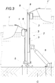
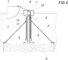
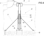
- the device for fixing floating bodies 1, 1 ' comprises a pile 2 which can be fixed at one end to the base G in the region of the other end of which the floating body 1, 1' can be fixed.
- the pile is designed as a telescopic tube, which in particular a Tidenhub T can be compensated advantageous.
- the pile is at its end facing away from the bottom G with a floating body 1, in particular a floating dock, equipped.
- the pile is at the bottom by means of a flange 4 at the bottom, a rock or a concrete tub, bolted. The relevant screwing is only hinted.
- the pile 2 is sharpened on the ground side and driven into the ground G.
- the post 2 in the exemplary embodiment Fig. 2 at one end and in the exemplary embodiment Fig. 1 Both ends equipped with a ball coupling 5.
- the pile 2 can also be tensioned by means of one end of the pile 2 and the other end on the base G attacking pendulum supports 6, or traction means 7.
- Fig. 2 While no such means are shown, they could of course be provided in this construction.
- the float 3 is a buoy, with which the device can be provided for example for generating a buoy field.
- the pile is equipped with a lifting force support.
- the Hubkraftunterstützung acts in the extension direction. This serves to create a counterweight to a floating example, on the pile floating dock.
- the illustrated Hubkraftunterstützung comprises a displaceable in the interior of the pile 2 counterweight 11 which engages over a deflection roller 12 deflected traction means 13 to a sub-tube 14 of the telescopic tube of the pile 2.
Landscapes
- Engineering & Computer Science (AREA)
- Ocean & Marine Engineering (AREA)
- General Engineering & Computer Science (AREA)
- Mechanical Engineering (AREA)
- Chemical & Material Sciences (AREA)
- Combustion & Propulsion (AREA)
- Environmental & Geological Engineering (AREA)
- Civil Engineering (AREA)
- Structural Engineering (AREA)
- Bridges Or Land Bridges (AREA)
- Piles And Underground Anchors (AREA)
- Revetment (AREA)
Description
- Die Erfindung bezieht sich auf eine Vorrichtung zum Festlegen von Schwimmkörpern mit einem einerends an einem Grund festlegbaren Pfahl, im Bereich dessen anderen Endes der Schwimmkörper vorgesehen ist, wobei der Pfahl als Teleskoprohr ausgebildet ist und wobei der Pfahl derart ausgebildet ist, dass sich die Pfahllänge selbständig den Tidenhubverhältnissen anpasst.
- Vorrichtungen der eingangs geschilderten Art sind beispielsweise aus der
JP H07 101382 A US 3 708 985 A bekannt. - Derartige Vorrichtungen dienen zum Festlegen von Schwimmkörpern jeglicher Art, insbesondere von Schwimmstegen, Booten, Schiffen u. dgl. Schwimmstege sind auf dem Wasser schwimmende Konstruktionen, an denen beispielsweise wiederum beliebige Schwimmkörper, wie Schiffe, Boote, Sportgeräte u. dgl. festgemacht werden können. Schwimmstege dienen in Gewässern mit Tidenhub als wasserstandsunabhängige Anlegestellen und in Häfen unter anderem auch zur Schaffung möglichst vieler Liegeplätze auf engem Raum. Die Auftriebskörper, üblicherweise sind mehrere vorgesehen, um bei einem Verlust eines oder einiger weniger Auftriebskörper nicht gleich den Verlust des gesamten Schwimmsteges in Kauf nehmen zu müssen, können aus beliebigem geeignetem Material gefertigt sein, wie beispielsweise aus Stahl, Aluminium, Beton oder Kunststoff.
- Um ein Abtreiben der Schwimmstege zu vermeiden werden diese mittels der am Grund festgelegten Pfähle, auch Piloten genannt, an der gewünschten Position gehalten. Schwimmstege dienen in Tiden-Gewässern als wasserstandsunabhängige Anlegestelle. In Sportboothäfen dienen sie zur Unterteilung der Wasserfläche und zur Nutzung für möglichst viele Liegeplätze. Die Pfähle werden zu diesem Zweck üblicher Weise mit Rammen entsprechend tief in den Grund getrieben und müssen bei Niederwasser entsprechend hoch über den Schwimmkörper aufragen, um diesen auch bei Hochwasser noch sicher halten und festlegen zu können. Nachteilig wirkt sich insbesondere aus, dass die Pfähle Tidenabhängig sehr hoch aus dem Wasser ragen können, dass die Pfähle Schwingungen des Schwimmkörpers praktisch nicht dämpfen können und dass die Pfähle konstruktionsbedingt stets mit entsprechendem Spiel in der Hubführung geführt sein müssen, was wiederum bei hoher auf die Konstruktion einwirkender kinetischer Energie, infolge von Seegang, wind u. dgl., eine Lockerung des Pfahles zur Folge haben kann.
- Das Festlegen von Schwimmkörpern aller Art, insbesondere von weiterführenden Stegen, Schiffen, Booten, Sportgeräten od. dgl. erfolgt üblicherweise durch ein Vertäuen des jeweiligen Schwimmkörpers am Schwimmsteg, wobei ein Schwimmkörper üblicherweise entweder längsseits oder quer zum Schwimmsteg anlegt. Nachteilig ist bei diesem Stand der Technik allerdings, dass der Schwimmsteg insbesondere bei widrigen Verhältnissen unruhig am Wasser liegt und nicht unerhebliche Eigenbewegungen beim Folgen der Wellenbewegungen ausführt, insbesondere diverse Biegungen und Verwindungen, was eine übermäßige Belastung für alle beteiligten Komponenten, wie Schwimmsteg, den anlegenden Schwimmkörpern und den Festmachermitteln, bedeutet.
- Weiters ist es bekannt, Schwimmkörper mittels Haltebäumen an Stegen, Hafenmauern od. dgl. zu befestigen (
WO 2009 015403 A1 ,WO 2014/110610 A1 ,NL 8 600 973 A WO 2009 015403 A1 insbesondere wenigstens einerends um eine zumindest annähernd vertikale Achse mit einem Beschlag drehfest bzw. drehfedernd am jeweiligen Festmacher festgelegt sind. Der Abstand vom Schwimmkörper zum Landungskörper wird mit den beiden Haltebäumen festgelegt, wobei eine Abtrift des Schwimmkörpers zur Seite und schräg nach hinten in Richtung Landungskörper durch ein drehfestes bzw. drehfederndes Festlegen der Beschläge an einem Ende der Haltebäume und/oder durch ein Abspannen der Haltebäume mit Springleinen unterbunden wird. Damit werden auf den Schwimmkörper einwirkende Wellen- und Windkräfte direkt über die Haltebäume in den Landungskörper eingeleitet. Damit können auf den Schwimmkörper einwirkende Kräfte, insbesondere bei höheren Windstärken und Wellengängen, bereits im Ansatz abgefedert und aufgefangen werden, womit eine wesentlich geringere Belastung von Schwimmkörper und Landungskörper gegeben ist. - Der Erfindung liegt ausgehend von einem Stand der Technik der vorgeschilderten Art die Aufgabe zugrunde, eine Vorrichtung zum Festlegen von Schwimmkörpern zu schaffen, welche die vorgenannten Nachteile vermeidet und die bei möglichst einfachem Aufbau ausreichend robust ist und auch bei widrigen Verhältnissen, insbesondere bei Wind und Wellengang, ein sicheres Festlegen von Schwimmkörpern erlaubt und dabei nicht, bzw. nicht im Übermaß, über die Wasseroberfläche vorragt.
- Die Erfindung löst diese Aufgabe dadurch, dass der Pfahl mittels einerends am Pfahl und anderends am Grund angreifender Pendelstützen abgespannt ist, wobei die Pendelstützen einerends am Pfahl und anderends am Grund mittels Beschlägen festgelegt sind und aus zwei ineinander teleskopartig verschiebbaren Stützenteilen bestehen, die gegeneinander durch eine Federeinrichtung sowohl in Zug- als auch in Druckrichtung abgestützt sind.
- Dadurch dass der Pfahl als Teleskoprohr ausgebildet ist und einerends am Grund festlegbar sowie anderends an seinem grundabgewandten Ende mit einem Schwimmkörper ausgestattet ist, passt sich die Pfahllänge selbständig problemlos den jeweiligen Tidenhubverhältnissen,aso den Wasserstandsverhältnissen an. Der Pfahl folgt somit hinsichtlich seiner Länge dem Wasserpegel. Der Schwimmkörper schwimmt dabei auf der Wasseroberfläche auf, ohne dass der Pfahl im Übermaß über eine Wasseroberfläche vorragt und bewirkt dabei die Verlagerung des Pfahls in die erforderliche Teleskoplage. Die Pfähle müssen nicht übermäßig, insbesondere gegebenenfalls gar nicht, über der Wasseroberfläche vorragen. Zudem ist bei entsprechender Ausgestaltung der Teleskopführung praktisch kein Spiel zwischen Schwimmkörper, Pfahl und Untergrund erforderlich bzw. vorhanden, was ein Losschlagen des Pfahles durch widrige Wellen bzw. Windverhältnisse vermeiden hilft. Schwimmkörper wie Schwimmstege, Anlegebojen für Boote bzw. beliebige Schwimmkörper können somit praktisch unsichtbar in idealer Lage gehalten werden, ohne große seitliche Abdriftungen in Kauf nehmen zu müssen. Durch die praktisch spielfreie Führung wird die Haltbarkeit wesentlich erhöht und werden die Wartungskosten erheblich gesenkt.
- Um den Pfahl besonders sicher verankern zu können bzw. um den Pfahl auch bei besonders widrigen Bodenverhältnissen sicher festlegen zu können, ist es vorgesehen den Pfahl mittels einerends am Pfahl und anderends am Grund angreifender Pendelstützen abzuspannen. Die Pendelstützen sind je einerends am Pfahl und anderends am Grund mittels Beschlägen festgelegt, wobei die Pendelstützen aus zwei ineinander teleskopartig verschiebbaren Stützenteilen bestehen, die gegeneinander durch eine Federeinrichtung sowohl in Zug- als auch in Druckrichtung abgestützt sind, also Zug- und Druckkräfte gefedert und ggf. gedämpft abtragen können. Die Federeinrichtung kann beispielsweise mit Abstand in Stützenlängsrichtung verteilt angeordneten Anschlagkörpern und mit zwischen den Anschlagkörpern vorgesehenen elastomeren Federkörpern ausgestattet sein, wobei die Anschlagkörper die Federkörper mit in Stützenlängsrichtung vorstehenden Anschlagansätzen unter Freilassung eines Aufnahmeraumes übergreifen, dessen Volumen zumindest dem Verdrängungsvolumen der elastomeren Federkörper in der Anschlagstellung der Anschlagkörper entspricht. Projiziert auf den Pfahlquerschnitt gesehen können ein, zwei, drei, vier oder mehrere Pendelstützen, insbesondere gleichverteilt um die Pfahllängsachse angeordnet sein, um den Pfahl zu stabilisieren.
- Insbesondere kann es vorgesehen sein, dass der Pfahl an seinem den Grund abgewandten Ende mit einem Schwimmkörper ausgestattet ist, der direkt am Pfahl befestigt ist. Dieser Schwimmkörper kann insbesondere beliebiger Natur sein. Beispielsweise sei näher angeführt, Schwimmstege, Bojen zum Festlegen von Booten oder dgl.
- Um auf die Vorrichtung einwirkende Kräfte durch Wind- und Wellengang möglichst geringen Grenzen halten zu können, ist es gemäß einer Weiterbildung der Erfindung vorgesehen, dass der entlang der Pfahlachse teleskopierbare Pfahl mit einem die Teleskopbewegung dämpfenden Schwingungsdämpfer ausgestattet sein kann. Dieser Schwingungsdämpfer funktioniert in äquivalenter Weise wie ein Schwingungsdämpfer bei einem Kraftfahrzeug, wobei das dämpfende Material entweder eine mechanisch elastisch deformierbare Dämpfungsmasse, wie beispielsweise Polyurethan, ein in einem geschlossenen Kreis geführtes Dämpferöl oder -gas ist bzw. von über entsprechenden Drosselöffnungen in das Pfahlinnere eindringendem Seewasser gebildet sein kann.
- Nach einer besonders vorteilhaften Weiterbildung der Erfindung kann der Pfahl mit einer in seiner Ausfahrrichtung wirkenden Hubkraftunterstützung ausgestattet sein. Dies bedeutet insbesondere, dass der dem Pfahlende zugeordnete Schwimmkörper nicht die gesamte Kraft zum Ausziehen des Teleskoprohres aufbringen muss, sondern dies durch die Hubkraftunterstützung unterstützt werden kann. Diese Hubkraftunterstützung kann beispielsweise ein im Inneren des Pfahls verlagerbares Gegengewicht umfassen, das über ein über eine Umlenkrolle umgelenktes Zugmittel an einer Teilröhre des Teleskoprohres angreift. Zudem bzw. alternativ dazu kann die Hubkraftunterstützung eine im Pfahlinneren vorgesehene Feder, gegebenenfalls eine Gasdruckfeder, umfassen.
- Zum Festlegen des Pfahles im Untergrund empfiehlt es sich, den Pfahl, der vorzugsweise grundseitig angespitzt ist, in den Grund zu treiben. Dazu wird der Pfahl mittels entsprechender Rammen, Schlageinrichtungen oder dgl. in den Grund getrieben. Zusätzlich bzw. alternativ könnte der Pfahl grundseitig mittels wenigstens eines Flansches am Grund festlegbar sein. Insbesondere bei harten, wie felsigen Gründen bzw. beim Festlegen auf Betonwannen oder dgl. werden die Pfähle vorzugsweise mittels der Flansche und entsprechender Dübel mit dem Untergrund verschraubt.
- Um das Teleskoprohr bei Wind- und Wellengang nicht übermäßig mit Querkräften zu belasten ist von Vorteil, wenn der Pfahl wenigstens einerends, gegebenenfalls beiderends, mit einer Kugelkupplung und/oder einem Kreuzgelenk ausgestattet ist. Bei Kugelköpfen können Neigungen von bis zu rund 35°aus einer Mittellage realisiert werden. Kreuzgelenke erlauben bis zu 90°.
- In der Zeichnung ist der Erfindungsgegenstand beispielsweise dargestellt. Es zeigen
-
Fig. 1 eine Vorrichtung im Querschnitt mit der Darstellung zweier Hublagen, -
Fig. 2 eine Konstruktionsvariante der Vorrichtung ausFig. 1 , -
Fig. 3 eine erfindungsgemäße weitere Konstruktionsvariante der Vorrichtung ausFig. 1 undFig. 2 , -
Fig. 4 eine Vorrichtung mit Hubkraftunterstützung im Querschnitt mit eingefahrenem Teleskoprohr und -
Fig. 5 die Vorrichtung ausFig. 4 mit ausgefahrenem Teleskoprohr. - Die Vorrichtung zum Festlegen von Schwimmkörpern 1, 1' umfasst einen einerends am Grund G festlegbaren Pfahl 2 im Bereich dessen anderen Endes der Schwimmkörper 1, 1' festlegbar ist. Gemäß der Erfindung ist der Pfahl als Teleskoprohr ausgebildet, womit insbesondere ein Tidenhub T vorteilhaft ausgeglichen werden kann. Im Ausführungsbeispiel nach den
Fig. 1 und2 ist der Pfahl an seinem den Grund G abgewandten Ende mit einem Schwimmkörper 1, insbesondere einem Schwimmsteg, ausgestattet. Im Ausführungsbeispiel nachFig. 1 ist der Pfahl dabei grundseitig mittels eines Flansches 4 am Grund, einem Felsen bzw. einer Betonwanne, verschraubt. Die diesbezügliche Verschraubung ist nur angedeutet. Im Ausführungsbeispiel nachFig. 2 ist der Pfahl 2 grundseitig angespitzt und in den Grund G getrieben. Zudem ist der Pfahl 2 im Ausführungsbeispiel nachFig. 2 einerends und im Ausführungsbeispiel nachFig. 1 beiderends mit einer Kugelkupplung 5 ausgestattet. - Der Pfahl 2 kann zudem mittels einerends am Pfahl 2 und anderends am Grund G angreifender Pendelstützen 6, bzw. Zugmittel 7 abgespannt sein. Im Ausführungsbeispiel nach
Fig. 2 sind zwar keine derartigen Mittel eingezeichnet, diese könnten allerdings naturgemäß bei dieser Konstruktion vorgesehen sein. - Im erfindungsgemäßen Ausführungsbeispiel nach
Fig. 3 ist der Schwimmkörper 3 eine Boje, womit die Vorrichtung beispielsweise zur Erzeugung eines Bojenfeldes vorgesehen werden kann. Ein Schiff 1' kann dann in üblicherweise mit der Boje bzw. mit dem Pfahl 2 an einem Anschlagmittel 8 festgelegt werden. Im Ausführungsbeispiel nachFig. 4 und5 ist der Pfahl mit einer Hubkraftunterstützung ausgestattet. Die Hubkraftunterstützung wirkt dabei in Ausfahrrichtung. Dies dient dazu, einen Gewichtsausgleich zu einem beispielsweise auf dem Pfahl aufruhenden Schwimmsteg zu schaffen. Die dargestellte Hubkraftunterstützung umfasst einen im Inneren des Pfahls 2 verlagerbares Gegengewicht 11, das über eine über eine Umlenkrolle 12 umgelenktes Zugmittel 13 an einer Teilröhre 14 des Teleskoprohres des Pfahls 2 angreift.
Claims (9)
- Vorrichtung zum Festlegen von Schwimmkörpern (1, 1') mit einem einerends an einem Grund (G) festlegbaren Pfahl (2), im Bereich dessen anderen Endes der Schwimmkörper (1, 1') festlegbar ist, wobei der Pfahl (2) als Teleskoprohr (3) ausgebildet ist und wobei der Pfahl (2) derart ausgebildet ist, dass sich die Pfahllänge selbständig den Tidenhubverhältnissen anpasst, dadurch gekennzeichnet, dass der Pfahl (2) mittels einerends am Pfahl (2) und anderends am Grund (G) angreifender Pendelstützen (6) abgespannt ist, wobei die Pendelstützen (6) einerends am Pfahl (2) und anderends am Grund (G) mittels Beschlägen festgelegt sind und aus zwei ineinander teleskopartig verschiebbaren Stützenteilen bestehen, die gegeneinander durch eine Federeinrichtung sowohl in Zug- als auch in Druckrichtung abgestützt sind.
- Vorrichtung nach Anspruch 1, dadurch gekennzeichnet, dass der Pfahl (2) an seinem Grund (G) abgewandten Ende mit einem Schwimmkörper (1, 1') ausgestattet ist.
- Vorrichtung nach Anspruch 1 oder 2, dadurch gekennzeichnet, dass der entlang der Pfahlachse (9) teleskopierbare Pfahl (2) mit einem die Teleskopbewegung dämpfenden Schwingungsdämpfer ausgestattet ist.
- Vorrichtung nach einem der Ansprüche 1 bis 3, dadurch gekennzeichnet, dass der Pfahl (2) mit einer in seiner Ausfahrrichtung wirkenden Hubkraftunterstützung ausgestattet ist.
- Vorrichtung nach Anspruch 4, dadurch gekennzeichnet, dass die Hubkraftunterstützung ein im inneren des Pfahls (2) verlagerbares Gegengewicht (11) umfasst, das über ein über eine Umlenkrolle (12) umgelenktes Zugmittel (13) an einer Teilröhre (14) des Teleskoprohres (3) angreift.
- Vorrichtung nach Anspruch 4, dadurch gekennzeichnet, dass die Hubkraftunterstützung eine im Pfahlinneren vorgesehene Feder, gegebenenfalls eine Gasdruckfeder umfasst.
- Vorrichtung nach einem der Ansprüche 1 bis 6, dadurch gekennzeichnet, dass der vorzugsweise grundseitig angespitzte Pfahl (2) in den Grund (G) getrieben ist.
- Vorrichtung nach einem der Ansprüche 1 bis 7, dadurch gekennzeichnet, dass der Pfahl (2) grundseitig mittels wenigstens eines Flansches (4) am Grund (G) festlegbar ist.
- Vorrichtung nach einem der Ansprüche 1 bis 8, dadurch gekennzeichnet, dass der Pfahl (2) wenigstens einerends mit einer Kugelkupplung (5) und/oder einem Kreuzgelenk ausgestattet ist.
Applications Claiming Priority (2)
| Application Number | Priority Date | Filing Date | Title |
|---|---|---|---|
| ATA50833/2014A AT516579A1 (de) | 2014-11-14 | 2014-11-14 | Vorrichtung zum Festlegen von Schwimmkörpern |
| PCT/AT2015/050289 WO2016074012A1 (de) | 2014-11-14 | 2015-11-12 | Vorrichtung zum festlegen von schwimmkörpern |
Publications (2)
| Publication Number | Publication Date |
|---|---|
| EP3218254A1 EP3218254A1 (de) | 2017-09-20 |
| EP3218254B1 true EP3218254B1 (de) | 2019-07-10 |
Family
ID=54848351
Family Applications (1)
| Application Number | Title | Priority Date | Filing Date |
|---|---|---|---|
| EP15808073.9A Active EP3218254B1 (de) | 2014-11-14 | 2015-11-12 | Vorrichtung zum festlegen von schwimmkörpern |
Country Status (5)
| Country | Link |
|---|---|
| US (1) | US10100478B2 (de) |
| EP (1) | EP3218254B1 (de) |
| CN (1) | CN107000815B (de) |
| AT (1) | AT516579A1 (de) |
| WO (1) | WO2016074012A1 (de) |
Families Citing this family (6)
| Publication number | Priority date | Publication date | Assignee | Title |
|---|---|---|---|---|
| US10364003B2 (en) * | 2016-05-17 | 2019-07-30 | Cmi Limited Co. | Hybrid fixed/floating marine structures |
| CN108507756A (zh) * | 2017-11-17 | 2018-09-07 | 浙江工业大学 | 波浪对方形桩柱作用荷载研究装置及其测试方法 |
| US11008720B2 (en) * | 2018-10-12 | 2021-05-18 | Adam Kirby | Floating dock piling height extension assembly and method |
| KR102273303B1 (ko) * | 2019-04-08 | 2021-07-06 | 김수환 | 부유식 수상지지장치 |
| EP3725665A1 (de) | 2019-04-16 | 2020-10-21 | Racing Yacht Management International Limited | Vorrichtung zum vertäuen von schwimmenden oberflächenanlagen, und entsprechendes verfahren |
| DE102022125006A1 (de) * | 2022-09-28 | 2024-03-28 | Robert Zimmermann | Solarschwimmvorrichtung |
Citations (1)
| Publication number | Priority date | Publication date | Assignee | Title |
|---|---|---|---|---|
| US4597350A (en) * | 1985-01-16 | 1986-07-01 | Texaco Inc. | Mooring system and liquid cargo transfer facility for ice infested waters |
Family Cites Families (22)
| Publication number | Priority date | Publication date | Assignee | Title |
|---|---|---|---|---|
| DE1938018A1 (de) * | 1969-07-23 | 1971-01-28 | Mannesmann Ag | Anlage zum Be- und Entladen von Tankschiffen |
| US3708985A (en) * | 1970-12-07 | 1973-01-09 | Texaco Inc | Articulated marine platform |
| FR2396126A1 (fr) | 1977-06-30 | 1979-01-26 | Emh | Systeme de colonne articulee pour l'exploitation des fonds marins notamment en mers glaciales |
| US4417646A (en) * | 1977-08-19 | 1983-11-29 | Charles Lindbergh | Counterweight system |
| GB2069954A (en) | 1980-02-22 | 1981-09-03 | Navire Cargo Gear Int Ab | A mooring device |
| SU891499A1 (ru) * | 1980-03-26 | 1981-12-23 | Проектно-Конструкторское Бюро Главного Управления Речного Флота При Совете Министров Усср | Передаточный плавучий док |
| IT1138085B (it) * | 1981-07-16 | 1986-09-10 | Tecnomare Spa | Struttura per l'ormeggio in alto mare |
| US4493282A (en) * | 1983-03-18 | 1985-01-15 | Exxon Production Research Co. | Combination mooring system |
| US4493283A (en) * | 1983-05-25 | 1985-01-15 | Elliott Richard E | Floating boat dock anchor |
| GB8334384D0 (en) * | 1983-12-23 | 1984-02-01 | Brewerton R W | Motion compensator |
| US4726313A (en) * | 1985-04-19 | 1988-02-23 | Harry Neal | Mooring boats |
| NL8600973A (nl) | 1986-04-17 | 1987-11-16 | Swarttouw Frans Bv | Afmeersysteem voor het afmeren van een ponton, schip of ander drijfbaar lichaam. |
| US5307753A (en) * | 1991-04-16 | 1994-05-03 | Besonen Sr Paul W | Water motion cushioning device |
| JPH07101382A (ja) | 1993-10-04 | 1995-04-18 | Zeniraito V:Kk | 灯浮標の係留装置 |
| US5347949A (en) * | 1993-11-08 | 1994-09-20 | Winston Paul K | Landlocked floating house |
| US7717053B2 (en) * | 2007-06-22 | 2010-05-18 | William Jayne | Spring line assembly |
| AT505530B1 (de) | 2007-08-01 | 2010-11-15 | Fuhrmann Michael Ing | Vorrichtung zum festlegen von schwimmkörpern |
| US20110107952A1 (en) * | 2009-11-11 | 2011-05-12 | Nicholson Iv John Wesley | Anchor system |
| ES2387366B1 (es) * | 2009-12-11 | 2013-04-26 | Grupo De Ingenieria Oceanica S.L. | Plataforma de medidas para su instalacion en el agua |
| CN203007945U (zh) * | 2012-12-03 | 2013-06-19 | 北京天工创道建筑科技有限公司 | 一种可以吸收地震波的抗震地锚装置 |
| AT515061B1 (de) | 2013-01-17 | 2015-10-15 | Dual Docker Gmbh | Vorrichtung zum Festlegen von Schwimmkörpern |
| CN203473192U (zh) * | 2013-08-05 | 2014-03-12 | 吴持跃 | 伸缩式桩柱 |
-
2014
- 2014-11-14 AT ATA50833/2014A patent/AT516579A1/de unknown
-
2015
- 2015-11-11 US US15/525,734 patent/US10100478B2/en active Active
- 2015-11-12 WO PCT/AT2015/050289 patent/WO2016074012A1/de active Application Filing
- 2015-11-12 EP EP15808073.9A patent/EP3218254B1/de active Active
- 2015-11-12 CN CN201580067875.6A patent/CN107000815B/zh active Active
Patent Citations (1)
| Publication number | Priority date | Publication date | Assignee | Title |
|---|---|---|---|---|
| US4597350A (en) * | 1985-01-16 | 1986-07-01 | Texaco Inc. | Mooring system and liquid cargo transfer facility for ice infested waters |
Also Published As
| Publication number | Publication date |
|---|---|
| US10100478B2 (en) | 2018-10-16 |
| CN107000815B (zh) | 2019-09-03 |
| US20170350083A1 (en) | 2017-12-07 |
| EP3218254A1 (de) | 2017-09-20 |
| CN107000815A (zh) | 2017-08-01 |
| WO2016074012A1 (de) | 2016-05-19 |
| AT516579A1 (de) | 2016-06-15 |
Similar Documents
| Publication | Publication Date | Title |
|---|---|---|
| EP3218254B1 (de) | Vorrichtung zum festlegen von schwimmkörpern | |
| EP3207186B1 (de) | Gründung eines offshore-bauwerks | |
| DE102010026117B4 (de) | Offshore-Anlage, insbesondere Windkraftanlage | |
| DE10034847A1 (de) | Ortsfeste Positionierung von Funktionseinheiten auf dem oder im Wasser | |
| DE102010020995B4 (de) | Gründungssystem für die Gründung einer Offshore-Windenergieanlage | |
| EP2512910A2 (de) | Unterwassertragsystemankerung für anlagen | |
| WO2003001009A1 (de) | Meerestechnische tragkonstruktion, insbesondere für eine offshore-windkraftanlage, und verfahren zur herstellung einer derartigen tragkonstruktionen | |
| EP2946039B1 (de) | Vorrichtung zum festlegen von schwimmkörpern | |
| EP2945850B1 (de) | Vorrichtung zum festlegen von schwimmkörpern | |
| DE202010010094U1 (de) | Gründungssystem für die Gründung einer Offshore-Windenergieanlage | |
| AT516670B1 (de) | Pontonbrücke | |
| DE2538642C3 (de) | Tauchfähige Rammvorrichtung | |
| DE2537918C3 (de) | Vorrichtung zur Abweisung von Eis von im Wasser vertikal stehenden Säulen, Pfeilern o.dgl. von in eisgefährdeten Seegebieten fest angeordneten oder schwimmenden Bauwerken | |
| DE102008017785A1 (de) | Fundament für ein Offshorebauwerk und Verfahren zum Erstellen eines Fundaments eines Offshorebauwerks | |
| EP3409838B1 (de) | Schwimmkörper zur ausbildung von brückenabschnitten | |
| DE202015001804U1 (de) | Modularer Ladekai | |
| DE202016007626U1 (de) | Schwimmende Seilgärten | |
| DE803103C (de) | Federnder Stahl-Streichpfahl | |
| DE102015104395A1 (de) | Schraubfundament | |
| DE202010017856U1 (de) | Offshore-Anlage, insbesondere Windkraftanlage | |
| DE102011102577B4 (de) | Schwimmvorrichtung und Verfahren zum Eindrücken eines Gegenstandes in einen Gewässerboden | |
| EP2898149A1 (de) | Schwimmkörperhubstelzensegment zum heben von schiffen oder plattformen sowie schwimmkörper | |
| AT513591A2 (de) | Kraftwerksanlage | |
| EP2650445A2 (de) | Auf den Meeresgrund absenkbares Grundelement für ortsfeste Einrichtungen |
Legal Events
| Date | Code | Title | Description |
|---|---|---|---|
| STAA | Information on the status of an ep patent application or granted ep patent |
Free format text: STATUS: THE INTERNATIONAL PUBLICATION HAS BEEN MADE |
|
| PUAI | Public reference made under article 153(3) epc to a published international application that has entered the european phase |
Free format text: ORIGINAL CODE: 0009012 |
|
| STAA | Information on the status of an ep patent application or granted ep patent |
Free format text: STATUS: REQUEST FOR EXAMINATION WAS MADE |
|
| 17P | Request for examination filed |
Effective date: 20170505 |
|
| AK | Designated contracting states |
Kind code of ref document: A1 Designated state(s): AL AT BE BG CH CY CZ DE DK EE ES FI FR GB GR HR HU IE IS IT LI LT LU LV MC MK MT NL NO PL PT RO RS SE SI SK SM TR |
|
| AX | Request for extension of the european patent |
Extension state: BA ME |
|
| DAV | Request for validation of the european patent (deleted) | ||
| DAX | Request for extension of the european patent (deleted) | ||
| STAA | Information on the status of an ep patent application or granted ep patent |
Free format text: STATUS: EXAMINATION IS IN PROGRESS |
|
| 17Q | First examination report despatched |
Effective date: 20180409 |
|
| REG | Reference to a national code |
Ref country code: DE Ref legal event code: R079 Ref document number: 502015009630 Country of ref document: DE Free format text: PREVIOUS MAIN CLASS: B63B0021000000 Ipc: B63B0021500000 |
|
| RIC1 | Information provided on ipc code assigned before grant |
Ipc: B63B 21/50 20060101AFI20181211BHEP |
|
| GRAP | Despatch of communication of intention to grant a patent |
Free format text: ORIGINAL CODE: EPIDOSNIGR1 |
|
| STAA | Information on the status of an ep patent application or granted ep patent |
Free format text: STATUS: GRANT OF PATENT IS INTENDED |
|
| INTG | Intention to grant announced |
Effective date: 20190213 |
|
| GRAS | Grant fee paid |
Free format text: ORIGINAL CODE: EPIDOSNIGR3 |
|
| GRAA | (expected) grant |
Free format text: ORIGINAL CODE: 0009210 |
|
| STAA | Information on the status of an ep patent application or granted ep patent |
Free format text: STATUS: THE PATENT HAS BEEN GRANTED |
|
| AK | Designated contracting states |
Kind code of ref document: B1 Designated state(s): AL AT BE BG CH CY CZ DE DK EE ES FI FR GB GR HR HU IE IS IT LI LT LU LV MC MK MT NL NO PL PT RO RS SE SI SK SM TR |
|
| REG | Reference to a national code |
Ref country code: GB Ref legal event code: FG4D Free format text: NOT ENGLISH |
|
| REG | Reference to a national code |
Ref country code: CH Ref legal event code: EP Ref country code: AT Ref legal event code: REF Ref document number: 1153292 Country of ref document: AT Kind code of ref document: T Effective date: 20190715 |
|
| REG | Reference to a national code |
Ref country code: DE Ref legal event code: R096 Ref document number: 502015009630 Country of ref document: DE |
|
| REG | Reference to a national code |
Ref country code: IE Ref legal event code: FG4D Free format text: LANGUAGE OF EP DOCUMENT: GERMAN |
|
| REG | Reference to a national code |
Ref country code: NL Ref legal event code: MP Effective date: 20190710 |
|
| REG | Reference to a national code |
Ref country code: LT Ref legal event code: MG4D |
|
| PG25 | Lapsed in a contracting state [announced via postgrant information from national office to epo] |
Ref country code: PT Free format text: LAPSE BECAUSE OF FAILURE TO SUBMIT A TRANSLATION OF THE DESCRIPTION OR TO PAY THE FEE WITHIN THE PRESCRIBED TIME-LIMIT Effective date: 20191111 Ref country code: FI Free format text: LAPSE BECAUSE OF FAILURE TO SUBMIT A TRANSLATION OF THE DESCRIPTION OR TO PAY THE FEE WITHIN THE PRESCRIBED TIME-LIMIT Effective date: 20190710 Ref country code: LT Free format text: LAPSE BECAUSE OF FAILURE TO SUBMIT A TRANSLATION OF THE DESCRIPTION OR TO PAY THE FEE WITHIN THE PRESCRIBED TIME-LIMIT Effective date: 20190710 Ref country code: SE Free format text: LAPSE BECAUSE OF FAILURE TO SUBMIT A TRANSLATION OF THE DESCRIPTION OR TO PAY THE FEE WITHIN THE PRESCRIBED TIME-LIMIT Effective date: 20190710 Ref country code: HR Free format text: LAPSE BECAUSE OF FAILURE TO SUBMIT A TRANSLATION OF THE DESCRIPTION OR TO PAY THE FEE WITHIN THE PRESCRIBED TIME-LIMIT Effective date: 20190710 Ref country code: NL Free format text: LAPSE BECAUSE OF FAILURE TO SUBMIT A TRANSLATION OF THE DESCRIPTION OR TO PAY THE FEE WITHIN THE PRESCRIBED TIME-LIMIT Effective date: 20190710 Ref country code: BG Free format text: LAPSE BECAUSE OF FAILURE TO SUBMIT A TRANSLATION OF THE DESCRIPTION OR TO PAY THE FEE WITHIN THE PRESCRIBED TIME-LIMIT Effective date: 20191010 Ref country code: NO Free format text: LAPSE BECAUSE OF FAILURE TO SUBMIT A TRANSLATION OF THE DESCRIPTION OR TO PAY THE FEE WITHIN THE PRESCRIBED TIME-LIMIT Effective date: 20191010 |
|
| PG25 | Lapsed in a contracting state [announced via postgrant information from national office to epo] |
Ref country code: LV Free format text: LAPSE BECAUSE OF FAILURE TO SUBMIT A TRANSLATION OF THE DESCRIPTION OR TO PAY THE FEE WITHIN THE PRESCRIBED TIME-LIMIT Effective date: 20190710 Ref country code: ES Free format text: LAPSE BECAUSE OF FAILURE TO SUBMIT A TRANSLATION OF THE DESCRIPTION OR TO PAY THE FEE WITHIN THE PRESCRIBED TIME-LIMIT Effective date: 20190710 Ref country code: AL Free format text: LAPSE BECAUSE OF FAILURE TO SUBMIT A TRANSLATION OF THE DESCRIPTION OR TO PAY THE FEE WITHIN THE PRESCRIBED TIME-LIMIT Effective date: 20190710 Ref country code: RS Free format text: LAPSE BECAUSE OF FAILURE TO SUBMIT A TRANSLATION OF THE DESCRIPTION OR TO PAY THE FEE WITHIN THE PRESCRIBED TIME-LIMIT Effective date: 20190710 Ref country code: IS Free format text: LAPSE BECAUSE OF FAILURE TO SUBMIT A TRANSLATION OF THE DESCRIPTION OR TO PAY THE FEE WITHIN THE PRESCRIBED TIME-LIMIT Effective date: 20191110 Ref country code: GR Free format text: LAPSE BECAUSE OF FAILURE TO SUBMIT A TRANSLATION OF THE DESCRIPTION OR TO PAY THE FEE WITHIN THE PRESCRIBED TIME-LIMIT Effective date: 20191011 |
|
| PG25 | Lapsed in a contracting state [announced via postgrant information from national office to epo] |
Ref country code: TR Free format text: LAPSE BECAUSE OF FAILURE TO SUBMIT A TRANSLATION OF THE DESCRIPTION OR TO PAY THE FEE WITHIN THE PRESCRIBED TIME-LIMIT Effective date: 20190710 |
|
| PG25 | Lapsed in a contracting state [announced via postgrant information from national office to epo] |
Ref country code: DK Free format text: LAPSE BECAUSE OF FAILURE TO SUBMIT A TRANSLATION OF THE DESCRIPTION OR TO PAY THE FEE WITHIN THE PRESCRIBED TIME-LIMIT Effective date: 20190710 Ref country code: PL Free format text: LAPSE BECAUSE OF FAILURE TO SUBMIT A TRANSLATION OF THE DESCRIPTION OR TO PAY THE FEE WITHIN THE PRESCRIBED TIME-LIMIT Effective date: 20190710 Ref country code: EE Free format text: LAPSE BECAUSE OF FAILURE TO SUBMIT A TRANSLATION OF THE DESCRIPTION OR TO PAY THE FEE WITHIN THE PRESCRIBED TIME-LIMIT Effective date: 20190710 Ref country code: RO Free format text: LAPSE BECAUSE OF FAILURE TO SUBMIT A TRANSLATION OF THE DESCRIPTION OR TO PAY THE FEE WITHIN THE PRESCRIBED TIME-LIMIT Effective date: 20190710 Ref country code: IT Free format text: LAPSE BECAUSE OF FAILURE TO SUBMIT A TRANSLATION OF THE DESCRIPTION OR TO PAY THE FEE WITHIN THE PRESCRIBED TIME-LIMIT Effective date: 20190710 |
|
| PG25 | Lapsed in a contracting state [announced via postgrant information from national office to epo] |
Ref country code: SM Free format text: LAPSE BECAUSE OF FAILURE TO SUBMIT A TRANSLATION OF THE DESCRIPTION OR TO PAY THE FEE WITHIN THE PRESCRIBED TIME-LIMIT Effective date: 20190710 Ref country code: SK Free format text: LAPSE BECAUSE OF FAILURE TO SUBMIT A TRANSLATION OF THE DESCRIPTION OR TO PAY THE FEE WITHIN THE PRESCRIBED TIME-LIMIT Effective date: 20190710 Ref country code: IS Free format text: LAPSE BECAUSE OF FAILURE TO SUBMIT A TRANSLATION OF THE DESCRIPTION OR TO PAY THE FEE WITHIN THE PRESCRIBED TIME-LIMIT Effective date: 20200224 Ref country code: CZ Free format text: LAPSE BECAUSE OF FAILURE TO SUBMIT A TRANSLATION OF THE DESCRIPTION OR TO PAY THE FEE WITHIN THE PRESCRIBED TIME-LIMIT Effective date: 20190710 |
|
| REG | Reference to a national code |
Ref country code: DE Ref legal event code: R097 Ref document number: 502015009630 Country of ref document: DE |
|
| REG | Reference to a national code |
Ref country code: CH Ref legal event code: PL |
|
| PLBE | No opposition filed within time limit |
Free format text: ORIGINAL CODE: 0009261 |
|
| STAA | Information on the status of an ep patent application or granted ep patent |
Free format text: STATUS: NO OPPOSITION FILED WITHIN TIME LIMIT |
|
| PG2D | Information on lapse in contracting state deleted |
Ref country code: IS |
|
| PG25 | Lapsed in a contracting state [announced via postgrant information from national office to epo] |
Ref country code: CH Free format text: LAPSE BECAUSE OF NON-PAYMENT OF DUE FEES Effective date: 20191130 Ref country code: MC Free format text: LAPSE BECAUSE OF FAILURE TO SUBMIT A TRANSLATION OF THE DESCRIPTION OR TO PAY THE FEE WITHIN THE PRESCRIBED TIME-LIMIT Effective date: 20190710 Ref country code: LI Free format text: LAPSE BECAUSE OF NON-PAYMENT OF DUE FEES Effective date: 20191130 Ref country code: LU Free format text: LAPSE BECAUSE OF NON-PAYMENT OF DUE FEES Effective date: 20191112 |
|
| 26N | No opposition filed |
Effective date: 20200603 |
|
| REG | Reference to a national code |
Ref country code: BE Ref legal event code: MM Effective date: 20191130 |
|
| PG25 | Lapsed in a contracting state [announced via postgrant information from national office to epo] |
Ref country code: SI Free format text: LAPSE BECAUSE OF FAILURE TO SUBMIT A TRANSLATION OF THE DESCRIPTION OR TO PAY THE FEE WITHIN THE PRESCRIBED TIME-LIMIT Effective date: 20190710 |
|
| PG25 | Lapsed in a contracting state [announced via postgrant information from national office to epo] |
Ref country code: IE Free format text: LAPSE BECAUSE OF NON-PAYMENT OF DUE FEES Effective date: 20191112 |
|
| PG25 | Lapsed in a contracting state [announced via postgrant information from national office to epo] |
Ref country code: BE Free format text: LAPSE BECAUSE OF NON-PAYMENT OF DUE FEES Effective date: 20191130 |
|
| PG25 | Lapsed in a contracting state [announced via postgrant information from national office to epo] |
Ref country code: CY Free format text: LAPSE BECAUSE OF FAILURE TO SUBMIT A TRANSLATION OF THE DESCRIPTION OR TO PAY THE FEE WITHIN THE PRESCRIBED TIME-LIMIT Effective date: 20190710 |
|
| PG25 | Lapsed in a contracting state [announced via postgrant information from national office to epo] |
Ref country code: HU Free format text: LAPSE BECAUSE OF FAILURE TO SUBMIT A TRANSLATION OF THE DESCRIPTION OR TO PAY THE FEE WITHIN THE PRESCRIBED TIME-LIMIT; INVALID AB INITIO Effective date: 20151112 Ref country code: MT Free format text: LAPSE BECAUSE OF FAILURE TO SUBMIT A TRANSLATION OF THE DESCRIPTION OR TO PAY THE FEE WITHIN THE PRESCRIBED TIME-LIMIT Effective date: 20190710 |
|
| REG | Reference to a national code |
Ref country code: AT Ref legal event code: MM01 Ref document number: 1153292 Country of ref document: AT Kind code of ref document: T Effective date: 20201112 |
|
| PG25 | Lapsed in a contracting state [announced via postgrant information from national office to epo] |
Ref country code: AT Free format text: LAPSE BECAUSE OF NON-PAYMENT OF DUE FEES Effective date: 20201112 |
|
| PG25 | Lapsed in a contracting state [announced via postgrant information from national office to epo] |
Ref country code: MK Free format text: LAPSE BECAUSE OF FAILURE TO SUBMIT A TRANSLATION OF THE DESCRIPTION OR TO PAY THE FEE WITHIN THE PRESCRIBED TIME-LIMIT Effective date: 20190710 |
|
| PGFP | Annual fee paid to national office [announced via postgrant information from national office to epo] |
Ref country code: GB Payment date: 20221122 Year of fee payment: 8 Ref country code: FR Payment date: 20221122 Year of fee payment: 8 Ref country code: DE Payment date: 20221128 Year of fee payment: 8 |