EP3216973A1 - Dispositif d'ombrage de batiment et systeme de support associe - Google Patents
Dispositif d'ombrage de batiment et systeme de support associe Download PDFInfo
- Publication number
- EP3216973A1 EP3216973A1 EP16020077.0A EP16020077A EP3216973A1 EP 3216973 A1 EP3216973 A1 EP 3216973A1 EP 16020077 A EP16020077 A EP 16020077A EP 3216973 A1 EP3216973 A1 EP 3216973A1
- Authority
- EP
- European Patent Office
- Prior art keywords
- bearing plate
- bearing
- winding shaft
- plate
- shaft
- Prior art date
- Legal status (The legal status is an assumption and is not a legal conclusion. Google has not performed a legal analysis and makes no representation as to the accuracy of the status listed.)
- Granted
Links
- 238000004804 winding Methods 0.000 claims abstract description 70
- 238000006073 displacement reaction Methods 0.000 claims description 9
- 238000003780 insertion Methods 0.000 claims description 8
- 230000037431 insertion Effects 0.000 claims description 8
- 238000009434 installation Methods 0.000 description 7
- 238000010276 construction Methods 0.000 description 3
- 230000008921 facial expression Effects 0.000 description 2
- 238000012986 modification Methods 0.000 description 2
- 230000004048 modification Effects 0.000 description 2
- 238000013459 approach Methods 0.000 description 1
- 230000005484 gravity Effects 0.000 description 1
- 230000003313 weakening effect Effects 0.000 description 1
Images


Classifications
-
- E—FIXED CONSTRUCTIONS
- E06—DOORS, WINDOWS, SHUTTERS, OR ROLLER BLINDS IN GENERAL; LADDERS
- E06B—FIXED OR MOVABLE CLOSURES FOR OPENINGS IN BUILDINGS, VEHICLES, FENCES OR LIKE ENCLOSURES IN GENERAL, e.g. DOORS, WINDOWS, BLINDS, GATES
- E06B9/00—Screening or protective devices for wall or similar openings, with or without operating or securing mechanisms; Closures of similar construction
- E06B9/02—Shutters, movable grilles, or other safety closing devices, e.g. against burglary
- E06B9/08—Roll-type closures
- E06B9/11—Roller shutters
- E06B9/17—Parts or details of roller shutters, e.g. suspension devices, shutter boxes, wicket doors, ventilation openings
- E06B9/174—Bearings specially adapted therefor
-
- E—FIXED CONSTRUCTIONS
- E06—DOORS, WINDOWS, SHUTTERS, OR ROLLER BLINDS IN GENERAL; LADDERS
- E06B—FIXED OR MOVABLE CLOSURES FOR OPENINGS IN BUILDINGS, VEHICLES, FENCES OR LIKE ENCLOSURES IN GENERAL, e.g. DOORS, WINDOWS, BLINDS, GATES
- E06B9/00—Screening or protective devices for wall or similar openings, with or without operating or securing mechanisms; Closures of similar construction
- E06B9/24—Screens or other constructions affording protection against light, especially against sunshine; Similar screens for privacy or appearance; Slat blinds
- E06B9/40—Roller blinds
- E06B9/42—Parts or details of roller blinds, e.g. suspension devices, blind boxes
- E06B9/50—Bearings specially adapted therefor
-
- E—FIXED CONSTRUCTIONS
- E06—DOORS, WINDOWS, SHUTTERS, OR ROLLER BLINDS IN GENERAL; LADDERS
- E06B—FIXED OR MOVABLE CLOSURES FOR OPENINGS IN BUILDINGS, VEHICLES, FENCES OR LIKE ENCLOSURES IN GENERAL, e.g. DOORS, WINDOWS, BLINDS, GATES
- E06B9/00—Screening or protective devices for wall or similar openings, with or without operating or securing mechanisms; Closures of similar construction
- E06B9/02—Shutters, movable grilles, or other safety closing devices, e.g. against burglary
- E06B9/08—Roll-type closures
- E06B9/11—Roller shutters
- E06B9/17—Parts or details of roller shutters, e.g. suspension devices, shutter boxes, wicket doors, ventilation openings
- E06B9/174—Bearings specially adapted therefor
- E06B2009/1746—Axial connection of rollers
Definitions
- the invention relates to a building opening shading device with a motor-driven winding shaft, as well as a bearing arrangement for mounting one end of the motor-driven winding shaft on an associated side part of a winding shaft box according to the preamble of claim 1.
- the German Utility Model DE 29 804 060 U1 shows a bearing assembly for supporting a winding shaft end on a side part, wherein the side part has a receptacle for a mounted on the motor side winding shaft end bearing plate.
- Transverse to the winding shaft axis direction guides are provided on the upper and lower sides of the recording, in which the bearing plate can be inserted from the side.
- the bearing plate After inserting the bearing plate in the receptacle on the side part yet another end piece is pushed to fix the bearing plate in its retracted end position.
- the bearing plate is formed integrally with the drive motor of the winding shaft, so that the insertion of the bearing plate into the receptacle must be made when molded onto the motor and thus the entire winding shaft bearing plate. In most cases, however, the necessary mounting space for today's shutters or other building opening shading devices is not available.
- bearing plates which have shaft receptacles for the motor-side end of a winding shaft on which the winding shaft with corresponding adapters after insertion of the bearing plate on the assigned box side part can be attached.
- EP 1 160 414 A1 one with side tabs in the rear grip on corresponding recesses on the box side part bearing plate with a shaft receiving, in which the winding shaft with a mounted on the winding shaft motor adapter is subsequently inserted.
- the bearing assembly according to the invention has a side part and a bearing plate.
- the plate holder on two opposite sides transverse to the shaft axis extending, parallel side guides and the flat body of the bearing plate has two corresponding guided on the side guides sliding sides. The frontally inserted into the disc holder bearing plate can then be moved with its two displacement sides along the side guides from a starting position to an end position.
- the Langeran extract is inventively characterized in that it allows insertion and a rotational and stationary fixing of the bearing plate in the disc holder in exactly two positions, namely a standard position and a contrast 180 ° to the winding shaft in the installed state associated shaft axis rotated variant position ,
- the bearing assembly according to the invention is also characterized by the fact that the shaft mount is arranged at such an off-center position on the flat body of the bearing plate, that they set at offset in the variant position in the disc holder bearing plate offset to the position of the shaft recording in the default position in the disc holder Has bearing plate.
- the bearing plate can be used in only two positions in the disc holder, a simple mounting on the type of EP 1 160 414 A1 Ensured adapted to the bearing plate plate holder on the box side part, by the off-center positioning of the Shaft mount on the flat body of the bearing plate, however, provided a more universal application of the bearing assembly.
- the winding shaft In a winding shaft box, the winding shaft can thus be arranged in two positions, which may be required for differently long hangings and thus different thickness bales on the winding shafts.
- the same winding shaft with the same curtain in two different winding shaft boxes with different side parts, which, however, each have the same plate holder, are supported at the necessary, different positions.
- the building opening shading device has the bearing arrangement according to the invention on at least one winding shaft end.
- An even simpler installation and further modularization based on the modular principle results when the building opening shading device has a bearing plate on its motor-side winding shaft end, which has a suitable for rotationally fixed support of the motor side winding shaft end shaft receiving and at its other end a bearing plate, the one for rotatable mounting of the motor facing away Wickelwellenendes suitable shaft receiving, the two flat bodies of the two bearing plates are dimensioned the same and the shaft receptacles are arranged on the flat bodies so that in the installed state, the position of the shaft receiving on the flat body of a bearing plate corresponds to the position of the shaft receiving on the flat body of the other bearing plate ,
- the bearing plate may accordingly also have shaft receptacles adapted to other drive types (for example belt drive or crank drive), so that several variants of bearing plates can exist.
- the bearing plate Due to the offset of the shaft axis or the position of the shaft mount on the flat body in the standard position relative to that on the flat body in variant position, the bearing plates, which are provided for installation on a left side part of the winding shaft box, differ from those which are intended for installation on a right side part.
- the bearing plate advantageously has a coding, for example in the form of a molded or printed label or certain position marks, which indicates which side of the two sides of the winding shaft box, the bearing plate belongs. Since the positions of the shaft axis in standard position and variant position may also differ only slightly from each other, it is also useful to provide the bearing plate with a coding that indicates whether it is in standard position or (over head) in variant position. In the case of an encoding designed as a label, which belongs to the bearing plate on the box side, the coding standard position / variant position results by itself. Because in variant position the inscription stands on its head.
- the side guides on the plate holder and thus the displacement sides of the flat body of the bearing plate thereby extend in the horizontal direction, since in this direction the space is also greatest for provided for narrow installation space box side panels.
- the bearing arrangement advantageously has a transverse locking device with which the bearing plate can be locked in the end position against shifting back.
- the cross-locking device can be particularly easy to install and inexpensive to implement, if it has a clamping or locking piece, which is located in the end position bearing plate between a located on the side of the starting position edge portion of the disc holder and the edge in the standard position or the variant position respectively facing side portion can be clamped or locked.
- the bearing assembly as a security against withdrawal of the bearing plate from the disc holder in Wellenachs512 to the box inside towards a longitudinal locking device with which the bearing plate is locked in the end position against withdrawal in Wellenachs512.
- the bearing plate is supported in the disk holder.
- the longitudinal locking device is formed on the two side guides or displacement sides.
- the longitudinal locking device each having a crenellated series of retaining tabs on the two side guides of the disc holder, which is associated with a crenellated series of trailing tabs on the two displacement sides of the bearing plate, the rows of trailing tabs when inserting the bearing plate in the starting position in the disc holder the Pass through rows of retaining tabs and reach behind after moving to the final position.
- the flat body of the bearing plate thereby has an overall point-symmetrical shape. Because then a provided on one side stop edge on the disc holder regardless serve as a stop, whether the bearing plate is inserted in the standard position or in variant position in the disc holder. Similarly, regardless of whether the bearing plate is inserted in the standard position or in variant position in the disc holder, which serves as a transverse locking device clamping piece then fits between the opposite side edge of the flat body and an associated wall of the disc holder. This creates a nearly completely circumferential positive connection between the bearing plate, side part and locking member, which effectively prevents an independent release, for example, by vibrations during transport.
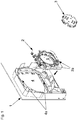
- the bearing plate 2 has a plate-shaped flat body with a shaft receptacle 5 designed to receive a motor-side winding shaft end.
- the shaft receptacle 5 has a cylindrical projecting from the flat body wall, are provided on the radially inwardly projecting retaining tabs.
- the bearing assembly has a round adapter disc 3, which is attachable to the front end of the tubular motor of the winding shaft and radially projecting rear grip tabs, which can be brought into the shaft holder 5 by turning in the rear grip on the holding tabs provided there.
- a locking device is provided to lock the motor end to its adapter disc 3 in the shaft receiving 5 against rotation.
- the flat body of the bearing plate 2 in this case has two horizontally extending, mutually opposite side edges or sliding sides 2a, which are associated with the plate receiving 4 corresponding side guides or guideways 4a.
- the side guides 4a have on the side facing away from the winding shaft box outside edge portions on which the bearing plate 2 can be axially supported, and at right angles to horizontally extending wall sections on which the bearing plate 2 is supported horizontally displaceable.
- FIG. 2 shows the inserted into the disc holder 4 bearing plate 2. It can be seen on the sliding sides 2a outwardly projecting rear grip plates 8, which pushed when inserting the bearing plate 2 in the disc holder 4 by corresponding recesses between the side guides 4a inwardly projecting retaining tabs 9 will or will be successful.
- the bearing plate 2 In the presentation of the Fig. 2 is the bearing plate 2 while in its inserted into the disc holder 4 starting position against a displacement along the side guides 4a in the in the Fig. 3 shown end position.
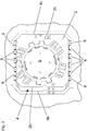
- the bearing plate 2 in this case has a plate-shaped flat body, which carries the shaft seat 5.
- the plate-shaped flat body is formed point-symmetrical and therefore has on the side opposite the side edge 2c an identically extending, namely in the installed position vertical side edge 2b.
- the side edge 2b is in turn associated with a corresponding side edge 4b on the disc holder 4, which, like Fig. 3 shows, serves as a stop for the shifted in the end position bearing plate 2.
- the bearing plate 2 is also symmetrical with respect to a horizontal axis of symmetry, so that they are in the in Fig. 3 shown standard position, but also in a rotated by 180 ° about the shaft axis, in Fig. 4 can be used in the disk holder 4 shown variant version. Since the shaft 5 is eccentrically located on the flat body of the bearing plate 2, thereby the placement of the winding shaft on the side part 1 of the in Fig. 3 shown position diagonally down in the in Fig. 4 Move shown position in which one uses the bearing plate 2 instead of in their default position in their variant position in the disc holder 4.
- a cuboid locking piece 6 serves as a transverse locking device against unwanted displacement of the bearing plate 2 located in the end position in the horizontal direction.
- the locking piece 6 has for this purpose a latching projection 6a, with which it is brought into engagement with the flat body of the bearing plate 2 during insertion into the space between the vertical side edge 4c of the plate holder 4 and the vertical side edge 2c of the bearing plate 2.
- How to get the Fig. 6 , but also the 3 and 4 takes, are the rear grip tabs 8 of the bearing plate 3 in located in the end position bearing plate 2 in the rear grip on the retaining tabs 9 of the disc holder. 4
- the bearing assembly is not only suitable for supporting a motor-side winding shaft end. Rather, the same facial expressions may also be provided for introducing the bearing plate 2 in the PlattenaufEnglishung 4 on a bearing plate 102, which carries a shaft journal a bearing pin 105 for the motor facing away, so rotatably mounted end of the winding shaft, as from a synopsis of FIGS. 7 and 8 becomes clear.
- FIGS. 9 and 10 show respective bearing plates 202 to the arrangement on the left side of the box or 2 to the arrangement on the right side of the box. Both bear a corresponding coding 7, consisting of the letters "L" and "R” and two arrow marks indicating which box side the respective bearing plate is intended. How to do that FIGS. 3 and 4 removes, the fitter on the basis of the coding 7 in each case can also recognize whether the bearing plate is in its default position or in their variant position in which the letter is then upside down.
Landscapes
- Engineering & Computer Science (AREA)
- Structural Engineering (AREA)
- Architecture (AREA)
- Civil Engineering (AREA)
- Operating, Guiding And Securing Of Roll- Type Closing Members (AREA)
Priority Applications (1)
| Application Number | Priority Date | Filing Date | Title |
|---|---|---|---|
| EP16020077.0A EP3216973B1 (fr) | 2016-03-10 | 2016-03-10 | Dispositif d'ombrage de batiment et systeme de support associe |
Applications Claiming Priority (1)
| Application Number | Priority Date | Filing Date | Title |
|---|---|---|---|
| EP16020077.0A EP3216973B1 (fr) | 2016-03-10 | 2016-03-10 | Dispositif d'ombrage de batiment et systeme de support associe |
Publications (2)
| Publication Number | Publication Date |
|---|---|
| EP3216973A1 true EP3216973A1 (fr) | 2017-09-13 |
| EP3216973B1 EP3216973B1 (fr) | 2019-05-29 |
Family
ID=55527223
Family Applications (1)
| Application Number | Title | Priority Date | Filing Date |
|---|---|---|---|
| EP16020077.0A Active EP3216973B1 (fr) | 2016-03-10 | 2016-03-10 | Dispositif d'ombrage de batiment et systeme de support associe |
Country Status (1)
| Country | Link |
|---|---|
| EP (1) | EP3216973B1 (fr) |
Citations (10)
| Publication number | Priority date | Publication date | Assignee | Title |
|---|---|---|---|---|
| DE29804060U1 (de) | 1998-03-07 | 1998-07-16 | Elket Kunststoff Technik Gmbh | Rolladenaggregat |
| FR2781837A1 (fr) | 1998-07-30 | 2000-02-04 | Franciaflex Ind | Dispositif de montage pour moteur de volet roulant |
| EP1160414A1 (fr) | 2000-05-31 | 2001-12-05 | Simbac S.p.A | Dispositif formant support d'extrémité pour un arbre d'enroulement, son procédé d'assemblage et mécanisme de manoeuvre d'une installation de fermeture ou de protection solaire comprenant un tel dispositif |
| EP1184534A2 (fr) | 2000-09-01 | 2002-03-06 | Ennio Montagna | Volet roulant |
| FR2826398A1 (fr) * | 2001-06-20 | 2002-12-27 | Ms Dev | Dispositif obturateur destine a fermer chacune des deux extremites laterales d'un coffre-tunnel pour volet roulant |
| DE202005005544U1 (de) | 2005-04-08 | 2005-07-14 | Gunkel Gmbh | Universalmotorlager für einen Rollladen, Markise o.dgl. |
| EP2031175A1 (fr) * | 2007-08-25 | 2009-03-04 | WAREMA Renkhoff GmbH | Elément latéral pour un boîtier de store |
| DE202009003226U1 (de) * | 2009-03-06 | 2009-05-20 | Alulux Beckhoff Gmbh & Co. Kg | Rollladenkasten |
| WO2013124494A1 (fr) | 2012-02-23 | 2013-08-29 | Gaviota Simbac, S.L. | Dispositif de support polyvalent |
| EP2677106A1 (fr) | 2012-06-23 | 2013-12-25 | Alukon GmbH & Co. KG | Plaque d'appui pour l'arbre d'enroulement d'un volet roulant |
-
2016
- 2016-03-10 EP EP16020077.0A patent/EP3216973B1/fr active Active
Patent Citations (10)
| Publication number | Priority date | Publication date | Assignee | Title |
|---|---|---|---|---|
| DE29804060U1 (de) | 1998-03-07 | 1998-07-16 | Elket Kunststoff Technik Gmbh | Rolladenaggregat |
| FR2781837A1 (fr) | 1998-07-30 | 2000-02-04 | Franciaflex Ind | Dispositif de montage pour moteur de volet roulant |
| EP1160414A1 (fr) | 2000-05-31 | 2001-12-05 | Simbac S.p.A | Dispositif formant support d'extrémité pour un arbre d'enroulement, son procédé d'assemblage et mécanisme de manoeuvre d'une installation de fermeture ou de protection solaire comprenant un tel dispositif |
| EP1184534A2 (fr) | 2000-09-01 | 2002-03-06 | Ennio Montagna | Volet roulant |
| FR2826398A1 (fr) * | 2001-06-20 | 2002-12-27 | Ms Dev | Dispositif obturateur destine a fermer chacune des deux extremites laterales d'un coffre-tunnel pour volet roulant |
| DE202005005544U1 (de) | 2005-04-08 | 2005-07-14 | Gunkel Gmbh | Universalmotorlager für einen Rollladen, Markise o.dgl. |
| EP2031175A1 (fr) * | 2007-08-25 | 2009-03-04 | WAREMA Renkhoff GmbH | Elément latéral pour un boîtier de store |
| DE202009003226U1 (de) * | 2009-03-06 | 2009-05-20 | Alulux Beckhoff Gmbh & Co. Kg | Rollladenkasten |
| WO2013124494A1 (fr) | 2012-02-23 | 2013-08-29 | Gaviota Simbac, S.L. | Dispositif de support polyvalent |
| EP2677106A1 (fr) | 2012-06-23 | 2013-12-25 | Alukon GmbH & Co. KG | Plaque d'appui pour l'arbre d'enroulement d'un volet roulant |
Also Published As
| Publication number | Publication date |
|---|---|
| EP3216973B1 (fr) | 2019-05-29 |
Similar Documents
| Publication | Publication Date | Title |
|---|---|---|
| EP0433726B1 (fr) | Système de porte repliable coulissante vers l'intérieur d'une armoire | |
| EP2616621B1 (fr) | Grille de protection | |
| EP2604778A1 (fr) | Paroi coulissante pliante, train de roulement et rail de guidage | |
| EP2385210B1 (fr) | Engrenage planétaire pour moteurs d'entraînement | |
| EP3486420B1 (fr) | Procédé de positionnement d'une fenêtre ou d'une porte | |
| EP0677131B1 (fr) | Dispositif de fermeture pour portes de boitiers ou de placards | |
| DE202012008665U1 (de) | Anordnung zum Befestigen eines Pfostens an einer Rahmenleiste eines Fensters oder einer Türe mittels eines Pfostenverbinders | |
| EP0293614B1 (fr) | Boîte d'installation électrique dans des parois creuses, notamment pour interrupteurs, prises de courant et choses similaires | |
| EP1698755B1 (fr) | Coffre de volet roulant | |
| DE202007004845U1 (de) | Teleskopansatz für Rolladenachse | |
| EP2500507B1 (fr) | Support du carter supérieur | |
| EP3216973B1 (fr) | Dispositif d'ombrage de batiment et systeme de support associe | |
| DE19711311A1 (de) | Halterung für einen Rolladen oder für ein Rolltor | |
| EP3216971A1 (fr) | Dispositif d'ombrage de bâtiment et système de support pour l'arbre d'enroulement associé | |
| DE102013000278B4 (de) | Gebäudeöffnungsverschattungsvorrichtung und Achskappenmodul für die Wickelwelle der Gebäudeöffnungsverschattungsvorrichtung | |
| DE102014009502A1 (de) | Gebäudeverschattungsvorrichtung und Seitenführungsschiene dafür | |
| DE102006001045B4 (de) | Eckverbinder für Tür- oder Fensterrahmen | |
| EP2677106B1 (fr) | Plaque d'appui pour l'arbre d'enroulement d'un volet roulant | |
| DE10000162C2 (de) | Rolladenkasten | |
| EP0416201A1 (fr) | Dispositif protecteur pour espaces de rentrage sur des transporteurs de bande | |
| DE202006014701U1 (de) | Nachrüstsatz für Verdunkelungs- und/oder Sicherungsvorrichtungen | |
| DE10304908B4 (de) | Rollladen | |
| EP2918770A1 (fr) | Dispositif d'ombrage d'ouverture de bâtiment et module de palier latéral pour un arbre d'enroulement du dispositif d'ombrage d'ouverture de bâtiment | |
| EP3670816A1 (fr) | Dispositif d'entraînement pour un pare-soleil d'ouverture de bâtiment | |
| WO1999025995A1 (fr) | Broche d'entrainement |
Legal Events
| Date | Code | Title | Description |
|---|---|---|---|
| PUAI | Public reference made under article 153(3) epc to a published international application that has entered the european phase |
Free format text: ORIGINAL CODE: 0009012 |
|
| STAA | Information on the status of an ep patent application or granted ep patent |
Free format text: STATUS: THE APPLICATION HAS BEEN PUBLISHED |
|
| AK | Designated contracting states |
Kind code of ref document: A1 Designated state(s): AL AT BE BG CH CY CZ DE DK EE ES FI FR GB GR HR HU IE IS IT LI LT LU LV MC MK MT NL NO PL PT RO RS SE SI SK SM TR |
|
| AX | Request for extension of the european patent |
Extension state: BA ME |
|
| STAA | Information on the status of an ep patent application or granted ep patent |
Free format text: STATUS: REQUEST FOR EXAMINATION WAS MADE |
|
| 17P | Request for examination filed |
Effective date: 20180207 |
|
| RBV | Designated contracting states (corrected) |
Designated state(s): AL AT BE BG CH CY CZ DE DK EE ES FI FR GB GR HR HU IE IS IT LI LT LU LV MC MK MT NL NO PL PT RO RS SE SI SK SM TR |
|
| GRAP | Despatch of communication of intention to grant a patent |
Free format text: ORIGINAL CODE: EPIDOSNIGR1 |
|
| STAA | Information on the status of an ep patent application or granted ep patent |
Free format text: STATUS: GRANT OF PATENT IS INTENDED |
|
| INTG | Intention to grant announced |
Effective date: 20190125 |
|
| GRAS | Grant fee paid |
Free format text: ORIGINAL CODE: EPIDOSNIGR3 |
|
| GRAA | (expected) grant |
Free format text: ORIGINAL CODE: 0009210 |
|
| STAA | Information on the status of an ep patent application or granted ep patent |
Free format text: STATUS: THE PATENT HAS BEEN GRANTED |
|
| AK | Designated contracting states |
Kind code of ref document: B1 Designated state(s): AL AT BE BG CH CY CZ DE DK EE ES FI FR GB GR HR HU IE IS IT LI LT LU LV MC MK MT NL NO PL PT RO RS SE SI SK SM TR |
|
| REG | Reference to a national code |
Ref country code: GB Ref legal event code: FG4D Free format text: NOT ENGLISH |
|
| REG | Reference to a national code |
Ref country code: CH Ref legal event code: EP |
|
| REG | Reference to a national code |
Ref country code: AT Ref legal event code: REF Ref document number: 1138362 Country of ref document: AT Kind code of ref document: T Effective date: 20190615 |
|
| REG | Reference to a national code |
Ref country code: DE Ref legal event code: R096 Ref document number: 502016004836 Country of ref document: DE |
|
| REG | Reference to a national code |
Ref country code: IE Ref legal event code: FG4D Free format text: LANGUAGE OF EP DOCUMENT: GERMAN |
|
| REG | Reference to a national code |
Ref country code: NL Ref legal event code: MP Effective date: 20190529 |
|
| REG | Reference to a national code |
Ref country code: LT Ref legal event code: MG4D |
|
| PG25 | Lapsed in a contracting state [announced via postgrant information from national office to epo] |
Ref country code: LT Free format text: LAPSE BECAUSE OF FAILURE TO SUBMIT A TRANSLATION OF THE DESCRIPTION OR TO PAY THE FEE WITHIN THE PRESCRIBED TIME-LIMIT Effective date: 20190529 Ref country code: HR Free format text: LAPSE BECAUSE OF FAILURE TO SUBMIT A TRANSLATION OF THE DESCRIPTION OR TO PAY THE FEE WITHIN THE PRESCRIBED TIME-LIMIT Effective date: 20190529 Ref country code: NO Free format text: LAPSE BECAUSE OF FAILURE TO SUBMIT A TRANSLATION OF THE DESCRIPTION OR TO PAY THE FEE WITHIN THE PRESCRIBED TIME-LIMIT Effective date: 20190829 Ref country code: SE Free format text: LAPSE BECAUSE OF FAILURE TO SUBMIT A TRANSLATION OF THE DESCRIPTION OR TO PAY THE FEE WITHIN THE PRESCRIBED TIME-LIMIT Effective date: 20190529 Ref country code: PT Free format text: LAPSE BECAUSE OF FAILURE TO SUBMIT A TRANSLATION OF THE DESCRIPTION OR TO PAY THE FEE WITHIN THE PRESCRIBED TIME-LIMIT Effective date: 20190930 Ref country code: ES Free format text: LAPSE BECAUSE OF FAILURE TO SUBMIT A TRANSLATION OF THE DESCRIPTION OR TO PAY THE FEE WITHIN THE PRESCRIBED TIME-LIMIT Effective date: 20190529 Ref country code: AL Free format text: LAPSE BECAUSE OF FAILURE TO SUBMIT A TRANSLATION OF THE DESCRIPTION OR TO PAY THE FEE WITHIN THE PRESCRIBED TIME-LIMIT Effective date: 20190529 Ref country code: FI Free format text: LAPSE BECAUSE OF FAILURE TO SUBMIT A TRANSLATION OF THE DESCRIPTION OR TO PAY THE FEE WITHIN THE PRESCRIBED TIME-LIMIT Effective date: 20190529 |
|
| PG25 | Lapsed in a contracting state [announced via postgrant information from national office to epo] |
Ref country code: BG Free format text: LAPSE BECAUSE OF FAILURE TO SUBMIT A TRANSLATION OF THE DESCRIPTION OR TO PAY THE FEE WITHIN THE PRESCRIBED TIME-LIMIT Effective date: 20190829 Ref country code: LV Free format text: LAPSE BECAUSE OF FAILURE TO SUBMIT A TRANSLATION OF THE DESCRIPTION OR TO PAY THE FEE WITHIN THE PRESCRIBED TIME-LIMIT Effective date: 20190529 Ref country code: RS Free format text: LAPSE BECAUSE OF FAILURE TO SUBMIT A TRANSLATION OF THE DESCRIPTION OR TO PAY THE FEE WITHIN THE PRESCRIBED TIME-LIMIT Effective date: 20190529 Ref country code: GR Free format text: LAPSE BECAUSE OF FAILURE TO SUBMIT A TRANSLATION OF THE DESCRIPTION OR TO PAY THE FEE WITHIN THE PRESCRIBED TIME-LIMIT Effective date: 20190830 |
|
| PG25 | Lapsed in a contracting state [announced via postgrant information from national office to epo] |
Ref country code: SK Free format text: LAPSE BECAUSE OF FAILURE TO SUBMIT A TRANSLATION OF THE DESCRIPTION OR TO PAY THE FEE WITHIN THE PRESCRIBED TIME-LIMIT Effective date: 20190529 Ref country code: NL Free format text: LAPSE BECAUSE OF FAILURE TO SUBMIT A TRANSLATION OF THE DESCRIPTION OR TO PAY THE FEE WITHIN THE PRESCRIBED TIME-LIMIT Effective date: 20190529 Ref country code: CZ Free format text: LAPSE BECAUSE OF FAILURE TO SUBMIT A TRANSLATION OF THE DESCRIPTION OR TO PAY THE FEE WITHIN THE PRESCRIBED TIME-LIMIT Effective date: 20190529 Ref country code: DK Free format text: LAPSE BECAUSE OF FAILURE TO SUBMIT A TRANSLATION OF THE DESCRIPTION OR TO PAY THE FEE WITHIN THE PRESCRIBED TIME-LIMIT Effective date: 20190529 Ref country code: RO Free format text: LAPSE BECAUSE OF FAILURE TO SUBMIT A TRANSLATION OF THE DESCRIPTION OR TO PAY THE FEE WITHIN THE PRESCRIBED TIME-LIMIT Effective date: 20190529 Ref country code: EE Free format text: LAPSE BECAUSE OF FAILURE TO SUBMIT A TRANSLATION OF THE DESCRIPTION OR TO PAY THE FEE WITHIN THE PRESCRIBED TIME-LIMIT Effective date: 20190529 |
|
| PG25 | Lapsed in a contracting state [announced via postgrant information from national office to epo] |
Ref country code: SM Free format text: LAPSE BECAUSE OF FAILURE TO SUBMIT A TRANSLATION OF THE DESCRIPTION OR TO PAY THE FEE WITHIN THE PRESCRIBED TIME-LIMIT Effective date: 20190529 Ref country code: IT Free format text: LAPSE BECAUSE OF FAILURE TO SUBMIT A TRANSLATION OF THE DESCRIPTION OR TO PAY THE FEE WITHIN THE PRESCRIBED TIME-LIMIT Effective date: 20190529 |
|
| REG | Reference to a national code |
Ref country code: DE Ref legal event code: R097 Ref document number: 502016004836 Country of ref document: DE |
|
| PG25 | Lapsed in a contracting state [announced via postgrant information from national office to epo] |
Ref country code: TR Free format text: LAPSE BECAUSE OF FAILURE TO SUBMIT A TRANSLATION OF THE DESCRIPTION OR TO PAY THE FEE WITHIN THE PRESCRIBED TIME-LIMIT Effective date: 20190529 |
|
| PLBE | No opposition filed within time limit |
Free format text: ORIGINAL CODE: 0009261 |
|
| STAA | Information on the status of an ep patent application or granted ep patent |
Free format text: STATUS: NO OPPOSITION FILED WITHIN TIME LIMIT |
|
| PG25 | Lapsed in a contracting state [announced via postgrant information from national office to epo] |
Ref country code: PL Free format text: LAPSE BECAUSE OF FAILURE TO SUBMIT A TRANSLATION OF THE DESCRIPTION OR TO PAY THE FEE WITHIN THE PRESCRIBED TIME-LIMIT Effective date: 20190529 |
|
| 26N | No opposition filed |
Effective date: 20200303 |
|
| PG25 | Lapsed in a contracting state [announced via postgrant information from national office to epo] |
Ref country code: SI Free format text: LAPSE BECAUSE OF FAILURE TO SUBMIT A TRANSLATION OF THE DESCRIPTION OR TO PAY THE FEE WITHIN THE PRESCRIBED TIME-LIMIT Effective date: 20190529 |
|
| PG25 | Lapsed in a contracting state [announced via postgrant information from national office to epo] |
Ref country code: MC Free format text: LAPSE BECAUSE OF FAILURE TO SUBMIT A TRANSLATION OF THE DESCRIPTION OR TO PAY THE FEE WITHIN THE PRESCRIBED TIME-LIMIT Effective date: 20190529 |
|
| REG | Reference to a national code |
Ref country code: CH Ref legal event code: PL |
|
| REG | Reference to a national code |
Ref country code: BE Ref legal event code: MM Effective date: 20200331 |
|
| PG25 | Lapsed in a contracting state [announced via postgrant information from national office to epo] |
Ref country code: LU Free format text: LAPSE BECAUSE OF NON-PAYMENT OF DUE FEES Effective date: 20200310 |
|
| PG25 | Lapsed in a contracting state [announced via postgrant information from national office to epo] |
Ref country code: CH Free format text: LAPSE BECAUSE OF NON-PAYMENT OF DUE FEES Effective date: 20200331 Ref country code: LI Free format text: LAPSE BECAUSE OF NON-PAYMENT OF DUE FEES Effective date: 20200331 Ref country code: IE Free format text: LAPSE BECAUSE OF NON-PAYMENT OF DUE FEES Effective date: 20200310 |
|
| PG25 | Lapsed in a contracting state [announced via postgrant information from national office to epo] |
Ref country code: BE Free format text: LAPSE BECAUSE OF NON-PAYMENT OF DUE FEES Effective date: 20200331 |
|
| GBPC | Gb: european patent ceased through non-payment of renewal fee |
Effective date: 20200310 |
|
| PG25 | Lapsed in a contracting state [announced via postgrant information from national office to epo] |
Ref country code: GB Free format text: LAPSE BECAUSE OF NON-PAYMENT OF DUE FEES Effective date: 20200310 |
|
| PG25 | Lapsed in a contracting state [announced via postgrant information from national office to epo] |
Ref country code: MT Free format text: LAPSE BECAUSE OF FAILURE TO SUBMIT A TRANSLATION OF THE DESCRIPTION OR TO PAY THE FEE WITHIN THE PRESCRIBED TIME-LIMIT Effective date: 20190529 Ref country code: CY Free format text: LAPSE BECAUSE OF FAILURE TO SUBMIT A TRANSLATION OF THE DESCRIPTION OR TO PAY THE FEE WITHIN THE PRESCRIBED TIME-LIMIT Effective date: 20190529 |
|
| PG25 | Lapsed in a contracting state [announced via postgrant information from national office to epo] |
Ref country code: MK Free format text: LAPSE BECAUSE OF FAILURE TO SUBMIT A TRANSLATION OF THE DESCRIPTION OR TO PAY THE FEE WITHIN THE PRESCRIBED TIME-LIMIT Effective date: 20190529 Ref country code: IS Free format text: LAPSE BECAUSE OF FAILURE TO SUBMIT A TRANSLATION OF THE DESCRIPTION OR TO PAY THE FEE WITHIN THE PRESCRIBED TIME-LIMIT Effective date: 20190929 |
|
| PGFP | Annual fee paid to national office [announced via postgrant information from national office to epo] |
Ref country code: FR Payment date: 20230321 Year of fee payment: 8 |
|
| PGFP | Annual fee paid to national office [announced via postgrant information from national office to epo] |
Ref country code: AT Payment date: 20240318 Year of fee payment: 9 |
|
| PGFP | Annual fee paid to national office [announced via postgrant information from national office to epo] |
Ref country code: DE Payment date: 20240331 Year of fee payment: 9 |