EP3216957A1 - Système de porte - Google Patents
Système de porte Download PDFInfo
- Publication number
- EP3216957A1 EP3216957A1 EP16159034.4A EP16159034A EP3216957A1 EP 3216957 A1 EP3216957 A1 EP 3216957A1 EP 16159034 A EP16159034 A EP 16159034A EP 3216957 A1 EP3216957 A1 EP 3216957A1
- Authority
- EP
- European Patent Office
- Prior art keywords
- door leaf
- door
- entrance opening
- suspension
- doorpost
- Prior art date
- Legal status (The legal status is an assumption and is not a legal conclusion. Google has not performed a legal analysis and makes no representation as to the accuracy of the status listed.)
- Granted
Links
- 239000000725 suspension Substances 0.000 claims abstract description 86
- 238000006073 displacement reaction Methods 0.000 claims description 11
- 230000007246 mechanism Effects 0.000 claims description 5
- 238000013519 translation Methods 0.000 claims description 5
- 230000000903 blocking effect Effects 0.000 claims description 4
- 238000006243 chemical reaction Methods 0.000 claims description 2
- 229920003266 Leaf® Polymers 0.000 description 79
- 230000014616 translation Effects 0.000 description 4
- 238000010276 construction Methods 0.000 description 2
- 230000001419 dependent effect Effects 0.000 description 1
- 238000007493 shaping process Methods 0.000 description 1
Images


Classifications
-
- E—FIXED CONSTRUCTIONS
- E05—LOCKS; KEYS; WINDOW OR DOOR FITTINGS; SAFES
- E05D—HINGES OR SUSPENSION DEVICES FOR DOORS, WINDOWS OR WINGS
- E05D15/00—Suspension arrangements for wings
- E05D15/06—Suspension arrangements for wings for wings sliding horizontally more or less in their own plane
- E05D15/10—Suspension arrangements for wings for wings sliding horizontally more or less in their own plane movable out of one plane into a second parallel plane
- E05D15/1065—Suspension arrangements for wings for wings sliding horizontally more or less in their own plane movable out of one plane into a second parallel plane with transversely moving track
- E05D15/1068—Suspension arrangements for wings for wings sliding horizontally more or less in their own plane movable out of one plane into a second parallel plane with transversely moving track specially adapted for use in railway-cars or mass transit vehicles
-
- B—PERFORMING OPERATIONS; TRANSPORTING
- B60—VEHICLES IN GENERAL
- B60J—WINDOWS, WINDSCREENS, NON-FIXED ROOFS, DOORS, OR SIMILAR DEVICES FOR VEHICLES; REMOVABLE EXTERNAL PROTECTIVE COVERINGS SPECIALLY ADAPTED FOR VEHICLES
- B60J5/00—Doors
- B60J5/04—Doors arranged at the vehicle sides
- B60J5/06—Doors arranged at the vehicle sides slidable; foldable
- B60J5/062—Doors arranged at the vehicle sides slidable; foldable for utility vehicles or public transport
-
- E—FIXED CONSTRUCTIONS
- E05—LOCKS; KEYS; WINDOW OR DOOR FITTINGS; SAFES
- E05D—HINGES OR SUSPENSION DEVICES FOR DOORS, WINDOWS OR WINGS
- E05D15/00—Suspension arrangements for wings
- E05D15/06—Suspension arrangements for wings for wings sliding horizontally more or less in their own plane
- E05D15/10—Suspension arrangements for wings for wings sliding horizontally more or less in their own plane movable out of one plane into a second parallel plane
-
- E—FIXED CONSTRUCTIONS
- E05—LOCKS; KEYS; WINDOW OR DOOR FITTINGS; SAFES
- E05F—DEVICES FOR MOVING WINGS INTO OPEN OR CLOSED POSITION; CHECKS FOR WINGS; WING FITTINGS NOT OTHERWISE PROVIDED FOR, CONCERNED WITH THE FUNCTIONING OF THE WING
- E05F15/00—Power-operated mechanisms for wings
- E05F15/60—Power-operated mechanisms for wings using electrical actuators
- E05F15/603—Power-operated mechanisms for wings using electrical actuators using rotary electromotors
- E05F15/632—Power-operated mechanisms for wings using electrical actuators using rotary electromotors for horizontally-sliding wings
-
- E—FIXED CONSTRUCTIONS
- E05—LOCKS; KEYS; WINDOW OR DOOR FITTINGS; SAFES
- E05D—HINGES OR SUSPENSION DEVICES FOR DOORS, WINDOWS OR WINGS
- E05D15/00—Suspension arrangements for wings
- E05D15/06—Suspension arrangements for wings for wings sliding horizontally more or less in their own plane
- E05D15/10—Suspension arrangements for wings for wings sliding horizontally more or less in their own plane movable out of one plane into a second parallel plane
- E05D15/1065—Suspension arrangements for wings for wings sliding horizontally more or less in their own plane movable out of one plane into a second parallel plane with transversely moving track
- E05D2015/1071—Suspension arrangements for wings for wings sliding horizontally more or less in their own plane movable out of one plane into a second parallel plane with transversely moving track the track being directly linked to the fixed frame, e.g. slidingly
- E05D2015/1078—Suspension arrangements for wings for wings sliding horizontally more or less in their own plane movable out of one plane into a second parallel plane with transversely moving track the track being directly linked to the fixed frame, e.g. slidingly swinging or rotating in a horizontal plane
-
- E—FIXED CONSTRUCTIONS
- E05—LOCKS; KEYS; WINDOW OR DOOR FITTINGS; SAFES
- E05F—DEVICES FOR MOVING WINGS INTO OPEN OR CLOSED POSITION; CHECKS FOR WINGS; WING FITTINGS NOT OTHERWISE PROVIDED FOR, CONCERNED WITH THE FUNCTIONING OF THE WING
- E05F15/00—Power-operated mechanisms for wings
- E05F15/50—Power-operated mechanisms for wings using fluid-pressure actuators
- E05F15/56—Power-operated mechanisms for wings using fluid-pressure actuators for horizontally-sliding wings
- E05F15/565—Power-operated mechanisms for wings using fluid-pressure actuators for horizontally-sliding wings for railway-cars
-
- E—FIXED CONSTRUCTIONS
- E05—LOCKS; KEYS; WINDOW OR DOOR FITTINGS; SAFES
- E05F—DEVICES FOR MOVING WINGS INTO OPEN OR CLOSED POSITION; CHECKS FOR WINGS; WING FITTINGS NOT OTHERWISE PROVIDED FOR, CONCERNED WITH THE FUNCTIONING OF THE WING
- E05F15/00—Power-operated mechanisms for wings
- E05F15/60—Power-operated mechanisms for wings using electrical actuators
- E05F15/603—Power-operated mechanisms for wings using electrical actuators using rotary electromotors
- E05F15/632—Power-operated mechanisms for wings using electrical actuators using rotary electromotors for horizontally-sliding wings
- E05F15/652—Power-operated mechanisms for wings using electrical actuators using rotary electromotors for horizontally-sliding wings operated by screw-and-nut mechanisms
-
- E—FIXED CONSTRUCTIONS
- E05—LOCKS; KEYS; WINDOW OR DOOR FITTINGS; SAFES
- E05Y—INDEXING SCHEME RELATING TO HINGES OR OTHER SUSPENSION DEVICES FOR DOORS, WINDOWS OR WINGS AND DEVICES FOR MOVING WINGS INTO OPEN OR CLOSED POSITION, CHECKS FOR WINGS AND WING FITTINGS NOT OTHERWISE PROVIDED FOR, CONCERNED WITH THE FUNCTIONING OF THE WING
- E05Y2900/00—Application of doors, windows, wings or fittings thereof
- E05Y2900/50—Application of doors, windows, wings or fittings thereof for vehicles
- E05Y2900/51—Application of doors, windows, wings or fittings thereof for vehicles for railway cars or mass transit vehicles
Definitions
- the present invention relates to a door system comprising:
- Such a door system is generally known in the art, for instance with vehicles, such as buses.
- the object of present invention is to provide an improved door system that, by means of a relatively simple construction (with relatively few components), combines a high degree of reliability with increased comfort for passengers entering a space via an entrance opening equipped with the door system.
- a further object of the invention is to improving the kinematic movement conditions of the door system with the aim to reduce stress peaks and to increase the service life of the mechanisms.
- a door system (1) comprises:
- a door system that, by means of a relatively simple construction (with relatively few components), combines a high degree of reliability with increased comfort for those entering a space via an entrance opening equipped with the door system.
- the door system according to the present invention predominantly only the second side of the door leaf moves outward during the first phase. The likelihood that a person positioned in front of the door system will be startled, or the amount of fright he/or she experiences when the door opens is thereby reduced.
- the floating support of the suspension rod on both sides thereof and the direct guidance of the suspension member from above the suspension rod reduces mechanical constraining forces with respect to a fixed support, contributes to a smoother sequence of movement and, last but not least, allows for greater dimensional tolerances of the suspension system.
- each of said two opposite ends 11, 12 of the suspension rod 10 is slidable in a horizontal direction transverse to the entrance opening 4, and the suspension member 14 is slidably coupled to and guided by a non-linear upper guide 17 arranged above the suspension rod 10.
- each of said two opposite ends 11, 12 of the suspension rod 10 can additionally rotate about a vertical rotation axis passing through said end 11; 12.
- the expression "entrance opening 4" denotes a hypothetical surface extended from the first doorpost 5 to the second doorpost 6. In case of straight doorposts 5, 6 and/or that are both contained in a common plane, the expression “entrance opening 4" denotes this common plane defined and delimited by the first and second doorpost. In case of curved or mutually inclined doorposts 5, 6, the expression “entrance opening 4" denotes a correspondingly curved plane or curved hypothetical surface spanned between the first and second doorpost.
- the first and second suspension points are situated and can move in variable positions during the opening and/or closing movement of the door leaf 3 and determine a current translation direction of the door leaf 3.
- the upper guide 17 is preferably a fixed guide and fixed to the support structure 13.
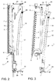
- the upper guide 17 extends in a generally horizontal plane from the first side 18 of the door system 1 (where the first door post 5 is arranged) towards the second side 19 of the door system 1 (where the second door post 6 is arranged), while coming closer to the entrance opening 4 and converging towards a plane that is substantially parallel to the entrance opening 4 ( Figure 2 ).
- An initial section 20 of the upper guide 17 (on the first side 18) defines with the entrance opening 4 an initial convergence angle ⁇ 20 of e.g. 36° (or from 25° to 45°..
- a final section 22 of the upper guide 17 (on the second side 19) defines with the entrance opening 4 a final convergence angle ⁇ 22 of e.g. 0° (or from 0° to 5°)
- an intermediate section 21 of the upper guide 17 between the initial section 20 and the final section 22 defines with the entrance opening 4 an intermediate convergence angle ⁇ 21 of e.g. 5° (or from 1° to 10°), wherein the intermediate convergence angle ⁇ 21 is smaller than the initial convergence angle ⁇ 20 and the final convergence angle ⁇ 22 is smaller than the intermediate convergence angle ⁇ 21.
- This configuration facilitates the initial outward rotation and the final inward counter-rotation of the door leaf 3.
- the upper guide 17 comprises preferably an overturned "U" profile, and may be engaged from below by an upper guide roller 25 or roller bearing connected, e.g. by a vertical post, with the suspension member 14.
- the first and second ends 11, 12 of the suspension rod 10 are slidably or rollably supported by corresponding first and second lateral guides 23, 24 which extend horizontally and transversally to the entrance opening 4.
- the lateral guides 23, 24 may have an angular or "C" shape profile, and may be each engaged by a lateral guide roller 26 or roller bearing of the first and second ends 11, 12 of the suspension rod 10.
- the second lateral guide 24 on the second side 19 may have a greater length than the first lateral guide 23 to enable the greater initial transverse outward movement of the door leaf 3 second side edge 9 with respect to the lesser initial movement of the door leaf 3 first side edge 8.
- the suspension member 14 may couple the suspension rod 10 and the door leaf 3 to the upper guide 17 in a manner that the upper guide 17 determines (only) the position of (a reference point of) the door leaf 3 in a horizontal suspension plane, but not also a rotational orientation of the door leaf 3 about a vertical axis with respect to the entrance opening 4.
- one or more auxiliary guides 27, 28 can be provided that slidingly constrain the door leaf 3 to the support structure 13 in a manner to determine, possibly together with the upper guide, also the rotational orientation of the door leaf 3 about a vertical axis with respect to the entrance opening 4, in each position of the suspension member 14 along the suspension rod 10.
- the suspension member 14 may slidingly couple the suspension rod 10 and the door leaf 3 to the upper guide 17 in a manner that the upper guide 17 determines the position of (a reference point of) the the door leaf 3 in a horizontal suspension plane, and also a rotational orientation of the door leaf 3 about a vertical axis with respect to the entrance opening 4.
- the precisely desired door movement can be easily adapted to the shape and space requirements of a specific application, such as a bus or a train wagon, by appropriately shaping the non-linear upper guide 17 and, possibly, the auxiliary guide/s 27, 28.
- a possibly required rotation of the door leaf 3 with respect to the suspension rod 10 can be achieved by a rotation hinge 29 (allowing rotation about a vertical axis, but blocking all relative translations) arranged between the door leaf 3 and the suspension member 14.
- This rotation hinge 29 can be situated in the door leaf 3 itself, in the suspension member 14 or in a supporting arm which connects the door leaf 3 to the suspension member 14.
- the first and second suspension points define the locations where a substantial part of or substantially all the weight of the door leaf 3 is transferred to the support structure 13 which in turn is mounted to the application, e.g. a passenger vehicle 2.
- the actuator 15 is supported by the support structure 13 and has a first actuator end 30 on the side of the first doorpost 5 and a second actuator end 31 on the side of the second doorpost 6, as well as an actuation slider 32 connected to the suspension member 14 and movable along the actuator 15 to pull or push the suspension member 14 along the suspension rod 10.
- connection between the actuation slider 32 and the suspension member 14 can be embodied by a hinged connecting rod 33 adapted to compensate variable relative positions between the actuation slider 32 and the suspension member 14.
- the actuator 15 may comprise a linear actuator, e.g. a pneumatic or hydraulic cylinder-piston group or a motor having a threaded rotor, wherein the motor housing or a member threaded on the rotor forms the actuator slider.
- a linear actuator e.g. a pneumatic or hydraulic cylinder-piston group or a motor having a threaded rotor, wherein the motor housing or a member threaded on the rotor forms the actuator slider.
- the displacement system 7 comprises a lever mechanism which is connected both to the first actuator end 30 and to an auxiliary guide system 27, 28 of the door leaf 3, and configured to push the door leaf 3 second side edge 9 transversally outward of and away from the entrance opening 4, in response to a backward movement of the first actuator end 30 opposite a forward movement of the actuator slider 32.
- Such a backward movement of the first actuator end 30 is brought about due to an initial resistance of the door leaf 3 against moving out of its closed position and the resulting backward reaction force between the actuation slider 32 and the first actuator end 30, which moves the latter backward until it reaches a stop position.
- the initial resistance of the door leaf 3 can be e.g. obtained by a curved initial blocking section 43 of the guide system, e.g. of the auxiliary guide/s 27, 28, the upper guide 17 or a further guide.
- the initial resistance can be obtained by an elastic spring force acting on the actuating slider 32 or by the inertial and frictional resistance of the door system 1.
- the actuating slider 32 continues its travel and carries the suspension member 14 along the suspension rod 10 and the door leaf 3 to the open position.
- the first actuator end 30 is connected to a first lever 34 which is movable around a first (vertical) rotation axis 35 (that is fixed with respect to the support structure 13 and on the first side 18 of the door system) at a distance from and transverse to a longitudinal axis 36 of the actuator 15, such that a longitudinal displacement of the first actuator end 30 results in a rotation of the first lever 34 around the first rotation axis 35.
- the first lever 34 is connected by a pull-push rod 37 to a second lever 38 which is movable around a second (vertical) rotation axis 39 (that is fixed with respect to the support structure 13 and on the second side 19 of the door system) at a distance from the first rotation axis 35, and wherein the second lever 38 is connected to an auxiliary guide system 27, 28 of the door leaf 3.
- a movement of the first actuator end 30 in a direction opposite the forward movement of the actuation slider 32 rotates the first 34 and second 38 levers such that the second lever 38 pushes the door leaf 3 second side edge 9 transversally outward of and away from the entrance opening 4.
- the auxiliary guide system 27, 28 of the door leaf 3 may comprise a lower auxiliary guide rail 27 and an upper auxiliary guide rail 28 arranged in or mounted to the door leaf 3, wherein the second lever 38 comprises a lower lever arm 40 that engages the lower auxiliary guide rail 27 and an upper lever arm 41 that engages the upper auxiliary guide rail 28.
- the guide system comprises one or more auxiliary guide rails 27, 28, arranged in the door leaf 3 or mounted to the door leaf 3 and engaged by one or more auxiliary guide rollers 42 or roller bearings connected to the support structure 13, preferably to the lever mechanism, more specifically to the second lever 38.
- the auxiliary guide rollers 42 may be engaged by the lower and/or upper auxiliary guide rail 27, 28 and by the second lever 38 in a manner to not only impose a translational position of the door leaf 3, but also a rotational orientation thereof.
- the movement trajectory of the door leaf 3 can be effectively defined with only little play.
- a curved initial blocking section 43 of the auxiliary guide rail 27, 28 near the second side edge 9 of the door leaf 3 is shaped in a manner that, during a displacement of the door leaf 3 into the closed position, the auxiliary guide roller/s 42 force the second side edge 9 of the door leaf 3 inward against the second doorpost 6.
- the present invention has been described as a door system 1 comprising at least one door leaf 3.
- the invention also relates to a door sub-system that coincides with the door system 1 described above, except that the door leaf 3 is lacking, and that the door sub-system is suitable for being mounted together with a door leaf 3.
- the invention relates also to a vehicle 2 comprising the door system 1.
Priority Applications (6)
| Application Number | Priority Date | Filing Date | Title |
|---|---|---|---|
| ES16159034T ES2748048T3 (es) | 2016-03-07 | 2016-03-07 | Sistema de puerta |
| SI201630384T SI3216957T1 (sl) | 2016-03-07 | 2016-03-07 | Sistem vrat |
| EP16159034.4A EP3216957B1 (fr) | 2016-03-07 | 2016-03-07 | Système de porte |
| PCT/IB2017/051312 WO2017153904A1 (fr) | 2016-03-07 | 2017-03-07 | Système de porte |
| US16/083,406 US10883295B2 (en) | 2016-03-07 | 2017-03-07 | Door system |
| RU2018131436A RU2731940C2 (ru) | 2016-03-07 | 2017-03-07 | Дверная система |
Applications Claiming Priority (1)
| Application Number | Priority Date | Filing Date | Title |
|---|---|---|---|
| EP16159034.4A EP3216957B1 (fr) | 2016-03-07 | 2016-03-07 | Système de porte |
Publications (2)
| Publication Number | Publication Date |
|---|---|
| EP3216957A1 true EP3216957A1 (fr) | 2017-09-13 |
| EP3216957B1 EP3216957B1 (fr) | 2019-07-03 |
Family
ID=55521561
Family Applications (1)
| Application Number | Title | Priority Date | Filing Date |
|---|---|---|---|
| EP16159034.4A Active EP3216957B1 (fr) | 2016-03-07 | 2016-03-07 | Système de porte |
Country Status (6)
| Country | Link |
|---|---|
| US (1) | US10883295B2 (fr) |
| EP (1) | EP3216957B1 (fr) |
| ES (1) | ES2748048T3 (fr) |
| RU (1) | RU2731940C2 (fr) |
| SI (1) | SI3216957T1 (fr) |
| WO (1) | WO2017153904A1 (fr) |
Citations (3)
| Publication number | Priority date | Publication date | Assignee | Title |
|---|---|---|---|---|
| EP0320591A2 (fr) * | 1987-12-12 | 1989-06-21 | Gebrüder Bode & Co. GmbH | Porte pivotante coulissante pour véhicules |
| EP1767427A1 (fr) * | 2005-09-23 | 2007-03-28 | Fahrzeugtechnik Dessau AG - Railroad Technologies - | Dispositif pour le mouvement d'un vantail de porte d'une porte pivotante coulissante, notamment pour véhicules ferroviaires |
| DE202013100356U1 (de) * | 2013-01-25 | 2014-04-28 | Gebr. Bode Gmbh & Co. Kg | Türanordnung mit Verriegelungssystem |
Family Cites Families (12)
| Publication number | Priority date | Publication date | Assignee | Title |
|---|---|---|---|---|
| DE3049189A1 (de) * | 1980-12-24 | 1982-07-29 | Gebr. Bode & Co, 3500 Kassel | Ausschwenkbare schiebetuer fuer fahrzeuge |
| NL9100951A (nl) * | 1991-06-03 | 1993-01-04 | Tbl Beheer Bv | Zwenkschuifdeurstelsel voor een voertuig. |
| DE4133179A1 (de) * | 1991-10-07 | 1993-04-08 | Bode & Co Geb | Vorrichtung zur bewegung einer schwenkschiebetuer fuer fahrzeuge zur personenbefoerderung, insbesondere schienenfahrzeuge |
| EP0589096B1 (fr) * | 1992-09-24 | 1996-12-27 | O.C.L.A.P. S.R.L. | Equipement pour portes coulissantes-louvoyantes pour véhicules de chemin de fer ou de voie de tramway |
| US5893236A (en) * | 1997-05-13 | 1999-04-13 | Westinghouse Air Brake Company | Power operator for sliding plug doors |
| US6282970B1 (en) * | 1998-09-28 | 2001-09-04 | Westinghouse Air Brake Company | Locking drive nut for screw drive systems |
| US6539669B1 (en) * | 2000-09-14 | 2003-04-01 | Westinghouse Air Brake Technologies Corporation | Plug door drive system |
| US6684567B2 (en) * | 2001-12-18 | 2004-02-03 | Westinghouse Air Brake Tecnologies Corporation | Plug door drive system |
| ITBL20030004A1 (it) * | 2003-04-09 | 2004-10-10 | Bortoluzzi Mobili S P A Ora Borto Luzzi Mobili S | Porte scorrevoli con guida a camma per chiusura complanare, |
| NL1031003C2 (nl) * | 2005-09-30 | 2007-04-02 | Nooijer Beheer B V De | Deursysteem, deursubsysteem en een voertuig voorzien van een deursysteem. |
| FR3003887B1 (fr) * | 2013-03-29 | 2015-07-03 | Faiveley Transp Tours | Dispositif de deplacement d'au moins un vantail de porte, vehicule ainsi pourvu et procede associe |
| EP2889200B1 (fr) * | 2013-12-30 | 2019-07-31 | Vapor Europe S.r.l. A Wabtec Company | Dispositif d'entraînement de porte pour porte de wagon |
-
2016
- 2016-03-07 ES ES16159034T patent/ES2748048T3/es active Active
- 2016-03-07 EP EP16159034.4A patent/EP3216957B1/fr active Active
- 2016-03-07 SI SI201630384T patent/SI3216957T1/sl unknown
-
2017
- 2017-03-07 RU RU2018131436A patent/RU2731940C2/ru active
- 2017-03-07 WO PCT/IB2017/051312 patent/WO2017153904A1/fr active Application Filing
- 2017-03-07 US US16/083,406 patent/US10883295B2/en active Active
Patent Citations (3)
| Publication number | Priority date | Publication date | Assignee | Title |
|---|---|---|---|---|
| EP0320591A2 (fr) * | 1987-12-12 | 1989-06-21 | Gebrüder Bode & Co. GmbH | Porte pivotante coulissante pour véhicules |
| EP1767427A1 (fr) * | 2005-09-23 | 2007-03-28 | Fahrzeugtechnik Dessau AG - Railroad Technologies - | Dispositif pour le mouvement d'un vantail de porte d'une porte pivotante coulissante, notamment pour véhicules ferroviaires |
| DE202013100356U1 (de) * | 2013-01-25 | 2014-04-28 | Gebr. Bode Gmbh & Co. Kg | Türanordnung mit Verriegelungssystem |
Also Published As
| Publication number | Publication date |
|---|---|
| US20190100952A1 (en) | 2019-04-04 |
| EP3216957B1 (fr) | 2019-07-03 |
| US10883295B2 (en) | 2021-01-05 |
| WO2017153904A1 (fr) | 2017-09-14 |
| RU2018131436A (ru) | 2020-04-08 |
| RU2018131436A3 (fr) | 2020-04-08 |
| ES2748048T3 (es) | 2020-03-12 |
| SI3216957T1 (sl) | 2019-12-31 |
| RU2731940C2 (ru) | 2020-09-09 |
Similar Documents
| Publication | Publication Date | Title |
|---|---|---|
| US8353555B2 (en) | Link-type sliding door mechanism | |
| US8336949B2 (en) | Link-type sliding door mechanism | |
| US7744035B2 (en) | Door for compartment of the baggage-compartment type | |
| CN101736982B (zh) | 用于车门的同步运动系统 | |
| KR100940896B1 (ko) | 도어 | |
| US20090007491A1 (en) | Pivotable Sliding Door | |
| US10792986B2 (en) | Arrangement with a cover for a vehicle roof | |
| SE517947C2 (sv) | Manövreringsmekanism för fordonsdörr | |
| US20150306942A1 (en) | Roof system for a motor vehicle | |
| EP2362046A1 (fr) | Mécanisme de porte coulissante | |
| JP2008511500A (ja) | 滑動式扉および衝撃の場合の滑動式扉の係留用手段を含む自動車 | |
| US10279819B2 (en) | Mounting for a front hatch of a car of a train and car of a train | |
| WO2013096248A1 (fr) | Ensemble rouleau supérieur pour une fermeture de véhicule coulissante | |
| US10883295B2 (en) | Door system | |
| JP4291224B2 (ja) | 車両用プラグドア装置 | |
| CN104302496A (zh) | 具有两个罩盖构件的车辆车顶 | |
| EP2263896B2 (fr) | Construction décapotable pour véhicule | |
| CN113382884B (zh) | 用于机动车的导流顶盖系统的驱动系统 | |
| EP1943405B1 (fr) | Systeme de porte et vehicule equipe d'un systeme de porte | |
| CN114845893A (zh) | 包括具有两个运动单元的车顶打开系统的车顶 | |
| US8894137B2 (en) | Open roof construction for a vehicle | |
| CN100554123C (zh) | 电梯装置 | |
| JP2017043350A (ja) | 自動車用スライドルーフシステム | |
| CN106985646B (zh) | 在汽车的可封闭的天窗部分上的挡风装置 | |
| RU134877U1 (ru) | Сдвижная дверь транспортного средства |
Legal Events
| Date | Code | Title | Description |
|---|---|---|---|
| PUAI | Public reference made under article 153(3) epc to a published international application that has entered the european phase |
Free format text: ORIGINAL CODE: 0009012 |
|
| STAA | Information on the status of an ep patent application or granted ep patent |
Free format text: STATUS: THE APPLICATION HAS BEEN PUBLISHED |
|
| AK | Designated contracting states |
Kind code of ref document: A1 Designated state(s): AL AT BE BG CH CY CZ DE DK EE ES FI FR GB GR HR HU IE IS IT LI LT LU LV MC MK MT NL NO PL PT RO RS SE SI SK SM TR |
|
| AX | Request for extension of the european patent |
Extension state: BA ME |
|
| TPAC | Observations filed by third parties |
Free format text: ORIGINAL CODE: EPIDOSNTIPA |
|
| STAA | Information on the status of an ep patent application or granted ep patent |
Free format text: STATUS: REQUEST FOR EXAMINATION WAS MADE |
|
| 17P | Request for examination filed |
Effective date: 20171215 |
|
| RBV | Designated contracting states (corrected) |
Designated state(s): AL AT BE BG CH CY CZ DE DK EE ES FI FR GB GR HR HU IE IS IT LI LT LU LV MC MK MT NL NO PL PT RO RS SE SI SK SM TR |
|
| STAA | Information on the status of an ep patent application or granted ep patent |
Free format text: STATUS: EXAMINATION IS IN PROGRESS |
|
| TPAC | Observations filed by third parties |
Free format text: ORIGINAL CODE: EPIDOSNTIPA |
|
| 17Q | First examination report despatched |
Effective date: 20180531 |
|
| GRAP | Despatch of communication of intention to grant a patent |
Free format text: ORIGINAL CODE: EPIDOSNIGR1 |
|
| STAA | Information on the status of an ep patent application or granted ep patent |
Free format text: STATUS: GRANT OF PATENT IS INTENDED |
|
| INTG | Intention to grant announced |
Effective date: 20190114 |
|
| GRAS | Grant fee paid |
Free format text: ORIGINAL CODE: EPIDOSNIGR3 |
|
| GRAA | (expected) grant |
Free format text: ORIGINAL CODE: 0009210 |
|
| STAA | Information on the status of an ep patent application or granted ep patent |
Free format text: STATUS: THE PATENT HAS BEEN GRANTED |
|
| AK | Designated contracting states |
Kind code of ref document: B1 Designated state(s): AL AT BE BG CH CY CZ DE DK EE ES FI FR GB GR HR HU IE IS IT LI LT LU LV MC MK MT NL NO PL PT RO RS SE SI SK SM TR |
|
| REG | Reference to a national code |
Ref country code: GB Ref legal event code: FG4D |
|
| REG | Reference to a national code |
Ref country code: CH Ref legal event code: EP Ref country code: AT Ref legal event code: REF Ref document number: 1151192 Country of ref document: AT Kind code of ref document: T Effective date: 20190715 |
|
| REG | Reference to a national code |
Ref country code: IE Ref legal event code: FG4D |
|
| REG | Reference to a national code |
Ref country code: DE Ref legal event code: R096 Ref document number: 602016016120 Country of ref document: DE |
|
| REG | Reference to a national code |
Ref country code: NL Ref legal event code: MP Effective date: 20190703 |
|
| REG | Reference to a national code |
Ref country code: LT Ref legal event code: MG4D |
|
| REG | Reference to a national code |
Ref country code: AT Ref legal event code: MK05 Ref document number: 1151192 Country of ref document: AT Kind code of ref document: T Effective date: 20190703 |
|
| PG25 | Lapsed in a contracting state [announced via postgrant information from national office to epo] |
Ref country code: AT Free format text: LAPSE BECAUSE OF FAILURE TO SUBMIT A TRANSLATION OF THE DESCRIPTION OR TO PAY THE FEE WITHIN THE PRESCRIBED TIME-LIMIT Effective date: 20190703 Ref country code: NL Free format text: LAPSE BECAUSE OF FAILURE TO SUBMIT A TRANSLATION OF THE DESCRIPTION OR TO PAY THE FEE WITHIN THE PRESCRIBED TIME-LIMIT Effective date: 20190703 Ref country code: BG Free format text: LAPSE BECAUSE OF FAILURE TO SUBMIT A TRANSLATION OF THE DESCRIPTION OR TO PAY THE FEE WITHIN THE PRESCRIBED TIME-LIMIT Effective date: 20191003 Ref country code: PT Free format text: LAPSE BECAUSE OF FAILURE TO SUBMIT A TRANSLATION OF THE DESCRIPTION OR TO PAY THE FEE WITHIN THE PRESCRIBED TIME-LIMIT Effective date: 20191104 Ref country code: SE Free format text: LAPSE BECAUSE OF FAILURE TO SUBMIT A TRANSLATION OF THE DESCRIPTION OR TO PAY THE FEE WITHIN THE PRESCRIBED TIME-LIMIT Effective date: 20190703 Ref country code: FI Free format text: LAPSE BECAUSE OF FAILURE TO SUBMIT A TRANSLATION OF THE DESCRIPTION OR TO PAY THE FEE WITHIN THE PRESCRIBED TIME-LIMIT Effective date: 20190703 Ref country code: NO Free format text: LAPSE BECAUSE OF FAILURE TO SUBMIT A TRANSLATION OF THE DESCRIPTION OR TO PAY THE FEE WITHIN THE PRESCRIBED TIME-LIMIT Effective date: 20191003 Ref country code: CZ Free format text: LAPSE BECAUSE OF FAILURE TO SUBMIT A TRANSLATION OF THE DESCRIPTION OR TO PAY THE FEE WITHIN THE PRESCRIBED TIME-LIMIT Effective date: 20190703 Ref country code: HR Free format text: LAPSE BECAUSE OF FAILURE TO SUBMIT A TRANSLATION OF THE DESCRIPTION OR TO PAY THE FEE WITHIN THE PRESCRIBED TIME-LIMIT Effective date: 20190703 Ref country code: LT Free format text: LAPSE BECAUSE OF FAILURE TO SUBMIT A TRANSLATION OF THE DESCRIPTION OR TO PAY THE FEE WITHIN THE PRESCRIBED TIME-LIMIT Effective date: 20190703 |
|
| PG25 | Lapsed in a contracting state [announced via postgrant information from national office to epo] |
Ref country code: LV Free format text: LAPSE BECAUSE OF FAILURE TO SUBMIT A TRANSLATION OF THE DESCRIPTION OR TO PAY THE FEE WITHIN THE PRESCRIBED TIME-LIMIT Effective date: 20190703 Ref country code: GR Free format text: LAPSE BECAUSE OF FAILURE TO SUBMIT A TRANSLATION OF THE DESCRIPTION OR TO PAY THE FEE WITHIN THE PRESCRIBED TIME-LIMIT Effective date: 20191004 Ref country code: IS Free format text: LAPSE BECAUSE OF FAILURE TO SUBMIT A TRANSLATION OF THE DESCRIPTION OR TO PAY THE FEE WITHIN THE PRESCRIBED TIME-LIMIT Effective date: 20191103 Ref country code: RS Free format text: LAPSE BECAUSE OF FAILURE TO SUBMIT A TRANSLATION OF THE DESCRIPTION OR TO PAY THE FEE WITHIN THE PRESCRIBED TIME-LIMIT Effective date: 20190703 Ref country code: AL Free format text: LAPSE BECAUSE OF FAILURE TO SUBMIT A TRANSLATION OF THE DESCRIPTION OR TO PAY THE FEE WITHIN THE PRESCRIBED TIME-LIMIT Effective date: 20190703 |
|
| REG | Reference to a national code |
Ref country code: ES Ref legal event code: FG2A Ref document number: 2748048 Country of ref document: ES Kind code of ref document: T3 Effective date: 20200312 |
|
| PG25 | Lapsed in a contracting state [announced via postgrant information from national office to epo] |
Ref country code: TR Free format text: LAPSE BECAUSE OF FAILURE TO SUBMIT A TRANSLATION OF THE DESCRIPTION OR TO PAY THE FEE WITHIN THE PRESCRIBED TIME-LIMIT Effective date: 20190703 |
|
| PG25 | Lapsed in a contracting state [announced via postgrant information from national office to epo] |
Ref country code: DK Free format text: LAPSE BECAUSE OF FAILURE TO SUBMIT A TRANSLATION OF THE DESCRIPTION OR TO PAY THE FEE WITHIN THE PRESCRIBED TIME-LIMIT Effective date: 20190703 Ref country code: PL Free format text: LAPSE BECAUSE OF FAILURE TO SUBMIT A TRANSLATION OF THE DESCRIPTION OR TO PAY THE FEE WITHIN THE PRESCRIBED TIME-LIMIT Effective date: 20190703 Ref country code: EE Free format text: LAPSE BECAUSE OF FAILURE TO SUBMIT A TRANSLATION OF THE DESCRIPTION OR TO PAY THE FEE WITHIN THE PRESCRIBED TIME-LIMIT Effective date: 20190703 Ref country code: RO Free format text: LAPSE BECAUSE OF FAILURE TO SUBMIT A TRANSLATION OF THE DESCRIPTION OR TO PAY THE FEE WITHIN THE PRESCRIBED TIME-LIMIT Effective date: 20190703 |
|
| PG25 | Lapsed in a contracting state [announced via postgrant information from national office to epo] |
Ref country code: SM Free format text: LAPSE BECAUSE OF FAILURE TO SUBMIT A TRANSLATION OF THE DESCRIPTION OR TO PAY THE FEE WITHIN THE PRESCRIBED TIME-LIMIT Effective date: 20190703 Ref country code: IS Free format text: LAPSE BECAUSE OF FAILURE TO SUBMIT A TRANSLATION OF THE DESCRIPTION OR TO PAY THE FEE WITHIN THE PRESCRIBED TIME-LIMIT Effective date: 20200224 Ref country code: SK Free format text: LAPSE BECAUSE OF FAILURE TO SUBMIT A TRANSLATION OF THE DESCRIPTION OR TO PAY THE FEE WITHIN THE PRESCRIBED TIME-LIMIT Effective date: 20190703 |
|
| REG | Reference to a national code |
Ref country code: DE Ref legal event code: R097 Ref document number: 602016016120 Country of ref document: DE |
|
| PLBE | No opposition filed within time limit |
Free format text: ORIGINAL CODE: 0009261 |
|
| STAA | Information on the status of an ep patent application or granted ep patent |
Free format text: STATUS: NO OPPOSITION FILED WITHIN TIME LIMIT |
|
| PG2D | Information on lapse in contracting state deleted |
Ref country code: IS |
|
| 26N | No opposition filed |
Effective date: 20200603 |
|
| REG | Reference to a national code |
Ref country code: DE Ref legal event code: R119 Ref document number: 602016016120 Country of ref document: DE |
|
| PG25 | Lapsed in a contracting state [announced via postgrant information from national office to epo] |
Ref country code: MC Free format text: LAPSE BECAUSE OF FAILURE TO SUBMIT A TRANSLATION OF THE DESCRIPTION OR TO PAY THE FEE WITHIN THE PRESCRIBED TIME-LIMIT Effective date: 20190703 |
|
| REG | Reference to a national code |
Ref country code: CH Ref legal event code: PL |
|
| REG | Reference to a national code |
Ref country code: BE Ref legal event code: MM Effective date: 20200331 |
|
| PG25 | Lapsed in a contracting state [announced via postgrant information from national office to epo] |
Ref country code: LU Free format text: LAPSE BECAUSE OF NON-PAYMENT OF DUE FEES Effective date: 20200307 |
|
| PG25 | Lapsed in a contracting state [announced via postgrant information from national office to epo] |
Ref country code: LI Free format text: LAPSE BECAUSE OF NON-PAYMENT OF DUE FEES Effective date: 20200331 Ref country code: DE Free format text: LAPSE BECAUSE OF NON-PAYMENT OF DUE FEES Effective date: 20201001 Ref country code: CH Free format text: LAPSE BECAUSE OF NON-PAYMENT OF DUE FEES Effective date: 20200331 Ref country code: IE Free format text: LAPSE BECAUSE OF NON-PAYMENT OF DUE FEES Effective date: 20200307 Ref country code: FR Free format text: LAPSE BECAUSE OF NON-PAYMENT OF DUE FEES Effective date: 20200331 |
|
| PG25 | Lapsed in a contracting state [announced via postgrant information from national office to epo] |
Ref country code: BE Free format text: LAPSE BECAUSE OF NON-PAYMENT OF DUE FEES Effective date: 20200331 |
|
| GBPC | Gb: european patent ceased through non-payment of renewal fee |
Effective date: 20200307 |
|
| PG25 | Lapsed in a contracting state [announced via postgrant information from national office to epo] |
Ref country code: GB Free format text: LAPSE BECAUSE OF NON-PAYMENT OF DUE FEES Effective date: 20200307 |
|
| PG25 | Lapsed in a contracting state [announced via postgrant information from national office to epo] |
Ref country code: MT Free format text: LAPSE BECAUSE OF FAILURE TO SUBMIT A TRANSLATION OF THE DESCRIPTION OR TO PAY THE FEE WITHIN THE PRESCRIBED TIME-LIMIT Effective date: 20190703 Ref country code: CY Free format text: LAPSE BECAUSE OF FAILURE TO SUBMIT A TRANSLATION OF THE DESCRIPTION OR TO PAY THE FEE WITHIN THE PRESCRIBED TIME-LIMIT Effective date: 20190703 |
|
| PG25 | Lapsed in a contracting state [announced via postgrant information from national office to epo] |
Ref country code: MK Free format text: LAPSE BECAUSE OF FAILURE TO SUBMIT A TRANSLATION OF THE DESCRIPTION OR TO PAY THE FEE WITHIN THE PRESCRIBED TIME-LIMIT Effective date: 20190703 |
|
| PGFP | Annual fee paid to national office [announced via postgrant information from national office to epo] |
Ref country code: SI Payment date: 20220303 Year of fee payment: 7 |
|
| PGFP | Annual fee paid to national office [announced via postgrant information from national office to epo] |
Ref country code: IT Payment date: 20230216 Year of fee payment: 8 |
|
| PGFP | Annual fee paid to national office [announced via postgrant information from national office to epo] |
Ref country code: ES Payment date: 20230403 Year of fee payment: 8 |
|
| REG | Reference to a national code |
Ref country code: SI Ref legal event code: KO00 Effective date: 20231127 |
|
| PG25 | Lapsed in a contracting state [announced via postgrant information from national office to epo] |
Ref country code: SI Free format text: LAPSE BECAUSE OF NON-PAYMENT OF DUE FEES Effective date: 20230308 |