EP3216532A1 - Sicherheitsverschluss für einen behälter mit einer medienzufuhrleitung - Google Patents
Sicherheitsverschluss für einen behälter mit einer medienzufuhrleitung Download PDFInfo
- Publication number
- EP3216532A1 EP3216532A1 EP16204449.9A EP16204449A EP3216532A1 EP 3216532 A1 EP3216532 A1 EP 3216532A1 EP 16204449 A EP16204449 A EP 16204449A EP 3216532 A1 EP3216532 A1 EP 3216532A1
- Authority
- EP
- European Patent Office
- Prior art keywords
- locking element
- container
- lid
- obturator
- supply line
- Prior art date
- Legal status (The legal status is an assumption and is not a legal conclusion. Google has not performed a legal analysis and makes no representation as to the accuracy of the status listed.)
- Granted
Links
Images

Classifications
-
- B—PERFORMING OPERATIONS; TRANSPORTING
- B65—CONVEYING; PACKING; STORING; HANDLING THIN OR FILAMENTARY MATERIAL
- B65D—CONTAINERS FOR STORAGE OR TRANSPORT OF ARTICLES OR MATERIALS, e.g. BAGS, BARRELS, BOTTLES, BOXES, CANS, CARTONS, CRATES, DRUMS, JARS, TANKS, HOPPERS, FORWARDING CONTAINERS; ACCESSORIES, CLOSURES, OR FITTINGS THEREFOR; PACKAGING ELEMENTS; PACKAGES
- B65D90/00—Component parts, details or accessories for large containers
-
- B—PERFORMING OPERATIONS; TRANSPORTING
- B65—CONVEYING; PACKING; STORING; HANDLING THIN OR FILAMENTARY MATERIAL
- B65D—CONTAINERS FOR STORAGE OR TRANSPORT OF ARTICLES OR MATERIALS, e.g. BAGS, BARRELS, BOTTLES, BOXES, CANS, CARTONS, CRATES, DRUMS, JARS, TANKS, HOPPERS, FORWARDING CONTAINERS; ACCESSORIES, CLOSURES, OR FITTINGS THEREFOR; PACKAGING ELEMENTS; PACKAGES
- B65D43/00—Lids or covers for rigid or semi-rigid containers
- B65D43/26—Mechanisms for opening or closing, e.g. pedal-operated
- B65D43/267—Mechanisms for opening or closing, e.g. pedal-operated consisting of levers pivoting radially to container axis
-
- B—PERFORMING OPERATIONS; TRANSPORTING
- B05—SPRAYING OR ATOMISING IN GENERAL; APPLYING FLUENT MATERIALS TO SURFACES, IN GENERAL
- B05B—SPRAYING APPARATUS; ATOMISING APPARATUS; NOZZLES
- B05B12/00—Arrangements for controlling delivery; Arrangements for controlling the spray area
- B05B12/14—Arrangements for controlling delivery; Arrangements for controlling the spray area for supplying a selected one of a plurality of liquids or other fluent materials or several in selected proportions to a spray apparatus, e.g. to a single spray outlet
-
- B—PERFORMING OPERATIONS; TRANSPORTING
- B08—CLEANING
- B08B—CLEANING IN GENERAL; PREVENTION OF FOULING IN GENERAL
- B08B3/00—Cleaning by methods involving the use or presence of liquid or steam
- B08B3/006—Cabinets or cupboards specially adapted for cleaning articles by hand
-
- B—PERFORMING OPERATIONS; TRANSPORTING
- B08—CLEANING
- B08B—CLEANING IN GENERAL; PREVENTION OF FOULING IN GENERAL
- B08B9/00—Cleaning hollow articles by methods or apparatus specially adapted thereto
- B08B9/08—Cleaning containers, e.g. tanks
-
- B—PERFORMING OPERATIONS; TRANSPORTING
- B08—CLEANING
- B08B—CLEANING IN GENERAL; PREVENTION OF FOULING IN GENERAL
- B08B9/00—Cleaning hollow articles by methods or apparatus specially adapted thereto
- B08B9/08—Cleaning containers, e.g. tanks
- B08B9/0804—Cleaning containers having tubular shape, e.g. casks, barrels, drums
- B08B9/0813—Cleaning containers having tubular shape, e.g. casks, barrels, drums by the force of jets or sprays
-
- B—PERFORMING OPERATIONS; TRANSPORTING
- B08—CLEANING
- B08B—CLEANING IN GENERAL; PREVENTION OF FOULING IN GENERAL
- B08B9/00—Cleaning hollow articles by methods or apparatus specially adapted thereto
- B08B9/08—Cleaning containers, e.g. tanks
- B08B9/093—Cleaning containers, e.g. tanks by the force of jets or sprays
-
- B—PERFORMING OPERATIONS; TRANSPORTING
- B65—CONVEYING; PACKING; STORING; HANDLING THIN OR FILAMENTARY MATERIAL
- B65D—CONTAINERS FOR STORAGE OR TRANSPORT OF ARTICLES OR MATERIALS, e.g. BAGS, BARRELS, BOTTLES, BOXES, CANS, CARTONS, CRATES, DRUMS, JARS, TANKS, HOPPERS, FORWARDING CONTAINERS; ACCESSORIES, CLOSURES, OR FITTINGS THEREFOR; PACKAGING ELEMENTS; PACKAGES
- B65D55/00—Accessories for container closures not otherwise provided for
- B65D55/02—Locking devices; Means for discouraging or indicating unauthorised opening or removal of closure
-
- B—PERFORMING OPERATIONS; TRANSPORTING
- B65—CONVEYING; PACKING; STORING; HANDLING THIN OR FILAMENTARY MATERIAL
- B65D—CONTAINERS FOR STORAGE OR TRANSPORT OF ARTICLES OR MATERIALS, e.g. BAGS, BARRELS, BOTTLES, BOXES, CANS, CARTONS, CRATES, DRUMS, JARS, TANKS, HOPPERS, FORWARDING CONTAINERS; ACCESSORIES, CLOSURES, OR FITTINGS THEREFOR; PACKAGING ELEMENTS; PACKAGES
- B65D90/00—Component parts, details or accessories for large containers
- B65D90/22—Safety features
-
- B—PERFORMING OPERATIONS; TRANSPORTING
- B65—CONVEYING; PACKING; STORING; HANDLING THIN OR FILAMENTARY MATERIAL
- B65D—CONTAINERS FOR STORAGE OR TRANSPORT OF ARTICLES OR MATERIALS, e.g. BAGS, BARRELS, BOTTLES, BOXES, CANS, CARTONS, CRATES, DRUMS, JARS, TANKS, HOPPERS, FORWARDING CONTAINERS; ACCESSORIES, CLOSURES, OR FITTINGS THEREFOR; PACKAGING ELEMENTS; PACKAGES
- B65D90/00—Component parts, details or accessories for large containers
- B65D90/54—Gates or closures
Definitions
- the invention relates to a safety closure for a container with a media supply line, in particular cleaning line, and a correspondingly secured container, in particular dosing container.
- Safety devices known from the prior art are usually designed electrically.
- sensors that record the opening state of the lid such as from the WO 2013/079746 A1 known and electrical signal transmission can be a faulty opening controllable shut-off valves in feeding lines recognize.
- signals from the door switch can be transferred to programmable logic controllers to prevent inadvertent opening of incoming shut-off valves by appropriate signal processing.
- the unintentional opening of incoming shut-off devices can also be prevented by means of electrical hardware wiring.
- padlocks are also used for purely mechanical protection. However, these only ensure the authenticity of the key in the hands of the operator, but offer no protection against incorrect operation.
- a security closure according to WO 2013/079746 A1 be formed substantially in two stages to allow first a pressure relief or the like by limited opening and thus to prevent uncontrolled opening of the lid.
- an electric door switch is also used in this context.
- the security closure is designed for or on a container with a media supply line.
- the container is in particular a dosing container.
- the media supply line is preferably used for ejecting the container, in particular for cleaning such as the CIP (Cleaning-In-Place) method.
- the safety closure comprises: a lid, in particular mechanically operable, for closing the container; a shut-off device for closing the media supply line; a pivoting lever with an actuating arm for placing the lid on the container and with a particular opposite first locking element; and a second locking element, which is drive-coupled to the obturator and which is configured as a stop for the first locking element that is selectively effective when the obturator is open in such a way that the cover can not be opened.
- the unopened lid acts as a splash guard from the inside of the container to the outside.
- operators are protected from scalding and / or chemical burns when spraying the container with liquid medium and / or disinfectants, which could otherwise escape with the lid open and the obturator open.
- the first locking element is for example a lever arm or a disc.
- the second locking element is designed such that it mechanically blocks the first locking element when the obturator is open, thereby preventing lifting of the cover as far as possible, that a splash guard is given.
- the pivoting lever is preferably rotatably mounted between the actuating arm and the first locking element, in particular about a horizontal tilting axis.
- the actuating arm is preferably connected to the lid, for example by a hinge. As a result, the lid can be lifted hanging on the actuating arm. However, it is also conceivable releasable from the lid actuating arm which engages for closing, for example, in a groove formed in the lid.
- the obturator is preferably a disc valve, in particular a manually operated hand flap. Furthermore, other functionally appropriate shut-off valves, such as a ball valve or the like, can be used.
- the second locking element is preferably fixedly connected to the obturator, for example by positive engagement with a trained on the obturator handle.
- the second locking element is further configured such that the first locking element blocks the obturator with the lid open in a closed position by means of the second locking element.
- the second locking element is designed such that it releases the first locking element only when the shut-off element is closed.
- the lid can only be opened when the shut-off device is closed. Accordingly, the obturator can only be opened when the lid is closed.
- Container and lid are formed, and in particular dimensioned so that the unlocked lid can be opened manually, in particular to fill a product component and / or a product additive.
- the second locking element has a recess which is aligned with the shut-off element closed with the first locking element, such that the first locking element tilts when opening the lid into the recess.
- the shift lever then engages positively with the lid open in the recess and prevents opening of the obturator.
- the second locking element is a locking disc with a recess for the first locking element.
- the locking disc can be firmly connected or coupled by means of a transmission in a simple way to the obturator.
- the recess allows a simple apparatus and reliable positive connection with the first locking element.
- the first locking element has a recess for the second locking element.
- the first locking element is then designed in particular as a disk and pivotable together with the cover about a vertical axis of rotation.
- the second locking element engages positively in the recess of the first locking element and thereby acts as a mechanically blocking stop for the first locking element, which prevents the lid from opening.
- the first locking element for opening the lid can only be swiveled / rotated into the recess of the second locking element when the obturator is closed.
- the second locking element is movable about an axis of rotation which is aligned orthogonal to a pivot axis of the pivot lever. This allows a simple switching between a stop of the first locking element against the second locking element and a positive engagement of the first locking element in the recess of the second locking element.
- the obturator can be manually opened / closed by means of an actuating lever.
- the second locking element is then firmly connected to the actuating lever. This allows a particularly reliable and simple securing of the closed lid or obturator by means of mechanical locking, in particular without electrical or pneumatic actuators.
- the container is a dosage container.
- the lid is then designed to close a filling opening for a product component.
- Such containers are suitable for conventional capacity especially for a manual / mechanical operation and securing the lid.
- an ejection device for the container is connected to the media supply line.
- the ejection device comprises, for example, a pump and / or a pressurized supply line for a liquid medium and at least one ejection nozzle in the interior of the container. This allows efficient rinsing and / or cleaning in the sense of a CIP.
- an electrically or pneumatically actuated valve for shutting off / releasing the media supply line is additionally present.
- This valve is used for the centrally controlled supply of exemplary cleaning agents and / or water and is then formed in series with the mechanical obturator of the safety closure, in particular upstream of it. This allows a central control of cleaning processes without affecting the process flow through the protection by means of the mechanical obturator.
- the pivot lever is rotatably mounted laterally of the lid on the container.
- the actuating arm of the pivot lever then engages over the lid.
- the first locking element can then be arranged in a simple manner opposite to the actuating arm and extend into the region of the second locking element.
- the pivot lever is, for example, mounted rotatably about a horizontal or vertical pivot axis on a bearing block.
- the bearing block may be formed on the container or, for example, be attached to the media supply line.
- the security fastener further comprises a latch for the actuating arm secured to the container in a position of the lid sealing the container.
- the lock can be designed, for example, pivotable, in particular about a horizontal axis of rotation to release the actuating arm for a complete opening of the lid.
- the actuating arm for a sealing pressing of the lid on the container can be mechanically relieved.
- the lid is designed for manual opening / closing.
- a container which is designed as a dosing container for a product component or a product additive, in particular for the production of a beverage, with a media supply line and a safety closure according to at least one of the embodiments described above.
- Product components include hops / hop products, color beer, flavors and raw materials.
- Product additives are, for example, enzymes, lactic acid, mineral acid and filter aids.
- the container is then designed for stationary operation in a production facility for foods, such as drinks and beer in particular, and the media supply line for rinsing and / or cleaning without disassembly of the dosing container in the sense of a CIP.
- the production plant can be installed, for example, in a brewhouse or in a cold area of a brewery.
- the container can in principle be mobile, in particular mobile, and be connected by means of hoses or the like lines to a corresponding production plant.
- the container is designed as hop hopper.
- the safety closure can be used particularly advantageously on such a container, as well as on other containers for brewing additives.
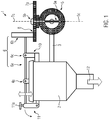
- the safety closure 1 is formed according to a first preferred embodiment of a container 2 with a media supply line 3 for rinsing and / or cleaning the container 2.
- the safety closure 1 comprises: a vertically tiltable lid 4 for manually closing the container 2; a shut-off device 5 for manually closing the media supply line 3; a pivoting lever 6 with an actuating arm 6a for placing the lid 4 and with an opposite first locking element 6b; and a second locking member 7 drivingly coupled to the obturator 5, which either blocks or releases movement of the first locking member 6b to unlock the cover 4.
- the first locking element 6b is designed, for example, as a lever arm, disk segment or the like.
- the pivot lever 6 is rotatably mounted about a preferably horizontal pivot axis 6c.
- the second locking element 7 is preferably designed to be rotatable as a locking disk 7a with a recess 7b about a vertical axis of rotation 7c.
- the obturator 5 is preferably designed as a hand flap, so as a disc valve with a flap 5a and a handle 5b for manual opening / closing. This is schematically indicated in the figure 2 as a double arrow, the actuating directions are merely exemplary.
- the flap 5a is rotatably mounted in the obturator 5 for closing the obturator 5 about a rotation axis 5c.
- the axes of rotation 5c, 7c are preferably identical for a direct coupling of the locking disc 7a and the flap 5a to each other.
- Other shut-off devices are conceivable, which can be actuated by rotational movement about an axis. From the FIG. 1 It is clear that the second locking element 7, in particular the locking disc 7a, as a selectively effective with open obturator 5 stop 8 is formed for the first locking element 6b, so that the lid 4 can not open when the obturator 5 is open.
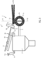
- the first locking element 6b can only tilt when the obturator 5 is closed in / through the recess 7b, and indeed if the first locking element 6b in plan view (the FIG. 2 ) is aligned with the recess 7b, so the locking disc 7a rests in a corresponding rotational position. This allows opening the lid 4, which also blocks the obturator 5 in its closed position.
- the aligned with the first locking element 6b position 9 of the recess 7b and the corresponding position of the handle 5b are in the FIG. 2 for better understanding indicated by dotted lines.
- the bearing block 10 may also be attached to, for example, a pipeline such as the media supply line 3
- a detent 11 for the closed lid 4 is preferably further formed on the container 2, a detent 11 for the closed lid 4 is preferably further formed.
- the lock 11 may include a locking screw 11 a or the like and, for example, about a horizontal axis of rotation 11 b to be pivoted to release the operating lever 6 a for opening the lid 4 after loosening the locking screw 11 a.
- the lid 4 preferably comprises a holder 4a, on which the lid 4 hangs on the actuating lever 6a.
- the cover 4 is preferably rotationally fixed or tiltable about a horizontal axis of rotation mounted on the actuating lever 6a.
- the lid 4 can be placed on the container 2 by means of the actuating lever 6a and lifted off this.
- the container 2 is preferably designed as a dosing container.
- the cover 4 When the cover 4 is open can be a (in the FIG. 1 by a block arrow schematically indicated) product component 12, a product additive or the like in the container 2 fill.
- the container 2 When the cover 4 is closed, the container 2 can be rinsed, cleaned and, in particular, sprayed through the media supply line 3 with a liquid medium 13, such as hot water, for example.
- a liquid medium 13 such as hot water, for example.
- at least one ejection device 14 is preferably provided on the media supply line 3, for example in the form of a spray nozzle (shown) and / or a pump (not shown) and / or the like means for supplying the liquid medium 13 under a suitable overpressure.
- the liquid medium may in principle include a rinsing agent, cleaning agent, disinfectant, at least one technical auxiliary and / or product.
- Engineering auxiliaries can also be counted among the product additives and include, for example, enzymes, calcium chloride, acid and solvents other than water.
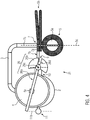
- the security closure 21 may be formed according to a second preferred embodiment alternatively for a about a vertical pivot axis 26c pivotable pivot lever 26 and cover 4.
- the pivoting lever 26 comprises an actuating arm 26a, which is preferably fixedly connected to the cover 4 by the holder 4a, and a first locking element 26b, which interacts with the second locking element 7 functionally as in the first embodiment.
- the first locking element 26b is then preferably disk-shaped with a recess 26d, for example a notch.
- the lid 4 can only be opened if the recess 7b of the locking disc 7a is aligned with respect to the first locking element 6b, 26b such that it can pivot into or rotate into the recess 7b. Otherwise, the locking disc 7a acts as a stop 8 for the first locking element 6b, 26b to prevent opening of the lid 4.
- the obturator 5 can only be opened when the recess 26d of the first locking element 26b is aligned with the second locking element 7, in particular with the locking disc 7a.
- the pivot axes 6c, 26c are preferably oriented orthogonally to the axis of rotation 7c of the locking disc 7a.
- the safety lock 1, 21 is constructed purely mechanically and therefore has a particularly high reliability. Accordingly, the safety closure 1, 21 can serve as an additional safety measure, which is indeed redundant in the trouble-free operation of the optional electrically and / or pneumatically operated valve 15, due to the serial arrangement of the obturator 5 and the valve 15, however, for example in the event of a seal break in the valve 15, So even with its perfect control and / or position, comes into play.
- the second locking element 7 is preferably connected rotationally fixed both with the flap 5a and with the handle 5b, for example by positive locking. It would also be conceivable, however, to couple the second locking element 7 to the obturator 5 by means of a gear mechanism, a link, a worm drive, gearwheel / toothed rack or the like.
- the position of the recess 7b with respect to the first locking element 6b, 26b changes depending on the opening position of the obturator 5 as described above, ie the second locking element 7, optionally also in the form of a control slide, with open obturator 5 as a stop. 8 acts for the first locking element 6b, 26b and the recess 7b of the second locking element 7 is in closed obturator 5 in a aligned with the first locking element 6b, 26b position 9, so that the first locking element 6b, 26b can pivot into the recess 7b.
- the container 2 and the media supply line 3 are suitable for stationary installation and irrigation and / or cleaning and / or disinfection in a food-processing operation, such as in a brewhouse or similar production plant.
- the safety closure 1, 21 ensures in a simple and reliable manner a protection of operating personnel from hot and / or aggressive liquid media 13, which could otherwise escape due to accidental opening of the lid 4, in particular during a flushing and / or cleaning and / or disinfection. Disinfection also means sterilization. The same applies to disinfectants and disinfectants.
- the ejection device 14 can be understood, for example, as a pipeline which ends in the container 2.
- the ejection device 14 may comprise distribution devices, such as spray head, jet cleaner, baffle plates or similar devices, which distribute or fan out the medium. Also ring lines with openings are conceivable.
Landscapes
- Engineering & Computer Science (AREA)
- Mechanical Engineering (AREA)
- Closures For Containers (AREA)
Abstract
Description
- Die Erfindung betrifft einen Sicherheitsverschluss für einen Behälter mit einer Medienzufuhrleitung, insbesondere Reinigungsleitung, und einen entsprechend gesicherten Behälter, insbesondere Dosierungsbehälter.
- Gängige Sicherheitsanforderungen gemäß Maschinenrichtlinie erfordern für in Produktionsanlagen integrierte Behälter mit manuell zu öffnenden Deckeln und mit einer Medienzufuhrleitung zum Reinigen, insbesondere Ausspritzen des Behälters, für eine Heißwasserzufuhr oder dergleichen geeignete technische Maßnahmen zur Vermeidung von Personenschäden aufgrund von Fehlbedienungen. Diese drohen prinzipiell, falls Behälter während einer Zufuhr von Heißwasser, aggressiven Reinigungsmitteln oder dergleichen Medien geöffnet werden. Besondere Gefahr geht dabei von Spritzköpfen aus, die zum Beispiel Heißwasser oder Reinigungsmittel unter Druck großflächig verteilen.
- In der Lebensmittelindustrie, insbesondere in der Getränkeindustrie, ist diese Problematik vor allem bei Behältern zum Dosieren von Kleinmengen anzutreffen, wie beispielsweise in einer Brauerei bei Hopfengabebehältern, Additivbehältern oder allgemein bei Behältern zur Dosierung von Zusätzen beim Brauen. Prinzipiell gilt dies jedoch für alle Behälter, bei denen eine Handhabung der Deckel im Handbetrieb praktikabel ist.
- Aus dem Stand der Technik bekannte Sicherheitsvorrichtungen sind meistens elektrisch ausgeführt. Mittels Sensoren, die den Öffnungszustand des Deckels aufnehmen, wie beispielsweise aus der
WO 2013/079746 A1 bekannt, und elektrischer Signalübertragung lässt sich ein fehlerhaftes Öffnen steuerbarer Absperrarmaturen in zuführenden Leitungen erkennen. Zusätzlich können Signale vom Türschalter in speicherprogrammierbare Anlagensteuerungen übertragen werden, um darin ein unbeabsichtigtes Öffnen zuführender Absperrorgane durch geeignete Signalverarbeitung zu verhindern. Das unbeabsichtigte Öffnen zuführender Absperrorgane kann auch mittels elektrischer Hardwareverdrahtung verhindert werden. - Eine elektrisch gesteuerte Deckelsicherung ist jedoch aufwändig wegen der notwendigen Hardware, Softwareprogrammierung und einer vergleichsweise aufwändigen Inbetriebnahme.
- Außerdem bedarf es bei einer derartigen elektrischen Deckelsicherung einer einwandfreien Funktion der gesamten Steuerstrecke, einschließlich Türschalter, diversen Signalleitungen, der zentralen Steuereinheit und gegebenenfalls vorhandener elektrisch angesteuerter Vorsteuereinrichtungen für pneumatisch gesteuerte Absperrorgane. Die Ausfallwahrscheinlichkeit einzelner Komponenten summiert sich dabei auf. Sicherheitstechnisch problematisch können zudem Schnittstellen zwischen Anlagenteilen unterschiedlicher Lieferanten sein.
- Alternativ zur elektrischen Deckelsicherung werden auch Vorhängeschlösser zur rein mechanischen Absicherung verwendet. Diese stellen jedoch lediglich die Authentizität des Schlüssels in der Hand des Bedieners sicher, bieten aber keinen Schutz vor Fehlbedienung.
- Alternativ kann ein Sicherheitsverschluss gemäß
WO 2013/079746 A1 im Wesentlichen zweistufig ausgebildet sein, um zuerst eine Druckentlastung oder dergleichen durch begrenztes Öffnen zu ermöglichen und so ein unkontrolliertes Aufschlagen des Deckels zu verhindern. Allerdings wird auch in diesem Zusammenhang ein elektrischer Türschalter ergänzend eingesetzt. - Es besteht somit Bedarf für einen zuverlässigen und apparativ einfachen Sicherheitsverschluss, der ein unkontrolliertes und/oder versehentliches und/oder fehlerhaftes Öffnen eines mechanisch zu betätigenden Deckels an einem Behälter mit einer Medienzufuhrleitung für sicherheitstechnisch relevante Medien, wie beispielsweise Reinigungslösungen, verhindert.
- Die gestellte Aufgabe wird mit einem Sicherheitsverschluss nach Anspruch 1 gelöst. Demnach ist der Sicherheitsverschluss für einen bzw. an einem Behälter mit einer Medienzufuhrleitung ausgebildet. Der Behälter ist insbesondere ein Dosierungsbehälter. Die Medienzufuhrleitung dient vorzugsweise zum Ausspritzen des Behälters, insbesondere zur Reinigung wie etwa dem CIP (Cleaning-In-Place) Verfahren.
- Der Sicherheitsverschluss umfasst: einen insbesondere mechanisch zu betätigenden Deckel zum Verschließen des Behälters; ein Absperrorgan zum Verschließen der Medienzufuhrleitung; einen Schwenkhebel mit einem Betätigungsarm zum Aufsetzen des Deckels auf den Behälter und mit einem insbesondere entgegengesetzten ersten Verriegelungselement; und ein mit dem Absperrorgan antriebstechnisch gekoppeltes zweites Verriegelungselement, das als ein selektiv bei geöffnetem Absperrorgan wirksamer Anschlag für das erste Verriegelungselement derart ausgebildet ist, dass der Deckel nicht geöffnet werden kann.
- Darunter ist zu verstehen, dass der nicht geöffnete Deckel als Spritzschutz vom Inneren des Behälters nach außen hin wirkt. Dadurch werden Bediener vor Verbrühungen und/oder Verätzungen beim Ausspritzen des Behälters mit Flüssigmedium und/oder Desinfektionsmitteln geschützt, die ansonsten bei geöffnetem Deckel und geöffnetem Absperrorgan austreten könnten.
- Das erste Verriegelungselement ist beispielsweise ein Hebelarm oder eine Scheibe. Das zweite Verriegelungselement ist derart ausgebildet, dass es das erste Verriegelungselement bei geöffnetem Absperrorgan mechanisch blockiert und dadurch ein Abheben des Deckels soweit verhindert, dass ein Spritzschutz gegeben ist. Der Schwenkhebel ist vorzugsweise zwischen dem Betätigungsarm und dem ersten Verriegelungselement drehbar gelagert, insbesondere um eine horizontale Kippachse.
- Der Betätigungsarm ist vorzugweise mit dem Deckel verbunden, beispielsweise durch ein Gelenk. Dadurch kann der Deckel an dem Betätigungsarm hängend abgehoben werden. Denkbar ist jedoch auch ein vom Deckel lösbarer Betätigungsarm, der zum Verschließen beispielsweise in eine im Deckel ausgebildete Nut eingreift.
- Das Absperrorgan ist vorzugsweise ein Scheibenventil, insbesondere eine manuell zu betätigende Handklappe. Weiterhin sind auch andere funktional entsprechende Absperrorgane, wie beispielhaft ein Kugelhahn oder ähnliche, einsetzbar. Das zweite Verriegelungselement ist vorzugsweise fest mit dem Absperrorgan verbunden, beispielsweise durch Formschluss mit einem an dem Absperrorgan ausgebildeten Handgriff.
- Vorzugsweise ist das zweite Verriegelungselement ferner derart ausgebildet, dass das erste Verriegelungselement das Absperrorgan bei geöffnetem Deckel in einer geschlossenen Stellung mittels des zweiten Verriegelungselements blockiert. Entsprechend ist das zweite Verriegelungselement derart ausgebildet, dass es das erste Verriegelungselement nur bei geschlossenem Absperrorgan freigibt.
- Somit kann der Deckel nur bei geschlossenem Absperrorgan geöffnet werden. Entsprechend kann das Absperrorgan nur bei geschlossenem Deckel geöffnet werden. Behälter und Deckel sind so ausgebildet, und insbesondere so dimensioniert, dass der entsicherte Deckel manuell geöffnet werden kann, insbesondere um eine Produktkomponente und/oder ein Produktadditiv einzufüllen.
- Vorzugsweise weist das zweite Verriegelungselement eine Ausnehmung auf, die bei geschlossenem Absperrorgan mit dem ersten Verriegelungselement fluchtet, derart dass das erste Verriegelungselement beim Öffnen des Deckels in die Ausnehmung kippt. Der Schalthebel greift dann bei geöffnetem Deckel formschlüssig in die Ausnehmung ein und verhindert ein Öffnen des Absperrorgans.
- Vorzugsweise ist das zweite Verriegelungselement eine Verriegelungsscheibe mit einer Ausnehmung für das erste Verriegelungselement. Die Verriegelungsscheibe lässt sich festverbunden oder mittels eines Getriebes auf einfache Weise an das Absperrorgan koppeln. Die Ausnehmung ermöglicht einen apparativ einfachen und zuverlässigen Formschluss mit dem ersten Verriegelungselement.
- Vorzugsweise weist das erste Verriegelungselement eine Ausnehmung für das zweite Verriegelungselement auf. Das erste Verriegelungselement ist dann insbesondere als Scheibe ausgebildet und gemeinsam mit dem Deckel um eine vertikale Drehachse schwenkbar.
- Das zweite Verriegelungselement greift bei geschlossenem Deckel und geöffnetem Absperrorgan formschlüssig in die Ausnehmung des ersten Verriegelungselements ein und wirkt dadurch als ein mechanisch blockierender Anschlag für das erste Verriegelungselement, der ein Öffnen des Deckels verhindert. Umgekehrt lässt sich das erste Verriegelungselement zum Öffnen des Deckels nur bei geschlossenem Absperrorgan in die Ausnehmung des zweiten Verriegelungselements einschwenken/drehen.
- Vorzugsweise ist das zweite Verriegelungselement um eine Drehachse beweglich, die orthogonal zu einer Schwenkachse des Schwenkhebels ausgerichtet ist. Dies ermöglicht ein einfaches Umschalten zwischen einem Anschlag des ersten Verriegelungselements gegen das zweite Verriegelungselement und einem formschlüssigen Eingriff des ersten Verriegelungselements in die Ausnehmung des zweiten Verriegelungselements.
- Vorzugsweise lässt sich das Absperrorgan manuell mittels eines Betätigungshebels öffnen/schließen. Das zweite Verriegelungselement ist dann fest mit dem Betätigungshebel verbunden. Dies ermöglicht eine besonders zuverlässige und einfache Sicherung des geschlossenen Deckels oder Absperrorgans mittels mechanischer Verriegelung, insbesondere ohne elektrische oder pneumatische Aktoren.
- Vorzugsweise ist der Behälter ein Dosierungsbehälter. Der Deckel ist dann zum Verschließen einer Einfüllöffnung für eine Produktkomponente ausgebildet. Derartige Behälter eignen sich bei üblichem Fassungsvermögen besonders für eine manuelle/mechanische Betätigung und Sicherung des Deckels.
- Vorzugsweise ist an die Medienzufuhrleitung eine Ausspritzeinrichtung für den Behälter angeschlossen. Die Ausspritzeinrichtung umfasst beispielsweise eine Pumpe und/oder eine unter Überdruck stehende Versorgungsleitung für ein Flüssigmedium sowie wenigstens eine Ausspritzdüse im Inneren des Behälters. Dies ermöglicht ein effizientes Spülen und/oder Reinigen im Sinne einer CIP.
- Vorzugsweise ist zusätzlich ein elektrisch oder pneumatisch angesteuertes Ventil zum Absperren/Freigeben der Medienzufuhrleitung vorhanden. Dieses Ventil dient der zentral gesteuerten Zuleitung von beispielhaft Reinigungsmitteln und/oder Wasser und ist dann in Reihenschaltung mit dem mechanischen Absperrorgan des Sicherheitsverschlusses ausgebildet, insbesondere stromaufwärts davon. Dies ermöglicht eine zentrale Steuerung von Reinigungsprozessen ohne Beeinträchtigung des Prozessablaufs durch die Absicherung mittels des mechanischen Absperrorgans.
- Vorzugsweise ist der Schwenkhebel seitlich des Deckels an dem Behälter drehbar gelagert. Der Betätigungsarm des Schwenkhebels greift dann über den Deckel über. Das erste Verriegelungselement kann dann auf einfache Weise dem Betätigungsarm entgegengesetzt angeordnet werden und bis in den Bereich des zweiten Verriegelungselements reichen. Der Schwenkhebel ist beispielsweise um eine horizontale oder vertikale Schwenkachse drehbar an einem Lagerbock befestigt. Der Lagerbock kann an dem Behälter ausgebildet sein oder beispielsweise auch an der Medienzufuhrleitung befestigt sein.
- Vorzugsweise umfasst der Sicherheitsverschluss ferner eine an dem Behälter befestigte Arretierung für den Betätigungsarm in einer den Behälter abdichtenden Stellung des Deckels. Die Arretierung kann beispielsweise schwenkbar ausgebildet sein, insbesondere um eine horizontale Drehachse, um den Betätigungsarm für ein vollständiges Öffnen des Deckels freizugeben. Dadurch kann der Betätigungsarm für ein abdichtendes Andrücken des Deckels auf den Behälter mechanisch entlastet werden.
- Vorzugsweise ist der Deckel für ein manuelles Öffnen/Schließen ausgebildet.
- Die gestellte Aufgabe wird ebenso gelöst mit einem Behälter, der als Dosierungsbehälter für eine Produktkomponente oder ein Produktadditiv, insbesondere zur Herstellung eines Getränks, mit einer Medienzufuhrleitung und einem Sicherheitsverschluss nach wenigstens einer der voranstehend beschriebenen Ausführungsformen ausgebildet ist. Produktkomponenten sind beispielsweise Hopfen/Hopfenprodukte, Farbebier, Aromen und Grundstoffe. Produktadditive sind beispielsweise Enzyme, Milchsäure, Mineralsäure und Filterhilfsmittel.
- Vorzugsweise ist der Behälter dann für einen stationären Betrieb in einer Produktionsanlage für Lebensmittel, wie beispielsweise Getränke und insbesondere Bier, ausgebildet und die Medienzufuhrleitung für ein Spülen und/oder Reinigen ohne Demontage des Dosierungsbehälters im Sinne einer CIP. Dadurch kann die Reinigung des Behälters bei korrekter Stellung des Sicherheitsverschlusses automatisch und ohne Transport des Behälters und ohne Montage/Demontage der Medienzufuhrleitung erfolgen. Die Produktionsanlage kann beispielsweise in einem Sudhaus installiert sein oder in einem Kaltbereich einer Brauerei. Ebenso kann der Behälter prinzipiell auch mobil ausgebildet sein, insbesondere fahrbar, und mittels Schläuchen oder dergleichen Leitungen an eine entsprechend Produktionsanlage angeschlossen werden. Vorzugsweise ist der Behälter als Hopfengabebehälter ausgebildet. Der Sicherheitsverschluss ist an einem derartigen Behälter besonders vorteilhaft einsetzbar, ebenso an anderweitigen Behältern für Brauadditive.
- Bevorzugte Ausführungsformen der Erfindung sind in den Zeichnungen dargestellt. Es zeigen:
- Figur 1
- eine schematische seitliche Ansicht einer ersten Ausführungsform bei geöffnetem Ventil und geschlossenem Deckel;
- Figur 2
- eine schematische Draufsicht auf die Anordnung gemäß
Figur 1 ; - Figur 3
- eine Ansicht gemäß
Figur 1 bei geschlossenem Ventil und geöffnetem Deckel; und - Figur 4
- eine schematische Draufsicht auf eine zweite Ausführungsform bei geschlossenem Ventil und geöffnetem Deckel.
- Wie die
Figuren 1 und2 schematisch erkennen lassen, ist der Sicherheitsverschluss 1 gemäß einer ersten bevorzugten Ausführungsform an einem Behälter 2 mit einer Medienzufuhrleitung 3 zum Spülen und/oder Reinigen des Behälters 2 ausgebildet. Der Sicherheitsverschluss 1 umfasst: einen vertikal kippbaren Deckel 4 zum manuellen Verschließen des Behälters 2; ein Absperrorgan 5 zum manuellen Verschließen der Medienzufuhrleitung 3; einen Schwenkhebel 6 mit einem Betätigungsarm 6a zum Aufsetzen des Deckels 4 und mit einem entgegengesetzten ersten Verriegelungselement 6b; und ein mit dem Absperrorgan 5 antriebstechnisch gekoppeltes zweites Verriegelungselement 7, das eine Bewegung des ersten Verriegelungselements 6b zum Entsichern des Deckels 4 entweder blockiert oder freigibt. Das erste Verriegelungselement 6b ist beispielsweise als Hebelarm, Scheibensegment oder dergleichen ausgebildet. - Der Schwenkhebel 6 ist um eine vorzugsweise horizontale Schwenkachse 6c drehbar gelagert. Das zweite Verriegelungselement 7 ist vorzugsweise als Verriegelungsscheibe 7a mit einer Ausnehmung 7b um eine vertikale Drehachse 7c drehbar ausgebildet.
- Das Absperrorgan 5 ist vorzugsweis als Handklappe, also als ein Scheibenventil mit einer Klappe 5a und einem Handgriff 5b zum manuellen Öffnen/Schließen ausgebildet. Dies ist in der Figur 2 als Doppelpfeil schematisch angedeutet, wobei die Betätigungsrichtungen lediglich beispielhaft sind. Die Klappe 5a ist zum Schließen des Absperrorgans 5 um eine Drehachse 5c drehbar im Absperrorgan 5 gelagert. Die Drehachsen 5c, 7c sind vorzugsweise identisch für eine direkte Kopplung der Verriegelungsscheibe 7a und der Klappe 5a aneinander. Auch andere Absperrorgane sind denkbar, die sich durch Drehbewegung um eine Achse betätigen lassen. Aus der
Figur 1 wird deutlich, dass das zweite Verriegelungselement 7, insbesondere die Verriegelungsscheibe 7a, als ein selektiv bei geöffnetem Absperrorgan 5 wirksamer Anschlag 8 für das erste Verriegelungselement 6b ausgebildet ist, so dass sich der Deckel 4 bei geöffnetem Absperrorgan 5 nicht öffnen lässt. - Insbesondere aus der
Figur 3 wird deutlich, dass sich das erste Verriegelungselement 6b nur bei geschlossenem Absperrorgan 5 in/durch die Ausnehmung 7b kippen lässt, und zwar falls das erste Verriegelungselement 6b in der Draufsicht (derFigur 2 ) mit der Ausnehmung 7b fluchtet, also die Verriegelungsscheibe 7a in einer entsprechenden Drehlage ruht. Dies ermöglicht ein Öffnen des Deckels 4, wodurch zudem das Absperrorgan 5 in seiner geschlossenen Stellung blockiert wird. Die mit dem ersten Verriegelungselement 6b fluchtende Stellung 9 der Ausnehmung 7b und die zugehörige Stellung des Handgriffs 5b sind in derFigur 2 zum besseren Verständnis mit gepunkteten Linien angedeutet. - Am Behälter 2 ist vorzugsweise ein zum zweiten Verriegelungselement 7 hin seitlich über den Deckel 4 überstehender Lagerbock 10 für den Schwenkhebel 6 ausgebildet. Alternativ kann der Lagerbock 10 auch zum Beispiel an einer Rohrleitung, wie etwa der Medienzufuhrleitung 3 befestigt sein
- Am Behälter 2 ist vorzugsweise ferner eine Arretierung 11 für den geschlossenen Deckel 4 ausgebildet. Wie die
Figuren 2 und3 verdeutlichen, kann die Arretierung 11 eine Feststellschraube 11a oder dergleichen umfassen und beispielsweise um eine horizontale Drehachse 11 b schwenkbar sein, um den Betätigungshebel 6a für ein Öffnen des Deckels 4 nach Lösen der Feststellschraube 11a freizugeben. - Der Deckel 4 umfasst vorzugsweise eine Halterung 4a, an der der Deckel 4 am Betätigungshebel 6a hängt. Der Deckel 4 ist vorzugsweise verdrehfest oder aber um eine horizontale Drehachse kippbar am Betätigungshebel 6a gelagert. Der Deckel 4 lässt sich mittels des Betätigungshebels 6a auf den Behälter 2 aufsetzen und von diesem abheben.
- Der Behälter 2 ist vorzugsweise als Dosierungsbehälter ausgebildet. Bei geöffnetem Deckel 4 lässt sich eine (in der
Figur 1 durch einen Blockpfeil schematisch angedeutete) Produktkomponente 12, ein Produktadditiv oder dergleichen in den Behälter 2 einfüllen. Bei geschlossenem Deckel 4 kann der Behälter 2 durch die Medienzufuhrleitung 3 mit einem Flüssigmedium 13, wie beispielsweise Heißwasser, gespült, gereinigt und insbesondere ausgespritzt werden. Zu diesem Zweck ist an der Medienzufuhrleitung 3 vorzugsweise wenigstens eine Ausspritzeinrichtung 14 vorhanden, beispielsweise in Form einer Spritzdüse (dargestellt) und/oder einer Pumpe (nicht dargestellt) und/oder dergleichen Einrichtung zum Zufördern des Flüssigmediums 13 unter einem geeigneten Überdruck. - Das Flüssigmedium kann prinzipiell ein Spülmittel, Reinigungsmittel, Desinfektionsmittel, wenigstens einen technischen Hilfsstoff und/oder Produkt beinhalten. Technische Hilfsstoffe können auch zu den Produktadditiven gezählt werden und sind beispielsweise Enzyme, Calziumchlorid, Säure und andere Lösungsmittel als Wasser.
- In der
Figur 2 ist ferner ein elektrisch und/oder pneumatisch betriebenes Ventil 15 zum insbesondere zentral gesteuerten Freigeben, Absperren und/oder Dosieren des Flüssigmediums 13 schematisch angedeutet. Sobald das zweite Verriegelungselement 7 als Anschlag 8 für das erste Verriegelungselement 6b wirkt und das Absperrorgan 5 offen ist, lässt sich ein vorgegebener Prozess zum Spülen, Reinigen und/oder Desinfizieren des Behälters 2 ohne weitere Einschränkung durch die Verschlusssicherung 1 automatisch steuern. - Wie die
Figur 4 erkennen lässt, kann der Sicherheitsverschluss 21 gemäß einer zweiten bevorzugten Ausführungsform alternativ für einen um eine vertikale Schwenkachse 26c schwenkbaren Schwenkhebel 26 und Deckel 4 ausgebildet sein. Der Schwenkhebel 26 umfasst einen Betätigungsarm 26a, der vorzugsweise durch die Halterung 4a fest mit dem Deckel 4 verbunden ist, und ein erstes Verriegelungselement 26b, das funktional wie bei der ersten Ausführungsform mit dem zweiten Verriegelungselement 7 zusammenwirkt. Das erste Verriegelungselement 26b ist dann vorzugsweise scheibenförmig mit einer Ausnehmung 26d, beispielsweise einer Ausklinkung, ausgebildet. - Bei beiden Sicherheitsverschlüssen 1, 21 lässt sich der Deckel 4 nur dann öffnen, wenn die Ausnehmung 7b der Verriegelungsscheibe 7a bezüglich des ersten Verriegelungselements 6b, 26b so ausgerichtet ist, dass sich dieses in die Ausnehmung 7b einschwenken bzw. hineindrehen lässt. Ansonsten wirkt die Verriegelungsscheibe 7a als Anschlag 8 für das erste Verriegelungselement 6b, 26b, um ein Öffnen des Deckels 4 zu verhindern.
- Bei der zweiten Ausführungsform lässt sich das Absperrorgan 5 nur dann öffnen, wenn die Ausnehmung 26d des ersten Verriegelungselements 26b mit dem zweiten Verriegelungselement 7, insbesondere mit der Verriegelungsscheibe 7a, fluchtend ausgerichtet ist. Bei beiden Varianten sind die Schwenkachsen 6c, 26c vorzugsweise orthogonal zur Drehachse 7c der Verriegelungsscheibe 7a ausgerichtet.
- Ansonsten können sämtliche im Zusammenhang mit der ersten Ausführungsform beschriebenen strukturellen Elemente mit entsprechenden Funktionen auch bei der zweiten Ausführungsform und dem zugehörigen Behälter 2 und der Medienzufuhrleitung 3 vorhanden sein.
- Der Sicherheitsverschluss 1, 21 ist rein mechanisch aufgebaut und hat daher eine besonders hohe Ausfallsicherheit. Entsprechend kann der Sicherheitsverschluss 1, 21 als zusätzliche Sicherheitsmaßnahme dienen, die im störungsfreien Betrieb des optionalen elektrisch und/oder pneumatisch betriebenen Ventils 15 zwar redundant ist, aufgrund der seriellen Anordnung des Absperrorgans 5 und des Ventils 15 jedoch beispielsweise bei einem Dichtungsbruch im Ventil 15, also auch bei dessen einwandfreier Ansteuerung und/oder Stellung, zum Tragen kommt.
- Das zweite Verriegelungselement 7 ist vorzugsweise sowohl mit der Klappe 5a als auch mit dem Handgriff 5b verdrehfest verbunden, beispielsweise durch Formschluss. Denkbar wäre aber auch eine Ankopplung des zweiten Verriegelungselements 7 an das Absperrorgan 5 mittels eines Getriebes, einer Kulisse, eines Schneckentriebs, Zahnrad/Zahnstange oder dergleichen.
- Das zweite Verriegelungselement 7 könnte demnach auch als funktional der Verriegelungsscheibe 7a entsprechend linear beweglicher Verriegelungsschieber (nicht dargestellt) mit einer Ausnehmung 7b für das erste Verriegelungselement 6b, 26b ausgebildet sein. Für einen solchen Verriegelungsschieber wäre die Drehbewegung zur Betätigung des Absperrorgans 5 in eine Linearbewegung des Verriegelungsschiebers zu übersetzen, beispielsweise durch Kopplung mittels Zahnrad und Zahnstange.
- Entscheidend ist, dass sich die Position der Ausnehmung 7b bezüglich des ersten Verriegelungselements 6b, 26b in Abhängigkeit von der Öffnungsstellung des Absperrorgans 5 wie oben beschrieben ändert, also das zweite Verriegelungselement 7, gegebenenfalls auch in Form eines Steuerschiebers, bei offenem Absperrorgan 5 als Anschlag 8 für das erste Verriegelungselement 6b, 26b wirkt und die Ausnehmung 7b des zweiten Verriegelungselements 7 bei geschlossenem Absperrorgan 5 in einer mit dem ersten Verriegelungselement 6b, 26b ausgerichteten Stellung 9 ist, so dass das erste Verriegelungselement 6b, 26b in die Ausnehmung 7b einschwenken kann..
- Der Behälter 2 und die Medienzufuhrleitung 3 eignen sich zur ortsfesten Installation und Spülung und/oder Reinigung und/oder Desinfektion in einem Lebensmittel verarbeitenden Betrieb, wie beispielsweise in einem Sudhaus oder dergleichen Produktionsanlage.
- Der Sicherheitsverschluss 1, 21 gewährleistet auf einfache und zuverlässige Weise einen Schutz von Bedienpersonal vor heißen und/oder aggressiven Flüssigmedien 13, die ansonsten aufgrund eines versehentlichen Öffnens des Deckels 4 insbesondere während einer Spülung und/oder Reinigung und/oder Desinfektion austreten könnten. Unter einer Desinfektion ist auch eine Entkeimung gemeint. Das gleiche gilt auch für Desinfektionsmittel und Entkeimungsmittel.
- Das elektrisch und/oder pneumatisch betriebene Ventil 15 kann beispielsweise ein Kugelhahn, eine Absperrklappe, ein Schieber oder dergleichen sein. Das Ventil 15 könnte auch hydraulisch angesteuert sein.
- Die Ausspritzeinrichtung 14 kann beispielsweise als Rohrleitung verstanden werden, welche in dem Behälter 2 endet. Ebenso kann die Ausspritzeinrichtung 14 Verteileinrichtungen, wie Spritzkopf, Zielstrahlreiniger, Prallteller oder ähnliche Einrichtungen umfassen, welche das Medium verteilen oder auffächern. Auch Ringleitungen mit Öffnungen sind denkbar.
Claims (15)
- Sicherheitsverschluss (1, 21) für einen Behälter (2) mit einer Medienzufuhrleitung (3) insbesondere zum Spülen und/oder Reinigen des Behälters (2), umfassend:- einen Deckel (4) zum Verschließen des Behälters (2);- ein Absperrorgan (5) zum Verschließen der Medienzufuhrleitung (3);- einen Schwenkhebel (6, 26) mit einem Betätigungsarm (6a, 26a) zum Aufsetzen des Deckels (4) und mit einem insbesondere dem Betätigungsarm (6a, 26a) entgegengesetzten ersten Verriegelungselement (6b, 26b); und- ein mit dem Absperrorgan (5) antriebstechnisch gekoppeltes zweites Verriegelungselement (7), das als ein selektiv bei geöffnetem Absperrorgan (5) wirksamer Anschlag (8) für das erste Verriegelungselement (6b, 26b) derart ausgebildet ist, dass der Deckel (4) bei geöffnetem Absperrorgan (5) nicht geöffnet werden kann.
- Sicherheitsverschluss nach Anspruch 1, wobei das zweite Verriegelungselement (7) ferner derart ausgebildet ist, dass das erste Verrieglungselement (6b, 26b) das zweite Verriegelungselement (7) bei geöffnetem Deckel (4) blockiert und dadurch ein Öffnen des Absperrorgans (5) verhindert.
- Sicherheitsverschluss nach Anspruch 1 oder 2, wobei das zweite Verriegelungselement (7) eine Ausnehmung (7b) aufweist, die bei geschlossenem Absperrorgan (5) mit dem ersten Verriegelungselement (6b, 26b) ausgerichtet ist, derart dass das erste Verriegelungselement (6b, 26b) beim Öffnen des Deckels (4) in die Ausnehmung (7b) eingreift.
- Sicherheitsverschluss nach einem der vorigen Ansprüche, wobei das zweite Verriegelungselement (7) eine Verriegelungsscheibe (7a) mit einer Ausnehmung (7b) für das erste Verriegelungselement (6b, 26b) ist.
- Sicherheitsverschluss nach einem der vorigen Ansprüche, wobei das erste Verriegelungselement (26b), das insbesondere als Scheibe ausgebildet ist, eine Ausnehmung (26d) für das zweite Verriegelungselement (7) aufweist.
- Sicherheitsverschluss nach Anspruch 4 oder 5, wobei das zweite Verriegelungselement (7) um eine Drehachse (7c) beweglich ist, die orthogonal zu einer Schwenkachse (6c, 26c) des Schwenkhebels (6, 26) ausgerichtet ist.
- Sicherheitsverschluss nach einem der vorigen Ansprüche, wobei sich das Absperrorgan (5) manuell mittels eines Handgriffs (5b) öffnen/schließen lässt und das zweite Verriegelungselement (7) fest mit dem Handgriff (5b) verbunden ist.
- Sicherheitsverschluss nach wenigstens einem der vorigen Ansprüche, wobei der Behälter (2) ein Dosierungsbehälter ist und der Deckel (4) zum Verschließen einer Einfüllöffnung für eine Produktkomponente (12) oder ein Produktadditiv ausgebildet ist.
- Sicherheitsverschluss nach wenigstens einem der vorigen Ansprüche, ferner mit einer an die Medienzufuhrleitung (3) angeschlossene Ausspritzeinrichtung (14) für den Behälter (2).
- Sicherheitsverschluss nach wenigstens einem der vorigen Ansprüche, ferner mit einem elektrisch oder pneumatisch angesteuerten Absperrorgan (15) zum Absperren der Medienzufuhrleitung (3).
- Sicherheitsverschluss nach wenigstens einem der vorigen Ansprüche, wobei der Schwenkhebel (6, 26) seitlich des Deckels (4) und insbesondere an dem Behälter (2) drehbar gelagert ist.
- Sicherheitsverschluss nach wenigstens einem der vorigen Ansprüche, ferner mit einer an dem Behälter (2) befestigten Arretierung (11) für den Betätigungsarm (6a, 26a) in einer den Behälter (2) abdichtenden Stellung des Deckels (4).
- Sicherheitsverschluss nach wenigstens einem der vorigen Ansprüche, wobei der Deckel (4) für ein manuelles Öffnen/Schließen ausgebildet ist.
- Behälter (2), der als Dosierungsbehälter für eine Produktkomponente (12) oder ein Produktadditiv, insbesondere zur Herstellung eines Getränks, mit einer Medienzufuhrleitung (3) und einem Sicherheitsverschluss (1) nach wenigstens einem der vorigen Ansprüche ausgebildet ist.
- Behälter nach Anspruch 14, der für einen stationären Betrieb in einer Produktionsanlage für Lebensmittel, wie beispielsweise Getränke und insbesondere Bier, ausgebildet ist, und wobei die Medienzufuhrleitung (3) für ein Spülen und/oder Reinigen ohne Demontage des Behälters (2) ausgebildet ist.
Applications Claiming Priority (1)
| Application Number | Priority Date | Filing Date | Title |
|---|---|---|---|
| DE102016203760.9A DE102016203760A1 (de) | 2016-03-08 | 2016-03-08 | Sicherheitsverschluss für einen Behälter mit einer Medienzufuhrleitung |
Publications (2)
| Publication Number | Publication Date |
|---|---|
| EP3216532A1 true EP3216532A1 (de) | 2017-09-13 |
| EP3216532B1 EP3216532B1 (de) | 2021-10-06 |
Family
ID=57749678
Family Applications (1)
| Application Number | Title | Priority Date | Filing Date |
|---|---|---|---|
| EP16204449.9A Active EP3216532B1 (de) | 2016-03-08 | 2016-12-15 | Sicherheitsverschluss an einem behälter mit einer medienzufuhrleitung |
Country Status (5)
| Country | Link |
|---|---|
| US (1) | US10549891B2 (de) |
| EP (1) | EP3216532B1 (de) |
| CN (1) | CN107161549B (de) |
| CA (1) | CA2952571A1 (de) |
| DE (1) | DE102016203760A1 (de) |
Cited By (1)
| Publication number | Priority date | Publication date | Assignee | Title |
|---|---|---|---|---|
| US11598138B2 (en) * | 2018-11-10 | 2023-03-07 | Bakalyar Enterprises, LLC | Barge lid grain door opening apparatus |
Families Citing this family (2)
| Publication number | Priority date | Publication date | Assignee | Title |
|---|---|---|---|---|
| CN109335267B (zh) * | 2018-10-22 | 2024-02-20 | 广州市迪景微生物科技有限公司 | 一种培养基掀盖合盖装置及方法 |
| CN110695011B (zh) * | 2019-09-30 | 2022-02-01 | 太原科技大学 | 一种筒仓内壁粘连物料清理装置及其清理方法 |
Citations (6)
| Publication number | Priority date | Publication date | Assignee | Title |
|---|---|---|---|---|
| US2938648A (en) * | 1957-12-26 | 1960-05-31 | Phelan | Pressure cooker |
| DE3102525A1 (de) * | 1980-02-04 | 1981-12-10 | Emco Wheaton Inc., 44030 Conneaut, Ohio | Sicherheitstankdeckel |
| DE3640440A1 (de) * | 1986-11-27 | 1988-06-09 | Xomox Int Gmbh | Klappverschluss fuer einen deckel |
| US6793084B1 (en) * | 1999-08-03 | 2004-09-21 | Claus Wunsch | Collecting, transporting and storing container |
| WO2013079746A1 (es) | 2011-12-02 | 2013-06-06 | Bello Martinez Jose Antonio | Dispositivo conservador de líquidos |
| WO2015016783A1 (en) * | 2013-07-31 | 2015-02-05 | Oriental Tanks Pte Ltd | Apparatus to facilitate the cleaning of internal surfaces of a tank container |
Family Cites Families (10)
| Publication number | Priority date | Publication date | Assignee | Title |
|---|---|---|---|---|
| DE7724998U1 (de) * | 1978-04-20 | Bierdrive Ag, Chur (Schweiz) | Armatur für einen Drucktank | |
| US1980064A (en) * | 1928-03-31 | 1934-11-06 | Hobart Mfg Co | Washing machine |
| US2706999A (en) * | 1952-03-25 | 1955-04-26 | Pickard Henry Mauri Hattersley | Doors or covers for pressure vessels |
| US3547589A (en) * | 1967-12-14 | 1970-12-15 | Chemotronics International Inc | Shuttle type pressure vessel |
| GB1220289A (en) * | 1968-08-16 | 1971-01-27 | Apv Co Ltd | Improvements in or relating to storage tanks |
| GB1416707A (en) * | 1972-08-15 | 1975-12-03 | Hillier C N | Pressure vessels |
| MY114756A (en) * | 1991-12-03 | 2003-01-31 | Robowash Pty Ltd | Cleaning apparatus |
| CN2508665Y (zh) * | 2001-11-12 | 2002-09-04 | 杨光辉 | 压力锅 |
| DE102010063291B4 (de) * | 2010-12-16 | 2024-03-07 | Krones Aktiengesellschaft | Sicherheitsverschluss für einen Behälter, dessen Öffnung mit einem Deckel verschließbar ist |
| CN204265732U (zh) | 2014-09-28 | 2015-04-15 | 山东中德发酵技术有限公司 | 发酵罐酒花冷添加装置 |
-
2016
- 2016-03-08 DE DE102016203760.9A patent/DE102016203760A1/de not_active Withdrawn
- 2016-12-15 EP EP16204449.9A patent/EP3216532B1/de active Active
- 2016-12-21 CA CA2952571A patent/CA2952571A1/en not_active Abandoned
-
2017
- 2017-01-13 CN CN201710025839.4A patent/CN107161549B/zh not_active Expired - Fee Related
- 2017-01-13 US US15/406,549 patent/US10549891B2/en active Active
Patent Citations (6)
| Publication number | Priority date | Publication date | Assignee | Title |
|---|---|---|---|---|
| US2938648A (en) * | 1957-12-26 | 1960-05-31 | Phelan | Pressure cooker |
| DE3102525A1 (de) * | 1980-02-04 | 1981-12-10 | Emco Wheaton Inc., 44030 Conneaut, Ohio | Sicherheitstankdeckel |
| DE3640440A1 (de) * | 1986-11-27 | 1988-06-09 | Xomox Int Gmbh | Klappverschluss fuer einen deckel |
| US6793084B1 (en) * | 1999-08-03 | 2004-09-21 | Claus Wunsch | Collecting, transporting and storing container |
| WO2013079746A1 (es) | 2011-12-02 | 2013-06-06 | Bello Martinez Jose Antonio | Dispositivo conservador de líquidos |
| WO2015016783A1 (en) * | 2013-07-31 | 2015-02-05 | Oriental Tanks Pte Ltd | Apparatus to facilitate the cleaning of internal surfaces of a tank container |
Cited By (1)
| Publication number | Priority date | Publication date | Assignee | Title |
|---|---|---|---|---|
| US11598138B2 (en) * | 2018-11-10 | 2023-03-07 | Bakalyar Enterprises, LLC | Barge lid grain door opening apparatus |
Also Published As
| Publication number | Publication date |
|---|---|
| CN107161549B (zh) | 2019-04-09 |
| CA2952571A1 (en) | 2017-09-08 |
| US20170259965A1 (en) | 2017-09-14 |
| CN107161549A (zh) | 2017-09-15 |
| DE102016203760A1 (de) | 2017-09-14 |
| US10549891B2 (en) | 2020-02-04 |
| EP3216532B1 (de) | 2021-10-06 |
Similar Documents
| Publication | Publication Date | Title |
|---|---|---|
| EP3216532B1 (de) | Sicherheitsverschluss an einem behälter mit einer medienzufuhrleitung | |
| WO2013000573A2 (de) | Reinigungssystem für eine kaffeemaschine oder eine ähnliche einrichtung | |
| DE102005041531A1 (de) | Positionsveränderbare Steuerkonsole | |
| DE4024852A1 (de) | Absperrventil fuer druckgasflaschen oder fluessiggasflaschen | |
| EP0123975B1 (de) | Beschichtungsvorrichtung und dieser zugeordnete Reinigungsvorrichtung | |
| EP1238612B1 (de) | Vorrichtung zur automatischen Verriegelung eines Garraums mit einem zugeordneten Deckel | |
| DE102012109910A1 (de) | Vorrichtung zum Reinigen einer Behälterbehandlungsmaschine, Behälterbehandlungsmaschine sowie Verfahren zum Reinigen einer Behälterbehandlungsmaschine | |
| EP3310400B1 (de) | Vorrichtung zur sterilbehandlung | |
| DE60002098T2 (de) | Gerät zur steuerung der bewegung von behältern zur behandlung von granulierten, pulverförmigen und flüssigen materialien | |
| EP4001206B1 (de) | Multifunktionale vorrichtung zum befüllen von behältern mit einem füllprodukt | |
| WO2013083209A1 (de) | Füllmaschine | |
| EP3642521B1 (de) | Anschlusskopf und ventilknoten | |
| DE102020002218B4 (de) | Einrichtung zum Reinigen und Aufbereiten von in Krankenhäusern und Pflegeheimen benutzten beweglichen als Behandlungsgut ausgebildeten Gegenständen wie Krankenbetten, Pflegebetten, Kinderbetten, Matratzen, Stretcher, Transportstühle und Nachttische sowie Steuer- oder Regeleinrichtung für eine solche Einrichtung und Verwendung von Trockeneis zum Reinigen von Krankenbetten, Pflegebetten, Kinderbetten, Matratzen, Stretcher, Transportstühle und Nachttische in einer Dekontaminationskammer | |
| DE1160290B (de) | Sammelstueck fuer den wahlweisen Anschluss der Ausblaseleitungen mehrerer Zellstoffkocher an einem gemeinsamen Ausblasebehaelter | |
| EP3395444A1 (de) | Vorrichtung zur aufnahme von gefahrstoffen | |
| EP2992794A1 (de) | Elektrisches küchengerät | |
| DE102012025045A1 (de) | Füllventil mit Rückführung, insbesondere für flüssige Lebensmittel in Dosen | |
| EP4717366A1 (de) | Verarbeitungsmaschine und verfahren zum reinigen einer zu reinigenden komponente einer verarbeitungsmaschine | |
| EP2065335B1 (de) | Verfahren zum Befüllen von Behältern | |
| DE507677C (de) | Geschirrspuelmaschine mit Behaeltern zur getrennten Aufnahme der Lauge und des klaren Spuelwassers | |
| DE102012024532A1 (de) | Gruppe mit Füllventil und mit vom Füllventil getrennten Ventilen zur Rückführung und zur Verstopfungsverhinderung | |
| DE4302026C1 (de) | Vorrichtung zum Behandeln von Lebensmitteln mit einer Kühlmittelzufuhr | |
| EP1122210B1 (de) | Füllelement | |
| DE372923C (de) | Einrichtung an Zuckerschleudern zum selbsttaetigen OEffnen und Schliessen der Wasserzuleitung sowie zum selbsttaetigen Umschalten der Siruptrennvorrichtung | |
| DE202011003580U1 (de) | Auslassarmatur |
Legal Events
| Date | Code | Title | Description |
|---|---|---|---|
| PUAI | Public reference made under article 153(3) epc to a published international application that has entered the european phase |
Free format text: ORIGINAL CODE: 0009012 |
|
| STAA | Information on the status of an ep patent application or granted ep patent |
Free format text: STATUS: THE APPLICATION HAS BEEN PUBLISHED |
|
| AK | Designated contracting states |
Kind code of ref document: A1 Designated state(s): AL AT BE BG CH CY CZ DE DK EE ES FI FR GB GR HR HU IE IS IT LI LT LU LV MC MK MT NL NO PL PT RO RS SE SI SK SM TR |
|
| AX | Request for extension of the european patent |
Extension state: BA ME |
|
| STAA | Information on the status of an ep patent application or granted ep patent |
Free format text: STATUS: REQUEST FOR EXAMINATION WAS MADE |
|
| 17P | Request for examination filed |
Effective date: 20180305 |
|
| RBV | Designated contracting states (corrected) |
Designated state(s): AL AT BE BG CH CY CZ DE DK EE ES FI FR GB GR HR HU IE IS IT LI LT LU LV MC MK MT NL NO PL PT RO RS SE SI SK SM TR |
|
| STAA | Information on the status of an ep patent application or granted ep patent |
Free format text: STATUS: EXAMINATION IS IN PROGRESS |
|
| 17Q | First examination report despatched |
Effective date: 20180912 |
|
| GRAP | Despatch of communication of intention to grant a patent |
Free format text: ORIGINAL CODE: EPIDOSNIGR1 |
|
| STAA | Information on the status of an ep patent application or granted ep patent |
Free format text: STATUS: GRANT OF PATENT IS INTENDED |
|
| RIC1 | Information provided on ipc code assigned before grant |
Ipc: B08B 9/08 20060101AFI20210408BHEP Ipc: B08B 9/093 20060101ALI20210408BHEP Ipc: F16J 13/24 20060101ALI20210408BHEP |
|
| INTG | Intention to grant announced |
Effective date: 20210510 |
|
| GRAS | Grant fee paid |
Free format text: ORIGINAL CODE: EPIDOSNIGR3 |
|
| GRAA | (expected) grant |
Free format text: ORIGINAL CODE: 0009210 |
|
| STAA | Information on the status of an ep patent application or granted ep patent |
Free format text: STATUS: THE PATENT HAS BEEN GRANTED |
|
| AK | Designated contracting states |
Kind code of ref document: B1 Designated state(s): AL AT BE BG CH CY CZ DE DK EE ES FI FR GB GR HR HU IE IS IT LI LT LU LV MC MK MT NL NO PL PT RO RS SE SI SK SM TR |
|
| REG | Reference to a national code |
Ref country code: GB Ref legal event code: FG4D Free format text: NOT ENGLISH |
|
| REG | Reference to a national code |
Ref country code: CH Ref legal event code: EP Ref country code: AT Ref legal event code: REF Ref document number: 1435775 Country of ref document: AT Kind code of ref document: T Effective date: 20211015 |
|
| REG | Reference to a national code |
Ref country code: IE Ref legal event code: FG4D Free format text: LANGUAGE OF EP DOCUMENT: GERMAN |
|
| REG | Reference to a national code |
Ref country code: DE Ref legal event code: R096 Ref document number: 502016013946 Country of ref document: DE |
|
| REG | Reference to a national code |
Ref country code: LT Ref legal event code: MG9D |
|
| REG | Reference to a national code |
Ref country code: NL Ref legal event code: MP Effective date: 20211006 |
|
| PG25 | Lapsed in a contracting state [announced via postgrant information from national office to epo] |
Ref country code: RS Free format text: LAPSE BECAUSE OF FAILURE TO SUBMIT A TRANSLATION OF THE DESCRIPTION OR TO PAY THE FEE WITHIN THE PRESCRIBED TIME-LIMIT Effective date: 20211006 Ref country code: LT Free format text: LAPSE BECAUSE OF FAILURE TO SUBMIT A TRANSLATION OF THE DESCRIPTION OR TO PAY THE FEE WITHIN THE PRESCRIBED TIME-LIMIT Effective date: 20211006 Ref country code: FI Free format text: LAPSE BECAUSE OF FAILURE TO SUBMIT A TRANSLATION OF THE DESCRIPTION OR TO PAY THE FEE WITHIN THE PRESCRIBED TIME-LIMIT Effective date: 20211006 Ref country code: BG Free format text: LAPSE BECAUSE OF FAILURE TO SUBMIT A TRANSLATION OF THE DESCRIPTION OR TO PAY THE FEE WITHIN THE PRESCRIBED TIME-LIMIT Effective date: 20220106 |
|
| PG25 | Lapsed in a contracting state [announced via postgrant information from national office to epo] |
Ref country code: IS Free format text: LAPSE BECAUSE OF FAILURE TO SUBMIT A TRANSLATION OF THE DESCRIPTION OR TO PAY THE FEE WITHIN THE PRESCRIBED TIME-LIMIT Effective date: 20220206 Ref country code: SE Free format text: LAPSE BECAUSE OF FAILURE TO SUBMIT A TRANSLATION OF THE DESCRIPTION OR TO PAY THE FEE WITHIN THE PRESCRIBED TIME-LIMIT Effective date: 20211006 Ref country code: PT Free format text: LAPSE BECAUSE OF FAILURE TO SUBMIT A TRANSLATION OF THE DESCRIPTION OR TO PAY THE FEE WITHIN THE PRESCRIBED TIME-LIMIT Effective date: 20220207 Ref country code: PL Free format text: LAPSE BECAUSE OF FAILURE TO SUBMIT A TRANSLATION OF THE DESCRIPTION OR TO PAY THE FEE WITHIN THE PRESCRIBED TIME-LIMIT Effective date: 20211006 Ref country code: NO Free format text: LAPSE BECAUSE OF FAILURE TO SUBMIT A TRANSLATION OF THE DESCRIPTION OR TO PAY THE FEE WITHIN THE PRESCRIBED TIME-LIMIT Effective date: 20220106 Ref country code: NL Free format text: LAPSE BECAUSE OF FAILURE TO SUBMIT A TRANSLATION OF THE DESCRIPTION OR TO PAY THE FEE WITHIN THE PRESCRIBED TIME-LIMIT Effective date: 20211006 Ref country code: LV Free format text: LAPSE BECAUSE OF FAILURE TO SUBMIT A TRANSLATION OF THE DESCRIPTION OR TO PAY THE FEE WITHIN THE PRESCRIBED TIME-LIMIT Effective date: 20211006 Ref country code: HR Free format text: LAPSE BECAUSE OF FAILURE TO SUBMIT A TRANSLATION OF THE DESCRIPTION OR TO PAY THE FEE WITHIN THE PRESCRIBED TIME-LIMIT Effective date: 20211006 Ref country code: GR Free format text: LAPSE BECAUSE OF FAILURE TO SUBMIT A TRANSLATION OF THE DESCRIPTION OR TO PAY THE FEE WITHIN THE PRESCRIBED TIME-LIMIT Effective date: 20220107 Ref country code: ES Free format text: LAPSE BECAUSE OF FAILURE TO SUBMIT A TRANSLATION OF THE DESCRIPTION OR TO PAY THE FEE WITHIN THE PRESCRIBED TIME-LIMIT Effective date: 20211006 |
|
| REG | Reference to a national code |
Ref country code: DE Ref legal event code: R097 Ref document number: 502016013946 Country of ref document: DE |
|
| PG25 | Lapsed in a contracting state [announced via postgrant information from national office to epo] |
Ref country code: SM Free format text: LAPSE BECAUSE OF FAILURE TO SUBMIT A TRANSLATION OF THE DESCRIPTION OR TO PAY THE FEE WITHIN THE PRESCRIBED TIME-LIMIT Effective date: 20211006 Ref country code: SK Free format text: LAPSE BECAUSE OF FAILURE TO SUBMIT A TRANSLATION OF THE DESCRIPTION OR TO PAY THE FEE WITHIN THE PRESCRIBED TIME-LIMIT Effective date: 20211006 Ref country code: RO Free format text: LAPSE BECAUSE OF FAILURE TO SUBMIT A TRANSLATION OF THE DESCRIPTION OR TO PAY THE FEE WITHIN THE PRESCRIBED TIME-LIMIT Effective date: 20211006 Ref country code: MC Free format text: LAPSE BECAUSE OF FAILURE TO SUBMIT A TRANSLATION OF THE DESCRIPTION OR TO PAY THE FEE WITHIN THE PRESCRIBED TIME-LIMIT Effective date: 20211006 Ref country code: EE Free format text: LAPSE BECAUSE OF FAILURE TO SUBMIT A TRANSLATION OF THE DESCRIPTION OR TO PAY THE FEE WITHIN THE PRESCRIBED TIME-LIMIT Effective date: 20211006 Ref country code: DK Free format text: LAPSE BECAUSE OF FAILURE TO SUBMIT A TRANSLATION OF THE DESCRIPTION OR TO PAY THE FEE WITHIN THE PRESCRIBED TIME-LIMIT Effective date: 20211006 Ref country code: CZ Free format text: LAPSE BECAUSE OF FAILURE TO SUBMIT A TRANSLATION OF THE DESCRIPTION OR TO PAY THE FEE WITHIN THE PRESCRIBED TIME-LIMIT Effective date: 20211006 |
|
| REG | Reference to a national code |
Ref country code: CH Ref legal event code: PL |
|
| PLBE | No opposition filed within time limit |
Free format text: ORIGINAL CODE: 0009261 |
|
| STAA | Information on the status of an ep patent application or granted ep patent |
Free format text: STATUS: NO OPPOSITION FILED WITHIN TIME LIMIT |
|
| 26N | No opposition filed |
Effective date: 20220707 |
|
| GBPC | Gb: european patent ceased through non-payment of renewal fee |
Effective date: 20220106 |
|
| PG25 | Lapsed in a contracting state [announced via postgrant information from national office to epo] |
Ref country code: LU Free format text: LAPSE BECAUSE OF NON-PAYMENT OF DUE FEES Effective date: 20211215 Ref country code: IE Free format text: LAPSE BECAUSE OF NON-PAYMENT OF DUE FEES Effective date: 20211215 Ref country code: GB Free format text: LAPSE BECAUSE OF NON-PAYMENT OF DUE FEES Effective date: 20220106 Ref country code: AL Free format text: LAPSE BECAUSE OF FAILURE TO SUBMIT A TRANSLATION OF THE DESCRIPTION OR TO PAY THE FEE WITHIN THE PRESCRIBED TIME-LIMIT Effective date: 20211006 |
|
| PG25 | Lapsed in a contracting state [announced via postgrant information from national office to epo] |
Ref country code: SI Free format text: LAPSE BECAUSE OF FAILURE TO SUBMIT A TRANSLATION OF THE DESCRIPTION OR TO PAY THE FEE WITHIN THE PRESCRIBED TIME-LIMIT Effective date: 20211006 Ref country code: FR Free format text: LAPSE BECAUSE OF NON-PAYMENT OF DUE FEES Effective date: 20211231 |
|
| PG25 | Lapsed in a contracting state [announced via postgrant information from national office to epo] |
Ref country code: LI Free format text: LAPSE BECAUSE OF NON-PAYMENT OF DUE FEES Effective date: 20211231 Ref country code: CH Free format text: LAPSE BECAUSE OF NON-PAYMENT OF DUE FEES Effective date: 20211231 |
|
| REG | Reference to a national code |
Ref country code: AT Ref legal event code: MM01 Ref document number: 1435775 Country of ref document: AT Kind code of ref document: T Effective date: 20211215 |
|
| PG25 | Lapsed in a contracting state [announced via postgrant information from national office to epo] |
Ref country code: AT Free format text: LAPSE BECAUSE OF NON-PAYMENT OF DUE FEES Effective date: 20211215 |
|
| PG25 | Lapsed in a contracting state [announced via postgrant information from national office to epo] |
Ref country code: IT Free format text: LAPSE BECAUSE OF FAILURE TO SUBMIT A TRANSLATION OF THE DESCRIPTION OR TO PAY THE FEE WITHIN THE PRESCRIBED TIME-LIMIT Effective date: 20211006 Ref country code: HU Free format text: LAPSE BECAUSE OF FAILURE TO SUBMIT A TRANSLATION OF THE DESCRIPTION OR TO PAY THE FEE WITHIN THE PRESCRIBED TIME-LIMIT; INVALID AB INITIO Effective date: 20161215 |
|
| P01 | Opt-out of the competence of the unified patent court (upc) registered |
Effective date: 20230523 |
|
| PG25 | Lapsed in a contracting state [announced via postgrant information from national office to epo] |
Ref country code: CY Free format text: LAPSE BECAUSE OF FAILURE TO SUBMIT A TRANSLATION OF THE DESCRIPTION OR TO PAY THE FEE WITHIN THE PRESCRIBED TIME-LIMIT Effective date: 20211006 |
|
| PG25 | Lapsed in a contracting state [announced via postgrant information from national office to epo] |
Ref country code: MK Free format text: LAPSE BECAUSE OF FAILURE TO SUBMIT A TRANSLATION OF THE DESCRIPTION OR TO PAY THE FEE WITHIN THE PRESCRIBED TIME-LIMIT Effective date: 20211006 |
|
| PG25 | Lapsed in a contracting state [announced via postgrant information from national office to epo] |
Ref country code: TR Free format text: LAPSE BECAUSE OF FAILURE TO SUBMIT A TRANSLATION OF THE DESCRIPTION OR TO PAY THE FEE WITHIN THE PRESCRIBED TIME-LIMIT Effective date: 20211006 |
|
| PG25 | Lapsed in a contracting state [announced via postgrant information from national office to epo] |
Ref country code: MT Free format text: LAPSE BECAUSE OF FAILURE TO SUBMIT A TRANSLATION OF THE DESCRIPTION OR TO PAY THE FEE WITHIN THE PRESCRIBED TIME-LIMIT Effective date: 20211006 |
|
| PGFP | Annual fee paid to national office [announced via postgrant information from national office to epo] |
Ref country code: DE Payment date: 20241029 Year of fee payment: 9 |
|
| PGFP | Annual fee paid to national office [announced via postgrant information from national office to epo] |
Ref country code: BE Payment date: 20241120 Year of fee payment: 9 |