EP3215449B1 - Elevator with a brake device - Google Patents
Elevator with a brake device Download PDFInfo
- Publication number
- EP3215449B1 EP3215449B1 EP15787539.4A EP15787539A EP3215449B1 EP 3215449 B1 EP3215449 B1 EP 3215449B1 EP 15787539 A EP15787539 A EP 15787539A EP 3215449 B1 EP3215449 B1 EP 3215449B1
- Authority
- EP
- European Patent Office
- Prior art keywords
- braking
- path
- brake
- force
- brake force
- Prior art date
- Legal status (The legal status is an assumption and is not a legal conclusion. Google has not performed a legal analysis and makes no representation as to the accuracy of the status listed.)
- Active
Links
- 230000006835 compression Effects 0.000 claims description 5
- 238000007906 compression Methods 0.000 claims description 5
- 230000008878 coupling Effects 0.000 claims description 3
- 238000010168 coupling process Methods 0.000 claims description 3
- 238000005859 coupling reaction Methods 0.000 claims description 3
- 238000004146 energy storage Methods 0.000 description 38
- 230000008859 change Effects 0.000 description 9
- 230000001105 regulatory effect Effects 0.000 description 4
- 238000000034 method Methods 0.000 description 3
- 230000008569 process Effects 0.000 description 3
- 239000000725 suspension Substances 0.000 description 3
- 208000027418 Wounds and injury Diseases 0.000 description 2
- 230000003213 activating effect Effects 0.000 description 2
- 230000033228 biological regulation Effects 0.000 description 2
- 230000005540 biological transmission Effects 0.000 description 2
- 230000006378 damage Effects 0.000 description 2
- 238000007599 discharging Methods 0.000 description 2
- 230000000694 effects Effects 0.000 description 2
- 208000014674 injury Diseases 0.000 description 2
- 230000002040 relaxant effect Effects 0.000 description 2
- 230000004913 activation Effects 0.000 description 1
- 238000011109 contamination Methods 0.000 description 1
- 230000007423 decrease Effects 0.000 description 1
- 238000006073 displacement reaction Methods 0.000 description 1
- 230000009977 dual effect Effects 0.000 description 1
- 238000005265 energy consumption Methods 0.000 description 1
- 238000007667 floating Methods 0.000 description 1
- 230000005484 gravity Effects 0.000 description 1
- 230000001960 triggered effect Effects 0.000 description 1
Images


Classifications
-
- B—PERFORMING OPERATIONS; TRANSPORTING
- B66—HOISTING; LIFTING; HAULING
- B66B—ELEVATORS; ESCALATORS OR MOVING WALKWAYS
- B66B5/00—Applications of checking, fault-correcting, or safety devices in elevators
- B66B5/02—Applications of checking, fault-correcting, or safety devices in elevators responsive to abnormal operating conditions
- B66B5/16—Braking or catch devices operating between cars, cages, or skips and fixed guide elements or surfaces in hoistway or well
- B66B5/18—Braking or catch devices operating between cars, cages, or skips and fixed guide elements or surfaces in hoistway or well and applying frictional retarding forces
- B66B5/22—Braking or catch devices operating between cars, cages, or skips and fixed guide elements or surfaces in hoistway or well and applying frictional retarding forces by means of linearly-movable wedges
-
- B—PERFORMING OPERATIONS; TRANSPORTING
- B66—HOISTING; LIFTING; HAULING
- B66B—ELEVATORS; ESCALATORS OR MOVING WALKWAYS
- B66B5/00—Applications of checking, fault-correcting, or safety devices in elevators
- B66B5/02—Applications of checking, fault-correcting, or safety devices in elevators responsive to abnormal operating conditions
- B66B5/16—Braking or catch devices operating between cars, cages, or skips and fixed guide elements or surfaces in hoistway or well
- B66B5/18—Braking or catch devices operating between cars, cages, or skips and fixed guide elements or surfaces in hoistway or well and applying frictional retarding forces
- B66B5/24—Braking or catch devices operating between cars, cages, or skips and fixed guide elements or surfaces in hoistway or well and applying frictional retarding forces by acting on guide ropes or cables
-
- B—PERFORMING OPERATIONS; TRANSPORTING
- B66—HOISTING; LIFTING; HAULING
- B66D—CAPSTANS; WINCHES; TACKLES, e.g. PULLEY BLOCKS; HOISTS
- B66D1/00—Rope, cable, or chain winding mechanisms; Capstans
- B66D1/02—Driving gear
- B66D1/04—Driving gear manually operated
- B66D1/06—Safety cranks for preventing unwanted crank rotation and subsequent lowering of the loads
-
- B—PERFORMING OPERATIONS; TRANSPORTING
- B66—HOISTING; LIFTING; HAULING
- B66D—CAPSTANS; WINCHES; TACKLES, e.g. PULLEY BLOCKS; HOISTS
- B66D1/00—Rope, cable, or chain winding mechanisms; Capstans
- B66D1/28—Other constructional details
- B66D1/40—Control devices
- B66D1/48—Control devices automatic
- B66D1/485—Control devices automatic electrical
-
- B—PERFORMING OPERATIONS; TRANSPORTING
- B66—HOISTING; LIFTING; HAULING
- B66D—CAPSTANS; WINCHES; TACKLES, e.g. PULLEY BLOCKS; HOISTS
- B66D1/00—Rope, cable, or chain winding mechanisms; Capstans
- B66D1/54—Safety gear
- B66D1/58—Safety gear responsive to excess of load
-
- B—PERFORMING OPERATIONS; TRANSPORTING
- B66—HOISTING; LIFTING; HAULING
- B66D—CAPSTANS; WINCHES; TACKLES, e.g. PULLEY BLOCKS; HOISTS
- B66D5/00—Braking or detent devices characterised by application to lifting or hoisting gear, e.g. for controlling the lowering of loads
- B66D5/02—Crane, lift hoist, or winch brakes operating on drums, barrels, or ropes
- B66D5/24—Operating devices
- B66D5/26—Operating devices pneumatic or hydraulic
Definitions
- the present invention relates to an elevator with a braking device, in particular a service brake or a safety gear.
- Such service brakes can, for example, act on a traction sheave of the elevator or be arranged on the car of the elevator and act on the guide rails.
- a braking device preferably generates a constant braking force, which is usually set so that the car loaded with a nominal load is braked with a deceleration of 0.8 to 1 g for safety gears and 0.3 to 0.5 g for service brakes.
- the braking deceleration of the braking device can be limited by adjustment, for example by control or regulation. Since the braking deceleration of the car depends on the weight of the car and the load of the car, the braking force should be adjusted to the load of the car. Such a braking device must still ensure the required level of safety despite increasing complexity.
- a safety requirement is that the braking device works according to the closed-circuit principle (active when switched on). However, the quiescent current principle requires constant Energy feed into an actuator of the braking device. This leads to increased energy consumption by the braking device.
- the brake pad has another decisive influence on the braking force, in particular the coefficient of friction between the brake pad and the guide rail or the traction sheave.
- a change in the coefficient of friction has a direct effect on the braking force and the resulting deceleration. If a braking force correction due to a change in the coefficient of friction is not provided, the result is that the braking force either increases and the car is decelerated more, or the braking force decreases if, for example, there is oil on the guide rail and the car then does not move Standstill comes.
- braking devices in particular brake pads, which are often used in a service brake, are subject to wear.
- a braking device on the car can have two braking units, each of which acts on one of two guide rails.
- the two braking units of the braking device are rigidly (forcibly) connected to one another via a shaft. This means that the same braking forces initially act on guide rails that are arranged on both sides of the car. Due to tolerances, the nature of the guide rails or different levels of contamination, however, due to the wear processes mentioned above, different braking forces can act on both sides of the car and put additional strain on the car due to the resulting torque.
- a braking device for braking a car of an elevator system which has a pawl that can be adjusted between two operating positions.
- the pawl In the first operating position, the pawl is connected to a brake module in such a way that a release force is transmitted from the pawl to the brake module.
- the width of the air gap between the brake module and the device In the first operating position, the width of the air gap between the brake module and the device can be adjusted by regulating the release force in order to adjust the braking force.
- the car is braked emergency by separating the pawl from the brake module.
- the present invention relates to an elevator according to claim 1.
- Advantageous refinements are the subject of the subclaims and the following description.
- the elevator according to the invention has a braking device, in particular a service brake and/or safety gear, wherein the braking device is designed to provide a variable braking force from a minimum braking force to a maximum braking force.
- a first energy storage device is used to provide the maximum Braking force and a second energy storage for providing an adjustable counterforce directed opposite to the maximum braking force are provided.
- the variable braking force is the difference between the maximum braking force and the adjustable counterforce.
- the invention is based on the knowledge that by subtractively superimposing the maximum braking force and the adjustable counterforce provided, a braking force of adjustable magnitude and thus variable braking force can be provided in a particularly simple manner.
- a braking device with a simple structure is thus provided, with which a variable braking force can be provided during normal operation and a maximum braking force in an emergency.
- the first energy storage device has a compression spring for providing the maximum braking force. This provides a braking device with a particularly simple structure.
- the second energy storage device has a counterspring for providing the adjustable counterforce. This also provides a braking device with a particularly simple structure.
- an adjusting element is provided to cooperate with the second energy storage device in order to adjust the adjustable counterforce.
- the size of the adjustable counterforce can be adjusted in normal operation with the adjusting element, while in an emergency the adjusting element is inactive and the maximum braking force is provided.
- the adjusting element has an actuator for charging and discharging the second energy storage.
- the second energy storage e.g. the counterspring
- the second energy storage can be charged with braking energy by tensioning and discharged by relaxing. This allows the height of the adjustable counterforce to be adjusted.
- This also provides a braking device with a particularly simple structure.
- the actuator of the adjusting element is designed as a hollow shaft drive. This provides a braking device with particularly compact dimensions that takes up particularly little space.
- a first trigger path and a second trigger path are provided for triggering the braking device.
- the braking device When the first trigger path is active, the braking device provides the variable braking force, and when the second trigger path is active, the braking device provides the maximum braking force.
- a trigger path is understood to mean a signal path of a control signal for activating the braking device, which passes through several components of the braking device.
- the first and second trigger paths run parallel to one another at least in sections and thus form two alternatives for triggering the braking device.
- a trigger element is provided for unlocking the second energy storage when the second trigger path is active, with the second energy storage being decoupled from the first energy storage after the second energy storage has been activated.
- the adjustable counterforce is decoupled from the energy storage device.
- a clutch is provided as a trigger element.
- the coupling can provide a force-transmitting connection via positive or frictional connection.
- the clutch makes it possible to change from the first triggering path to the second triggering path in a particularly simple manner and at the same time enable the displacement-force converter to be activated.
- the clutch therefore fulfills a dual function. This simplifies the structure of the braking device.
- the clutch can be designed such that energy is only required to open the clutch. This reduces the energy requirement again.
- a controller for adjusting the variable braking force is assigned to the first trigger path.
- a braking force corresponding to the loading condition and/or wear condition of the braking device of the car can thus be provided. For example, it can be ensured that the deceleration does not exceed a defined value, for example 0.8 to 1 g, even with a car that is only slightly loaded. This minimizes the risk of injury to elevator passengers during a braking process of the car. In addition, the state of wear can be taken into account during operation become. Furthermore, with a braking device acting on both sides of the car, the mechanical load on the car can be reduced by a torque.
- the first trigger path is designed to work according to the working current principle.
- the working current principle is understood to mean that the braking device is opened or ventilated when a brake control signal, such as an electrical current or an electrical voltage, is present that is not equal to zero.
- the first trigger path which provides the braking force of the desired magnitude, can therefore be designed to be particularly energy-efficient. Therefore, the braking device can provide a variable braking force that can be adjusted by control or regulation with energy-efficient operation.
- the second trigger path is designed to work according to the closed-circuit principle.
- the quiescent current principle means that the braking device is opened or ventilated when a brake control signal, such as an electrical current or an electrical voltage, is equal to zero.
- the second trigger path which provides the maximum braking force, can therefore meet safety-relevant requirements during energy-efficient operation.
- the braking device has a self-locking gear for adjusting the variable braking force, which is assigned to the first trigger path.
- the self-locking gear can be, for example, a spindle gear. Additional energy is therefore only necessary to set the variable braking force, but not to maintain a set braking force value. The energy requirement of the braking device is thus further reduced.
- Figure 1 is shown schematically as a preferred embodiment of an elevator according to the invention and is designated overall by the reference number 2.
- the elevator 2 has a car 4 for transporting people and/or loads, which can be moved in or against the direction of gravity g along two mutually parallel guide rails 6a, 6b in an elevator shaft. Deviating from the present embodiment, however, the car 4 can also be moved along a single guide rail, for example.
- a drive 50 is provided, which in the present embodiment is designed as a traction sheave drive.
- the car 4 can have a cabin and a catch frame (both not shown).
- the drive 50 has a suspension element 8, such as suspension cables, which is attached to the top of the car 4.
- the suspension element 8 runs on a traction sheave 12, which can be driven by a motor (not shown) in order to move the car 4.
- a counterweight 10 is attached, which reduces the effort needed to move the car 4 by balancing the weight.
- another drive can also be used, such as a linear drive.
- a braking device 14 is provided, which in the present embodiment is designed as a service brake and/or safety gear and is arranged on both sides of the car 4, so that the braking device 14 acts on both guide rails 6a and 6b.
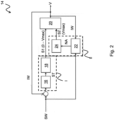
- the Figure 2 shows the braking device 14 in detail.
- the braking device 14 comprises a controller 16, an adjusting element 18, a brake unit 20, a comparison unit 22 and an emergency trigger 24.
- the braking device 14 is electrically ventilated according to the present embodiment.
- the braking device can also be ventilated hydraulically or pneumatically.
- the braking device 14 is supplied with a setpoint SW for the deceleration depending on the degree of loading of the car 4.
- the setpoint SW is compared with a measured actual value IW of the delay, and the difference, ie the control deviation, is fed to the controller 16, which determines a manipulated variable ST based on this difference between the setpoint SW and the actual value IW.
- the manipulated variable ST is supplied to the adjusting element 18, which transmits a first control signal S1 to the brake unit 20 for providing a variable braking force V between a minimum braking force and a maximum braking force Vmax.
- the value of the minimum braking force can also be zero.
- a first triggering path I of the braking device 14 is active, wherein according to the present embodiment, the first triggering path I includes the controller 16 and the adjusting element 18. The control deviation is thus supplied as an input to the first triggering path I and the first control signal S1 controls the brake unit 20 as an output.
- a second trigger path II is provided.
- the comparison unit 22 compares the difference between the setpoint SW and the actual value IW with a predetermined limit value.
- the comparison unit 22 can have a comparator. If the difference exceeds the specified limit value, it is concluded that the car 4 is not being overspeeded.
- An emergency trigger signal NA is then generated by the comparison unit 22 and transmitted to the emergency trigger 24.
- the emergency trigger generates a second control signal S2 that is transmitted to the brake unit 20 to provide the maximum braking force Vmax. Therefore, in the event of a fault, a second trigger path II is active, with the second trigger path II having the comparison unit 22 and the emergency trigger 24 according to the present embodiment.
- the difference between the setpoint SW and the actual value IW is thus supplied as an input to the second trigger path II and the second control signal S2 controls the brake unit 20 as an output.
- the braking device 14 In order to ensure reliable operation of the braking device 14, for example in the event of an interruption in the energy supply to the elevator 2, the braking device 14 has a buffer battery (not shown) which supplies components of the braking device 14, such as the comparison unit 22, with electrical energy.
- the brake unit 20 can be controlled in normal operation via the first trigger path I and in the event of a fault via the second trigger path II in order to provide a braking force.
- the variable braking force V according to the present embodiment a regulated braking force, is provided via the first triggering path I, while the maximum braking force Vmax is provided via the second triggering path II.
- the first trigger path I is therefore not safety-relevant, while the second trigger path II is safety-relevant. This means that only the components of the second trigger path II need to be designed and tested in a safety-relevant manner.
- control of the variable braking force V can also be provided.
- the Figure 3 shows the structure of the adjusting element 18 and the brake unit 20 of the braking device 14 in detail.
- the adjusting element 18 has an actuator 26 and a gear 28 connected to the actuator 26 on the input side.
- the actuator 26 can be an electric motor.
- the actuator can also be a hydraulic or pneumatic cylinder.
- the gear 28 can be a self-locking gear, such as a spindle gear.
- a displacement-force converter 30 of the brake unit 20 is connected to the transmission 28 on the output side.
- the brake unit 20 also has a clutch 32, a first energy storage 34 and a brake 36.
- the path-force converter 30 may have an elastic element, such as a spring, that converts a change in path into a change in force.
- the change in path is provided by the adjusting element 18 with the actuator 26 and the gear 28.
- a self-locking design of the gear 28 means that the elastic element does not relax when the adjusting element 18 is deactivated, for example due to an interruption in the energy supply to the elevator 2, but rather the elastic element retains its shape.
- the clutch 32 decouples the adjusting element 18 from the displacement-force converter 30 and, as will be described, releases braking energy.
- the first energy storage 34 provides the maximum braking force Vmax.
- the brake 36 provides the variable braking force V or the maximum braking force Vmax, depending on whether it is triggered via the first triggering path I or the second triggering path II.
- the Figure 4 shows further details of the displacement-force converter 30, the first energy storage 34 and the brake 36 of the braking device 2.
- a second energy storage 48 is assigned to the displacement-force converter 30.
- the second energy storage is a counterspring.
- the first energy storage device 34 has a compression spring 46.
- the brake 36 has two brake pads 38a, 38b, which engage on both sides of the guide rail 6a and 6b.
- the Figure 5 shows schematically a section through a first embodiment of the braking device 14 with the brake 36 in the open state.
- the first energy storage 34 is connected at its first end to the brake pad 38a in a force-transmitting manner, while the second end of the braking energy storage 34 is connected to the brake housing 44 in a force-transmitting manner. Therefore, the braking device 14 is mounted floating on the car 4. A second end of the adjusting element 18 is connected to a first end of the displacement-force converter 30 in a force-transmitting manner.
- a second end of the displacement-force converter 30 is connected to a first end of the coupling 32 in a force-transmitting manner.
- the second end of the clutch 32 is in engagement with a release shaft 42 of the braking device 14, which in turn is connected at its front end to the brake pad 38a.
- a stop device 40 is arranged parallel to the displacement-force converter 30, which limits a movement of the clutch 32 with respect to the adjusting element 18, caused by tensioning or relaxing the displacement-force converter 30.
- the first energy storage 34 provides the maximum braking force Vmax, while the second energy storage 48 provides the adjustable counterforce Vg, which reduces the maximum braking force Vmax.
- the adjustable counterforce Vg can assume values from the minimum braking force to the maximum braking force Vmax, whereby the minimum braking force can also be zero. The maximum braking force Vmax and the adjustable counterforce Vg are thus subtractively superimposed.
- the Figure 6 shows that to adjust the variable braking force V, for example according to the comparison of the setpoint SW and the actual value IW, the adjusting element 18 can be moved by the actuator 26 and the gear 28 along the direction of extension of the trigger shaft 42 after the brake pads 38a, 38b in System with the guide rail 6a, 6b were brought.
- the first trigger path I is active here.
- the adjusting element 18 Due to the active clutch 32, which is in engagement with the release shaft 42, the adjusting element 18 is moved in the direction of arrow A, which causes the counterspring to relax by discharging the second energy storage 48. This change in path results in the counterspring of the second energy storage 48 providing a reduced, adjustable counterforce Vg, so that the effective variable braking force V increases. If, on the other hand, the adjusting element 18 is moved counter to the direction of arrow A, this causes the counterspring to be tensioned by charging the second energy storage device 48. This change in path results in the counterspring of the second energy storage device 48 providing an increased adjustable counterforce Vg, so that the acting variable Braking force V reduced.
- the Figure 7 shows that the movement of the adjusting element 18 in the direction of arrow A is limited by the stop device 40. In this situation, the counterspring of the second energy storage 48 does not provide an adjustable counterforce Vg, so that the braking device 14 provides the maximum braking force Vmax.
- the Figure 8 shows the braking device 14 in the event of a fault following a failure of the energy supply and an associated failure of, for example, the controller 16 or the adjusting element 18 and the occurrence of overspeed.
- the second trigger path II is active.
- the clutch 32 is then deactivated by the trigger element 24, so that the clutch 32 is no longer in engagement with the trigger shaft 42.
- the counterspring of the second energy storage device 48 is thus decoupled from the adjusting element 18 by activation. There is therefore no adjustable counterforce Vg that reduces the maximum braking force Vmax of the braking energy storage 34, so that the braking device 14 provides the maximum braking force Vmax.
- the adjusting element 18 is activated. As a result, the counter spring of the second energy storage 48 is relaxed again. In addition, the stop device 40 is taken along until the clutch 32 is again on the in Figure 5 Position shown on the release shaft 42 engages. The adjusting element 18 is further activated, so that the adjusting element 18 works against the compression spring 46 of the brake energy storage 34 in order to release the brake pads 38a, 38b from the guide rail 6a and 6b. Then the braking device 14 can be operated again in normal operation.
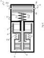
- the Figure 9 shows schematically a section through the braking device 14 in the open state according to a further embodiment.
- the braking device 14 and its components namely the adjusting element 18, the first energy storage 34 in the form of a compression spring 46, the displacement-force converter 30, the second energy storage 48 in the form of a counterspring, the clutch 32 and the stop device 40 as well as the brake pads 38a , 38b are accommodated in a housing 44.
- the actuator 26 is designed as a hollow shaft drive and is in engagement with the release shaft 42.
- the clutch 32 can effect a force transmission through a frictional connection, which allows the brake 36 to be activated particularly quickly.
Landscapes
- Engineering & Computer Science (AREA)
- Mechanical Engineering (AREA)
- Maintenance And Inspection Apparatuses For Elevators (AREA)
- Braking Arrangements (AREA)
Description
Die vorliegende Erfindung betrifft einen Aufzug mit einer Bremsvorrichtung, insbesondere einer Betriebsbremse oder einer Fangvorrichtung.The present invention relates to an elevator with a braking device, in particular a service brake or a safety gear.
Bei Aufzügen sind Betriebsbremsen und Fangvorrichtungen zwingend erforderlich, die bei Übergeschwindigkeit bzw. unkontrollierten Fahrbewegungen den Fahrkorb des Aufzugs sicher bis zum Stillstand verzögern.For elevators, service brakes and safety gear are absolutely necessary, which safely decelerate the elevator car to a standstill in the event of excessive speed or uncontrolled movement.
Derartige Betriebsbremsen können z.B. an einer Treibscheibe des Aufzugs angreifen oder an dem Fahrkorb des Aufzugs angeordnet sein und an den Führungsschienen angreifen.Such service brakes can, for example, act on a traction sheave of the elevator or be arranged on the car of the elevator and act on the guide rails.
Eine Bremsvorrichtung erzeugt bevorzugt eine konstante Bremskraft, die üblicherweise so eingestellt wird, dass der mit einer Nennlast beladene Fahrkorb mit einer Verzögerung von 0,8 bis 1 g für Fangvorrichtungen und 0,3 bis 0,5 g für Betriebsbremsen abgebremst wird.A braking device preferably generates a constant braking force, which is usually set so that the car loaded with a nominal load is braked with a deceleration of 0.8 to 1 g for safety gears and 0.3 to 0.5 g for service brakes.
Um die Verletzungsgefahr von Aufzugpassagieren während eines Bremsvorgangs des Fahrkorbs zu minimieren kann die Bremsverzögerung der Bremsvorrichtung durch Einstellen, z.B. durch Steuerung oder Regelung, begrenzt werden. Da die Bremsverzögerung des Fahrkorbs von Fahrkorbgewicht und der Zuladung des Fahrkorbs abhängt, sollte die Bremskraft an die Zuladung des Fahrkorbs angepasst werden. Eine derartige Bremsvorrichtung muss bei steigender Komplexität immer noch das erforderliche Maß an Sicherheit gewährleisten. Eine Sicherheitsanforderung ist, dass die Bremsvorrichtung nach dem Ruhestromprinzip arbeitet (aktiv, wenn eingeschaltet). Jedoch erfordert das Ruhestromprinzip eine ständige Energieeinspeisung in eine Aktorik der Bremsvorrichtung. Dies führt zu einem erhöhten Energieverbrauch der Bremsvorrichtung.In order to minimize the risk of injury to elevator passengers during a braking process of the car, the braking deceleration of the braking device can be limited by adjustment, for example by control or regulation. Since the braking deceleration of the car depends on the weight of the car and the load of the car, the braking force should be adjusted to the load of the car. Such a braking device must still ensure the required level of safety despite increasing complexity. A safety requirement is that the braking device works according to the closed-circuit principle (active when switched on). However, the quiescent current principle requires constant Energy feed into an actuator of the braking device. This leads to increased energy consumption by the braking device.
Wenn hingegen die Bremsvorrichtung nach dem Arbeitsstromprinzip arbeitet, ist ein Energiespeicher erforderlich, der die zum Schließen der Bremsvorrichtung erforderliche Energie bereitstellt, wenn eine Energieversorgung der Bremsvorrichtung unterbrochen ist. Da eine Regelung der Bremskraft mit einem hohen Energiebedarf einhergeht, müssen große Energiemengen bereitgestellt werden. Dies führt zu einer Bremsvorrichtung mit einem komplexen Aufbau.However, if the braking device works according to the working current principle, an energy storage device is required which provides the energy required to close the braking device when an energy supply to the braking device is interrupted. Since regulating the braking force involves a high energy requirement, large amounts of energy must be provided. This results in a braking device with a complex structure.
Einen weiteren entscheidenden Einfluss auf die Bremskraft hat der Bremsbelag, insbesondere der Reibungskoeffizient zwischen dem Bremsbelag und der Führungsschiene oder der Treibscheibe. Eine Veränderung des Reibungskoeffizienten wirkt sich direkt auf die Bremskraft und auf die sich einstellende Verzögerung aus. Wenn eine Bremskraftkorrektur auf einen Veränderung des Reibungskoeffizienten hin nicht vorgesehen ist, hat dies zur Folge, dass die Bremskraft entweder zunimmt und der Fahrkorb stärker verzögert wird, oder aber die Bremskraft abnimmt, wenn sich beispielsweise Öl auf der Führungsschiene befindet und der Fahrkorb dann nicht zum Stillstand kommt.The brake pad has another decisive influence on the braking force, in particular the coefficient of friction between the brake pad and the guide rail or the traction sheave. A change in the coefficient of friction has a direct effect on the braking force and the resulting deceleration. If a braking force correction due to a change in the coefficient of friction is not provided, the result is that the braking force either increases and the car is decelerated more, or the braking force decreases if, for example, there is oil on the guide rail and the car then does not move Standstill comes.
Ferner sind Bremseinrichtungen, insbesondere Bremsbeläge, die bei einer Betriebsbremse häufig zum Einsatz kommen, verschleißbehaftet.Furthermore, braking devices, in particular brake pads, which are often used in a service brake, are subject to wear.
Eine Bremseinrichtung auf dem Fahrkorb kann zwei Bremseinheiten aufweisen, die jeweils an einer von zwei Führungsschienen angreifen. Die beiden Bremseinheiten der Bremseinrichtung sind starr (zwangläufig) über eine Welle miteinander verbunden. Dies hat zur Folge, dass auf Führungsschienen, die auf beiden Seiten des Fahrkorbs angeordnet sind, zunächst die gleichen Bremskräfte wirken. Durch Toleranzen, Führungsschienenbeschaffenheit oder unterschiedliche Verschmutzung können jedoch aufgrund der oben genannten Verschleißprozesse an beiden Seiten des Fahrkorbs unterschiedliche Bremskräfte wirken und den Fahrkorb durch ein sich hierdurch einstellendes Drehmoment zusätzlich belasten.A braking device on the car can have two braking units, each of which acts on one of two guide rails. The two braking units of the braking device are rigidly (forcibly) connected to one another via a shaft. This means that the same braking forces initially act on guide rails that are arranged on both sides of the car. Due to tolerances, the nature of the guide rails or different levels of contamination, however, due to the wear processes mentioned above, different braking forces can act on both sides of the car and put additional strain on the car due to the resulting torque.
Die
Aus der
Es besteht Bedarf an einem Aufzug mit einer Bremsvorrichtung, wobei die Bremsvorrichtung eine Bremskraft einstellbarer und damit an die jeweilige Betriebssituation angepasster Größe bereitstellt und die einen einfachen Aufbau aufweist.There is a need for an elevator with a braking device, wherein the braking device provides a braking force that is adjustable and therefore adapted to the respective operating situation and which has a simple structure.
Die vorliegende Erfindung betrifft einen Aufzug nach Anspruch 1. Vorteilhafte Ausgestaltungen sind Gegenstand der Unteransprüche sowie der nachfolgenden Beschreibung.The present invention relates to an elevator according to claim 1. Advantageous refinements are the subject of the subclaims and the following description.
Der erfindungsgemäße Aufzug weist eine Bremsvorrichtung, insbesondere eine Betriebsbremse und/oder Fangvorrichtung, auf, wobei die Bremsvorrichtung zum Bereitstellen einer variablen Bremskraft von einer minimalen Bremskraft bis zu einer maximalen Bremskraft ausgebildet ist. Zum Bereitstellen der variablen Bremskraft sind ein erster Energiespeicher zum Bereitstellen der maximalen Bremskraft und ein zweiter Energiespeicher zum Bereitstellen einer der maximalen Bremskraft entgegengesetzt gerichteten, einstellbaren Gegenkraft vorgesehen. Dabei ist die variable Bremskraft die Differenz aus der maximalen Bremskraft und der einstellbaren Gegenkraft.The elevator according to the invention has a braking device, in particular a service brake and/or safety gear, wherein the braking device is designed to provide a variable braking force from a minimum braking force to a maximum braking force. To provide the variable braking force, a first energy storage device is used to provide the maximum Braking force and a second energy storage for providing an adjustable counterforce directed opposite to the maximum braking force are provided. The variable braking force is the difference between the maximum braking force and the adjustable counterforce.
Die Erfindung beruht auf der Erkenntnis, dass durch subtraktives Überlagern der maximalen Bremskraft und der bereitgestellten einstellbaren Gegenkraft auf besonders einfache weise eine Bremskraft einstellbarer Größe und damit variable Bremskraft bereitgestellt werden kann. Somit wird eine Bremsvorrichtung mit einfachem Aufbau bereitgestellt, mit der eine variable Bremskraft im Normalbetrieb und im Notfall eine maximale Bremskraft bereitgestellt werden kann.The invention is based on the knowledge that by subtractively superimposing the maximum braking force and the adjustable counterforce provided, a braking force of adjustable magnitude and thus variable braking force can be provided in a particularly simple manner. A braking device with a simple structure is thus provided, with which a variable braking force can be provided during normal operation and a maximum braking force in an emergency.
In einer vorteilhaften Ausgestaltung der Erfindung weist der erste Energiespeicher eine Druckfeder zum Bereitstellen der maximalen Bremskraft auf. Hierdurch wird eine Bremsvorrichtung mit einem besonders einfachen Aufbau bereitgestellt.In an advantageous embodiment of the invention, the first energy storage device has a compression spring for providing the maximum braking force. This provides a braking device with a particularly simple structure.
In einer vorteilhaften Ausgestaltung der Erfindung weist der zweite Energiespeicher eine Gegenfeder zum Bereitstellen der einstellbaren Gegenkraft auf. Auch hierdurch wird eine Bremsvorrichtung mit einem besonders einfachen Aufbau bereitgestellt.In an advantageous embodiment of the invention, the second energy storage device has a counterspring for providing the adjustable counterforce. This also provides a braking device with a particularly simple structure.
In einer vorteilhaften Ausgestaltung der Erfindung ist ein Verstellelement mit dem zweiten Energiespeicher zusammenwirkend zum Einstellen der einstellbaren Gegenkraft vorgesehen. Somit kann die Größe der einstellbaren Gegenkraft im Normalbetrieb mit dem Verstellelement eingestellt werden, während im Notfall das Verstellelement inaktiv ist und die maximale Bremskraft bereitgestellt wird.In an advantageous embodiment of the invention, an adjusting element is provided to cooperate with the second energy storage device in order to adjust the adjustable counterforce. Thus, the size of the adjustable counterforce can be adjusted in normal operation with the adjusting element, while in an emergency the adjusting element is inactive and the maximum braking force is provided.
In einer vorteilhaften Ausgestaltung der Erfindung weist das Verstellelement einen Aktuator zum Aufladen und Entladen des zweiten Energiespeichers auf. Somit kann durch Ansteuern des Aktuators der zweite Energiespeicher, z.B. die Gegenfeder, durch Spannen mit Bremsenergie aufgeladen und durch Entspannen entladen werden. So kann die Höhe der einstellbaren Gegenkraft eingestellt werden. Auch hierdurch wird eine Bremsvorrichtung mit einem besonders einfachen Aufbau bereitgestellt.In an advantageous embodiment of the invention, the adjusting element has an actuator for charging and discharging the second energy storage. Thus, by activating the actuator, the second energy storage, e.g. the counterspring, can be charged with braking energy by tensioning and discharged by relaxing. This allows the height of the adjustable counterforce to be adjusted. This also provides a braking device with a particularly simple structure.
In einer vorteilhaften Ausgestaltung der Erfindung ist der Aktuator des Verstellelements als Hohlwellenantrieb ausgebildet. Hierdurch wird eine Bremsvorrichtung mit besonders kompakten Abmessungen bereitgestellt, die besonders wenig Bauraum in Anspruch nimmt.In an advantageous embodiment of the invention, the actuator of the adjusting element is designed as a hollow shaft drive. This provides a braking device with particularly compact dimensions that takes up particularly little space.
In einer vorteilhaften Ausgestaltung der Erfindung sind ein erster Auslösepfad und ein zweiter Auslösepfad zum Auslösen der Bremsvorrichtung vorgesehen. Bei aktiven ersten Auslösepfad stellt die Bremsvorrichtung die variable Bremskraft bereit, und bei aktiven zweiten Auslösepfad stellt die Bremsvorrichtung die maximale Bremskraft bereit. Dabei wird unter einem Auslösepfad ein Signallaufweg eines Steuersignals zum Ansteuern der Bremsvorrichtung verstanden, das mehrere Komponenten der Bremsvorrichtung durchläuft. Der erste und der zweite Auslösepfad verlaufen dabei zumindest abschnittsweise parallel zueinander und bilden somit zwei Alternativen zum Auslösen der Bremsvorrichtung. Durch das Bereitstellen des zweiten Auslösepfads, der im Unterschied zum ersten Auslösepfad sicherheitsrelevant ist, muss lediglich die zum Betrieb des zweiten Auslösepfads erforderliche Energie bereitgestellt werden für den Fall, dass die Energieversorgung unterbrochen ist. Dabei ist der Energiebedarf für den deutlich einfacher aufgebauten zweiten Auslösepfad geringer, was einen einfacheren Aufbau erlaubt. Somit führt der durch den zweiten Auslösepfad reduzierte Energiebedarf zu einem einfacheren Aufbau der Bremsvorrichtung, die eine einstellbare Bremskraft breitstellt.In an advantageous embodiment of the invention, a first trigger path and a second trigger path are provided for triggering the braking device. When the first trigger path is active, the braking device provides the variable braking force, and when the second trigger path is active, the braking device provides the maximum braking force. A trigger path is understood to mean a signal path of a control signal for activating the braking device, which passes through several components of the braking device. The first and second trigger paths run parallel to one another at least in sections and thus form two alternatives for triggering the braking device. By providing the second triggering path, which is safety-relevant in contrast to the first triggering path, only the energy required to operate the second triggering path needs to be provided in the event that the energy supply is interrupted. The energy requirement for the second trigger path, which has a much simpler structure, is lower, which allows for a simpler structure. The energy requirement reduced by the second trigger path thus leads to a simpler structure of the braking device, which provides an adjustable braking force.
In einer vorteilhaften Ausgestaltung der Erfindung ist ein Auslöseelement zum Freischalten des zweiten Energiespeichers bei aktivem, zweitem Auslösepfad vorgesehen, wobei nach Freischaltung des zweiten Energiespeichers der zweite Energiespeicher von dem ersten Energiespeicher abgekoppelt ist. Nach Freischaltung des zweiten Energiespeichers ist somit die einstellbare Gegenkraft von dem Energiespeicher abgekoppelt. Mit dem Auslöseelement kann ein Wechsel von dem ersten Auslösepfad zu dem zweiten Auslösepfad bewirkt werden, bei dem der zweite Energiespeicher freigeschaltet wird, sodass keine einstellbare Gegenkraft mehr wirkt, die die vom dem Bremsenergiespeicher bereitgestellte maximale Bremskraft reduziert. Somit weist die Bremsvorrichtung einen besonders einfachen Aufbau auf.In an advantageous embodiment of the invention, a trigger element is provided for unlocking the second energy storage when the second trigger path is active, with the second energy storage being decoupled from the first energy storage after the second energy storage has been activated. After the second energy storage device has been activated, the adjustable counterforce is decoupled from the energy storage device. With the triggering element, a change from the first triggering path to the second triggering path can be effected, in which the second energy storage is activated, so that no adjustable counterforce that reduces the maximum braking force provided by the braking energy storage no longer acts. The braking device therefore has a particularly simple structure.
In einer vorteilhaften Ausgestaltung der Erfindung ist als Auslöseelement eine Kupplung vorgesehen. Die Kupplung kann eine kräfteübertragende Verbindung über Form- oder Reibschluss bereitstellen. Mit der Kupplung ist auf besonders einfache Weise ein Wechsel von dem ersten Auslösepfad zu dem zweiten Auslösepfad und zugleich ein Freischaltern des Weg-Kraft-Wandlers möglich. Somit erfüllt die Kupplung eine Doppelfunktion. Dies vereinfacht den Aufbau der Bremsvorrichtung. Ferner kann die Kupplung so ausgebildet sein, dass nur zum Öffnen der Kupplung Energie erforderlich ist. Dies reduziert den Energiebedarf nochmals.In an advantageous embodiment of the invention, a clutch is provided as a trigger element. The coupling can provide a force-transmitting connection via positive or frictional connection. The clutch makes it possible to change from the first triggering path to the second triggering path in a particularly simple manner and at the same time enable the displacement-force converter to be activated. The clutch therefore fulfills a dual function. This simplifies the structure of the braking device. Furthermore, the clutch can be designed such that energy is only required to open the clutch. This reduces the energy requirement again.
In einer vorteilhaften Ausgestaltung der Erfindung ist dem ersten Auslösepfad ein Regler zum Einstellen der variablen Bremskraft zugeordnet. Somit kann eine dem Beladungszustand und/oder Verschleißzustand der Bremsvorrichtung des Fahrkorbs entsprechende Bremskraft bereitgestellt werden. So kann z.B. sichergestellt werden, dass die Verzögerung auch bei einem nur geringfügig beladenen Fahrkorb einen definierten Wert, beispielsweise 0,8 bis 1 g, nicht überschreitet. Somit ist Verletzungsgefahr von Aufzugpassagieren während eines Bremsvorgangs des Fahrkorbs minimiert. Außerdem kann der Verschleißzustand beim Betrieb berücksichtig werden. Ferner kann bei einer beidseitig am Fahrkorb wirkenden Bremsvorrichtung die mechanische Belastung des Fahrkorbs durch ein Drehmoment reduziert werden.In an advantageous embodiment of the invention, a controller for adjusting the variable braking force is assigned to the first trigger path. A braking force corresponding to the loading condition and/or wear condition of the braking device of the car can thus be provided. For example, it can be ensured that the deceleration does not exceed a defined value, for example 0.8 to 1 g, even with a car that is only slightly loaded. This minimizes the risk of injury to elevator passengers during a braking process of the car. In addition, the state of wear can be taken into account during operation become. Furthermore, with a braking device acting on both sides of the car, the mechanical load on the car can be reduced by a torque.
In einer vorteilhaften Ausgestaltung der Erfindung ist der erste Auslösepfad nach dem Arbeitsstromprinzip arbeitend ausgebildet. Unter dem Arbeitsstromprinzip wird dabei verstanden, dass die Bremsvorrichtung geöffnet bzw. belüftet ist, wenn ein Bremsensteuersignal, wie ein elektrischer Strom oder eine elektrische Spannung, ungleich Null anliegt. Somit kann der erste Auslösepfad, der die Bremskraft gewünschter Größe bereitstellt, besonders energieeffizient ausgebildet sein. Daher kann die Bremsvorrichtung eine durch Steuerung oder Regelung einstellbare variable Bremskraft bei einem energieeffizienten Betrieb bereitstellen.In an advantageous embodiment of the invention, the first trigger path is designed to work according to the working current principle. The working current principle is understood to mean that the braking device is opened or ventilated when a brake control signal, such as an electrical current or an electrical voltage, is present that is not equal to zero. The first trigger path, which provides the braking force of the desired magnitude, can therefore be designed to be particularly energy-efficient. Therefore, the braking device can provide a variable braking force that can be adjusted by control or regulation with energy-efficient operation.
In einer vorteilhaften Ausgestaltung der Erfindung ist der zweite Auslösepfad nach dem Ruhestromprinzip arbeitend ausgebildet. Dabei wird unter dem Ruhestromprinzip verstanden, dass die Bremsvorrichtung geöffnet bzw. belüftet ist, wenn ein Bremsensteuersignal, wie ein elektrischer Strom oder eine elektrische Spannung, gleich Null anliegt. Somit kann der zweite Auslösepfad, der die maximale Bremskraft bereitstellt, sicherheitsrelevante Anforderungen bei einem energieeffizienten Betrieb erfüllen.In an advantageous embodiment of the invention, the second trigger path is designed to work according to the closed-circuit principle. The quiescent current principle means that the braking device is opened or ventilated when a brake control signal, such as an electrical current or an electrical voltage, is equal to zero. The second trigger path, which provides the maximum braking force, can therefore meet safety-relevant requirements during energy-efficient operation.
In einer vorteilhaften Ausgestaltung der Erfindung weist die Bremsvorrichtung ein selbsthemmendes Getriebe zum Einstellen der variablen Bremskraft auf, das dem ersten Auslösepfad zugeordnet ist. Bei dem selbsthemmenden Getriebe kann es sich z.B. um ein Spindelgetriebe handeln. Somit ist nur zusätzliche Energie notwendig, um die variable Bremskraft einzustellen, jedoch nicht, um einen eingestellten Bremskraftwert festzuhalten. Somit wird der Energiebedarf der Bremsvorrichtung nochmals reduziert.In an advantageous embodiment of the invention, the braking device has a self-locking gear for adjusting the variable braking force, which is assigned to the first trigger path. The self-locking gear can be, for example, a spindle gear. Additional energy is therefore only necessary to set the variable braking force, but not to maintain a set braking force value. The energy requirement of the braking device is thus further reduced.
Weitere Vorteile und Ausgestaltungen der Erfindung ergeben sich aus der Beschreibung und der beiliegenden Zeichnung.Further advantages and refinements of the invention result from the description and the accompanying drawing.
Es versteht sich, dass die vorstehend genannten und die nachstehend noch zu erläuternden Merkmale nicht nur in der jeweils angegebenen Kombination, sondern auch in anderen Kombinationen oder in Alleinstellung im Schutzumfang der beigefügten Ansprüche verwendbar sind.It is understood that the features mentioned above and those to be explained below can be used not only in the combination specified in each case, but also in other combinations or alone within the scope of protection of the appended claims.
Die Erfindung ist anhand einer Ausführungsform in der Zeichnung schematisch dargestellt und wird im Folgenden unter Bezugnahme auf die Zeichnung ausführlich beschrieben.The invention is shown schematically in the drawing using an embodiment and is described in detail below with reference to the drawing.
-
Figur 1 zeigt schematisch eine bevorzugte Ausführungsform eines erfindungsgemäßen Aufzugs mit einer Bremsvorrichtung in schematischer Darstellung.Figure 1 shows schematically a preferred embodiment of an elevator according to the invention with a braking device in a schematic representation. -
Figur 2 zeigt schematisch eine bevorzugte Ausführungsform einer erfindungsgemäßen Bremsvorrichtung.Figure 2 shows schematically a preferred embodiment of a braking device according to the invention. -
Figur 3 zeigt schematisch weitere Details der Bremsvorrichtung gemäß Figur 2.Figure 3 shows schematically further details of the braking device according to Figure 2. -
Figur 4 zeigt schematisch weitere Details der Bremsvorrichtung gemäß Figur 3.Figure 4 shows schematically further details of the braking device according to Figure 3. -
Figur 5 zeigt schematisch einen Schnitt durch eine bevorzugte Ausführungsform der Bremsvorrichtung im offenen Zustand gemäß einer weiteren Ausführungsform.Figure 5 shows schematically a section through a preferred embodiment of the braking device in the open state according to a further embodiment. -
Figur 6 zeigt die Bremsvorrichtung gemäßFigur 5 in geschlossenem Zustand.Figure 6 shows the braking device according toFigure 5 in closed state. -
Figur 7 zeigt die Bremsvorrichtung gemäßFigur 5 in geschlossenem Zustand, eine maximale Bremskraft über einen ersten Auslösepfad bereitstellend.Figure 7 shows the braking device according toFigure 5 in the closed state, providing maximum braking force over a first trigger path. -
Figur 8 zeigt die Bremsvorrichtung gemäßFigur 5 in geschlossenem Zustand, eine maximale Bremskraft über einen zweiten Auslösepfad bereitstellend.Figure 8 shows the braking device according toFigure 5 when closed, providing maximum braking force via a second trigger path. -
Figur 9 zeigt schematisch einen Schnitt durch eine bevorzugte Ausführungsform der Bremsvorrichtung im offenen Zustand gemäß einer weiteren Ausführungsform.Figure 9 shows schematically a section through a preferred embodiment of the braking device in the open state according to a further embodiment.
In
Der Aufzug 2 weist einen Fahrkorb 4 zum Transport von Personen und/oder Lasten auf, der in oder entgegen der Schwerkraftrichtung g entlang zwei parallel zueinander verlaufenden Führungsschienen 6a, 6b in einem Aufzugschacht verfahrbar ist. Abweichend von der vorliegenden Ausführungsform kann jedoch der Fahrkorb 4 z.B. auch entlang einer einzigen Führungsschiene verfahrbar sein.The
Zum Verfahren des Fahrkorbs 4 ist ein Antrieb 50 vorgesehen, der in der vorliegenden Ausführungsform als Treibscheibenantrieb ausgebildet ist. Der Fahrkorb 4 kann dabei eine Kabine und einen Fangrahmen (beides nicht dargestellt) aufweisen. Der Antrieb 50 weist gemäß der vorliegenden Ausführungsform ein Tragmittel 8, wie z.B. Tragseile, auf, das an der Oberseite des Fahrkorbs 4 befestigt ist. Das Tragmittel 8 läuft auf einer Treibscheibe 12, die mittels eines Motors (nicht dargestellt) motorisch antreibbar ist, um den Fahrkorb 4 zu verfahren. An dem anderen, dem Fahrkorb 4 gegenüberliegenden Ende, ist gemäß der vorliegenden Ausführungsform ein Gegengewicht 10 befestigt, dass durch Gewichtsausgleich den Kraftaufwand zum Verfahren des Fahrkorbs 4 reduziert. Abweichend von der vorliegenden Ausführungsform kann jedoch auch ein anderer Antrieb Verwendung finden, wie z.B. ein Linearantrieb.To move the car 4, a
Um den Fahrkorb 4 bis zum Stillstand abzubremsen, z.B. wenn Übergeschwindigkeiten und/oder unkontrollierte Fahrbewegungen des Fahrkorbs 4 auftreten, ist eine Bremsvorrichtung 14 vorgesehen, die im vorliegenden Ausführungsform als Betriebsbremse und/oder Fangvorrichtung ausgebildet ist und beidseitig an dem Fahrkorb 4 angeordnet ist, sodass die Bremsvorrichtung 14 an beiden Führungsschienen 6a bzw. 6b angreift.In order to brake the car 4 to a standstill, e.g. if overspeeds and/or uncontrolled travel movements of the car 4 occur, a
Die
Gemäß der vorliegenden Ausführungsform umfasst die Bremsvorrichtung 14 einen Regler 16, ein Verstellelement 18, eine Bremseneinheit 20, eine Vergleichseinheit 22 und einen Notfallauslöser 24.According to the present embodiment, the
Die Bremsvorrichtung 14 wird gemäß der vorliegenden Ausführungsform elektrisch belüftet. Alternativ kann die Bremsvorrichtung auch hydraulisch oder pneumatisch belüftet werden.The
Im Normalbetrieb wird der Bremsvorrichtung 14 ein Sollwert SW für die Verzögerung in Abhängigkeit von dem Beladungsgrad des Fahrkorbs 4 zugeführt. Der Sollwert SW wird mit einem gemessenen Istwert IW der Verzögerung verglichen, und die Differenz, d.h. die Regelabweichung, wird dem Regler 16 zugeführt, der basierend auf dieser Differenz zwischen Sollwert SW und Istwert IW eine Stellgröße ST bestimmt.During normal operation, the
Die Stellgröße ST wird dem Verstellelement 18 zugeführt, das ein erstes Steuersignal S1 zum Bereitstellen einer variablen Bremskraft V zwischen einer minimalen Bremskraft und einer maximalen Bremskraft Vmax an die Bremseneinheit 20 überträgt. Der Wert der minimalen Bremskraft kann auch Null sein. Somit ist im Normalbetrieb ein erster Auslösepfad I der Bremsvorrichtung 14 aktiv, wobei gemäß der vorliegenden Ausführungsform der erste Auslösepfad I den Regler 16 und das Verstellelement 18 umfasst. Somit wird als Eingang dem ersten Auslösepfad I die Regelabweichung zugeführt und als Ausgang steuert das erste Steuersignal S1 die Bremseneinheit 20 an.The manipulated variable ST is supplied to the adjusting
Um bei einem Ausfall der Energieversorgung des Aufzugs 2 und einem damit verbundenen Ausfall z.B. des Reglers 16 oder des Verstellelements 18 einen sicheren Betrieb des Aufzugs 2 zu gewährleisten, ist ein zweiter Auslösepfad II vorgesehen.In order to ensure safe operation of the
Zur Aktivierung des zweiten Auslösepfads II wird von der Vergleichseinheit 22 die Differenz aus dem Sollwert SW und dem Istwert IW mit einem vorgegebenen Grenzwert verglichen. Hierzu kann die Vergleichseinheit 22 einen Komparator aufweisen. Übersteigt die Differenz den vorgegebenen Grenzwert, wird auf eine unzulässige Übergeschwindigkeit des Fahrkorbs 4 geschlossen. Hierauf wird ein Notfall-Auslösesignal NA von der Vergleichseinheit 22 erzeugt und zum Notfallauslöser 24 übertragen. Der Notfallauslöser erzeugt ein zweites Steuersignal S2, dass an die Bremseneinheit 20 zum Bereitstellen der maximalen Bremskraft Vmax übertragen wird. Daher ist im Fehlerfall ein zweiter Auslösepfad II aktiv, wobei gemäß der vorliegenden Ausführungsform der zweite Auslösepfad II die Vergleichseinheit 22 und den Notfallauslöser 24 aufweist. Somit wird als Eingang dem zweiten Auslösepfad II die Differenz aus dem Sollwert SW und dem Istwert IW zugeführt und als Ausgang steuert das zweite Steuersignal S2 die Bremseneinheit 20 an.To activate the second trigger path II, the
Um einen zuverlässigen Betrieb der Bremsvorrichtung 14 zu gewährleiten, z.B. bei einer Unterbrechung der Energieversorgung des Aufzugs 2, weist die Bremsvorrichtung 14 eine Pufferbatterie (nicht dargestellt) auf, die Komponenten der Bremsvorrichtung 14, wie z.B. die Vergleichseinheit 22, mit elektrischer Energie versorgt.In order to ensure reliable operation of the
Somit kann die Bremseneinheit 20 im Normalbetrieb über den ersten Auslösepfad I und im Fehlerfall über den zweiten Auslösepfad II angesteuert werden, um eine Bremskraft bereitzustellen. Dabei wird über den ersten Auslösepfad I die variable Bremskraft V, gemäß der vorliegenden Ausführungsform eine geregelte Bremskraft, bereitgestellt, während über den zweiten Auslösepfad II die maximale Bremskraft Vmax bereitgestellt wird.Thus, the
Der erste Auslösepfad I ist somit nicht sicherheitsrelevant, während der zweite Auslösepfad II sicherheitsrelevant ist. Somit sind nur die Komponenten des zweiten Auslösepfads II sicherheitsrelevant auszulegen und zu prüfen.The first trigger path I is therefore not safety-relevant, while the second trigger path II is safety-relevant. This means that only the components of the second trigger path II need to be designed and tested in a safety-relevant manner.
Abweichend von der vorliegenden Ausführungsform kann anstelle einer Regelung der Bremskraft auch eine Steuerung der variablen Bremskraft V vorgesehen sein.Deviating from the present embodiment, instead of regulating the braking force, control of the variable braking force V can also be provided.
Die
Das Verstellelement 18 weist gemäß der vorliegenden Ausführungsform einen Aktuator 26 und ein mit dem Aktuator 26 eingangsseitig verbundenes Getriebe 28 auf. Der Aktuator 26 kann ein Elektromotor sein. Alternativ kann der Aktuator auch ein Hydraulik- oder Pneumatikzylinder sein. Das Getriebe 28 kann ein selbsthemmendes Getriebe, wie z.B. ein Spindelgetriebe, sein.According to the present embodiment, the adjusting
Mit dem Getriebe 28 ist ausgangsseitig ein Weg-Kraft-Wandler 30 der Bremseneinheit 20 verbunden. Die Bremseneinheit 20 weist ferner gemäß der vorliegenden Ausführungsform eine Kupplung 32, einen ersten Energiespeicher 34 und eine Bremse 36 auf.A displacement-
Der Weg-Kraft-Wandler 30 kann ein elastisches Element, wie z.B. eine Feder, aufweisen, dass eine Wegänderung in eine Kraftänderung umwandelt. Die Wegänderung wird dabei von dem Verstellelement 18 mit dem Aktuator 26 und dem Getriebe 28 bereitgestellt. Eine selbsthemmende Ausbildung des Getriebes 28 bewirkt dabei, dass ein Entspannen des elastischen Elements bei Deaktivierung des Verstellelements 18, z.B. aufgrund einer Unterbrechung der Energieversorgung des Aufzugs 2 nicht erfolgt, sondern das elastische Element seine Form beibehält.The path-
Die Kupplung 32 entkoppelt bei einem Wechsel von dem ersten Auslösepfad I zu dem zweiten Auslösepfad II das Verstellelement 18 von dem Weg-Kraft-Wandler 30 und setzt, wie noch beschrieben wird, Bremsenergie frei.When changing from the first triggering path I to the second triggering path II, the clutch 32 decouples the adjusting
Der erste Energiespeicher 34 stellt, wie ebenfalls noch beschrieben wird, die maximale Bremskraft Vmax bereit.The
Die Bremse 36 stellt, je nach dem, ob sie über den ersten Auslösepfad I oder den zweiten Auslösepfad II ausgelöst wird, die variable Bremskraft V oder die maximale Bremskraft Vmax bereit.The
Die
Gemäß der vorliegenden Ausführungsform ist dem Weg-Kraft-Wandler 30 ein zweiter Energiespeicher 48 zugeordnet. Der zweite Energiespeicher ist gemäß der vorliegenden Ausführungsform eine Gegenfeder. Der erste Energiespeicher 34 weist eine Druckfeder 46 auf. Ferner zeigt die
Die
Zu erkennen ist, dass das Verstellelement 18 mit dem in
Somit ist der erste Energiespeicher 34 mit seinem ersten Ende mit dem Bremsbelag 38a kräfteübertragend verbunden, während das zweite Ende des Bremsenergiespeichers 34 mit dem Bremsengehäuse 44 kräfteübertragend verbunden ist. Daher ist die Bremsvorrichtung 14 auf dem Fahrkorb 4 schwimmend gelagert. Ein zweites Ende des Verstellelements 18 ist mit einem ersten Ende des Weg-Kraft-Wandlers 30 kräfteübertragend verbunden.Thus, the
Ferner ist anhand der
Des Weiteren ist parallel zum Weg-Kraft-Wandler 30 eine Anschlageinrichtung 40 angeordnet, die eine Bewegung der Kupplung 32 in Bezug auf das Verstellelement 18, hervorgerufen durch ein Spannen oder Entspannen des Weg-Kraft-Wandlers 30, begrenzt.Furthermore, a
Der erste Energiespeicher 34 stellt die maximale Bremskraft Vmax bereit, während der zweite Energiespeicher 48 die einstellbare Gegenkraft Vg bereitstellt, die die maximale Bremskraft Vmax reduziert. Die einstellbare Gegenkraft Vg kann Werte von der minimalen Bremskraft bis zu der maximalen Bremskraft Vmax annehmen, wobei die minimale Bremskraft auch Null sein kann. Somit werden die maximale Bremskraft Vmax und die einstellbare Gegenkraft Vg subtraktiv überlagert.The
Die
Aufgrund der aktiven Kupplung 32, die in Eingriff mit der Auslösewelle 42 steht, wird das Verstellelement 18 in Pfeilrichtung A bewegt, was eine Entspannung der der Gegenfeder durch Entladung des zweiten Energiespeichers 48 bewirkt. Diese Wegänderung hat zur Folge, dass die Gegenfeder des zweiten Energiespeichers 48 eine reduzierte einstellbare Gegenkraft Vg bereitstellt, so dass sich die wirkende variable Bremskraft V erhöht. Wird hingegen das Verstellelement 18 entgegen der Pfeilrichtung A bewegt, bewirkt dies ein Spannen der Gegenfeder durch Laden des zweiten Energiespeichers 48. Diese Wegänderung hat zur Folge, dass die Gegenfeder des zweiten Energiespeichers 48 eine erhöhte einstellbare Gegenkraft Vg bereitstellt, so dass sich die wirkende variable Bremskraft V erniedrigt.Due to the active clutch 32, which is in engagement with the
Die
Die
Hieraufhin wird von dem Auslöseelement 24 die Kupplung 32 deaktiviert, so dass die Kupplung 32 nicht mehr in Eingriff mit der Auslösewelle 42 steht. Somit ist die Gegenfeder des zweiten Energiespeichers 48 von dem Verstellelement 18 durch Freischalten abgekoppelt. Es steht daher keine die maximale Bremskraft Vmax des Bremsenergiespeichers 34 reduzierende einstellbare Gegenkraft Vg bereit, sodass die Bremsvorrichtung 14 die maximale Bremskraft Vmax bereitstellt.The clutch 32 is then deactivated by the
Um nach Behebung des Fehlerfalls die Bremsvorrichtung 14 wieder in den Normalbetrieb zu überführen, wird das Verstellelement 18 aktiviert. Hierdurch wird die Gegenfeder des zweiten Energiespeichers 48 wieder entspannt. Außerdem wird die Anschlageinrichtung 40 mitgenommen, bis die Kupplung 32 wieder an der in
Die
Die Bremsvorrichtung 14 und ihre Komponenten, nämlich das Verstellelement 18, der erste Energiespeicher 34 in Form einer Druckfeder 46, der Weg-Kraft-Wandler 30, der zweite Energiespeicher 48 in Form einer Gegenfeder, die Kupplung 32 und die Anschlageinrichtung 40 sowie die Bremsbeläge 38a, 38b sind in einem Gehäuse 44 aufgenommen. Dabei ist der Aktuator 26 als Hohlwellenantrieb ausgebildet und steht in Eingriff mit der Auslösewelle 42. Die Kupplung 32 kann gemäß dieser Ausführungsform eine Kräfteübertragung durch einen Reibschluss bewirken, was eine besonders schnelle Aktivierung der Bremse 36 erlaubt.The
Claims (11)
- Elevator with a brake apparatus (14), in particular a service brake and/or safety catch, the brake apparatus (14) being configured to provide a variable brake force (V) from a minimum brake force up to a maximum brake force (Vmax), a first energy store (34) being provided to provide the maximum brake force (Vmax), a second energy store (48) being provided to provide an adjustable counterforce (Vg) which is directed counter to the maximum brake force (Vmax), the variable brake force (V) being the difference between the maximum brake force (Vmax) and the adjustable counterforce (Vg), a first triggering path (I) and a second triggering path (II) being provided to trigger the brake apparatus (14), the brake apparatus (14) being configured to provide the variable brake force (V) in the case of an active first triggering path (I), and the brake apparatus (14) being configured to provide the maximum brake force (Vmax) in the case of an active second triggering path (II), characterized in that a triggering element (24) is provided to enable the second energy store (48) in the case of an active second triggering path (II), the second energy store (48) being decoupled from the first energy store (34) after enabling of the second energy store (48) .
- Elevator according to Claim 1, the first energy store (34) having a compression spring (46) for providing the maximum brake force (Vmax).
- Elevator according to Claim 1 or 2, the second energy store (48) having a counter-spring for providing the counterforce (Vg).
- Elevator according to Claim 1, 2 or 3, an adjusting element (18) being provided so as to interact with the second energy store (48) in order to adjust the adjustable counterforce (Vg).
- Elevator according to Claim 4, the adjusting element (18) having an actuator (26) for loading and unloading the second energy store (48).
- Elevator according to Claim 5, the actuator (26) being configured as a hollow shaft drive.
- Elevator according to one of Claims 1 to 6, a coupling (32) being provided as triggering element (24).
- Elevator according to one of Claims 1 to 7, the first triggering path (I) being assigned a regulator (16) for adjusting the variable brake force (V).
- Elevator according to one of Claims 1 to 8, the first triggering path (I) being configured so as to operate in accordance with the load current principle.
- Elevator according to one of Claims 1 to 9, the second triggering path (II) being configured so as to operate in accordance with the closed current principle.
- Elevator according to one of Claims 1 to 10, the brake apparatus (14) having a self-locking gear mechanism (28) for adjusting the variable brake force (V), which gear mechanism (28) is assigned to the first triggering path (I).
Applications Claiming Priority (2)
| Application Number | Priority Date | Filing Date | Title |
|---|---|---|---|
| DE102014116281.1A DE102014116281A1 (en) | 2014-11-07 | 2014-11-07 | Elevator with a braking device |
| PCT/EP2015/074757 WO2016071141A1 (en) | 2014-11-07 | 2015-10-26 | Elevator with a brake device |
Publications (2)
| Publication Number | Publication Date |
|---|---|
| EP3215449A1 EP3215449A1 (en) | 2017-09-13 |
| EP3215449B1 true EP3215449B1 (en) | 2023-11-29 |
Family
ID=54364310
Family Applications (1)
| Application Number | Title | Priority Date | Filing Date |
|---|---|---|---|
| EP15787539.4A Active EP3215449B1 (en) | 2014-11-07 | 2015-10-26 | Elevator with a brake device |
Country Status (7)
| Country | Link |
|---|---|
| US (1) | US10351387B2 (en) |
| EP (1) | EP3215449B1 (en) |
| KR (1) | KR101941388B1 (en) |
| CN (1) | CN107074490B (en) |
| DE (1) | DE102014116281A1 (en) |
| FI (1) | FI3215449T3 (en) |
| WO (1) | WO2016071141A1 (en) |
Families Citing this family (5)
| Publication number | Priority date | Publication date | Assignee | Title |
|---|---|---|---|---|
| DE102015218025B4 (en) * | 2015-09-18 | 2019-12-12 | Thyssenkrupp Ag | elevator system |
| DE102016200593A1 (en) * | 2016-01-19 | 2017-07-20 | Thyssenkrupp Ag | Braking device for a car of an elevator system |
| DE102016217790A1 (en) | 2016-09-16 | 2018-03-22 | Thyssenkrupp Ag | Braking device for an elevator installation |
| ES2882640T3 (en) * | 2017-06-01 | 2021-12-02 | Kone Corp | Arrangement and procedure for changing the direction of movement of an elevator car, and the corresponding elevator |
| WO2022207232A1 (en) | 2021-03-31 | 2022-10-06 | Inventio Ag | Brake system for an elevator |
Citations (1)
| Publication number | Priority date | Publication date | Assignee | Title |
|---|---|---|---|---|
| US6719101B2 (en) * | 2000-12-08 | 2004-04-13 | Inventio Ag | Safety brake with retardation-dependent braking force |
Family Cites Families (11)
| Publication number | Priority date | Publication date | Assignee | Title |
|---|---|---|---|---|
| JPH04333487A (en) * | 1991-05-09 | 1992-11-20 | Hitachi Ltd | Elevator and brake device |
| FI105091B (en) | 1997-01-30 | 2000-06-15 | Kone Corp | Gejdbroms |
| US6193026B1 (en) * | 1997-12-22 | 2001-02-27 | Otis Elevator Company | Elevator brake |
| JP4709650B2 (en) * | 2003-10-07 | 2011-06-22 | オーチス エレベータ カンパニー | Remote resettable ropeless emergency stop for elevators |
| MY192706A (en) * | 2004-12-17 | 2022-09-02 | Inventio Ag | Lift installation with a braking device, and method for braking and holding a lift installation |
| ES2365255T3 (en) * | 2007-11-12 | 2011-09-27 | Thyssenkrupp Elevator Ag | BRAKING DEVICE FOR BRAKING A CABIN. |
| CN101463874A (en) * | 2007-12-19 | 2009-06-24 | 谢兴云 | Stacked braking thrust unit of normally closed brake |
| KR102068846B1 (en) * | 2011-09-30 | 2020-01-21 | 인벤티오 아게 | Brake device with electromechanical actuation |
| DE102014111359A1 (en) | 2014-05-20 | 2015-11-26 | Wittur Holding Gmbh | Method for operating a car brake unit |
| ES2902845T3 (en) | 2014-05-20 | 2022-03-30 | Wittur Holding Gmbh | Elevator Cabin Hydraulic Brake Unit with Controllable Braking Power |
| EP3197812B1 (en) * | 2014-09-24 | 2018-08-15 | Inventio AG | Elevator brake |
-
2014
- 2014-11-07 DE DE102014116281.1A patent/DE102014116281A1/en not_active Withdrawn
-
2015
- 2015-10-26 WO PCT/EP2015/074757 patent/WO2016071141A1/en active Application Filing
- 2015-10-26 US US15/522,352 patent/US10351387B2/en not_active Expired - Fee Related
- 2015-10-26 KR KR1020177015213A patent/KR101941388B1/en active IP Right Grant
- 2015-10-26 FI FIEP15787539.4T patent/FI3215449T3/en active
- 2015-10-26 EP EP15787539.4A patent/EP3215449B1/en active Active
- 2015-10-26 CN CN201580060545.4A patent/CN107074490B/en active Active
Patent Citations (1)
| Publication number | Priority date | Publication date | Assignee | Title |
|---|---|---|---|---|
| US6719101B2 (en) * | 2000-12-08 | 2004-04-13 | Inventio Ag | Safety brake with retardation-dependent braking force |
Also Published As
| Publication number | Publication date |
|---|---|
| WO2016071141A1 (en) | 2016-05-12 |
| US10351387B2 (en) | 2019-07-16 |
| US20170320706A1 (en) | 2017-11-09 |
| EP3215449A1 (en) | 2017-09-13 |
| KR20170084144A (en) | 2017-07-19 |
| CN107074490A (en) | 2017-08-18 |
| DE102014116281A1 (en) | 2016-05-12 |
| FI3215449T3 (en) | 2024-02-26 |
| KR101941388B1 (en) | 2019-01-22 |
| CN107074490B (en) | 2019-02-12 |
Similar Documents
| Publication | Publication Date | Title |
|---|---|---|
| EP3215449B1 (en) | Elevator with a brake device | |
| EP1979260B1 (en) | Control and regulation device for safeguarding a conveyor device, conveyor device and crane unit | |
| EP3126276B1 (en) | Elevator with a braking device | |
| EP3177555B1 (en) | Elevator system, braking system for an elevator system and method for controlling a braking system of an elevator system | |
| EP2058262B2 (en) | Braking device for braking a cabin | |
| EP1840068A1 (en) | Elevator system comprising an elevator car brake device and method for braking an elevator car | |
| EP3209589A1 (en) | Elevator comprising a decentralized electronic safety system | |
| EP1671912A1 (en) | Elevator system with braking unit and method to keep the elevator stopped | |
| EP2887535A1 (en) | Drive and control system for raising gates | |
| DE102013111385A1 (en) | Tripping device of a safety gear for an elevator car of an elevator installation | |
| DE102014017094A1 (en) | A servo control device having a function of reducing lowering in a braking operation | |
| EP3802244A1 (en) | Control device and method for controlling an actuator for actuating braking means of a vehicle, more particularly of a rail vehicle | |
| DE102012016336A1 (en) | Speed limiter for safety gear of elevator car for elevator system, has limiter wheel, in which rope of elevator system is performed, where locking unit is connected with limiter wheel | |
| EP0292685B1 (en) | Elevator drive with controller for jerkfree travel | |
| DE102018126964A1 (en) | BRAKE ARRANGEMENT FOR SECURING A CONVEYOR, CONVEYOR AND CRANE SYSTEM | |
| DE202012104436U1 (en) | Safety device for an elevator car of an elevator installation | |
| WO2020115304A1 (en) | Pressure medium-operated cabin brake and valve arrangement for controlling the emergency brake function of the pressure medium-operated cabin brake of a lift system | |
| WO2016005429A1 (en) | Elevator system comprising a braking mechanism on the elevator car, and method for operating same | |
| DE102012111071A1 (en) | Autonomous safety device for elevator car of elevator system, has brake element that is held at distance from running rail in driving position during normal running of elevator car by actuating element in driving position | |
| WO2018172120A1 (en) | Braking device for rail vehicles and method for braking rail vehicles | |
| DE202016101183U1 (en) | Elevator with a safety controller for directly influencing the braking force | |
| DE102011001449A1 (en) | Elevator system has safety catch device provided with brake device, triggering device and controller, where triggering device is connected with controller such that controller control and activates triggering device | |
| WO2017121760A1 (en) | Method for monitoring a first brake of a car of an elevator system | |
| DE19635244C2 (en) | Safety braking device for rope conveyors | |
| DE112021007075T5 (en) | Elevator device |
Legal Events
| Date | Code | Title | Description |
|---|---|---|---|
| STAA | Information on the status of an ep patent application or granted ep patent |
Free format text: STATUS: THE INTERNATIONAL PUBLICATION HAS BEEN MADE |
|
| PUAI | Public reference made under article 153(3) epc to a published international application that has entered the european phase |
Free format text: ORIGINAL CODE: 0009012 |
|
| STAA | Information on the status of an ep patent application or granted ep patent |
Free format text: STATUS: REQUEST FOR EXAMINATION WAS MADE |
|
| 17P | Request for examination filed |
Effective date: 20170503 |
|
| AK | Designated contracting states |
Kind code of ref document: A1 Designated state(s): AL AT BE BG CH CY CZ DE DK EE ES FI FR GB GR HR HU IE IS IT LI LT LU LV MC MK MT NL NO PL PT RO RS SE SI SK SM TR |
|
| AX | Request for extension of the european patent |
Extension state: BA ME |
|
| RAP1 | Party data changed (applicant data changed or rights of an application transferred) |
Owner name: THYSSENKRUPP ELEVATOR AG Owner name: THYSSENKRUPP AG |
|
| DAV | Request for validation of the european patent (deleted) | ||
| DAX | Request for extension of the european patent (deleted) | ||
| RAP1 | Party data changed (applicant data changed or rights of an application transferred) |
Owner name: THYSSENKRUPP AG Owner name: THYSSENKRUPP ELEVATOR AG |
|
| STAA | Information on the status of an ep patent application or granted ep patent |
Free format text: STATUS: EXAMINATION IS IN PROGRESS |
|
| 17Q | First examination report despatched |
Effective date: 20191010 |
|
| STAA | Information on the status of an ep patent application or granted ep patent |
Free format text: STATUS: EXAMINATION IS IN PROGRESS |
|
| TPAC | Observations filed by third parties |
Free format text: ORIGINAL CODE: EPIDOSNTIPA |
|
| TPAC | Observations filed by third parties |
Free format text: ORIGINAL CODE: EPIDOSNTIPA |
|
| RAP1 | Party data changed (applicant data changed or rights of an application transferred) |
Owner name: THYSSENKRUPP ELEVATOR INNOVATION AND OPERATIONS AG |
|
| STAA | Information on the status of an ep patent application or granted ep patent |
Free format text: STATUS: EXAMINATION IS IN PROGRESS |
|
| RAP3 | Party data changed (applicant data changed or rights of an application transferred) |
Owner name: TK ELEVATOR INNOVATION AND OPERATIONS GMBH |
|
| GRAP | Despatch of communication of intention to grant a patent |
Free format text: ORIGINAL CODE: EPIDOSNIGR1 |
|
| STAA | Information on the status of an ep patent application or granted ep patent |
Free format text: STATUS: GRANT OF PATENT IS INTENDED |
|
| INTG | Intention to grant announced |
Effective date: 20230719 |
|
| GRAS | Grant fee paid |
Free format text: ORIGINAL CODE: EPIDOSNIGR3 |
|
| GRAA | (expected) grant |
Free format text: ORIGINAL CODE: 0009210 |
|
| STAA | Information on the status of an ep patent application or granted ep patent |
Free format text: STATUS: THE PATENT HAS BEEN GRANTED |
|
| AK | Designated contracting states |
Kind code of ref document: B1 Designated state(s): AL AT BE BG CH CY CZ DE DK EE ES FI FR GB GR HR HU IE IS IT LI LT LU LV MC MK MT NL NO PL PT RO RS SE SI SK SM TR |
|
| REG | Reference to a national code |
Ref country code: GB Ref legal event code: FG4D Free format text: NOT ENGLISH |
|
| REG | Reference to a national code |
Ref country code: CH Ref legal event code: EP |
|
| REG | Reference to a national code |
Ref country code: DE Ref legal event code: R096 Ref document number: 502015016691 Country of ref document: DE |
|
| REG | Reference to a national code |
Ref country code: IE Ref legal event code: FG4D Free format text: LANGUAGE OF EP DOCUMENT: GERMAN |
|
| REG | Reference to a national code |
Ref country code: LT Ref legal event code: MG9D |
|
| REG | Reference to a national code |
Ref country code: NL Ref legal event code: MP Effective date: 20231129 |
|
| PG25 | Lapsed in a contracting state [announced via postgrant information from national office to epo] |
Ref country code: GR Free format text: LAPSE BECAUSE OF FAILURE TO SUBMIT A TRANSLATION OF THE DESCRIPTION OR TO PAY THE FEE WITHIN THE PRESCRIBED TIME-LIMIT Effective date: 20240301 |
|
| PG25 | Lapsed in a contracting state [announced via postgrant information from national office to epo] |
Ref country code: IS Free format text: LAPSE BECAUSE OF FAILURE TO SUBMIT A TRANSLATION OF THE DESCRIPTION OR TO PAY THE FEE WITHIN THE PRESCRIBED TIME-LIMIT Effective date: 20240329 |
|
| PG25 | Lapsed in a contracting state [announced via postgrant information from national office to epo] |
Ref country code: LT Free format text: LAPSE BECAUSE OF FAILURE TO SUBMIT A TRANSLATION OF THE DESCRIPTION OR TO PAY THE FEE WITHIN THE PRESCRIBED TIME-LIMIT Effective date: 20231129 |
|
| PG25 | Lapsed in a contracting state [announced via postgrant information from national office to epo] |
Ref country code: ES Free format text: LAPSE BECAUSE OF FAILURE TO SUBMIT A TRANSLATION OF THE DESCRIPTION OR TO PAY THE FEE WITHIN THE PRESCRIBED TIME-LIMIT Effective date: 20231129 |
|
| PG25 | Lapsed in a contracting state [announced via postgrant information from national office to epo] |
Ref country code: LT Free format text: LAPSE BECAUSE OF FAILURE TO SUBMIT A TRANSLATION OF THE DESCRIPTION OR TO PAY THE FEE WITHIN THE PRESCRIBED TIME-LIMIT Effective date: 20231129 Ref country code: IS Free format text: LAPSE BECAUSE OF FAILURE TO SUBMIT A TRANSLATION OF THE DESCRIPTION OR TO PAY THE FEE WITHIN THE PRESCRIBED TIME-LIMIT Effective date: 20240329 Ref country code: GR Free format text: LAPSE BECAUSE OF FAILURE TO SUBMIT A TRANSLATION OF THE DESCRIPTION OR TO PAY THE FEE WITHIN THE PRESCRIBED TIME-LIMIT Effective date: 20240301 Ref country code: ES Free format text: LAPSE BECAUSE OF FAILURE TO SUBMIT A TRANSLATION OF THE DESCRIPTION OR TO PAY THE FEE WITHIN THE PRESCRIBED TIME-LIMIT Effective date: 20231129 Ref country code: BG Free format text: LAPSE BECAUSE OF FAILURE TO SUBMIT A TRANSLATION OF THE DESCRIPTION OR TO PAY THE FEE WITHIN THE PRESCRIBED TIME-LIMIT Effective date: 20240229 |
|
| PG25 | Lapsed in a contracting state [announced via postgrant information from national office to epo] |
Ref country code: NL Free format text: LAPSE BECAUSE OF FAILURE TO SUBMIT A TRANSLATION OF THE DESCRIPTION OR TO PAY THE FEE WITHIN THE PRESCRIBED TIME-LIMIT Effective date: 20231129 |
|
| PG25 | Lapsed in a contracting state [announced via postgrant information from national office to epo] |
Ref country code: SE Free format text: LAPSE BECAUSE OF FAILURE TO SUBMIT A TRANSLATION OF THE DESCRIPTION OR TO PAY THE FEE WITHIN THE PRESCRIBED TIME-LIMIT Effective date: 20231129 Ref country code: RS Free format text: LAPSE BECAUSE OF FAILURE TO SUBMIT A TRANSLATION OF THE DESCRIPTION OR TO PAY THE FEE WITHIN THE PRESCRIBED TIME-LIMIT Effective date: 20231129 Ref country code: PL Free format text: LAPSE BECAUSE OF FAILURE TO SUBMIT A TRANSLATION OF THE DESCRIPTION OR TO PAY THE FEE WITHIN THE PRESCRIBED TIME-LIMIT Effective date: 20231129 Ref country code: NO Free format text: LAPSE BECAUSE OF FAILURE TO SUBMIT A TRANSLATION OF THE DESCRIPTION OR TO PAY THE FEE WITHIN THE PRESCRIBED TIME-LIMIT Effective date: 20240229 Ref country code: NL Free format text: LAPSE BECAUSE OF FAILURE TO SUBMIT A TRANSLATION OF THE DESCRIPTION OR TO PAY THE FEE WITHIN THE PRESCRIBED TIME-LIMIT Effective date: 20231129 Ref country code: LV Free format text: LAPSE BECAUSE OF FAILURE TO SUBMIT A TRANSLATION OF THE DESCRIPTION OR TO PAY THE FEE WITHIN THE PRESCRIBED TIME-LIMIT Effective date: 20231129 Ref country code: HR Free format text: LAPSE BECAUSE OF FAILURE TO SUBMIT A TRANSLATION OF THE DESCRIPTION OR TO PAY THE FEE WITHIN THE PRESCRIBED TIME-LIMIT Effective date: 20231129 |
|
| PG25 | Lapsed in a contracting state [announced via postgrant information from national office to epo] |
Ref country code: DK Free format text: LAPSE BECAUSE OF FAILURE TO SUBMIT A TRANSLATION OF THE DESCRIPTION OR TO PAY THE FEE WITHIN THE PRESCRIBED TIME-LIMIT Effective date: 20231129 |
|
| PG25 | Lapsed in a contracting state [announced via postgrant information from national office to epo] |
Ref country code: CZ Free format text: LAPSE BECAUSE OF FAILURE TO SUBMIT A TRANSLATION OF THE DESCRIPTION OR TO PAY THE FEE WITHIN THE PRESCRIBED TIME-LIMIT Effective date: 20231129 |
|
| PG25 | Lapsed in a contracting state [announced via postgrant information from national office to epo] |
Ref country code: SK Free format text: LAPSE BECAUSE OF FAILURE TO SUBMIT A TRANSLATION OF THE DESCRIPTION OR TO PAY THE FEE WITHIN THE PRESCRIBED TIME-LIMIT Effective date: 20231129 |
|
| PG25 | Lapsed in a contracting state [announced via postgrant information from national office to epo] |
Ref country code: SM Free format text: LAPSE BECAUSE OF FAILURE TO SUBMIT A TRANSLATION OF THE DESCRIPTION OR TO PAY THE FEE WITHIN THE PRESCRIBED TIME-LIMIT Effective date: 20231129 Ref country code: SK Free format text: LAPSE BECAUSE OF FAILURE TO SUBMIT A TRANSLATION OF THE DESCRIPTION OR TO PAY THE FEE WITHIN THE PRESCRIBED TIME-LIMIT Effective date: 20231129 Ref country code: RO Free format text: LAPSE BECAUSE OF FAILURE TO SUBMIT A TRANSLATION OF THE DESCRIPTION OR TO PAY THE FEE WITHIN THE PRESCRIBED TIME-LIMIT Effective date: 20231129 Ref country code: IT Free format text: LAPSE BECAUSE OF FAILURE TO SUBMIT A TRANSLATION OF THE DESCRIPTION OR TO PAY THE FEE WITHIN THE PRESCRIBED TIME-LIMIT Effective date: 20231129 Ref country code: EE Free format text: LAPSE BECAUSE OF FAILURE TO SUBMIT A TRANSLATION OF THE DESCRIPTION OR TO PAY THE FEE WITHIN THE PRESCRIBED TIME-LIMIT Effective date: 20231129 Ref country code: DK Free format text: LAPSE BECAUSE OF FAILURE TO SUBMIT A TRANSLATION OF THE DESCRIPTION OR TO PAY THE FEE WITHIN THE PRESCRIBED TIME-LIMIT Effective date: 20231129 Ref country code: CZ Free format text: LAPSE BECAUSE OF FAILURE TO SUBMIT A TRANSLATION OF THE DESCRIPTION OR TO PAY THE FEE WITHIN THE PRESCRIBED TIME-LIMIT Effective date: 20231129 |
|
| PG25 | Lapsed in a contracting state [announced via postgrant information from national office to epo] |
Ref country code: PT Free format text: LAPSE BECAUSE OF FAILURE TO SUBMIT A TRANSLATION OF THE DESCRIPTION OR TO PAY THE FEE WITHIN THE PRESCRIBED TIME-LIMIT Effective date: 20240401 |
|
| PG25 | Lapsed in a contracting state [announced via postgrant information from national office to epo] |
Ref country code: PT Free format text: LAPSE BECAUSE OF FAILURE TO SUBMIT A TRANSLATION OF THE DESCRIPTION OR TO PAY THE FEE WITHIN THE PRESCRIBED TIME-LIMIT Effective date: 20240401 |