EP3214309B1 - Verbesserter luftkompressor - Google Patents
Verbesserter luftkompressor Download PDFInfo
- Publication number
- EP3214309B1 EP3214309B1 EP17151528.1A EP17151528A EP3214309B1 EP 3214309 B1 EP3214309 B1 EP 3214309B1 EP 17151528 A EP17151528 A EP 17151528A EP 3214309 B1 EP3214309 B1 EP 3214309B1
- Authority
- EP
- European Patent Office
- Prior art keywords
- cylinder
- storage container
- air storage
- air
- air compressor
- Prior art date
- Legal status (The legal status is an assumption and is not a legal conclusion. Google has not performed a legal analysis and makes no representation as to the accuracy of the status listed.)
- Active
Links
- 230000008878 coupling Effects 0.000 claims description 16
- 238000010168 coupling process Methods 0.000 claims description 16
- 238000005859 coupling reaction Methods 0.000 claims description 16
- 230000006835 compression Effects 0.000 claims description 11
- 238000007906 compression Methods 0.000 claims description 11
- 230000001105 regulatory effect Effects 0.000 claims description 3
- 238000012423 maintenance Methods 0.000 description 2
- 230000003247 decreasing effect Effects 0.000 description 1
- 230000001419 dependent effect Effects 0.000 description 1
- 238000005516 engineering process Methods 0.000 description 1
- 230000000452 restraining effect Effects 0.000 description 1
Images


Classifications
-
- F—MECHANICAL ENGINEERING; LIGHTING; HEATING; WEAPONS; BLASTING
- F04—POSITIVE - DISPLACEMENT MACHINES FOR LIQUIDS; PUMPS FOR LIQUIDS OR ELASTIC FLUIDS
- F04B—POSITIVE-DISPLACEMENT MACHINES FOR LIQUIDS; PUMPS
- F04B53/00—Component parts, details or accessories not provided for in, or of interest apart from, groups F04B1/00 - F04B23/00 or F04B39/00 - F04B47/00
- F04B53/22—Arrangements for enabling ready assembly or disassembly
-
- A—HUMAN NECESSITIES
- A24—TOBACCO; CIGARS; CIGARETTES; SIMULATED SMOKING DEVICES; SMOKERS' REQUISITES
- A24F—SMOKERS' REQUISITES; MATCH BOXES; SIMULATED SMOKING DEVICES
- A24F15/00—Receptacles or boxes specially adapted for cigars, cigarettes, simulated smoking devices or cigarettes therefor
- A24F15/12—Receptacles or boxes specially adapted for cigars, cigarettes, simulated smoking devices or cigarettes therefor for pocket use
- A24F15/18—Receptacles or boxes specially adapted for cigars, cigarettes, simulated smoking devices or cigarettes therefor for pocket use combined with other objects
-
- F—MECHANICAL ENGINEERING; LIGHTING; HEATING; WEAPONS; BLASTING
- F04—POSITIVE - DISPLACEMENT MACHINES FOR LIQUIDS; PUMPS FOR LIQUIDS OR ELASTIC FLUIDS
- F04B—POSITIVE-DISPLACEMENT MACHINES FOR LIQUIDS; PUMPS
- F04B35/00—Piston pumps specially adapted for elastic fluids and characterised by the driving means to their working members, or by combination with, or adaptation to, specific driving engines or motors, not otherwise provided for
- F04B35/04—Piston pumps specially adapted for elastic fluids and characterised by the driving means to their working members, or by combination with, or adaptation to, specific driving engines or motors, not otherwise provided for the means being electric
-
- B—PERFORMING OPERATIONS; TRANSPORTING
- B65—CONVEYING; PACKING; STORING; HANDLING THIN OR FILAMENTARY MATERIAL
- B65D—CONTAINERS FOR STORAGE OR TRANSPORT OF ARTICLES OR MATERIALS, e.g. BAGS, BARRELS, BOTTLES, BOXES, CANS, CARTONS, CRATES, DRUMS, JARS, TANKS, HOPPERS, FORWARDING CONTAINERS; ACCESSORIES, CLOSURES, OR FITTINGS THEREFOR; PACKAGING ELEMENTS; PACKAGES
- B65D25/00—Details of other kinds or types of rigid or semi-rigid containers
- B65D25/20—External fittings
-
- F—MECHANICAL ENGINEERING; LIGHTING; HEATING; WEAPONS; BLASTING
- F04—POSITIVE - DISPLACEMENT MACHINES FOR LIQUIDS; PUMPS FOR LIQUIDS OR ELASTIC FLUIDS
- F04B—POSITIVE-DISPLACEMENT MACHINES FOR LIQUIDS; PUMPS
- F04B35/00—Piston pumps specially adapted for elastic fluids and characterised by the driving means to their working members, or by combination with, or adaptation to, specific driving engines or motors, not otherwise provided for
- F04B35/01—Piston pumps specially adapted for elastic fluids and characterised by the driving means to their working members, or by combination with, or adaptation to, specific driving engines or motors, not otherwise provided for the means being mechanical
-
- F—MECHANICAL ENGINEERING; LIGHTING; HEATING; WEAPONS; BLASTING
- F04—POSITIVE - DISPLACEMENT MACHINES FOR LIQUIDS; PUMPS FOR LIQUIDS OR ELASTIC FLUIDS
- F04B—POSITIVE-DISPLACEMENT MACHINES FOR LIQUIDS; PUMPS
- F04B39/00—Component parts, details, or accessories, of pumps or pumping systems specially adapted for elastic fluids, not otherwise provided for in, or of interest apart from, groups F04B25/00 - F04B37/00
- F04B39/10—Adaptations or arrangements of distribution members
- F04B39/1006—Adaptations or arrangements of distribution members the members being ball valves
-
- F—MECHANICAL ENGINEERING; LIGHTING; HEATING; WEAPONS; BLASTING
- F04—POSITIVE - DISPLACEMENT MACHINES FOR LIQUIDS; PUMPS FOR LIQUIDS OR ELASTIC FLUIDS
- F04B—POSITIVE-DISPLACEMENT MACHINES FOR LIQUIDS; PUMPS
- F04B39/00—Component parts, details, or accessories, of pumps or pumping systems specially adapted for elastic fluids, not otherwise provided for in, or of interest apart from, groups F04B25/00 - F04B37/00
- F04B39/12—Casings; Cylinders; Cylinder heads; Fluid connections
- F04B39/121—Casings
-
- F—MECHANICAL ENGINEERING; LIGHTING; HEATING; WEAPONS; BLASTING
- F04—POSITIVE - DISPLACEMENT MACHINES FOR LIQUIDS; PUMPS FOR LIQUIDS OR ELASTIC FLUIDS
- F04B—POSITIVE-DISPLACEMENT MACHINES FOR LIQUIDS; PUMPS
- F04B39/00—Component parts, details, or accessories, of pumps or pumping systems specially adapted for elastic fluids, not otherwise provided for in, or of interest apart from, groups F04B25/00 - F04B37/00
- F04B39/12—Casings; Cylinders; Cylinder heads; Fluid connections
- F04B39/122—Cylinder block
-
- F—MECHANICAL ENGINEERING; LIGHTING; HEATING; WEAPONS; BLASTING
- F04—POSITIVE - DISPLACEMENT MACHINES FOR LIQUIDS; PUMPS FOR LIQUIDS OR ELASTIC FLUIDS
- F04B—POSITIVE-DISPLACEMENT MACHINES FOR LIQUIDS; PUMPS
- F04B39/00—Component parts, details, or accessories, of pumps or pumping systems specially adapted for elastic fluids, not otherwise provided for in, or of interest apart from, groups F04B25/00 - F04B37/00
- F04B39/12—Casings; Cylinders; Cylinder heads; Fluid connections
- F04B39/123—Fluid connections
-
- F—MECHANICAL ENGINEERING; LIGHTING; HEATING; WEAPONS; BLASTING
- F04—POSITIVE - DISPLACEMENT MACHINES FOR LIQUIDS; PUMPS FOR LIQUIDS OR ELASTIC FLUIDS
- F04B—POSITIVE-DISPLACEMENT MACHINES FOR LIQUIDS; PUMPS
- F04B39/00—Component parts, details, or accessories, of pumps or pumping systems specially adapted for elastic fluids, not otherwise provided for in, or of interest apart from, groups F04B25/00 - F04B37/00
- F04B39/14—Provisions for readily assembling or disassembling
-
- F—MECHANICAL ENGINEERING; LIGHTING; HEATING; WEAPONS; BLASTING
- F04—POSITIVE - DISPLACEMENT MACHINES FOR LIQUIDS; PUMPS FOR LIQUIDS OR ELASTIC FLUIDS
- F04B—POSITIVE-DISPLACEMENT MACHINES FOR LIQUIDS; PUMPS
- F04B41/00—Pumping installations or systems specially adapted for elastic fluids
- F04B41/02—Pumping installations or systems specially adapted for elastic fluids having reservoirs
-
- F—MECHANICAL ENGINEERING; LIGHTING; HEATING; WEAPONS; BLASTING
- F04—POSITIVE - DISPLACEMENT MACHINES FOR LIQUIDS; PUMPS FOR LIQUIDS OR ELASTIC FLUIDS
- F04B—POSITIVE-DISPLACEMENT MACHINES FOR LIQUIDS; PUMPS
- F04B49/00—Control, e.g. of pump delivery, or pump pressure of, or safety measures for, machines, pumps, or pumping installations, not otherwise provided for, or of interest apart from, groups F04B1/00 - F04B47/00
- F04B49/22—Control, e.g. of pump delivery, or pump pressure of, or safety measures for, machines, pumps, or pumping installations, not otherwise provided for, or of interest apart from, groups F04B1/00 - F04B47/00 by means of valves
-
- F—MECHANICAL ENGINEERING; LIGHTING; HEATING; WEAPONS; BLASTING
- F04—POSITIVE - DISPLACEMENT MACHINES FOR LIQUIDS; PUMPS FOR LIQUIDS OR ELASTIC FLUIDS
- F04B—POSITIVE-DISPLACEMENT MACHINES FOR LIQUIDS; PUMPS
- F04B53/00—Component parts, details or accessories not provided for in, or of interest apart from, groups F04B1/00 - F04B23/00 or F04B39/00 - F04B47/00
- F04B53/10—Valves; Arrangement of valves
- F04B53/1002—Ball valves
-
- F—MECHANICAL ENGINEERING; LIGHTING; HEATING; WEAPONS; BLASTING
- F04—POSITIVE - DISPLACEMENT MACHINES FOR LIQUIDS; PUMPS FOR LIQUIDS OR ELASTIC FLUIDS
- F04B—POSITIVE-DISPLACEMENT MACHINES FOR LIQUIDS; PUMPS
- F04B53/00—Component parts, details or accessories not provided for in, or of interest apart from, groups F04B1/00 - F04B23/00 or F04B39/00 - F04B47/00
- F04B53/10—Valves; Arrangement of valves
- F04B53/1085—Valves; Arrangement of valves having means for limiting the opening height
-
- F—MECHANICAL ENGINEERING; LIGHTING; HEATING; WEAPONS; BLASTING
- F16—ENGINEERING ELEMENTS AND UNITS; GENERAL MEASURES FOR PRODUCING AND MAINTAINING EFFECTIVE FUNCTIONING OF MACHINES OR INSTALLATIONS; THERMAL INSULATION IN GENERAL
- F16K—VALVES; TAPS; COCKS; ACTUATING-FLOATS; DEVICES FOR VENTING OR AERATING
- F16K15/00—Check valves
- F16K15/02—Check valves with guided rigid valve members
- F16K15/025—Check valves with guided rigid valve members the valve being loaded by a spring
- F16K15/026—Check valves with guided rigid valve members the valve being loaded by a spring the valve member being a movable body around which the medium flows when the valve is open
-
- F—MECHANICAL ENGINEERING; LIGHTING; HEATING; WEAPONS; BLASTING
- F05—INDEXING SCHEMES RELATING TO ENGINES OR PUMPS IN VARIOUS SUBCLASSES OF CLASSES F01-F04
- F05C—INDEXING SCHEME RELATING TO MATERIALS, MATERIAL PROPERTIES OR MATERIAL CHARACTERISTICS FOR MACHINES, ENGINES OR PUMPS OTHER THAN NON-POSITIVE-DISPLACEMENT MACHINES OR ENGINES
- F05C2225/00—Synthetic polymers, e.g. plastics; Rubber
Definitions
- the present invention relates to an air compressor and, more particularly, to an improved air compressor which includes a cylinder being fitted with a piston body and defining a plurality of exit holes of approximately equal dimension, so that compressed air produced in the cylinder may quickly enter an air storage container, so that the piston body can conduct reciprocating motion more smoothly and thus the performance of the air compressor can be increased.
- an air compressor basically has a cylinder which allows a piston body to conduct reciprocating motion therein to produce compressed air which can overcome a valve mechanism, so that the compressed air can flow through an exit hole of the cylinder to enter the inner space of an air storage container or an air tank.
- the air storage container is provided with outlets for delivering the compressed air to an object to be inflated.
- the exit hole of the cylinder is controlled by a valve mechanism, which generally includes a plug and a compression spring, so that the exit hole can be opened or closed properly according to the pressure of the compressed air.
- a valve mechanism which generally includes a plug and a compression spring, so that the exit hole can be opened or closed properly according to the pressure of the compressed air.
- the compressed air produced in the cylinder can overcome the compressive force of the compression spring to enter the inner space of the air compressor.
- the compressed air stored in the air storage container can exert a back force on the plug, thus restraining the plug being moved away from the exit hole.
- the piston body which conducts reciprocating motion in the cylinder, will be subjected to greater resistance. Therefore, the piston body may not move smoothly in the cylinder, and thus the speed of inflating an object will become slow.
- the motor of the air compressor may become too hot, thus decreasing the performance of the motor. Even worse, the motor may be under the risk of burning out.
- Utility model specification JP 3201508 U discloses an air compressor whose motor rotates a gear which drives the piston of the air compressor.
- the cylinder of the air compressor has a single exit hole in the top wall thereof, which exit hole is covered by a plug being driven by a compression spring.
- the air compressor described in this utility model specification comprises the features of the preamble of claim 1.
- WO 2007/129804 discloses an axial piston compressor with two exit holes and a regulating mechanism for closing the holes.
- the present invention provides an air compressor having the features of claim 1. Further embodiments are subject-matter of the dependent claims.
- the improved air compressor according to the present invention comprises a cylinder, wherein the cylinder at a top wall thereof defines a plurality of exit holes, through which a large amount of compressed air produced in the cylinder may enter an air storage container in a short time.
- the cylinder of the improved air compressor is fitted with a piston body and defines a plurality of exit holes of approximately equal dimension, so that a large amount of compressed air produced in the cylinder may enter an air storage container in a short time. Since the compressed air can quickly enter the air storage container, the piston body can conduct reciprocating motion more smoothly and thus the performance of the air compressor and the speed of inflating an object can be increased.
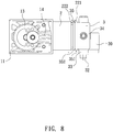
- an air compressor according to one embodiment of the present invention is shown, which generally comprises a cylinder 2 fitted with a piston body 14, and a main frame 11 for mounting a motor 12 which can rotate a gear 13 to drive the piston body 14 to conduct reciprocating motion for producing compressed air in the cylinder, which may enter an air storage container 3 provided with one or more outlets for supplying air to various devices.
- the outlet 31 can be used for connecting with a pressure gauge 30, the outlet 33 can be used for connecting with a relief valve 32, and the outlet 34 can be connected with a hose for inflating an object (not shown).
- the air compressor is designed in a way different from conventional technology.
- the cylinder 2, which defines three exit holes 4, 5, 6 at its top wall 21, is formed integrally with the main frame 11 by plastic material.
- the exit holes 4, 5, 6 are approximately equal in dimension.
- the exit hole 4 is defined to have a diameter of (X)
- the exit hole 5 is defined to have a diameter of (Y)
- the exit holes 4, 5, 6 are regulated by a control mechanism to be opened or closed.
- the control mechanism includes a plurality of plugs 7, 8, 9 and a plurality of compression springs 71, 81, 91, corresponding to plugs 7, 8, 9.
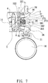
- the compression springs 71, 81, 91 can urge the plugs 7, 8, 9 to seal the exit holes 4, 5, 6, respectively (see FIGS 2 , 4 and 7 ).
- the cylinder 2 has a tubular projection 22 formed on the top wall 21.
- the tubular projection 22 is provided with a circular flange 221 at its outer surface and defines an annular groove 222 between the circular flange 221 and the top wall 21.
- the air storage container 3 is provided with two opposite coupling means 35 (see FIG.
- each of which includes a base portion 351 extending outwardly from a bottom edge of the air storage container 3, and an L-shaped holding portion 352 integrally formed at one end of the base portion 351 distal from the bottom edge of the air storage container 3. Furthermore, the air storage container 3 is provided at an inner surface thereof with a plurality of columns 37, 38, 39 corresponding to the compression springs 71, 81, 91.
- the column 37 has a base round portion 371, a middle round portion 372, and an end round portion 373;
- the column 38 has a base round portion 381, a middle round portion 382, and an end round portion 383;
- the column 39 has a base round portion 391, a middle round portion 392, and an end round portion 393; wherein the diameter of the base round portion 371, 381 or 391 is greater than that of the corresponding middle round portion 372, 382 or 392, and the diameter of the middle round portion 372, 382 or 392 is greater than that of the corresponding end round portion 373, 383 or 393.
- each of the compression springs 71, 81, 91 has one end forcing against the corresponding plug 7, 8 or 9, and has another end being fitted around the middle round portion 372, 382 or 392 of the corresponding column and forcing against the base round portion 371, 381 or 391 of the corresponding column.
- Each of the end round portions 373, 383, 393 of the columns 37, 38, 39 is located at a predetermined height above the corresponding plug so as to limit the movement of the corresponding plug.
- FIG. 1 shows the air storage container 3 being assembled onto the cylinder 2.
- the compressed air produced in the cylinder 2 can overcome the force of the compression springs 71, 81, 91 exerted on the plugs 7, 8, 9, thus pushing the plugs 7, 8, 9 away from the exit holes 4, 5, 6, respectively, so that the compressed air can flow into the inner space 36 of the air storage container 3.
- the air storage container 3 can be filled with a large amount of air in a short time.
- the air contained in the air storage container 3 can exert a greater back force on the plugs 7, 8, 9 compared to the air initially contained in the air storage container 3.
- the piston body 14 may experience greater resistance in conducting reciprocating motion, and thus may cause the exit holes 4, 5, 6 more difficult to be opened.
- the back force exerted on the plugs 7, 8, 9 will decrease and this allows the compressed air produced in the cylinder 2 to quickly enter the inner space 36 of the air storage container 3.
- the performance of the air compressor can be increased.
- the air compressor can inflate an object more quickly.
- FIG. 9 shows another embodiment of the present invention, wherein the tubular projection 22 is provided at its outer surface with two opposite lugs 23 each having an engagement section 231.
- the L-shaped holding portions 352 of the two coupling means 35 can engage with the engagement sections 231 of the two lugs 23, so that the air storage container 3 can be detachably assembled onto the cylinder 2.
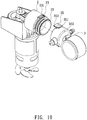
- FIG. 10 shows a further embodiment of the present invention, wherein the tubular projection 22 is provided at its outer surface with two opposite lugs 23 each having an engagement section 231.
- the L-shaped holding portions 352 of the two coupling means 35 can engage with the engagement sections 231 of the two lugs 23, so that the air storage container 3 can be detachably assembled onto the cylinder 2.
- each of the two coupling means 35 further includes an operation portion 353, which is a resilient member and integrally formed at one end of the base portion 351 distal from the bottom edge of the air storage container 3 and located at a side of the base portion 351 opposite to the L-shaped holding portion 352.
- a user may depress the operation portions 353 to have the L-shaped holding portions 352 disengaged from the lugs 23, so that the air storage container 3 can be dissembled from the cylinder 2 conveniently when maintenance is required.
- FIG. 11 shows a still further embodiment of the present invention, wherein the tubular projection 22 is provided at its outer surface with two opposite lugs 23 each having an engagement section 231.
- the L-shaped holding portions 352 of the two coupling means 35 can engage with the engagement sections 231 of the two lugs 23, so that the air storage container 3 can be detachably assembled onto the cylinder 2.
- each of the two coupling means 35 further includes an operation portion 354, which is a resilient member and extends from the L-shaped holding portion 352 in a direction opposite to the base portion 351.
- a user may pull the operation portions 354 outwardly from the cylinder 2 to have the L-shaped holding portions 352 disengaged from the lugs 23, so that the air storage container 3 can be dissembled from the cylinder 2 easily when maintenance is required.
- FIG. 12 shows a yet still further embodiment of the present invention, wherein the tubular projection 22 is provided at its outer surface with two opposite lugs 23 each having an engagement section 231.
- the tubular projection 22 is further provided at its outer surface with a first rectangular flange 24 which defines a plurality of positioning holes 240.
- the air storage container 3 is further provided at its bottom edge with a second rectangular flange 355 which defines a plurality of positioning holes 356 corresponding to the positioning holes 240 of the first rectangular flange 24.
- the first and second flanges 24, 355 can be attached together by fasteners fitted through the first and second positioning holes 240, 356. As such, the air storage container 3 can be assembled onto the cylinder 2 more securely.
- the air compressor of the present invention has a breakthrough over the prior art in that the top wall 21 of the cylinder 2 defines a plurality of exit holes 4, 5, 6, which are approximately equal in dimension and controlled by the plugs 7, 8, 9 to allow the compressed air produced in the cylinder 2 to quickly enter the inner space 36 of the air storage container 3, so that the piston body 14 can conduct reciprocating motion more smoothly and thus the performance of the air compressor can be increased.
Claims (8)
- Luftkompressor, der einen Hauptrahmen (11) zum Anbringen eines Motors (12) umfasst, der ein Getriebe dreht, um einen in einen Zylinder (2) eingepassten Kolbenkörper (14) anzutreiben, um eine Pendelbewegung zur Erzeugung von Druckluft auszuführen, die in einen Innenraum (36) eines Luftspeicherbehälters (3) eindringt, wobei der Zylinder (2) an seiner oberen Wand (21) eine Vielzahl von Austrittslöchern (4, 5, 6) mit gleicher Dimension definiert, wobei die Austrittslöcher (4, 5, 6) von einem Steuermechanismus gesteuert werden, um geöffnet oder geschlossen zu werden, wobei der Steuermechanismus eine Vielzahl an Stopfen und eine Vielzahl an Kompressionsfedern umfasst, die entsprechend die Stopfen dazu bringen können, die Austrittslöcher zu verschließen,
dadurch gekennzeichnet, dass
der Luftspeicherbehälter (3) an seiner unteren Kante mit zwei entgegengesetzten Kopplungsmitteln (35) ausgestattet ist, wobei jedes Kopplungsmittel einen Basisabschnitt (351), der sich von dem unteren Rand des Luftspeicherbehälters (3) nach außen erstreckt, und einen L-förmigen Halteabschnitt (352) beinhaltet, der an einem Ende des Basisabschnitts (351), das von dem unteren Rand des Luftspeicherbehälters (3) entfernt ist, einstückig ausgebildet ist. - Luftkompressor nach Anspruch 1, bei dem der Zylinder (2), der die Austrittslöcher (4, 5, 6) definiert, einstückig mit dem Hauptrahmen (11) durch Kunststoffmaterial ausgebildet ist.
- Luftkompressor nach Anspruch 1, bei dem die Austrittslöcher (4, 5, 6) so definiert sind, dass sie den gleichen Durchmesser aufweisen.
- Luftkompressor nach Anspruch 1, bei dem der Zylinder (2) einen rohrförmigen Vorsprung (22) aufweist, der an der oberen Wand (21) ausgebildet ist, wobei der rohrförmige Vorsprung (22) an seiner Außenfläche mit einem kreisförmigen Flansch (221) versehen ist und eine ringförmige Nut (222) zwischen dem kreisförmigen Flansch (221) und der oberen Wand (21) ausbildet, damit die L-förmigen Halteabschnitte (352) des Luftspeicherbehälters (3) in die ringförmige Nut (222) eingeführt und mit dem kreisförmigen Flansch (221) in Eingriff gebracht werden können, so dass der Luftspeicherbehälter (3) lösbar auf dem Zylinder (2) montiert werden kann, wobei der Luftspeicherbehälter (3) an seiner Innenfläche mit einer Vielzahl an Säulen (37, 38, 39) versehen ist, die den Kompressionsfedern (71, 81, 91) entsprechen, wobei jede der Säulen (37, 38, 39) einen runden Basisabschnitt (371, 381, 391), einen runden Mittelabschnitt (372, 382, 392) und einen runden Endabschnitt (373, 383, 393) aufweist, wobei jede der Kompressionsfedern (71, 81, 91) ein Ende aufweist, das gegen den entsprechenden Stopfen drückt, und ein anderes Ende, das um den mittleren runden Abschnitt der entsprechenden Säule herum angebracht ist und gegen den unteren runden Abschnitt der entsprechenden Säule drückt, wobei jeder der runden Endabschnitte der Säulen sich in einer vorbestimmten Höhe über dem entsprechenden Stopfen befindet, um die Bewegung des entsprechenden Stopfens zu begrenzen.
- Luftkompressor nach Anspruch 1, bei dem der Zylinder (2) einen rohrförmigen Vorsprung (22) aufweist, der an der oberen Wand (21) ausgebildet ist, wobei der rohrförmige Vorsprung (22) an seiner Außenfläche mit zwei gegenüberliegenden Ansätzen (23) versehen ist, die jeweils einen Eingriffsabschnitt (231) aufweisen, wobei die L-förmigen Halteabschnitte (352) der beiden Kupplungsmittel (35) mit den Eingriffsabschnitten (231) der beiden Ansätze (23) in Eingriff kommen können, so dass der Luftspeicherbehälter lösbar auf den Zylinder (2) montiert sein kann.
- Luftkompressor nach Anspruch 1, bei dem der Zylinder (2) einen rohrförmigen Vorsprung (22) aufweist, der an der oberen Wand (21) ausgebildet ist, wobei der rohrförmige Vorsprung (22) an seiner Außenfläche mit zwei gegenüberliegenden Ansätzen (23) versehen ist, die jeweils einen Eingriffsabschnitt (231) aufweisen, wobei die L-förmigen Halteabschnitte (352) der beiden Kopplungsmittel (35) mit den Eingriffsabschnitten (231) der beiden Ansätze (23) in Eingriff kommen können, wobei jedes der beiden Kopplungsmittel (35) ferner einen Betätigungsabschnitt (353) umfasst, der einstückig an einem Ende des Basisabschnitts (351) ausgebildet ist, das von dem Rand des Bodens des Luftspeicherbehälters (3) entfernt ist und sich an einer Seite des Basisabschnitts (351) befindet, die dem L-förmigen Halteabschnitt (352) gegenüberliegt, so dass der Luftvorratsbehälter (3) abnehmbar und zweckmäßig an dem Zylinder (2) montiert werden kann.
- Luftkompressor nach Anspruch 1; bei dem der Zylinder (2) einen rohrförmigen Vorsprung (22) aufweist, der an der oberen Wand (21) ausgebildet ist, wobei der rohrförmige Vorsprung (22) an seiner Außenfläche mit zwei gegenüberliegenden Ansätzen (23) versehen ist, die jeweils einen Eingriffsabschnitt (231) aufweisen, wobei die L-förmigen Halteabschnitte (352) der beiden Kopplungsmittel (35) mit den Eingriffsabschnitten (231) der beiden Ansätze (23) in Eingriff kommen können, wobei jedes der beiden Kopplungsmittel (35) ferner einen Betätigungsabschnitt (354) umfasst, der sich von dem L-förmigen Halteabschnitt (352) in einer Richtung entgegengesetzt zu dem Basisabschnitt (351) erstreckt, so dass der Luftspeicherbehälter (3) abnehmbar und zweckmäßig an dem Zylinder (2) montiert werden kann.
- Luftkompressor nach Anspruch 1, bei dem der Zylinder (2) einen rohrförmigen Vorsprung (22) aufweist, der an der oberen Wand (21) ausgebildet ist, wobei der rohrförmige Vorsprung (22) an seiner Außenfläche mit zwei gegenüberliegenden Ansätzen (23) versehen ist, die jeweils einen Eingriffsabschnitt (231) aufweisen, wobei die L-förmigen Halteabschnitte (352) der beiden Kupplungsmittel (35) mit den Eingriffsabschnitten (231) der beiden Ansätze (23) in Eingriff kommen können, wobei der rohrförmige Vorsprung (22) ferner an seiner Außenfläche mit einem ersten rechteckigen Flansch (24) ausgestattet ist, der eine Vielzahl an Positionierlöchern (240) definiert, wobei der Luftspeicherbehälter (3) ferner an seiner Unterkante mit einem zweiten rechteckigen Flansch (355) ausgestattet ist, der eine Vielzahl an Positionierlöchern (356) definiert, die den Positionierlöchern (240) des ersten rechteckigen Flansches (24) entsprechen, so dass der Luftspeicherbehälter (3) lösbar und sicher an dem Zylinder (2) montiert werden kann.
Priority Applications (1)
| Application Number | Priority Date | Filing Date | Title |
|---|---|---|---|
| PL17151528T PL3214309T3 (pl) | 2016-01-14 | 2017-01-13 | Ulepszona sprężarka powietrza |
Applications Claiming Priority (1)
| Application Number | Priority Date | Filing Date | Title |
|---|---|---|---|
| TW105101152A TWI617741B (zh) | 2016-01-14 | 2016-01-14 | 空氣壓縮機之汽缸出氣構造改良 |
Publications (3)
| Publication Number | Publication Date |
|---|---|
| EP3214309A2 EP3214309A2 (de) | 2017-09-06 |
| EP3214309A3 EP3214309A3 (de) | 2017-12-27 |
| EP3214309B1 true EP3214309B1 (de) | 2020-03-04 |
Family
ID=57796282
Family Applications (1)
| Application Number | Title | Priority Date | Filing Date |
|---|---|---|---|
| EP17151528.1A Active EP3214309B1 (de) | 2016-01-14 | 2017-01-13 | Verbesserter luftkompressor |
Country Status (10)
| Country | Link |
|---|---|
| US (1) | US10385848B2 (de) |
| EP (1) | EP3214309B1 (de) |
| JP (2) | JP3209542U (de) |
| KR (1) | KR101907148B1 (de) |
| CN (2) | CN206636741U (de) |
| DE (1) | DE202017100185U1 (de) |
| DK (1) | DK3214309T3 (de) |
| HU (1) | HUE049994T2 (de) |
| PL (1) | PL3214309T3 (de) |
| TW (1) | TWI617741B (de) |
Families Citing this family (3)
| Publication number | Priority date | Publication date | Assignee | Title |
|---|---|---|---|---|
| TWI621776B (zh) * | 2016-01-15 | 2018-04-21 | Wen-San Chou | 空壓機之汽缸出氣構造改良 |
| TWI687602B (zh) * | 2018-08-09 | 2020-03-11 | 已久工業股份有限公司 | 空氣壓縮機之防脫落的軸承結構 |
| TWI785623B (zh) * | 2021-05-24 | 2022-12-01 | 周文三 | 空壓機之馬達結合定位裝置 |
Family Cites Families (33)
| Publication number | Priority date | Publication date | Assignee | Title |
|---|---|---|---|---|
| AT251178B (de) * | 1965-07-02 | 1966-12-27 | Hoerbiger Ventilwerke Ag | Ventilsatz für Kolbenverdichter |
| US4385872A (en) * | 1980-01-22 | 1983-05-31 | Copeland Corporation | Compressor |
| US4542768A (en) * | 1984-03-12 | 1985-09-24 | Rotron, Inc. | Pressure relief valve |
| IT1192022B (it) * | 1986-04-28 | 1988-03-31 | Fini Elettrocostruzioni Mecc S | Valvola di tipo perfezionato particolarmente per compressori d'aria |
| US4854839A (en) * | 1988-06-13 | 1989-08-08 | Copeland Corporation | Compressor valve assembly |
| US4957419A (en) * | 1989-04-14 | 1990-09-18 | Rascov Anthony J | Compressor |
| JP3198151B2 (ja) * | 1991-11-20 | 2001-08-13 | 三菱製紙株式会社 | マイクロカプセルの連続製造法 |
| US5562431A (en) * | 1995-05-10 | 1996-10-08 | Ingersoll-Rand Company | Isolated backstop for flexible compressor valve |
| US6942472B2 (en) * | 2002-03-29 | 2005-09-13 | Devilbiss Air Power Company | Head pressure relief assembly |
| JP2006526112A (ja) * | 2003-05-14 | 2006-11-16 | ユソン エンタープライズ カンパニー リミテッド | エアコンプレッサ |
| JP4566676B2 (ja) * | 2004-09-30 | 2010-10-20 | 日立オートモティブシステムズ株式会社 | 空気圧縮機 |
| KR100774485B1 (ko) * | 2005-08-26 | 2007-11-08 | 엘지전자 주식회사 | 압축기 |
| CN101240786B (zh) * | 2007-02-05 | 2011-09-07 | 周文三 | 空气压缩机的结合构造 |
| US20090028733A1 (en) * | 2007-07-25 | 2009-01-29 | Freudenberg-Nok General Partnership | Compressor Valve Plate Assembly with Integrated Gasket |
| CN101403376B (zh) * | 2008-11-10 | 2010-10-20 | 周文三 | 空压机 |
| CN201739125U (zh) * | 2010-06-02 | 2011-02-09 | 常州市昊升电机有限公司 | 微型气泵 |
| CN201786631U (zh) * | 2010-06-25 | 2011-04-06 | 厦门阳铭工贸有限公司 | 隔膜气泵密封结构 |
| CN101936277A (zh) * | 2010-08-03 | 2011-01-05 | 快意(江门)压缩机有限公司 | 一种紧凑型环保无油空气压缩机 |
| JP2012158087A (ja) * | 2011-01-31 | 2012-08-23 | Bridgestone Corp | タイヤ昇圧装置 |
| AU2012216658B2 (en) * | 2011-09-13 | 2016-09-15 | Black & Decker Inc | Method of reducing air compressor noise |
| US9637283B2 (en) * | 2012-06-15 | 2017-05-02 | Stephen B. Maguire | Quarter turn adapter connective outlet fitting for liquid color dispensing |
| WO2014056133A1 (zh) * | 2012-10-08 | 2014-04-17 | 冠翔(香港)工业有限公司 | 空气压缩机 |
| US20140286804A1 (en) * | 2013-03-20 | 2014-09-25 | Wen San Chou | Air compressor having buffering compartment |
| CN203430735U (zh) * | 2013-08-09 | 2014-02-12 | 厦门科际精密器材有限公司 | 低噪音气泵 |
| KR200477700Y1 (ko) * | 2014-02-10 | 2015-07-09 | 대상 주식회사 | 식품 용기의 마개 |
| TWI545262B (zh) * | 2014-04-07 | 2016-08-11 | 周文三 | 空氣壓縮機 |
| TWI545258B (zh) * | 2014-04-07 | 2016-08-11 | 周文三 | 空氣壓縮機 |
| CA2945378C (en) * | 2014-04-16 | 2023-04-25 | Gojo Industries, Inc. | Mini pump with compressible air inlet chamber for providing residual suck-back |
| TWI604129B (zh) * | 2014-04-22 | 2017-11-01 | 周文三 | 空氣壓縮機 |
| CN203925927U (zh) * | 2014-05-06 | 2014-11-05 | 周文三 | 空气压缩机 |
| TWI576514B (zh) * | 2014-10-01 | 2017-04-01 | 周文三 | 空氣壓縮機之改良構造 |
| TWM498680U (zh) * | 2014-11-20 | 2015-04-11 | ming-xian Wang | 具充氣及補胎之空壓機 |
| CN104912773B (zh) * | 2015-07-01 | 2017-10-24 | 浙江申元机电有限公司 | 一种空气压缩装置及空压机 |
-
2016
- 2016-01-14 TW TW105101152A patent/TWI617741B/zh active
-
2017
- 2017-01-09 KR KR1020170002992A patent/KR101907148B1/ko active IP Right Grant
- 2017-01-10 US US15/402,246 patent/US10385848B2/en active Active
- 2017-01-12 CN CN201720034581.XU patent/CN206636741U/zh not_active Expired - Fee Related
- 2017-01-12 JP JP2017000058U patent/JP3209542U/ja active Active
- 2017-01-12 JP JP2017003008A patent/JP6446480B2/ja active Active
- 2017-01-12 CN CN201710021872.XA patent/CN106968921B/zh active Active
- 2017-01-13 EP EP17151528.1A patent/EP3214309B1/de active Active
- 2017-01-13 PL PL17151528T patent/PL3214309T3/pl unknown
- 2017-01-13 DE DE202017100185.7U patent/DE202017100185U1/de not_active Expired - Lifetime
- 2017-01-13 DK DK17151528.1T patent/DK3214309T3/da active
- 2017-01-13 HU HUE17151528A patent/HUE049994T2/hu unknown
Non-Patent Citations (1)
| Title |
|---|
| None * |
Also Published As
| Publication number | Publication date |
|---|---|
| CN106968921B (zh) | 2019-04-30 |
| JP3209542U (ja) | 2017-03-23 |
| HUE049994T2 (hu) | 2020-11-30 |
| DK3214309T3 (da) | 2020-06-08 |
| EP3214309A3 (de) | 2017-12-27 |
| KR20170085438A (ko) | 2017-07-24 |
| JP2017125503A (ja) | 2017-07-20 |
| JP6446480B2 (ja) | 2018-12-26 |
| DE202017100185U1 (de) | 2017-01-25 |
| CN206636741U (zh) | 2017-11-14 |
| US10385848B2 (en) | 2019-08-20 |
| TWI617741B (zh) | 2018-03-11 |
| EP3214309A2 (de) | 2017-09-06 |
| US20170204845A1 (en) | 2017-07-20 |
| CN106968921A (zh) | 2017-07-21 |
| PL3214309T3 (pl) | 2020-09-07 |
| KR101907148B1 (ko) | 2018-10-12 |
| TW201725323A (zh) | 2017-07-16 |
Similar Documents
| Publication | Publication Date | Title |
|---|---|---|
| EP2930361B1 (de) | Luftkompressor | |
| EP3214309B1 (de) | Verbesserter luftkompressor | |
| EP3196463B1 (de) | Verbesserter luftkompressor | |
| EP2937568B1 (de) | Luftkompressor | |
| EP2930362B1 (de) | Luftkompressor | |
| US11148312B2 (en) | Hydraulic hand-held knockout punch driver | |
| EP3193016B1 (de) | Verbesserter luftkompressor | |
| US10294932B2 (en) | Air compressor | |
| US10132310B2 (en) | Air compressor | |
| US10138878B2 (en) | Air compressor | |
| EP3211234B1 (de) | Verbesserter luftkompressor | |
| EP3193018B1 (de) | Verbesserter luftkompressor | |
| JP6260459B2 (ja) | 打込機 | |
| KR20150110503A (ko) | 공기압축기 장치 |
Legal Events
| Date | Code | Title | Description |
|---|---|---|---|
| PUAI | Public reference made under article 153(3) epc to a published international application that has entered the european phase |
Free format text: ORIGINAL CODE: 0009012 |
|
| STAA | Information on the status of an ep patent application or granted ep patent |
Free format text: STATUS: THE APPLICATION HAS BEEN PUBLISHED |
|
| AK | Designated contracting states |
Kind code of ref document: A2 Designated state(s): AL AT BE BG CH CY CZ DE DK EE ES FI FR GB GR HR HU IE IS IT LI LT LU LV MC MK MT NL NO PL PT RO RS SE SI SK SM TR |
|
| AX | Request for extension of the european patent |
Extension state: BA ME |
|
| PUAL | Search report despatched |
Free format text: ORIGINAL CODE: 0009013 |
|
| AK | Designated contracting states |
Kind code of ref document: A3 Designated state(s): AL AT BE BG CH CY CZ DE DK EE ES FI FR GB GR HR HU IE IS IT LI LT LU LV MC MK MT NL NO PL PT RO RS SE SI SK SM TR |
|
| AX | Request for extension of the european patent |
Extension state: BA ME |
|
| RIC1 | Information provided on ipc code assigned before grant |
Ipc: F04B 39/10 20060101AFI20171122BHEP Ipc: F04B 39/12 20060101ALI20171122BHEP Ipc: F04B 35/04 20060101ALI20171122BHEP |
|
| STAA | Information on the status of an ep patent application or granted ep patent |
Free format text: STATUS: REQUEST FOR EXAMINATION WAS MADE |
|
| 17P | Request for examination filed |
Effective date: 20180329 |
|
| RBV | Designated contracting states (corrected) |
Designated state(s): AL AT BE BG CH CY CZ DE DK EE ES FI FR GB GR HR HU IE IS IT LI LT LU LV MC MK MT NL NO PL PT RO RS SE SI SK SM TR |
|
| GRAP | Despatch of communication of intention to grant a patent |
Free format text: ORIGINAL CODE: EPIDOSNIGR1 |
|
| STAA | Information on the status of an ep patent application or granted ep patent |
Free format text: STATUS: GRANT OF PATENT IS INTENDED |
|
| INTG | Intention to grant announced |
Effective date: 20190806 |
|
| GRAS | Grant fee paid |
Free format text: ORIGINAL CODE: EPIDOSNIGR3 |
|
| GRAA | (expected) grant |
Free format text: ORIGINAL CODE: 0009210 |
|
| STAA | Information on the status of an ep patent application or granted ep patent |
Free format text: STATUS: THE PATENT HAS BEEN GRANTED |
|
| AK | Designated contracting states |
Kind code of ref document: B1 Designated state(s): AL AT BE BG CH CY CZ DE DK EE ES FI FR GB GR HR HU IE IS IT LI LT LU LV MC MK MT NL NO PL PT RO RS SE SI SK SM TR |
|
| REG | Reference to a national code |
Ref country code: GB Ref legal event code: FG4D |
|
| REG | Reference to a national code |
Ref country code: CH Ref legal event code: EP |
|
| REG | Reference to a national code |
Ref country code: AT Ref legal event code: REF Ref document number: 1240669 Country of ref document: AT Kind code of ref document: T Effective date: 20200315 |
|
| REG | Reference to a national code |
Ref country code: DE Ref legal event code: R096 Ref document number: 602017012426 Country of ref document: DE |
|
| REG | Reference to a national code |
Ref country code: IE Ref legal event code: FG4D |
|
| REG | Reference to a national code |
Ref country code: DK Ref legal event code: T3 Effective date: 20200603 |
|
| REG | Reference to a national code |
Ref country code: NL Ref legal event code: FP |
|
| REG | Reference to a national code |
Ref country code: SE Ref legal event code: TRGR |
|
| PG25 | Lapsed in a contracting state [announced via postgrant information from national office to epo] |
Ref country code: NO Free format text: LAPSE BECAUSE OF FAILURE TO SUBMIT A TRANSLATION OF THE DESCRIPTION OR TO PAY THE FEE WITHIN THE PRESCRIBED TIME-LIMIT Effective date: 20200604 Ref country code: FI Free format text: LAPSE BECAUSE OF FAILURE TO SUBMIT A TRANSLATION OF THE DESCRIPTION OR TO PAY THE FEE WITHIN THE PRESCRIBED TIME-LIMIT Effective date: 20200304 Ref country code: RS Free format text: LAPSE BECAUSE OF FAILURE TO SUBMIT A TRANSLATION OF THE DESCRIPTION OR TO PAY THE FEE WITHIN THE PRESCRIBED TIME-LIMIT Effective date: 20200304 |
|
| PG25 | Lapsed in a contracting state [announced via postgrant information from national office to epo] |
Ref country code: HR Free format text: LAPSE BECAUSE OF FAILURE TO SUBMIT A TRANSLATION OF THE DESCRIPTION OR TO PAY THE FEE WITHIN THE PRESCRIBED TIME-LIMIT Effective date: 20200304 Ref country code: GR Free format text: LAPSE BECAUSE OF FAILURE TO SUBMIT A TRANSLATION OF THE DESCRIPTION OR TO PAY THE FEE WITHIN THE PRESCRIBED TIME-LIMIT Effective date: 20200605 Ref country code: BG Free format text: LAPSE BECAUSE OF FAILURE TO SUBMIT A TRANSLATION OF THE DESCRIPTION OR TO PAY THE FEE WITHIN THE PRESCRIBED TIME-LIMIT Effective date: 20200604 Ref country code: LV Free format text: LAPSE BECAUSE OF FAILURE TO SUBMIT A TRANSLATION OF THE DESCRIPTION OR TO PAY THE FEE WITHIN THE PRESCRIBED TIME-LIMIT Effective date: 20200304 |
|
| REG | Reference to a national code |
Ref country code: LT Ref legal event code: MG4D |
|
| PG25 | Lapsed in a contracting state [announced via postgrant information from national office to epo] |
Ref country code: ES Free format text: LAPSE BECAUSE OF FAILURE TO SUBMIT A TRANSLATION OF THE DESCRIPTION OR TO PAY THE FEE WITHIN THE PRESCRIBED TIME-LIMIT Effective date: 20200304 Ref country code: LT Free format text: LAPSE BECAUSE OF FAILURE TO SUBMIT A TRANSLATION OF THE DESCRIPTION OR TO PAY THE FEE WITHIN THE PRESCRIBED TIME-LIMIT Effective date: 20200304 Ref country code: PT Free format text: LAPSE BECAUSE OF FAILURE TO SUBMIT A TRANSLATION OF THE DESCRIPTION OR TO PAY THE FEE WITHIN THE PRESCRIBED TIME-LIMIT Effective date: 20200729 Ref country code: SM Free format text: LAPSE BECAUSE OF FAILURE TO SUBMIT A TRANSLATION OF THE DESCRIPTION OR TO PAY THE FEE WITHIN THE PRESCRIBED TIME-LIMIT Effective date: 20200304 Ref country code: EE Free format text: LAPSE BECAUSE OF FAILURE TO SUBMIT A TRANSLATION OF THE DESCRIPTION OR TO PAY THE FEE WITHIN THE PRESCRIBED TIME-LIMIT Effective date: 20200304 Ref country code: IS Free format text: LAPSE BECAUSE OF FAILURE TO SUBMIT A TRANSLATION OF THE DESCRIPTION OR TO PAY THE FEE WITHIN THE PRESCRIBED TIME-LIMIT Effective date: 20200704 Ref country code: RO Free format text: LAPSE BECAUSE OF FAILURE TO SUBMIT A TRANSLATION OF THE DESCRIPTION OR TO PAY THE FEE WITHIN THE PRESCRIBED TIME-LIMIT Effective date: 20200304 Ref country code: SK Free format text: LAPSE BECAUSE OF FAILURE TO SUBMIT A TRANSLATION OF THE DESCRIPTION OR TO PAY THE FEE WITHIN THE PRESCRIBED TIME-LIMIT Effective date: 20200304 |
|
| REG | Reference to a national code |
Ref country code: HU Ref legal event code: AG4A Ref document number: E049994 Country of ref document: HU |
|
| REG | Reference to a national code |
Ref country code: DE Ref legal event code: R097 Ref document number: 602017012426 Country of ref document: DE |
|
| PLBE | No opposition filed within time limit |
Free format text: ORIGINAL CODE: 0009261 |
|
| STAA | Information on the status of an ep patent application or granted ep patent |
Free format text: STATUS: NO OPPOSITION FILED WITHIN TIME LIMIT |
|
| 26N | No opposition filed |
Effective date: 20201207 |
|
| PG25 | Lapsed in a contracting state [announced via postgrant information from national office to epo] |
Ref country code: SI Free format text: LAPSE BECAUSE OF FAILURE TO SUBMIT A TRANSLATION OF THE DESCRIPTION OR TO PAY THE FEE WITHIN THE PRESCRIBED TIME-LIMIT Effective date: 20200304 |
|
| PG25 | Lapsed in a contracting state [announced via postgrant information from national office to epo] |
Ref country code: MC Free format text: LAPSE BECAUSE OF FAILURE TO SUBMIT A TRANSLATION OF THE DESCRIPTION OR TO PAY THE FEE WITHIN THE PRESCRIBED TIME-LIMIT Effective date: 20200304 |
|
| REG | Reference to a national code |
Ref country code: CH Ref legal event code: PL |
|
| PG25 | Lapsed in a contracting state [announced via postgrant information from national office to epo] |
Ref country code: LU Free format text: LAPSE BECAUSE OF NON-PAYMENT OF DUE FEES Effective date: 20210113 |
|
| PG25 | Lapsed in a contracting state [announced via postgrant information from national office to epo] |
Ref country code: CH Free format text: LAPSE BECAUSE OF NON-PAYMENT OF DUE FEES Effective date: 20210131 Ref country code: LI Free format text: LAPSE BECAUSE OF NON-PAYMENT OF DUE FEES Effective date: 20210131 |
|
| PG25 | Lapsed in a contracting state [announced via postgrant information from national office to epo] |
Ref country code: IE Free format text: LAPSE BECAUSE OF NON-PAYMENT OF DUE FEES Effective date: 20210113 |
|
| PGFP | Annual fee paid to national office [announced via postgrant information from national office to epo] |
Ref country code: CZ Payment date: 20211210 Year of fee payment: 6 |
|
| PGFP | Annual fee paid to national office [announced via postgrant information from national office to epo] |
Ref country code: PL Payment date: 20211210 Year of fee payment: 6 |
|
| PGFP | Annual fee paid to national office [announced via postgrant information from national office to epo] |
Ref country code: HU Payment date: 20220105 Year of fee payment: 6 Ref country code: GB Payment date: 20220125 Year of fee payment: 6 Ref country code: DK Payment date: 20220121 Year of fee payment: 6 Ref country code: AT Payment date: 20220119 Year of fee payment: 6 |
|
| PGFP | Annual fee paid to national office [announced via postgrant information from national office to epo] |
Ref country code: TR Payment date: 20220106 Year of fee payment: 6 Ref country code: SE Payment date: 20220125 Year of fee payment: 6 Ref country code: NL Payment date: 20220120 Year of fee payment: 6 Ref country code: IT Payment date: 20220124 Year of fee payment: 6 Ref country code: FR Payment date: 20220120 Year of fee payment: 6 Ref country code: BE Payment date: 20220120 Year of fee payment: 6 |
|
| PG25 | Lapsed in a contracting state [announced via postgrant information from national office to epo] |
Ref country code: CY Free format text: LAPSE BECAUSE OF FAILURE TO SUBMIT A TRANSLATION OF THE DESCRIPTION OR TO PAY THE FEE WITHIN THE PRESCRIBED TIME-LIMIT Effective date: 20200304 |
|
| REG | Reference to a national code |
Ref country code: DK Ref legal event code: EBP Effective date: 20230131 |
|
| REG | Reference to a national code |
Ref country code: SE Ref legal event code: EUG |
|
| REG | Reference to a national code |
Ref country code: NL Ref legal event code: MM Effective date: 20230201 |
|
| REG | Reference to a national code |
Ref country code: AT Ref legal event code: MM01 Ref document number: 1240669 Country of ref document: AT Kind code of ref document: T Effective date: 20230113 |
|
| GBPC | Gb: european patent ceased through non-payment of renewal fee |
Effective date: 20230113 |
|
| REG | Reference to a national code |
Ref country code: BE Ref legal event code: MM Effective date: 20230131 |
|
| PG25 | Lapsed in a contracting state [announced via postgrant information from national office to epo] |
Ref country code: SE Free format text: LAPSE BECAUSE OF NON-PAYMENT OF DUE FEES Effective date: 20230114 Ref country code: NL Free format text: LAPSE BECAUSE OF NON-PAYMENT OF DUE FEES Effective date: 20230201 Ref country code: GB Free format text: LAPSE BECAUSE OF NON-PAYMENT OF DUE FEES Effective date: 20230113 Ref country code: CZ Free format text: LAPSE BECAUSE OF NON-PAYMENT OF DUE FEES Effective date: 20230113 Ref country code: AT Free format text: LAPSE BECAUSE OF NON-PAYMENT OF DUE FEES Effective date: 20230113 |
|
| PG25 | Lapsed in a contracting state [announced via postgrant information from national office to epo] |
Ref country code: HU Free format text: LAPSE BECAUSE OF NON-PAYMENT OF DUE FEES Effective date: 20230114 Ref country code: FR Free format text: LAPSE BECAUSE OF NON-PAYMENT OF DUE FEES Effective date: 20230131 Ref country code: BE Free format text: LAPSE BECAUSE OF NON-PAYMENT OF DUE FEES Effective date: 20230131 |
|
| PG25 | Lapsed in a contracting state [announced via postgrant information from national office to epo] |
Ref country code: IT Free format text: LAPSE BECAUSE OF NON-PAYMENT OF DUE FEES Effective date: 20230113 Ref country code: DK Free format text: LAPSE BECAUSE OF NON-PAYMENT OF DUE FEES Effective date: 20230131 |
|
| PG25 | Lapsed in a contracting state [announced via postgrant information from national office to epo] |
Ref country code: MK Free format text: LAPSE BECAUSE OF FAILURE TO SUBMIT A TRANSLATION OF THE DESCRIPTION OR TO PAY THE FEE WITHIN THE PRESCRIBED TIME-LIMIT Effective date: 20200304 |
|
| PGFP | Annual fee paid to national office [announced via postgrant information from national office to epo] |
Ref country code: DE Payment date: 20240122 Year of fee payment: 8 |