EP3213789B2 - Ventil - Google Patents
Ventil Download PDFInfo
- Publication number
- EP3213789B2 EP3213789B2 EP16158227.5A EP16158227A EP3213789B2 EP 3213789 B2 EP3213789 B2 EP 3213789B2 EP 16158227 A EP16158227 A EP 16158227A EP 3213789 B2 EP3213789 B2 EP 3213789B2
- Authority
- EP
- European Patent Office
- Prior art keywords
- valve
- wall
- area
- reinforcement
- slit
- Prior art date
- Legal status (The legal status is an assumption and is not a legal conclusion. Google has not performed a legal analysis and makes no representation as to the accuracy of the status listed.)
- Active
Links
- 210000003323 beak Anatomy 0.000 claims description 44
- 239000000463 material Substances 0.000 claims description 24
- 230000003014 reinforcing effect Effects 0.000 claims description 9
- 239000012530 fluid Substances 0.000 claims description 8
- 230000001012 protector Effects 0.000 claims 4
- 241000272525 Anas platyrhynchos Species 0.000 claims 1
- 230000002787 reinforcement Effects 0.000 description 113
- HVCNNTAUBZIYCG-UHFFFAOYSA-N ethyl 2-[4-[(6-chloro-1,3-benzothiazol-2-yl)oxy]phenoxy]propanoate Chemical compound C1=CC(OC(C)C(=O)OCC)=CC=C1OC1=NC2=CC=C(Cl)C=C2S1 HVCNNTAUBZIYCG-UHFFFAOYSA-N 0.000 description 46
- 239000000443 aerosol Substances 0.000 description 18
- 239000006199 nebulizer Substances 0.000 description 11
- 238000005096 rolling process Methods 0.000 description 10
- 241000405070 Percophidae Species 0.000 description 9
- 229920001296 polysiloxane Polymers 0.000 description 7
- 239000003814 drug Substances 0.000 description 6
- 238000000034 method Methods 0.000 description 6
- 229920001971 elastomer Polymers 0.000 description 4
- 238000001746 injection moulding Methods 0.000 description 4
- 229920002725 thermoplastic elastomer Polymers 0.000 description 4
- 241001465754 Metazoa Species 0.000 description 3
- 239000004952 Polyamide Substances 0.000 description 3
- 239000004793 Polystyrene Substances 0.000 description 3
- 239000012528 membrane Substances 0.000 description 3
- 229940071648 metered dose inhaler Drugs 0.000 description 3
- 229920002647 polyamide Polymers 0.000 description 3
- -1 polypropylene Polymers 0.000 description 3
- 229920002223 polystyrene Polymers 0.000 description 3
- 125000006850 spacer group Chemical group 0.000 description 3
- 229920001169 thermoplastic Polymers 0.000 description 3
- 239000004416 thermosoftening plastic Substances 0.000 description 3
- 210000000621 bronchi Anatomy 0.000 description 2
- 201000010099 disease Diseases 0.000 description 2
- 208000037265 diseases, disorders, signs and symptoms Diseases 0.000 description 2
- 230000000694 effects Effects 0.000 description 2
- 239000000806 elastomer Substances 0.000 description 2
- 238000002347 injection Methods 0.000 description 2
- 239000007924 injection Substances 0.000 description 2
- 239000007788 liquid Substances 0.000 description 2
- 239000005060 rubber Substances 0.000 description 2
- 230000008093 supporting effect Effects 0.000 description 2
- 229930040373 Paraformaldehyde Natural products 0.000 description 1
- 239000004698 Polyethylene Substances 0.000 description 1
- 239000004743 Polypropylene Substances 0.000 description 1
- 210000001015 abdomen Anatomy 0.000 description 1
- 210000003123 bronchiole Anatomy 0.000 description 1
- 210000004027 cell Anatomy 0.000 description 1
- 229940079593 drug Drugs 0.000 description 1
- 239000000835 fiber Substances 0.000 description 1
- 210000001214 frontal sinus Anatomy 0.000 description 1
- 239000003365 glass fiber Substances 0.000 description 1
- 230000001771 impaired effect Effects 0.000 description 1
- 230000002401 inhibitory effect Effects 0.000 description 1
- 210000000867 larynx Anatomy 0.000 description 1
- 210000004072 lung Anatomy 0.000 description 1
- 210000004086 maxillary sinus Anatomy 0.000 description 1
- 239000000203 mixture Substances 0.000 description 1
- 210000001331 nose Anatomy 0.000 description 1
- 210000003695 paranasal sinus Anatomy 0.000 description 1
- 239000002245 particle Substances 0.000 description 1
- 210000003800 pharynx Anatomy 0.000 description 1
- 239000004033 plastic Substances 0.000 description 1
- 229920003023 plastic Polymers 0.000 description 1
- 229920000515 polycarbonate Polymers 0.000 description 1
- 239000004417 polycarbonate Substances 0.000 description 1
- 229920000573 polyethylene Polymers 0.000 description 1
- 229920000642 polymer Polymers 0.000 description 1
- 229920006324 polyoxymethylene Polymers 0.000 description 1
- 229920001155 polypropylene Polymers 0.000 description 1
- 239000000843 powder Substances 0.000 description 1
- 239000003380 propellant Substances 0.000 description 1
- 230000029058 respiratory gaseous exchange Effects 0.000 description 1
- 239000007787 solid Substances 0.000 description 1
- 210000003718 sphenoid sinus Anatomy 0.000 description 1
- 239000003351 stiffener Substances 0.000 description 1
- 210000003437 trachea Anatomy 0.000 description 1
- 238000009423 ventilation Methods 0.000 description 1
- 230000037303 wrinkles Effects 0.000 description 1
Images


Classifications
-
- A—HUMAN NECESSITIES
- A61—MEDICAL OR VETERINARY SCIENCE; HYGIENE
- A61M—DEVICES FOR INTRODUCING MEDIA INTO, OR ONTO, THE BODY; DEVICES FOR TRANSDUCING BODY MEDIA OR FOR TAKING MEDIA FROM THE BODY; DEVICES FOR PRODUCING OR ENDING SLEEP OR STUPOR
- A61M15/00—Inhalators
- A61M15/0001—Details of inhalators; Constructional features thereof
- A61M15/0013—Details of inhalators; Constructional features thereof with inhalation check valves
-
- A—HUMAN NECESSITIES
- A61—MEDICAL OR VETERINARY SCIENCE; HYGIENE
- A61M—DEVICES FOR INTRODUCING MEDIA INTO, OR ONTO, THE BODY; DEVICES FOR TRANSDUCING BODY MEDIA OR FOR TAKING MEDIA FROM THE BODY; DEVICES FOR PRODUCING OR ENDING SLEEP OR STUPOR
- A61M15/00—Inhalators
- A61M15/009—Inhalators using medicine packages with incorporated spraying means, e.g. aerosol cans
-
- A—HUMAN NECESSITIES
- A61—MEDICAL OR VETERINARY SCIENCE; HYGIENE
- A61M—DEVICES FOR INTRODUCING MEDIA INTO, OR ONTO, THE BODY; DEVICES FOR TRANSDUCING BODY MEDIA OR FOR TAKING MEDIA FROM THE BODY; DEVICES FOR PRODUCING OR ENDING SLEEP OR STUPOR
- A61M16/00—Devices for influencing the respiratory system of patients by gas treatment, e.g. mouth-to-mouth respiration; Tracheal tubes
- A61M16/20—Valves specially adapted to medical respiratory devices
- A61M16/208—Non-controlled one-way valves, e.g. exhalation, check, pop-off non-rebreathing valves
-
- F—MECHANICAL ENGINEERING; LIGHTING; HEATING; WEAPONS; BLASTING
- F16—ENGINEERING ELEMENTS AND UNITS; GENERAL MEASURES FOR PRODUCING AND MAINTAINING EFFECTIVE FUNCTIONING OF MACHINES OR INSTALLATIONS; THERMAL INSULATION IN GENERAL
- F16K—VALVES; TAPS; COCKS; ACTUATING-FLOATS; DEVICES FOR VENTING OR AERATING
- F16K15/00—Check valves
- F16K15/14—Check valves with flexible valve members
- F16K15/144—Check valves with flexible valve members the closure elements being fixed along all or a part of their periphery
- F16K15/147—Check valves with flexible valve members the closure elements being fixed along all or a part of their periphery the closure elements having specially formed slits or being of an elongated easily collapsible form
-
- A—HUMAN NECESSITIES
- A61—MEDICAL OR VETERINARY SCIENCE; HYGIENE
- A61M—DEVICES FOR INTRODUCING MEDIA INTO, OR ONTO, THE BODY; DEVICES FOR TRANSDUCING BODY MEDIA OR FOR TAKING MEDIA FROM THE BODY; DEVICES FOR PRODUCING OR ENDING SLEEP OR STUPOR
- A61M39/00—Tubes, tube connectors, tube couplings, valves, access sites or the like, specially adapted for medical use
- A61M39/22—Valves or arrangement of valves
- A61M39/24—Check- or non-return valves
- A61M2039/2426—Slit valve
Definitions
- the invention relates to a valve for an inhalation device.
- Valves for inhalers are known in the prior art and are shown, for example, in EP 2 008 678 A2 described.
- EP 2 008 678 A2 describes a one-piece, two-way valve system that allows inhalation and exhalation with a single valve.
- the valve has a base, a first valve element, which in one embodiment has a duckbill shape, and a second valve element, which in one embodiment is shaped like a rotatable flapper.
- valves for inhalation devices When in use, valves for inhalation devices should be able to assume an open and a closed or at least almost closed state from any state. For this purpose, possible deformations of the valve should be limited. This leads to restrictions in the selection of suitable geometries and materials for the valve.
- a valve for an inhalation device with an inner volume which is at least partially delimited by a valve wall, a permanent opening and a valve function area, the valve function area being set up to be at least almost closed below an opening pressure difference and to be opened above an opening pressure difference to be above the opening pressure difference, so that a fluid can flow through the permanent opening into the interior volume and out of the valve functional area, the valve having an inversion protection which is configured to impede or prevent inversion of the valve wall.
- the valve expediently has an internal volume through which flow can take place and is a beak valve.
- the duckbill valve is preferably a one piece cast valve.
- the duckbill valve is preferably set up to reliably prevent backflow at low pressure differences.
- a billet valve has a slit as the valve functional area, which is set up to form an opening above an opening pressure difference.
- a slit is an elongate gap.
- the slit is preferably delimited by two areas of the valve wall which, in the at least almost closed state, meet without overlapping.
- the slit can be provided between two areas of the valve wall which lie on top of one another or lie close to one another in the at least almost closed state.
- in the closed state two areas of the valve wall are in contact with the insides.
- the valve functional area is suitably arranged to form an opening by moving the areas of the valve wall away from each other.
- a cross-slit valve which is not claimed here, has, as a valve function area, two slits below an opening pressure difference, which together form a cross shape and are also arranged to form an opening above an opening pressure difference.
- the slits of the cross slit valve and the joker valve are also preferably delimited by two areas of the valve wall which butt meet in the at least almost closed state.
- the slits can be provided between areas of the valve wall which lie on top of one another or lie close to one another in the at least almost closed state.
- areas of the valve wall are in contact with the insides in the closed state.
- the valve functional area is suitably arranged to form an opening by moving the portions of the valve walls away from each other.
- the inhalation device comprises an aerosol generating device.
- An aerosol generating device preferably has a nebulizer, an atomizer, a humidifier, a compressed air nebulizer, an air atomizer, an electronic nebulizer, an ultrasonic nebulizer, an electrohydrodynamic nebulizer, an electrostatic nebulizer, a membrane nebulizer, a nebulizer with a vibrating membrane, an electronic nebulizer with a vibrating membrane, a mesh nebulizer, a jet nebulizer, a metered dose inhaler (MDI), a powder inhaler (DPI) or a combination thereof.
- MDI metered dose inhaler
- DPI powder inhaler
- the metered dose inhaler has a pressurized canister containing a medicament and a propellant.
- the canister is expediently connected to a manually operated actuator. It is advantageous if the metered-dose aerosol inhaler is set up to release a specific amount of medication in aerosol form when it is activated.
- the aerosol generating device is designed for use with ventilation devices.
- the inhalation device comprises a device for providing aerosols.
- the device for providing aerosols preferably has an inhalation aid, a spacer or a chamber.
- Devices for providing aerosols are preferably devices intended for use with metered dose inhalers (MDIs). They provide storage space suitable for receiving aerosol, preferably from metered dose inhalers, so that it can be exhaled therefrom by users. Spacers do not have inhalation and exhalation valves, so a user should coordinate their breathing so that they do not exhale into the spacer. Chambers or holding chambers have exhalation and preferably also inhalation valves. In this way it can be achieved that an exhaled flow is not directed into the space in which the aerosol is located.
- MDIs metered dose inhalers
- the device for providing aerosols can have a storage space for receiving and providing an aerosol, a nozzle for generating the aerosol and a holder for a medicament canister.
- the medicament canister is intended to provide a medicament for aerosol generation.
- Aerosols are mixtures of solid or liquid airborne particles and a gas.
- Aerosols are preferred for application to or in parts of the human or animal body, such as skin, body cavities, body orifices, nose, paranasal sinuses, maxillary sinus, frontal sinus, sphenoid sinus, ethmoid cells, pharynx, larynx, trachea, lungs, main bronchus, bronchi, bronchioles, alveoli, Joints or abdomen provided. Aerosols can be used to diagnose, prevent and treat diseases in humans and animals or to immunize humans or animals against diseases.
- An interior volume is a volume that is at least partially enclosed by one or more components.
- the inner volume can have one or more openings to the environment.
- the internal volume can be delimited by a valve functional area, which can assume an open and a closed state.
- a valve wall preferably has a plastic, particularly preferably an elastomer, silicone or rubber.
- the valve wall expediently delimits a volume from an environment.
- the valve wall preferably delimits a volume that can be flowed through.
- a permanent opening of a valve is an opening that is always open during operation of the valve. It is advantageous if the permanent opening is always the same size during operation of the valve.
- a valve functional area is an area of a valve that can be both at least almost closed and open.
- the valve functional area is expediently set up to be at least almost closed or to be open depending on the prevailing pressure difference between an environment and an inner volume. It is advantageous if the valve functional area is open above an opening pressure difference and is closed below the opening pressure difference.
- the opening pressure difference is a predetermined pressure difference above which a valve functional area should be open and below which the valve functional area should be closed.
- a fluid preferably includes a gas, a liquid or an aerosol.
- To turn inside out is to turn inside out so that the outside is inside and the inside is outside.
- an inversion can occur such that a valve wall unrolls from a valve functional portion, the valve functional portion passes through the permanent opening, and the valve wall unrolls again. In this state, the valve can no longer open and close as intended.
- An anti-eversion device is a device capable of inhibiting, limiting or preventing the valve from everting.
- the roll-over protection comprises a reinforcement area of the valve wall.
- the protection against turning over can be provided in a particularly simple manner.
- a foreign material has been integrated into the valve using a two-component process as a reinforcement area.
- a hard component is preferably injected or injected into the valve.
- the reinforcement portion of the valve may be provided on an inside or an outside of the valve.
- the reinforcement area expediently has a reinforcement.
- the stiffener can be provided on the flattened or planar side of a duckbill valve. Reinforcements can be provided in the inner area of the valve or on the outside.
- cylindrical side portions of a duckbill valve are provided with a reinforcement area.
- a particularly strong reinforcement can be achieved by combining reinforcements on cylindrical side parts and flattened sides of a duckbill valve.
- the reinforcement portion of the valve wall is preferably an elongate portion having a greater length than width.
- the reinforcement area extends from the valve function area or from the vicinity of the valve function area in the direction of the permanent opening.
- the reinforcement area is preferably configured as a thickened area.
- the thickness of the thickened area preferably corresponds to twice to twenty times the thickness of the valve wall, particularly preferably two to six times the thickness of the valve wall.
- the thickened area is preferably provided on an inner side of the valve wall. In one embodiment, the thickened area is on an outside the valve wall provided. It can be advantageous to provide the thickened area both on an inside and on an outside of the valve wall.
- the reinforcement area is designed in such a way that the valve is laterally stiffened.
- the valve is preferably stiffened by profiles.
- the profiles are particularly preferably constructed directly into the material. As a result, the flexural rigidity can be increased particularly well.
- the reinforcement area of the valve wall is at a distance from the permanent opening, it can be achieved in a particularly simple manner that the opening and closing of the valve can take place in such a way that it is impeded little or not at all by the reinforcement area of the valve wall.
- the valve is expediently designed in such a way that it deforms during opening and closing, primarily in the area directly at the permanent opening.
- the area directly at the permanent opening preferably acts as an elastic hinge.
- the reinforcement area is provided on the valve wall in such a way that the pivot point of the side walls for opening the valve remains identical.
- the lower area of the valve is expediently kept free in order to define the pivot point. This allows the joint to be free, the valve to open easily and the force required to open the valve not to increase.
- the spacing of the reinforcement portion of the valve wall from the permanent opening is preferably at least equal to the thickness of the valve wall.
- the maximum distance between the reinforcement area of the valve wall and the permanent opening is expediently large enough that there is just enough space for the reinforcement area. More preferably, the distance of the reinforcement area of the valve wall from the permanent opening is one to five times the thickness of the valve wall.
- the valve wall has a functional material and the reinforcement area of the valve wall has a supporting material.
- the support material has a higher modulus of elasticity than the functional material. In this way, a high supporting effect can be achieved with a comparatively small volume of material. It is possible to strongly support the valve wall with a relatively thin design.
- the valve can be produced completely or partially using the multi-component injection molding process, preferably using the two-component injection molding process.
- the area of reinforcement of the valve wall with the support material has the same thickness as the surrounding valve wall. Dirt edges can thus be easily avoided.
- the support material is provided on an outside of the valve wall, the support material can be applied to the valve wall in a particularly simple manner. By arranging the support material on an inside of the valve wall, a particularly effective support effect can be achieved.
- a functional material preferably has a modulus of elasticity between 0.003 and 5 kN/mm 2 , particularly preferably between 0.01 and 0.1 kN/mm 2 .
- a support material preferably has a modulus of elasticity between 1 and 500 kN/mm 2 , particularly preferably between 1 and 50 kN/mm 2 .
- the functional material preferably has an elastomer, particularly preferably a thermoplastic elastomer, silicone or rubber.
- the support material preferably has a polymer, particularly preferably polypropylene, polyethylene, polycarbonate, polystyrene, polyamide, polyoxymethylene, a thermoplastic, a reinforced thermoplastic, a fiber-reinforced thermoplastic, natural fibers or glass fibers.
- the reinforcement area of the valve wall is adjacent to the valve functional area, rolling up of the valve wall from the valve functional area can be stopped right from the start in a particularly simple manner.
- the reinforcement area extends to a slit of the valve function area.
- valve functional portion is configured to have a slit below an opening pressure differential and the reinforcing portion of the valve wall is configured to abut an end of the slit below an opening pressure differential. In this way tearing of the slit can be prevented or made more difficult.
- the reinforcement region preferably extends from the end of the slot or from near the end of the slot the shortest distance or nearly the shortest distance towards the permanent opening.
- This embodiment is particularly useful in connection with a duckbill valve.
- the area between the end of the slit and the permanent opening is an area that deforms little or not at all during opening and closing of the valve functional area. Therefore, by providing the reinforcement area in this area, there is little or no hindrance to opening and closing.
- valve functional area is set up to have a slit below an opening pressure difference and the reinforcement area of the valve wall is adjacent to the center of the slit below an opening pressure difference.
- the reinforcement area preferably extends towards the permanent opening.
- the reinforcing portion preferably extends from a center of the slit of the duckbill valve towards the permanent opening by the shortest distance.
- the tip-over protection has a support element or a valve geometry for a valve wall.
- the support element advantageously has a contact area for a valve wall.
- the contact area is expediently set up so that an area of the valve wall can contact it. In this way, a movement of the valve wall can be limited in a particularly simple manner. It is particularly advantageous if the contact area is a contact surface or a contact edge. In this way, turning inside out can be prevented in a particularly simple manner without impeding opening and closing.
- the support element is preferably connected to a valve carrier which is designed to hold the valve.
- the support element is preferably integrated into the valve carrier.
- the support element preferably has a support material, expediently a hard component.
- the support element is expediently arranged on an inside of a valve wall.
- the support element is preferably arranged in such a way that a valve wall rests against the support element when the valve functional area is opened when the opening has assumed a passage state in which a provided passage is formed. Preferably, no further movement of the valve functional area in the direction of permanent opening is possible when the valve wall is in contact with the support element.
- the support member faces the flattened side of a duckbill valve.
- the support element can have a continuous strut.
- the support element is in the form of an antenna.
- the support element is expediently set up to bear against an inside of the valve wall below an opening pressure difference. In this way, turning inside out can be limited or prevented in a particularly precise manner. Since the support element bears against the inside of the valve wall, the valve wall does not first have to deform until it bears against the support element and the inversion process can be limited or stopped. It is therefore easily possible to stop the inversion process at an early stage.
- the tip-over protection has a passage dividing device which is set up to divide a fluid flow through the inner volume into at least two smaller fluid flows. Larger foreign objects can be filtered out. This prevents larger foreign bodies from passing through the valve.
- the passage subdivision device expediently has a web.
- the passage divider comprises a perforated plate or mesh.
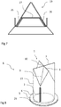
- FIG 1 shows a duckbill valve 19 with two duckbill reinforcements 20.
- the duckbill valve 19 has a duckbill valve wall 21 that extends from a valve base 5 to a valve functional area 6.
- FIG. The duckbill wall 21 is made of a thermoplastic elastomer.
- a permanent opening 29 is present in the valve base 5 .
- the valve functional area 6 has a beak valve slit 22 .
- the duckbill valve slit 22 opens to a port. In this condition, fluid can pass through the permanent opening into an interior volume of the duckbill valve 19 and out through the duckbill valve slit 22 formed passage flow out.
- the duckbill valve 19 should be designed so that it cannot roll up and evert in such a way that the duckbill valve slit 22 passes through the permanent opening when, in use, there is a pressure differential where a pressure in the environment exceeds a pressure in the interior volume of the duckbill valve 19 exceeds.
- the beak reinforcements 20 are glued onto an outside 23 of the beak valve wall 21 .
- the beak reinforcements 20 are made of polyamide. Due to their strength, they prevent the billet valve wall 21 from rolling up. This also effectively prevents the billet valve wall 21 from turning inside out.
- the beak reinforcements 20 are glued onto the beak valve wall 21 in such a way that they each run from one end of the beak valve slot 22 in the direction of the valve foot 5 . A small distance to the valve foot 5 is maintained.
- the beak valve reinforcements 20 are thus located in a region of the beak valve wall 21 which is not greatly deformed when the beak valve 19 is opened and closed.
- the area directly on the valve base 5 can act like an elastic joint.
- the duckbill valve reinforcements therefore impede the opening and closing of the duckbill valve 19 little or not at all.
- figure 2 shows a beak valve 19 with four beak reinforcements 20.
- the in figure 2 The duckbill valve 19 shown is similar to that in figure 1 shown beak valve 19.
- One difference is that the two beak reinforcements 20, which are adjacent to the ends of the beak valve slots 22, are not glued on, but consist of the same material as the beak valve wall 21 and the valve base 5 and together with the remaining parts of the beak valve 19 have been produced as an injection molded part.
- the material is also a thermoplastic elastomer or a silicone.
- the billet valve 19 has two further billet valve reinforcements 20 which each extend from a center of the billet valve slot 22 in the direction of the valve foot 5 .
- These beak valve reinforcements 20 do not extend all the way to the valve foot 5 either, but leave a gap so that the mobility of the beak valve wall 21 is not restricted.
- These duckbill valve reinforcements 20 also consist of thermoplastic elastomer or silicone and have also been produced together with the rest of the duckbill valve 19 as an injection molded part.
- FIG 3 shows a duckbill valve 19 with a duckbill reinforcement 20.
- the duckbill valve 19 corresponds to that in FIGS Figures 1 and 2 illustrated beak valves 19, but the beak valve reinforcement 20 is designed differently. Only one duckbill valve reinforcement 20 is present. This extends on an outer side 23 of the duckbill valve wall 21 from one end of the duckbill valve slot 22 in the direction of the valve base 5. There is also a small gap between the duckbill valve reinforcement 20 and the valve base 5.
- the billet valve reinforcement 20 becomes thinner towards the sides, transversely to its direction of extension, so that it merges smoothly into the billet valve wall 21 .
- figure 4 shows a beak valve 19 with two beak reinforcements 20.
- the in figure 4 The duckbill valve 19 shown is similar to that in figure 2 shown duckbill valve 19. However, there are only two duckbill valve reinforcements 20 available. These are provided on an inner side 24 of the duckbill valve wall 21 and extend from a center of the duckbill valve slot 22 towards the valve stem 5. There is also a small gap between the duckbill valve reinforcement 20 and the valve stem 5.
- the beak valve reinforcements 20 are designed to prevent the beak valve 19 from being everted without impeding the opening and closing of the beak valve 19 .
- figure 5 shows a beak valve 19 with four beak reinforcements 20. In figure 5 only three of the beak reinforcements 5 are visible. This in figure 5
- the duckbill valve 19 shown is similar to that in figure 4 However, there are two additional duckbill valve reinforcements 20 which extend from the ends of the duckbill valve slot 22 in the direction of the valve base 5. These are also provided on the inside 24 of the duckbill valve wall 21 . There is also a small gap between the beak valve reinforcement 20 and the valve foot 5 here.
- FIG. 6 shows a duckbill valve 19 with two support structures 26.
- the duckbill valve 19 is similar to that in FIGS Figures 1 to 5 shown beak valves 19, but the beak valve wall 21 is not provided with beak valve reinforcements 20.
- the duckbill valve 19 is attached to a valve carrier 25 which is provided with two support structures 26 .
- the two support structures 26 extend along the inside 24 of the billet valve wall 21 in the direction of the billet valve slot 22.
- FIG figure 7 shows a duckbill valve 19 with two support structures 26 and a passage dividing device 27.
- the duckbill valve 19 shown is similar to that in figure 6
- the beak valve 19 shown is the same.
- the same support structures 26 are present, but these are connected to one another by a passage dividing device 27 designed as a web 27 .
- the ridge 27 causes the passage through the duckbill valve 19 to be divided into two smaller passages. This places more restrictions on the size of the bodies that can pass through the valve.
- FIG 8 shows a cross slot valve 1 with a reinforcement area 2 close to the fold.
- the cross slot valve 1 has a cross slot valve wall 4 with a cylindrical shape, which merges into a valve base 5 at one end.
- a permanent opening 29 is provided in the valve base 5 .
- the cross-slit valve wall 4 merges into the valve functional area 6 with a first slit 7 and a second slit 8 arranged in the shape of a cross. in the in figure 8 shown state, the first slot 7 and the second slot 8 are closed.
- Four pleats 9 are provided, which run from a center point 10, in which the first slit 7 and the second slit 8 intersect, to the cross slit valve wall 4.
- the reinforcement region 2 close to the fold is arranged on an outer side 23 of the cross slot valve wall 4 .
- the reinforcement area 2 close to the fold extends between the end point of a fold 9 on the Phillips valve wall 4 and the valve foot 5 .
- the reinforcement area 2 close to the fold is at a distance from both the fold 9 and the valve foot 5 .
- the material from which the cross slot valve 1 with the reinforcement area 2 close to the folds was made is silicone.
- the cross slot valve 1 with the reinforcement area 2 close to the fold has been cast in one piece.
- the first slit 7 and the second slit 8 open to an orifice, so that a gas flows through the permanent orifice into the area within the Phillips valve wall 4 and can flow out of the opening in the valve functional area 6.
- the valve function area 6 deforms in the process.
- the area of the cross slot valve wall 4 in which the reinforcement area 2 near the folds is arranged deforms little or not at all when the valve function area 6 opens and closes.
- the reinforcement area 2 close to the fold is at a distance from the fold 9 and the valve base 5 because the cross-slit valve 1 deforms more directly on the fold 9 and on the valve base 5 during opening and closing. Therefore, the reinforcement area 2 close to the crease affects the opening and closing of the valve function area 6 little or not at all.
- valve function area 6 If there is a pressure difference where the pressure in the environment is higher than the pressure in the inner volume, it can happen that the valve function area 6 is pushed to the area inside the cross-slit valve wall 4 . If there were no reinforcement area 2 near the crease, the valve function area 6 could pass through the permanent opening, so that the cross-slit valve 1 would be everted. During this process, the cross slot valve 1 would roll over the cross slot valve wall 4 . At the in figure 8 shown embodiment, the reinforcement area 2 close to the fold prevents the cross slot valve 1 from rolling and thus from turning inside out.
- figure 9 shows a cross slit valve 1 with a reinforced area 3 close to the slit figure 9
- the cross slot valve 1 shown is similar to that in FIG figure 8 shown cross slot valve 1. The difference is that the reinforcement area 3 close to the slot is not adjacent to a fold 9 but to the second slot 8, with a distance to the slot also being maintained.
- Cross slot valve 1 shown has not been cast together with the rest of the cross slot valve 1, but has been glued to the cross slot valve wall 4. With the exception of the reinforcement area 3 near the slot, the cross slot valve 1 has been cast from silicone.
- the reinforcement area 3 close to the slit is made of polyamide.
- Reinforcement area 3 shown near the slit is located in an area of the cross slit valve 1 which deforms little or not at all when opening and closing. Opening and closing is therefore little or not affected at all. Since the reinforcing portion 3 close to the slit is adjacent to the second slit 8, tearing of the second slit 8 on this side can be limited.
- figure 10 shows a cross slit valve 1 with a reinforced area 2 near the folds and a reinforced area 3 near the slit.
- the cross slit valve 1 corresponds to FIG the in the figures 8 and 9 Phillips valves 1 shown.
- the reinforcement area 2 close to the folds corresponds to that in figure 8
- Reinforcement area 2 shown near the folds and reinforcement area 3 near the slit corresponds to that in FIG figure 9 Reinforcement area 3 near the slot shown.
- FIG 11 shows a joker valve 11 with three joker reinforcement areas 12 .
- the joker valve 11 has a valve base 5 with a permanent opening (not shown), a joker valve wall 17 and a valve function area 6 .
- the joker valve wall 17 encloses an inner volume that is delimited by the permanent opening and the valve functional area 6 .
- the valve function area 6 has three joker slots 13, 14 and 15, which extend from a joker center 16 to the outside. In the area of the joker slots 13, 14 and 15, the joker valve wall 17 forms a joker fold 28 so that two joker valve walls 17 lie on top of each other at each joker slot 13, 14 and 15 when the joker slots 13, 14 and 15 are closed .
- the three joker reinforcement areas 12 each run on the joker valve wall 17 from an area adjacent to one end of a joker slot 13, 14 and 15 in the direction of the valve foot 5. A distance from the valve foot 5 is maintained.
- the joker valve 11 is made of silicone.
- the joker reinforcement areas 12 comprise polystyrene.
- the Joker Valve 11 was manufactured using the multi-component injection molding process.
- the joker slots 13, 14 and 15 open to form a through-opening. Since the joker reinforcement areas 12 are located in an area of the joker valve wall 17 that deforms little or not at all when the joker valve 11 opens and closes, the opening and closing of the joker valve 11 is not impaired by the joker reinforcement areas 12 .
- the joker reinforcement areas 12 are suitable for preventing the joker valve 11 from rolling up and turning inside out.
- figure 12 shows a joker valve 11 with six reinforcement areas, of which 3 joker reinforcement areas 12 and 3 oval reinforcement areas 18.
- the in figure 12 Joker Valve 11 shown is similar to that in figure 11 shown joker valve 11. The difference is that in addition to the 3 joker reinforcement areas 12, the 3 oval reinforcement areas 18 are provided.
- the oval reinforcement areas 18 are provided on the outside of the joker valve wall 17 . They appear oval when viewed from above.
- the oval reinforcement areas 18 are made of polystyrene and the joker valve 11 has been manufactured using the multi-component injection molding process.
- the oval reinforcement areas 18 provide additional protection against rolling and eversion.
Description
- Die Erfindung betrifft ein Ventil für eine Inhaliervorrichtung.
- Ventile für Inhaliervorrichtungen sind im Stand der Technik bekannt und beispielsweise in
EP 2 008 678 A2 beschrieben.EP 2 008 678 A2 beschreibt ein einteiliges Zweiwegeventilsystem, das Inhalation und Exhalation mit einem einzigen Ventil ermöglicht. Das Ventil hat eine Basis, ein erstes Ventilelement, das in einer Ausführungsform eine Entenschnabelform hat, und ein zweites Ventilelement, das in einer Ausführungsform gestaltet ist wie eine drehbare Klappe. - Ventile für Inhaliervorrichtungen sollen im Gebrauch aus jedem Zustand heraus einen geöffneten und einen geschlossenen oder zumindest nahezu geschlossenen Zustand einnehmen können. Dazu sollten mögliche Verformungen des Ventils eingeschränkt sein. Dies führt zu Einschränkungen bei der Auswahl von geeigneten Geometrien und Werkstoffen für das Ventil.
- Verschiedene Ventile sind aus der
US 2004/0069360 A1 , derUS 2005/0187524 A1 , derUS 7 445 028 B1 , derUS 2011/108139 A1 und derEP 1 077 339 A2 bekannt. - Aufgabe der Erfindung ist es daher, ein Ventil bereitzustellen, das eine zuverlässige Ventilfunktion aufweist und bei dem trotzdem eine große Gestaltungsfreiheit im Hinblick auf Geometrien und Werkstoffe besteht.
- Die Aufgabe wird gelöst durch ein Ventil für eine Inhaliervorrichtung mit einem Innenvolumen, das zumindest teilweise von einer Ventilwand, einer permanenten Öffnung sowie einem Ventilfunktionsbereich begrenzt ist, wobei der Ventilfunktionsbereich eingerichtet ist, unterhalb einer Öffnungsdruckdifferenz zumindest nahezu geschlossen zu sein, und oberhalb einer Öffnungsdruckdifferenz geöffnet zu sein, so dass oberhalb der Öffnungsdruckdifferenz ein Fluid durch die permanente Öffnung in das Innenvolumen hinein und aus dem Ventilfunktionsbereich heraus strömen kann, wobei das Ventil einen Umstülpschutz aufweist, der eingerichtet ist, ein Umstülpen der Ventilwand zu erschweren oder zu verhindern.
- Das Ventil weist zweckmäßigerweise ein durchströmbares Innenvolumen auf und ist ein Schnabelventil.
- Das Schnabelventil ist vorzugsweise ein einteiliges gegossenes Ventil. Das Schnabelventil ist vorzugsweise eingerichtet, bei niedrigen Druckunterschieden zuverlässig einen Rückfluss zu verhindern. Zweckmäßigerweise weist ein Schnabelventil unterhalb einer Öffnungsdruckdifferenz einen Schlitz als Ventilfunktionsbereich auf, der eingerichtet ist, oberhalb einer Öffnungsdruckdifferenz eine Öffnung zu bilden. Zweckmäßigerweise ist ein Schlitz eine längliche Lücke. Der Schlitz ist vorzugsweise von zwei Bereichen der Ventilwand begrenzt, die im zumindest nahezu geschlossenen Zustand aufeinandertreffen ohne zu überlappen. Der Schlitz kann zwischen zwei Bereichen der Ventilwand vorgesehen sein, die im zumindest nahezu geschlossenen Zustand aufeinanderliegen oder nahe aneinander liegen. In einer bevorzugten Ausführungsform liegen im geschlossenen Zustand zwei Bereiche der Ventilwand mit den Innenseiten aneinander. Der Ventilfunktionsbereich ist zweckmäßigerweise eingerichtet, eine Öffnung zu bilden, indem sich die Bereiche der Ventilwand voneinander entfernen.
- Ein Kreuzschlitzventil, das vorliegend nicht beansprucht ist, weist als Ventilfunktionsbereich unterhalb einer Öffnungsdruckdifferenz zwei Schlitze auf, die zusammen eine Kreuzform bilden, und ebenfalls eingerichtet sind, oberhalb einer Öffnungsdruckdifferenz eine Öffnung zu bilden.
- Bei einem Joker Valve, das vorliegend nicht beansprucht ist, sind als Ventilfunktionsbereich unterhalb einer Offnungsdruckdifferenz drei Schlitze vorhanden, die sich in einem Punkt treffen, so dass von diesem Punkt aus drei Schlitze strahlenförmig nach außen weisen. Auch diese Schlitze sind eingerichtet, oberhalb der Öffnungsdruckdifferenz eine Öffnung zu bilden.
- Auch die Schlitze des Kreuzschlitzventils und des Joker Valves sind vorzugsweise von zwei Bereichen der Ventilwand begrenzt, die im zumindest nahezu geschlossenen Zustand stumpf aufeinandertreffenden. Die Schlitze können zwischen Bereichen der Ventilwand vorgesehen sein, die im zumindest nahezu geschlossenen Zustand aufeinanderliegen oder nahe aneinander liegen. In einer bevorzugten Ausführungsform liegen im geschlossenen Zustand Bereiche der Ventilwand mit den Innenseiten aneinander. Der Ventilfunktionsbereich ist zweckmäßigerweise eingerichtet, eine Öffnung zu bilden, indem sich die Bereiche der Ventilwände voneinander entfernen. Vorzugsweise umfasst die Inhaliervorrichtung eine Aerosolerzeugungsvorrichtung. Eine Aerosolerzeugungsvorrichtung weist bevorzugt einen Vernebler, einen Zerstäuber, einen Befeuchter, einen Druckluftvernebler, einen Luftzerstäuber, einen elektronischen Vernebler, einen Ultraschallvernebler, einen elektrohydrodynamischen Vernebler, einen elektrostatischen Vernebler, einen Membranvernebler, einen Vernebler mit einer vibrierenden Membran, einen elektronischen Vernebler mit einer vibrierenden Membran, einen Mesh-Vernebler, einen Düsenvernebler, einen Dosieraerosol-Inhalator (MDI), einen Pulver-Inhalator (DPI) oder eine Kombination davon auf. Der Dosieraerosol-Inhalator weist in einer Ausführungsform einen unter Druck stehenden Kanister mit einem Medikament und einem Treibgas auf. Zweckmäßigerweise ist der Kanister mit einem von Hand bedienbaren Aktuator verbunden. Es ist vorteilhaft, wenn der Dosieraerosol-Inhalator eingerichtet ist, bei der Aktivierung eine bestimmte Medikamentenmenge in Aerosolform abzugeben. In einer Ausführungsform ist die Aerosolerzeugungsvorrichtung für den Einsatz mit Beatmungsvorrichtungen eingerichtet.
- Es ist vorteilhaft, wenn die Inhaliervorrichtung eine Vorrichtung zur Bereitstellung von Aerosolen umfasst. Die Vorrichtung zur Bereitstellung von Aerosolen weist bevorzugt eine Inhalierhilfe, einen Spacer oder eine Chamber auf. Vorrichtungen zur Bereitstellung von Aerosolen sind vorzugsweise Vorrichtungen, die zur Verwendung mit Dosieraerosol-Inhalatoren (MDIs) vorgesehen sind. Sie stellen einen Speicherraum bereit, der dazu geeignet ist, Aerosol bevorzugt aus Dosieraerosol-Inhalatoren aufzunehmen, so dass es von Benutzern daraus abgeatmet werden kann. Spacer weisen keine Ein- und Ausatemventile auf, so dass ein Benutzer seine Atmung so koordinieren sollte, dass er nicht in den Spacer ausatmet. Chambers oder Holding Chambers weisen Aus- und bevorzugt auch Einatemventile auf. So kann erreicht werden, dass ein Ausatemstrom nicht in den Raum, in dem sich das Aerosol befindet, geleitet wird. Es kann erreicht werden, dass ein Medikament nur beim Einatmen aus dem Speicherraum heraus gelangen kann. Die Vorrichtung zur Bereitstellung von Aerosolen kann einen Speicherraum zur Aufnahme und Bereitstellung eines Aerosols, eine Düse zur Erzeugung des Aerosols und eine Halterung für einen Medikamentenkanister aufweisen. Dabei ist der Medikamentenkanister dazu vorgesehen, ein Medikament zur Aerosolerzeugung bereitzustellen.
- Aerosole sind Gemische aus festen oder flüssigen Schwebeteilchen und einem Gas.
- Aerosole sind bevorzugt zur Applikation auf oder in Teile des menschlichen oder tierischen Körpers, wie Haut, Körperhöhlen, Körperöffnungen, Nase, Nasennebenhöhlen, Kieferhöhle, Stirnhöhle, Keilbeinhöhle, Siebbeinzellen, Rachen, Kehlkopf, Luftröhre, Lunge, Stammbronchus, Bronchien, Bronchiolen, Lungenbläschen, Gelenke oder Bauchraum vorgesehen. Aerosole können eingesetzt werden, um Krankheiten von Menschen und Tieren zu diagnostizieren, vorzubeugen, zu therapieren oder um Menschen oder Tiere gegen Krankheiten zu immunisieren. Ein Innenvolumen ist ein Volumen, das zumindest teilweise von einem oder mehreren Bauteilen umschlossen ist. Das Innenvolumen kann eine Öffnung oder mehrere Öffnungen zur Umgebung aufweisen. Das Innenvolumen kann von einem Ventilfunktionsbereich begrenzt sein, der einen geöffneten und einen geschlossenen Zustand einnehmen kann.
- Eine Ventilwand weist vorzugsweise einen Kunststoff, besonders bevorzugt ein Elastomer, Silikon oder Gummi auf. Die Ventilwand grenzt zweckmäßigerweise ein Volumen von einer Umgebung ab. Vorzugsweise begrenzt die Ventilwand ein durchströmbares Volumen.
- Eine permanente Öffnung eines Ventils ist eine Öffnung, die im Betrieb des Ventils immer geöffnet ist. Es ist vorteilhaft, wenn die permanente Öffnung im Betrieb des Ventils immer die gleiche Größe hat.
- Ein Ventilfunktionsbereich ist ein Bereich eines Ventils, der sowohl zumindest nahezu geschlossen als auch geöffnet sein kann. Zweckmäßigerweise ist der Ventilfunktionsbereich eingerichtet, abhängig von der vorliegenden Druckdifferenz zwischen einer Umgebung und einem Innenvolumen zumindest nahezu geschlossen zu sein oder geöffnet zu sein. Es ist vorteilhaft, wenn der Ventilfunktionsbereich oberhalb einer Öffnungsdruckdifferenz geöffnet ist und unterhalb der Öffnungsdruckdifferenz geschlossen ist.
- Die Öffnungsdruckdifferenz ist eine vorgegebene Druckdifferenz, oberhalb derer ein Ventilfunktionsbereich geöffnet sein soll und unterhalb derer der Ventilfunktionsbereich geschlossen sein soll.
- Ein Fluid umfasst vorzugsweise ein Gas, eine Flüssigkeit oder ein Aerosol.
- Umstülpen ist ein Umwenden, derart, dass danach die Außenseite innen und die Innenseite außen ist. Bei einem Ventil kann ein Umstülpen derart ablaufen, dass eine Ventilwand sich von einem Ventilfunktionsbereich aus aufrollt, der Ventilfunktionsbereich durch die permanente Öffnung hindurch tritt und sich die Ventilwand wieder ausrollt. In diesem Zustand kann das Ventil nicht mehr wie vorgesehen öffnen und schließen.
- Ein Umstülpschutz ist eine Einrichtung, die geeignet ist, ein Umstülpen des Ventils zu behindern, zu begrenzen oder zu verhindern.
- Vorzugsweise umfasst der Umstülpschutz einen Verstärkungsbereich der Ventilwand. Dadurch kann der Umstülpschutz auf besonders einfache Weise bereitgestellt werden.
- In einer Ausführungsform ist als Verstärkungsbereich ein Fremdmaterial mit einem Zweikomponentenverfahren in das Ventil integriert worden. Vorzugsweise ist eine Hartkomponente in das Ventil ein- oder angespritzt worden.
- Der Verstärkungsbereich des Ventils kann auf einer Innenseite oder einer Außenseite des Ventils vorgesehen sein.
- Zweckmäßigerweise weist der Verstärkungsbereich eine Versteifung auf. Die Versteifung kann auf der abgeflachten oder planen Seite eines Schnabelventils vorgesehen sein. Es können Versteifungen im inneren Bereich des Ventils oder von außen vorgesehen sein.
- In einer Ausführungsform sind zylindrische Seitenteile eines Schnabelventils mit einem Verstärkungsbereich versehen.
- Eine besonders starke Versteifung lässt sich durch die Kombination von Versteifungen an zylindrischen Seitenteilen und abgeflachten Seiten eines Schnabelventils erreichen.
- Der Verstärkungsbereich der Ventilwand ist vorzugsweise ein langgestreckter Bereich, der eine größere Länge als Breite aufweist. Dabei erstreckt sich der Verstärkungsbereich von dem Ventilfunktionsbereich oder aus der Nähe des Ventilfunktionsbereichs in Richtung der permanenten Öffnung.
- Vorzugsweise ist der Verstärkungsbereich als verdickter Bereich ausgestaltet. Die Dicke des verdickten Bereichs entspricht vorzugsweise dem doppelten bis zwanzigfachen der Dicke der Ventilwand, besonders bevorzugt dem zwei- bis sechsfachen der Dicke der Ventilwand.
- Der verdickte Bereich ist vorzugsweise auf einer Innenseite der Ventilwand vorgesehen. In einer Ausführungsform ist der verdickte Bereich auf einer Außenseite der Ventilwand vorgesehen. Es kann vorteilhaft sein, den verdickten Bereich sowohl auf einer Innenseite als auch auf einer Außenseite der Ventilwand vorzusehen.
- In einer Ausführungsform ist der Verstärkungsbereich derart ausgestaltet, dass das Ventil seitlich versteift ist. Vorzugsweise ist das Ventil durch Profile versteift. Besonders bevorzugt sind die Profile direkt in das Material hinein konstruiert. Dadurch kann die Biegesteifigkeit besonders gut erhöht werden.
- Wenn der Verstärkungsbereich der Ventilwand von der permanenten Öffnung beabstandet ist, kann auf besonders einfache Weise erreicht werden, dass das Öffnen und Schließen des Ventils so ablaufen kann, dass es von dem Verstärkungsbereich der Ventilwand wenig oder gar nicht behindert ist. Das Ventil ist zweckmäßigerweise so ausgelegt, dass es sich beim Öffnen und Schließen vor allem in dem Bereich direkt an der permanenten Öffnung verformt. Der Bereich direkt an der permanenten Öffnung wirkt vorzugsweise als elastisches Gelenk.
- Es ist vorteilhaft, wenn der Verstärkungsbereich derart an der Ventilwand vorgesehen ist, dass der Drehpunkt der Seitenwände zur Öffnung des Ventils identisch bleibt. Zweckmäßigerweise wird der untere Bereich des Ventils freigehalten, um den Drehpunkt zu definieren. Dadurch kann erreicht werden, dass das Gelenk frei ist, das Ventil sich leicht öffnet und die Kraft, die zur Öffnung des Ventils erforderlich ist, sich nicht vergrößert.
- Der Abstand des Verstärkungsbereichs der Ventilwand von der permanenten Öffnung entspricht vorzugsweise mindestens der Dicke der Ventilwand. Dabei ist der Abstand des Verstärkungsbereichs der Ventilwand von der permanenten Öffnung zweckmäßigerweise maximal so groß, dass gerade noch Platz für den Verstärkungsbereich vorhanden ist. Besonders bevorzugt beträgt der Abstand des Verstärkungsbereichs der Ventilwand von der permanenten Öffnung das ein- bis fünffache der Dicke der Ventilwand.
- In einer Ausführungsform weist die Ventilwand einen Funktionswerkstoff auf und der Verstärkungsbereich der Ventilwand weist einen Stützwerkstoff auf. Dabei hat der Stützwerkstoff einen höheren E-Modul als der Funktionswerkstoff. Auf diese Weise lässt sich mit einem vergleichsweise geringen Materialvolumen eine hohe Stützwirkung erreichen. Es ist möglich, die Ventilwand bei einer relativ dünnen Ausgestaltung stark zu stützen.
- Das Ventil kann vollständig oder teilweise im Mehrkomponentenspritzgussverfahren, vorzugsweise im Zweikomponentenspritzgussverfahren hergestellt sein.
- Vorzugsweise hat der Verstärkungsbereich der Ventilwand mit dem Stützwerkstoff die gleiche Dicke wie die umgebende Ventilwand. So können Schmutzkanten auf einfache Weise vermieden werden. Wenn der Stützwerkstoff auf einer Außenseite der Ventilwand vorgesehen ist, kann der Stützwerkstoff auf besonders einfache Weise auf die Ventilwand aufgebracht werden. Durch eine Anordnung des Stützwerkstoffs auf einer Innenseite der Ventilwand kann eine besonders effektive Stützwirkung erreicht werden.
- Ein Funktionswerkstoff weist vorzugsweise einen E-Modul zwischen 0,003 und 5 kN/mm2, besonders bevorzugt zwischen 0,01 und 0,1 kN/mm2, auf. Ein Stützwerkstoff weist vorzugsweise einen E-Modul zwischen 1 und 500 kN/mm2, besonders bevorzugt zwischen 1 und 50 kN/mm2, auf.
- Der Funktionswerkstoff weist vorzugsweise ein Elastomer, besonders bevorzugt ein thermoplastisches Elastomer, Silikon oder Gummi auf. Der Stützwerkstoff weist vorzugsweise ein Polymer, besonders bevorzugt Polypropylen, Polyethylen, Polycarbonat, Polystyrol, Polyamid, Polyoxymethylen, einen thermoplastischen Kunststoff, einen verstärkten thermoplastischen Kunststoff, einen faserverstärkten thermoplastischen Kunststoff, Naturfasern oder Glasfasern auf.
- Wenn der Verstärkungsbereich der Ventilwand an den Ventilfunktionsbereich angrenzt, kann ein Aufrollen der Ventilwand vom Ventilfunktionsbereich aus auf besonders einfache Weise von Anfang an gestoppt werden. In einer bevorzugten Ausführungsform erstreckt sich der Verstärkungsbereich bis zu einem Schlitz des Ventilfunktionsbereichs.
- In einer Ausführungsform ist der Ventilfunktionsbereich eingerichtet, unterhalb einer Öffnungsdruckdifferenz einen Schlitz aufzuweisen und der Verstärkungsbereich der Ventilwand ist eingerichtet, unterhalb einer Öffnungsdruckdifferenz an ein Ende des Schlitzes anzugrenzen. So kann ein Einreißen des Schlitzes verhindert oder erschwert werden.
- In einer Ausführungsform erstreckt sich der Verstärkungsbereich vorzugsweise von dem Ende des Schlitzes oder aus der Nähe des Endes des Schlitzes auf der kürzesten Strecke oder nahezu auf der kürzesten Strecke in Richtung der permanenten Öffnung. Diese Ausführungsform ist besonders in Verbindung mit einem Schnabelventil zweckmäßig. In einigen Ausführungsformen des Ventils ist der Bereich zwischen dem Ende des Schlitzes und der permanenten Öffnung ein Bereich, der sich beim Öffnen und Schließen des Ventilfunktionsbereichs wenig oder gar nicht verformt. Durch das Vorsehen des Verstärkungsbereichs in diesem Bereich wird das Öffnen und Schließen daher wenig oder gar nicht behindert.
- Es ist vorteilhaft, wenn der Ventilfunktionsbereich eingerichtet ist, unterhalb einer Öffnungsdruckdifferenz einen Schlitz aufzuweisen und der Verstärkungsbereich der Ventilwand unterhalb einer Öffnungsdruckdifferenz an die Mitte des Schlitzes angrenzt. Der Verstärkungsbereich erstreckt sich vorzugsweise in Richtung der permanenten Öffnung. Insbesondere bei einem Schnabelventil erstreckt sich der Verstärkungsbereich vorzugsweise von einer Mitte des Schlitzes des Schnabelventils auf der kürzesten Strecke in Richtung der permanenten Öffnung.
- Dadurch ist es auf einfache Weise möglich, den Verstärkungsbereich an einer Stelle der Ventilwand vorzusehen, die beim Öffnen und Schließen des Ventilfunktionsbereichs wenig oder gar nicht verformt wird. Dadurch behindert der Verstärkungsbereich das Öffnen und Schließen des Ventilfunktionsbereichs nicht oder nur in sehr geringem Maße. Das Ventil kann daher leichter derart ausgelegt werden, dass es schon bei geringen Druckdifferenzen oder Unterdrücken öffnet.
- In einer Ausführungsform weist der Umstülpschutz ein Stützelement oder eine Ventilgeometrie für eine Ventilwand auf. Vorteilhafterweise weist das Stützelement einen Anlagebereich für eine Ventilwand auf. Der Anlagebereich ist zweckmäßigerweise dazu eingerichtet, dass sich ein Bereich der Ventilwand daran anlegen kann. Derart kann eine Bewegung der Ventilwand auf besonders einfache Weise begrenzt werden. Es ist besonders vorteilhaft, wenn der Anlagebereich eine Anlagefläche oder eine Anlagekante ist. So kann das Umstülpen auf besonders einfache Weise verhindert werden, ohne das Öffnen und Schließen zu behindern. Das Stützelement ist vorzugsweise mit einem Ventilträger verbunden, der dazu eingerichtet ist, das Ventil zu halten. Das Stützelement ist vorzugsweise in den Ventilträger integriert.
- Das Stützelement weist vorzugsweise einen Stützwerkstoff, zweckmäßigerweise eine Hartkomponente auf. Zweckmäßigerweise ist das Stützelement an einer Innenseite einer Ventilwand angeordnet. Das Stützelement ist vorzugsweise derart angeordnet, dass sich eine Ventilwand beim Öffnen des Ventilfunktionsbereichs an das Stützelement anlegt, wenn die Öffnung einen Durchlasszustand eingenommen hat, in dem ein vorgesehener Durchlass gebildet ist. Vorzugsweise ist keine weitere Bewegung des Ventilfunktionsbereichs in Richtung der permanenten Öffnung möglich, wenn die Ventilwand an dem Stützelement anliegt.
- In einer Ausführungsform ist das Stützelement zur abgeflachten Seite eines Schnabelventils hin ausgerichtet. Das Stützelement kann eine durchgängige Strebe aufweisen. In einer Ausführungsform weist das Stützelement die Form einer Antenne auf.
- Zweckmäßigerweise ist das Stützelement eingerichtet, unterhalb einer Öffnungsdruckdifferenz an einer Innenseite der Ventilwand anzuliegen. So kann ein Umstülpen besonders präzise begrenzt oder verhindert werden. Da das Stützelement an der Innenseite der Ventilwand anliegt muss sich die Ventilwand nicht zuerst verformen bis sie an dem Stützelement anliegt und der Umstülpprozess begrenzt oder gestoppt werden kann. Es ist daher auf einfache Weise möglich, den Umstülpprozess in einer frühen Phase zu stoppen.
- Es ist vorteilhaft, wenn der Umstülpschutz eine Durchlassunterteilungseinrichtung aufweist, die eingerichtet ist, einen Fluidstrom durch das Innenvolumen in mindestens zwei kleinere Fluidströme aufzuteilen. Größere Fremdkörper können ausgefiltert werden. So kann verhindert werden, dass größere Fremdkörper das Ventil passieren. Zweckmäßigerweise weist die Durchlassunterteilungseinrichtung einen Steg auf. In einer Ausführungsform weist die Durchlassunterteilungseinrichtung eine Lochplatte oder ein Netz auf.
- Im Folgenden werden die beigefügten Figuren genauer beschrieben.
-
Figur 1 zeigt ein Schnabelventil mit zwei Schnabelverstärkungen. -
Figur 2 zeigt ein Schnabelventil mit vier Schnabelverstärkungen. -
Figur 3 zeigt ein Schnabelventil mit einer Schnabelverstärkung. -
Figur 4 zeigt ein Schnabelventil mit zwei Schnabelverstärkungen. -
Figur 5 zeigt ein Schnabelventil mit vier Schnabelverstärkungen. -
Figur 6 zeigt ein Schnabelventil mit zwei Stützstrukturen. -
Figur 7 zeigt ein Schnabelventil mit zwei Stützstrukturen und einer Durchlassunterteilungseinrichtung. -
Figur 8 zeigt ein Kreuzschlitzventil mit einem faltennahen Verstärkungsbereich, das vorliegend nicht beansprucht ist. -
Figur 9 zeigt ein Kreuzschlitzventil mit einem schlitznahen Verstärkungsbereich, das vorliegend nicht beansprucht ist. -
Figur 10 zeigt ein Kreuzschlitzventil mit einem faltennahen und einem schlitznahen Verstärkungsbereich, das vorliegend nicht beansprucht ist. -
Figur 11 zeigt ein Joker Valve mit drei Joker Verstärkungsbereichen, das vorliegend nicht beansprucht ist. -
Figur 12 zeigt ein Joker Valve mit sechs Verstärkungsbereichen, das vorliegend nicht beansprucht ist. -
Figur 1 zeigt ein Schnabelventil 19 mit zwei Schnabelverstärkungen 20. Das Schnabelventil 19 weist eine Schnabelventilwand 21 auf, die sich von einem Ventilfuß 5 zu einem Ventilfunktionsbereich 6 erstreckt. Die Schnabelventilwand 21 ist aus einem thermoplastischen Elastomer hergestellt. In dem Ventilfuß 5 ist eine permanente Öffnung 29 vorhanden. Der Ventilfunktionsbereich 6 weist einen Schnabelventilschlitz 22 auf. Wenn der Druck in dem Innenvolumen den Druck in der Umgebung so übersteigt, dass eine Öffnungsdruckdifferenz vorliegt, öffnet sich der Schnabelventilschlitz 22 zu einer Durchlassöffnung. In diesem Zustand kann ein Fluid durch die permanente Öffnung in ein Innenvolumen des Schnabelventils 19 hinein und aus der durch den Schnabelventilschlitz 22 gebildeten Durchlassöffnung heraus strömen. - Das Schnabelventil 19 soll derart ausgeführt sein, dass es sich nicht derart aufrollen und umstülpen kann, dass der Schnabelventilschlitz 22 durch die permanente Öffnung hindurchtritt, wenn im Gebrauch eine Druckdifferenz vorliegt, bei der ein Druck in der Umgebung einen Druck in dem Innenvolumen des Schnabelventils 19 übersteigt.
- Um dies zu erreichen, sind zwei Schnabelverstärkungen 20 auf eine Außenseite 23 der Schnabelventilwand 21 aufgeklebt. Die Schnabelverstärkungen 20 sind aus Polyamid hergestellt. Durch ihre Festigkeit verhindern sie ein Aufrollen der Schnabelventilwand 21. Dadurch wird auch ein Umstülpen der Schnabelventilwand 21 wirksam verhindert.
- Die Schnabelverstärkungen 20 sind derart auf die Schnabelventilwand 21 aufgeklebt, dass sie jeweils von einem Ende des Schnabelventilschlitzes 22 in Richtung des Ventilfußes 5 verlaufen. Dabei wird ein kleiner Abstand zum Ventilfuß 5 eingehalten. Die Schnabelventilverstärkungen 20 befinden sich so in einem Bereich der Schnabelventilwand 21, der sich beim Öffnen und Schließen des Schnabelventils 19 nicht stark verformt. Der Bereich direkt am Ventilfuß 5 kann wie ein elastisches Gelenk wirken. Die Schnabelventilverstärkungen behindern das Öffnen und Schließen des Schnabelventils 19 daher wenig oder gar nicht.
-
Figur 2 zeigt ein Schnabelventil 19 mit vier Schnabelverstärkungen 20. Das inFigur 2 gezeigte Schnabelventil 19 ähnelt dem inFigur 1 gezeigten Schnabelventil 19. Ein Unterschied ist, dass die beiden Schnabelverstärkungen 20, die benachbart zu den Enden der Schnabelventilschlitze 22 sind, nicht aufgeklebt sind, sondern aus dem gleichen Material wie die Schnabelventilwand 21 und der Ventilfuß 5 bestehen und zusammen mit den übrigen Teilen des Schnabelventils 19 als Spritzgussteil hergestellt worden sind. Das Material ist ebenfalls ein thermoplastisches Elastomer oder ein Silikon. - Dadurch, dass die Wand durch die Schnabelverstärkungen 20 verdickt ist, erhält sie eine ausreichende Festigkeit, um sich nicht aufzurollen.
- Zusätzlich weist das Schnabelventil 19 noch zwei weitere Schnabelventilverstärkungen 20 auf, die sich jeweils von einer Mitte des Schnabelventilschlitzes 22 in Richtung des Ventilfußes 5 erstrecken. Auch diese Schnabelventilverstärkungen 20 erstrecken sich nicht ganz bis zu dem Ventilfuß 5 sondern lassen eine Lücke, damit die Beweglichkeit der Schnabelventilwand 21 nicht eingeschränkt wird. Diese Schnabelventilverstärkungen 20 bestehen ebenfalls aus thermoplastischem Elastomer oder aus Silikon und sind auch zusammen mit dem übrigen Schnabelventil 19 als Spritzgussteil hergestellt worden.
-
Figur 3 zeigt ein Schnabelventil 19 mit einer Schnabelverstärkung 20. Das Schnabelventil 19 entspricht den in denFiguren 1 und 2 dargestellten Schnabelventilen 19, jedoch ist die Schnabelventilverstärkung 20 anders ausgestaltet. Es ist nur eine Schnabelventilverstärkung 20 vorhanden. Diese erstreckt sich auf einer Außenseite 23 der Schnabelventilwand 21 von einem Ende des Schnabelventilschlitzes 22 in Richtung des Ventilfußes 5. Es ist ebenfalls eine kleine Lücke zwischen der Schnabelventilverstärkung 20 und dem Ventilfuß 5 vorhanden. Die Schnabelventilverstärkung 20 wird zu den Seiten hin, quer zu ihrer Erstreckungsrichtung, dünner, so dass sie fließend in die Schnabelventilwand 21 übergeht. -
Figur 4 zeigt ein Schnabelventil 19 mit zwei Schnabelverstärkungen 20. Das inFigur 4 gezeigte Schnabelventil 19 ähnelt dem inFigur 2 gezeigten Schnabelventil 19. Es sind jedoch nur zwei Schnabelventilverstärkungen 20 vorhanden. Diese sind auf einer Innenseite 24 der Schnabelventilwand 21 vorgesehen und erstrecken sich von einer Mitte des Schnabelventilschlitzes 22 in Richtung des Ventilfußes 5. Es ist ebenfalls eine kleine Lücke zwischen der Schnabelventilverstärkung 20 und dem Ventilfuß 5 vorhanden. - Auch bei dem in
Figur 4 gezeigten Schnabelventil 19 sind die Schnabelventilverstärkungen 20 eingerichtet, ein Umstülpen des Schnabelventils 19 zu verhindern, ohne das Öffnen und Schließen des Schnabelventils 19 zu behindern. -
Figur 5 zeigt ein Schnabelventil 19 mit vier Schnabelverstärkungen 20. InFigur 5 sind nur drei der Schnabelverstärkungen 5 sichtbar. Das inFigur 5 gezeigte Schnabelventil 19 ähnelt dem inFigur 4 gezeigten Schnabelventil 19. Es sind jedoch noch zwei zusätzliche Schnabelventilverstärkungen 20 vorhanden, die sich von den Enden des Schnabelventilschlitzes 22 in Richtung des Ventilfußes 5 erstrecken. Diese sind ebenfalls auf der Innenseite 24 der Schnabelventilwand 21 vorgesehen. Auch hier ist eine kleine Lücke zwischen der Schnabelventilverstärkung 20 und dem Ventilfuß 5 vorhanden. - Durch diese beiden zusätzlichen Schnabelventilverstärkungen 20 wird das Öffnen und Schließen des Schnabelventils 19 ebenfalls nicht behindert. Da vier Schnabelventilverstärkungen 20 vorhanden sind, können die einzelnen Schnabelventilverstärkungen 20 dünner oder flexibler ausgestaltet sein als bei dem in
Figur 4 gezeigten Schnabelventil und trotzdem die gleiche Wirkung gegen Aufrollen und Umstülpen entfalten. -
Figur 6 zeigt ein Schnabelventil 19 mit zwei Stützstrukturen 26. Das Schnabelventil 19 ähnelt den in denFiguren 1 bis 5 gezeigten Schnabelventilen 19, jedoch ist die Schnabelventilwand 21 nicht mit Schnabelventilverstärkungen 20 versehen. Das Schnabelventil 19 ist an einem Ventilträger 25 befestigt, der mit zwei Stützstrukturen 26 versehen ist. Die beiden Stützstrukturen 26 erstrecken sich an der Innenseite 24 der Schnabelventilwand 21 entlang in Richtung des Schnabelventilschlitzes 22. - Dadurch, dass die Stützstrukturen 26 nicht mit der Schnabelventilwand 21 verbunden sind, beeinträchtigen sie das Öffnen und Schließen des Ventilfunktionsbereichs 6 nicht.
- Ein Aufrollen und Umstülpen der Schnabelventilwand 21 wird jedoch wirksam verhindert, da die Stützstrukturen 26 eine Anlagekante für eine Schnabelventilwand 21 und eine ausreichende Festigkeit aufweisen, um ein Aufrollen der Schnabelventilwand 21 zu begrenzen.
-
Figur 7 zeigt ein Schnabelventil 19 mit zwei Stützstrukturen 26 und einer Durchlassunterteilungseinrichtung 27. Das inFigur 7 gezeigte Schnabelventil 19 ähnelt dem inFigur 6 gezeigten Schnabelventil 19. Es sind die gleichen Stützstrukturen 26 vorhanden, jedoch sind diese durch eine als Steg 27 ausgebildete Durchlassunterteilungseinrichtung 27 miteinander verbunden. - Der Steg 27 bewirkt, dass der Durchlass durch das Schnabelventil 19 in zwei kleinere Durchlässe unterteilt ist. Dadurch ist die Größe der Körper, die das Ventil passieren können, stärker eingeschränkt.
-
Figur 8 zeigt ein Kreuzschlitzventil 1 mit einem faltennahen Verstärkungsbereich 2. Das Kreuzschlitzventil 1 weist eine Kreuzschlitzventilwand 4 mit einer zylindrischen Form auf, die an einem Ende in einen Ventilfuß 5 übergeht. In dem Ventilfuß 5 ist eine permanente Öffnung 29 vorgesehen. An dem anderen Ende der zylindrischen Form geht die Kreuzschlitzventilwand 4 in den Ventilfunktionsbereich 6 mit einem ersten Schlitz 7 und einem zweiten Schlitz 8, die kreuzförmig angeordnet sind, über. In dem inFigur 8 gezeigten Zustand sind der erste Schlitz 7 und der zweite Schlitz 8 geschlossen. Es sind vier Falten 9 vorgesehen, die von einem Mittelpunkt 10, in dem der erste Schlitz 7 und der zweite Schlitz 8 sich kreuzen, zu der Kreuzschlitzventilwand 4 verlaufen. Innerhalb der Kreuzschlitzventilwand 4 zwischen der permanenten Öffnung und dem Ventilfunktionsbereich 6 befindet sich ein Innenvolumen. Auf einer Außenseite 23 der Kreuzschlitzventilwand 4 ist der faltennahe Verstärkungsbereich 2 angeordnet. Der faltennahe Verstärkungsbereich 2 erstreckt sich zwischen dem Endpunkt einer Falte 9 auf der Kreuzschlitzventilwand 4 und dem Ventilfuß 5. Dabei ist der faltennahe Verstärkungsbereich 2 sowohl von der Falte 9 als auch von dem Ventilfuß 5 beabstandet. Der Werkstoff, aus dem das Kreuzschlitzventil 1 mit dem faltennahen Verstärkungsbereich 2 hergestellt worden ist, ist Silikon. Das Kreuzschlitzventil 1 mit dem faltennahen Verstärkungsbereich 2 ist einstückig gegossen worden. - Wenn der Druck in dem Innenvolumen den Druck in der Umgebung übersteigt und die Druckdifferenz zwischen Innenvolumen und Umgebung einen festgelegten Grenzwert übersteigt, öffnen sich der erste Schlitz 7 und der zweite Schlitz 8 zu einer Öffnung, so dass ein Gas durch die permanente Öffnung in den Bereich innerhalb der Kreuzschlitzventilwand 4 hinein und aus der Öffnung in dem Ventilfunktionsbereich 6 heraus strömen kann. Dabei verformt sich der Ventilfunktionsbereich 6. Der Bereich der Kreuzschlitzventilwand 4, in dem der faltennahe Verstärkungsbereich 2 angeordnet ist, verformt sich beim Öffnen und Schließen des Ventilfunktionsbereichs 6 wenig oder gar nicht. Der faltennahe Verstärkungsbereich 2 ist von der Falte 9 und dem Ventilfuß 5 beabstandet, weil sich das Kreuzschlitzventil 1 direkt an der Falte 9 und an dem Ventilfuß 5 beim Öffnen und Schließen stärker verformt. Daher beeinträchtigt der faltennahe Verstärkungsbereich 2 das Öffnen und Schließen des Ventilfunktionsbereichs 6 wenig oder gar nicht.
- Wenn eine Druckdifferenz vorliegt, bei der der Druck in der Umgebung höher ist als der Druck in dem Innenvolumen, kann es passieren, dass der Ventilfunktionsbereich 6 zu dem Bereich innerhalb der Kreuzschlitzventilwand 4 gedrückt wird. Wenn kein faltennaher Verstärkungsbereich 2 vorhanden wäre, könnte der Ventilfunktionsbereich 6 durch die permanente Öffnung hindurch gelangen, so dass das Kreuzschlitzventil 1 umgestülpt wäre. Bei diesem Vorgang würde das Kreuzschlitzventil 1 über die Kreuzschlitzventilwand 4 abrollen. Bei der in
Figur 8 gezeigten Ausführungsform verhindert der faltennahe Verstärkungsbereich 2 das Abrollen und damit das Umstülpen des Kreuzschlitzventils 1. -
Figur 9 zeigt ein Kreuzschlitzventil 1 mit einem schlitznahen Verstärkungsbereich 3. Das inFigur 9 gezeigte Kreuzschlitzventil 1 ähnelt dem inFigur 8 gezeigten Kreuzschlitzventil 1. Der Unterschied liegt darin, dass der schlitznahe Verstärkungsbereich 3 nicht an eine Falte 9 sondern an den zweiten Schlitz 8 angrenzt, wobei ebenfalls ein Abstand zu dem Schlitz eingehalten ist. Außerdem ist der schlitznahe Verstärkungsbereich 3 bei dem inFigur 9 gezeigten Kreuzschlitzventil 1 nicht zusammen mit dem übrigen Kreuzschlitzventil 1 gegossen worden, sondern auf die Kreuzschlitzventilwand 4 aufgeklebt worden. Das Kreuzschlitzventil 1 ist mit Ausnahme des schlitznahen Verstärkungsbereichs 3 aus Silikon gegossen worden. Der schlitznahe Verstärkungsbereich 3 ist aus Polyamid hergestellt. - Auch der in
Figur 9 gezeigte schlitznahe Verstärkungsbereich 3 befindet sich in einem Bereich des Kreuzschlitzventils 1, der sich beim Öffnen und Schließen wenig oder gar nicht verformt. Das Öffnen und Schließen wird daher wenig oder gar nicht beeinträchtigt. Da der schlitznahe Verstärkungsbereich 3 an den zweiten Schlitz 8 angrenzt, kann ein Ausreißen des zweiten Schlitzes 8 an dieser Seite begrenzt werden. - Wenn eine Druckdifferenz vorliegt, bei der der Druck in der Umgebung höher ist als der Druck in dem Innenvolumen, verhindert der in
Figur 9 gezeigte schlitznahe Verstärkungsbereich 3 entsprechend dem inFigur 8 gezeigten faltennahen Verstärkungsbereich 2 ein Aufrollen und Umstülpen des Kreuzschlitzventils 1. Der unerwünschte Aufrollprozess wird etwas früher gestoppt als bei dem inFigur 8 gezeigten Kreuzschlitzventil, da der schlitznahe Verstärkungsbereich 3 sich näher an dem Bereich des Funktionsbereichs 5 befindet, der abhängig von der anliegenden Druckdifferenz eine Öffnung aufweist. -
Figur 10 zeigt ein Kreuzschlitzventil 1 mit einem faltennahen Verstärkungsbereich 2 und einem schlitznahen Verstärkungsbereich 3. Das Kreuzschlitzventil 1 entspricht den in denFiguren 8 und9 gezeigten Kreuzschlitzventilen 1. Der faltennahe Verstärkungsbereich 2 entspricht dem inFigur 8 gezeigten faltennahen Verstärkungsbereich 2 und der schlitznahe Verstärkungsbereich 3 entspricht dem inFigur 9 gezeigten schlitznahen Verstärkungsbereich 3. - Durch die Kombination des faltennahen Verstärkungsbereichs 2 mit dem schlitznahen Verstärkungsbereich 3 wird ein noch besserer Schutz gegen Aufrollen und Umstülpen des Kreuzschlitzventils 1 erzielt.
-
Figur 11 zeigt ein Joker Valve 11 mit drei Joker Verstärkungsbereichen 12. Das Joker Valve 11 weist einen Ventilfuß 5 mit einer nicht gezeigten permanenten Öffnung, eine Joker Ventilwand 17 und einen Ventilfunktionsbereich 6 auf. Die Joker Ventilwand 17 umschließt ein Innenvolumen, das von der permanenten Öffnung und dem Ventilfunktionsbereich 6 begrenzt wird. Der Ventilfunktionsbereich 6 weist drei Joker Schlitze 13, 14 und 15 auf, die sich von einem Joker Mittelpunkt 16 nach außen erstrecken. Im Bereich der Joker Schlitze 13, 14 und 15 bildet die Joker Ventilwand 17 jeweils eine Joker Falte 28, so dass an jedem Joker Schlitz 13, 14 und 15 zwei Joker Ventilwände 17 aufeinander liegen, wenn die Joker Schlitze 13, 14 und 15 geschlossen sind. - Die drei Joker Verstärkungsbereiche 12 verlaufen auf der Joker Ventilwand 17 jeweils von einem Bereich, der einem Ende eines Joker Schlitzes 13, 14 und 15 benachbart ist, in Richtung des Ventilfußes 5. Dabei wird ein Abstand zum Ventilfuß 5 eingehalten. Das Joker Valve 11 ist mit Ausnahme der Joker Verstärkungsbereiche 12 aus Silikon hergestellt. Die Joker Verstärkungsbereiche 12 weisen Polystyrol auf. Das Joker Valve 11 ist im Mehrkomponentenspritzgussverfahren hergestellt worden.
- Wenn der Druck im Innenvolumen so ansteigt, dass ein vorgegebener Differenzdruck zwischen dem Innenvolumen und der Umgebung überschritten wird, öffnen sich die Joker Schlitze 13, 14 und 15 zu einer Durchlassöffnung. Da sich die Joker Verstärkungsbereiche 12 in einem Bereich der Joker Ventilwand 17 befinden, der sich beim Öffnen und Schließen des Joker Valves 11 wenig oder gar nicht verformt, wird das Öffnen und Schließen des Joker Valves 11 durch die Joker Verstärkungsbereiche 12 nicht beeinträchtigt.
- Wenn der Druck in der Umgebung den Druck im Innenvolumen übersteigt, wird der Ventilfunktionsbereich 6 in Richtung der permanenten Öffnung gedrückt. Die Joker Verstärkungsbereiche 12 sind geeignet, ein Aufrollen und Umstülpen des Joker Valves 11 zu verhindern.
-
Figur 12 zeigt ein Joker Valve 11 mit sechs Verstärkungsbereichen, davon 3 Joker Verstärkungsbereiche 12 und 3 Ovalverstärkungsbereiche 18. Das inFigur 12 gezeigte Joker Valve 11 ähnelt dem inFigur 11 gezeigten Joker Valve 11. Der Unterschied ist, dass zusätzlich zu den 3 Joker Verstärkungsbereichen 12 die 3 Ovalverstärkungsbereiche 18 vorgesehen sind. Die Ovalverstärkungsbereiche 18 sind außen an der Joker Ventilwand 17 vorgesehen. In der Draufsicht erscheinen sie oval. Die Ovalverstärkungsbereiche 18 sind aus Polystyrol hergestellt und das Joker Valve 11 ist im Mehrkomponentenspritzgussverfahren hergestellt worden. - Die Ovalverstärkungsbereiche 18 bieten einen zusätzlichen Schutz gegen Aufrollen und Umstülpen.
-
- 1
- Kreuzschlitzventil
- 2
- faltennaher Verstärkungsbereich
- 3
- schlitznaher Verstärkungsbereich
- 4
- Kreuzschlitzventilwand
- 5
- Ventilfuß
- 6
- Ventilfunktionsbereich
- 7
- erster Schlitz
- 8
- zweiter Schlitz
- 9
- Falte
- 10
- Mittelpunkt
- 11
- Joker Valve
- 12
- Joker Verstärkungsbereiche
- 13, 14, 15
- Joker Schlitz
- 16
- Joker Mittelpunkt
- 17
- Joker Ventilwand
- 18
- Ovalverstärkungsbereich
- 19
- Schnabelventil
- 20
- Schnabelverstärkung
- 21
- Schnabelventilwand
- 22
- Schnabelventilschlitz
- 23
- Außenseite
- 24
- Innenseite
- 25
- Ventilträger
- 26
- Stützstruktur
- 27
- Steg
- 28
- Joker Falte
- 29
- Permanente Öffnung
Claims (12)
- Ventil (1, 11, 19) für eine Inhaliervorrichtung mit einem Innenvolumen, das zumindest teilweise von einer Ventilwand (4, 17, 21), einer permanenten Öffnung (29) sowie einem Ventilfunktionsbereich (6) begrenzt ist,
wobei der Ventilfunktionsbereich (6) eingerichtet ist, unterhalb einer Öffnungsdruckdifferenz zumindest nahezu geschlossen zu sein, und oberhalb einer Öffnungsdruckdifferenz geöffnet zu sein, so dass oberhalb der Öffnungsdruckdifferenz ein Fluid durch die permanente Öffnung (29) in das Innenvolumen hinein und aus dem Ventilfunktionsbereich (6) heraus strömen kann,
dadurch gekennzeichnet, dass das Ventil einen Umstülpschutz aufweist, der eingerichtet ist, ein Umstülpen der Ventilwand (4, 17, 21) zu erschweren oder zu verhindern, und das Ventil ein Schnabelventil ist. - Ventil (1, 11, 19) nach Anspruch 1, dadurch gekennzeichnet, dass der Umstülpschutz einen Verstärkungsbereich (2, 3, 12, 18, 20) der Ventilwand (4, 17, 21) umfasst.
- Ventil (1, 11, 19) nach Anspruch 2, dadurch gekennzeichnet, dass der Verstärkungsbereich (2, 3, 12, 18, 20) der Ventilwand (4, 17, 21) von der permanenten Öffnung (29) beabstandet ist.
- Ventil (1, 11, 19) nach Anspruch 2 oder Anspruch 3, dadurch gekennzeichnet, dass die Ventilwand (4, 17, 21) einen Funktionswerkstoff aufweist und der Verstärkungsbereich (2, 3, 12, 18, 20) der Ventilwand (4, 17, 21) einen Stützwerkstoff aufweist, der einen höheren E-Modul hat als der Funktionswerkstoff.
- Ventil (1, 11, 19) nach einem der Ansprüche 2 bis 4, dadurch gekennzeichnet, dass der Verstärkungsbereich (2, 3, 12, 18, 20) der Ventilwand (4, 17, 21) an den Ventilfunktionsbereich (6) angrenzt.
- Ventil (1, 11, 19) nach Anspruch 5, dadurch gekennzeichnet, dass der Ventilfunktionsbereich (6) eingerichtet ist, unterhalb einer Öffnungsdruckdifferenz einen Schlitz (7, 8, 13, 14, 15, 22) aufzuweisen und der Verstärkungsbereich (2, 3, 12, 18, 20) der Ventilwand (4, 17, 21) an ein Ende des Schlitzes (7, 8, 13, 14, 15, 22) angrenzt.
- Ventil (1, 11, 19) nach einem der vorhergehenden Ansprüche, dadurch gekennzeichnet, dass der Ventilfunktionsbereich (6) eingerichtet ist, unterhalb einer Öffnungsdruckdifferenz einen Schlitz (7, 8, 13, 14, 15, 22) aufzuweisen und der Verstärkungsbereich (2, 3, 12, 18, 20) der Ventilwand (4, 17, 21) unterhalb einer Öffnungsdruckdifferenz an die Mitte des Schlitzes (7, 8, 13, 14, 15, 22) angrenzt.
- Ventil (1, 11, 19) nach Anspruch 1, dadurch gekennzeichnet, dass der Umstülpschutz ein Stützelement (26) für eine Ventilwand (4, 17, 21) aufweist.
- Ventil (1, 11, 19) nach Anspruch 8, dadurch gekennzeichnet, dass das Stützelement (26) eingerichtet ist, unterhalb einer Öffnungsdruckdifferenz an einer Innenseite (24) der Ventilwand (4, 17, 21) anzuliegen.
- Ventil (1, 11, 19) nach Anspruch 8 oder Anspruch 9, dadurch gekennzeichnet, dass der Umstülpschutz (26) eine Durchlassunterteilungseinrichtung (27) aufweist, die eingerichtet ist, einen Fluidstrom durch das Innenvolumen in mindestens zwei kleinere Fluidströme aufzuteilen.
- Verwendung des Ventils nach einem der vorhergehenden Ansprüche in einer Inhaliervorrichtung.
- Inhaliervorrichtung mit einem Ventil nach einem der vorhergehenden Ansprüche 1 bis 10.
Priority Applications (2)
| Application Number | Priority Date | Filing Date | Title |
|---|---|---|---|
| EP16158227.5A EP3213789B2 (de) | 2016-03-02 | 2016-03-02 | Ventil |
| US15/444,395 US10335561B2 (en) | 2016-03-02 | 2017-02-28 | Valve |
Applications Claiming Priority (1)
| Application Number | Priority Date | Filing Date | Title |
|---|---|---|---|
| EP16158227.5A EP3213789B2 (de) | 2016-03-02 | 2016-03-02 | Ventil |
Publications (3)
| Publication Number | Publication Date |
|---|---|
| EP3213789A1 EP3213789A1 (de) | 2017-09-06 |
| EP3213789B1 EP3213789B1 (de) | 2018-08-01 |
| EP3213789B2 true EP3213789B2 (de) | 2022-01-12 |
Family
ID=55451109
Family Applications (1)
| Application Number | Title | Priority Date | Filing Date |
|---|---|---|---|
| EP16158227.5A Active EP3213789B2 (de) | 2016-03-02 | 2016-03-02 | Ventil |
Country Status (2)
| Country | Link |
|---|---|
| US (1) | US10335561B2 (de) |
| EP (1) | EP3213789B2 (de) |
Families Citing this family (8)
| Publication number | Priority date | Publication date | Assignee | Title |
|---|---|---|---|---|
| JP2019500196A (ja) * | 2015-12-21 | 2019-01-10 | スリーエム イノベイティブ プロパティズ カンパニー | 医療用吸入器で使用するための流れ調整器 |
| JP2020535375A (ja) * | 2017-09-27 | 2020-12-03 | ジョンソン コントロールズ テクノロジー カンパニーJohnson Controls Technology Company | 筐体を通気するためのシステム及び方法 |
| WO2019236662A1 (en) | 2018-06-05 | 2019-12-12 | Teleflex Medical Incorporated | Valved spacer for inhalation device |
| US11073214B2 (en) * | 2019-03-29 | 2021-07-27 | Rapak, Llc | Duckbill valve and method for making a duckbill valve |
| BR112022001231A2 (pt) * | 2019-07-24 | 2022-04-05 | Quest Medical Inc | Válvula de ventilação de descarga de vácuo filtrado |
| EP3818971A1 (de) * | 2019-11-07 | 2021-05-12 | Koninklijke Philips N.V. | Luftnachfüllventil für einen trinkbecher oder eine saugflasche |
| USD1010101S1 (en) | 2020-09-18 | 2024-01-02 | Trudell Medical International | Holding chamber |
| CA3228997A1 (en) * | 2021-08-20 | 2023-02-23 | Sebastien Deubel | Valve assembly |
Citations (2)
| Publication number | Priority date | Publication date | Assignee | Title |
|---|---|---|---|---|
| US3504699A (en) † | 1967-03-20 | 1970-04-07 | Grimar Inc | Check valve |
| EP2014325A1 (de) † | 2007-06-06 | 2009-01-14 | Markos Mefar S.P.A. | Einwegmembranventil für ein Aerosolinhalationssystem zur Zuführung des Aerosols zur Lunge |
Family Cites Families (8)
| Publication number | Priority date | Publication date | Assignee | Title |
|---|---|---|---|---|
| US4148420A (en) * | 1978-01-30 | 1979-04-10 | Scale Models Unlimited | Self-sealing caps for squeeze-type containers |
| US6585005B1 (en) * | 1999-08-18 | 2003-07-01 | Red Valve Co., Inc. | Reinforced tide gate valve |
| US20050187524A1 (en) * | 2000-12-19 | 2005-08-25 | Willis Allan F. | Sealing valve assembly for medical products |
| US20030205226A1 (en) | 2002-05-02 | 2003-11-06 | Pre Holding, Inc. | Aerosol medication inhalation system |
| US6904908B2 (en) | 2002-05-21 | 2005-06-14 | Trudell Medical International | Visual indicator for an aerosol medication delivery apparatus and system |
| US6953059B2 (en) * | 2002-07-29 | 2005-10-11 | Red Valve Company, Inc. | Check valve with hanger |
| US7445028B1 (en) * | 2005-09-26 | 2008-11-04 | General Rubber Corporation | Check valves |
| US8276616B2 (en) * | 2009-03-20 | 2012-10-02 | Xylem Ip Holdings Llc | High pressure duckbill valve and insert |
-
2016
- 2016-03-02 EP EP16158227.5A patent/EP3213789B2/de active Active
-
2017
- 2017-02-28 US US15/444,395 patent/US10335561B2/en active Active
Patent Citations (2)
| Publication number | Priority date | Publication date | Assignee | Title |
|---|---|---|---|---|
| US3504699A (en) † | 1967-03-20 | 1970-04-07 | Grimar Inc | Check valve |
| EP2014325A1 (de) † | 2007-06-06 | 2009-01-14 | Markos Mefar S.P.A. | Einwegmembranventil für ein Aerosolinhalationssystem zur Zuführung des Aerosols zur Lunge |
Also Published As
| Publication number | Publication date |
|---|---|
| US10335561B2 (en) | 2019-07-02 |
| EP3213789A1 (de) | 2017-09-06 |
| EP3213789B1 (de) | 2018-08-01 |
| US20170252524A1 (en) | 2017-09-07 |
Similar Documents
| Publication | Publication Date | Title |
|---|---|---|
| EP3213789B2 (de) | Ventil | |
| EP0895788B1 (de) | Inhalationstherapiegerät mit einem Ventil zur Begrenzung des Inspirationsflusses | |
| EP1620155B1 (de) | Vernebleranschlussvorrichtung für beatmungsgeräte oder dergleichen | |
| DE102010048317B4 (de) | Künstliche Nase mit Sprechventil | |
| DE60030964T2 (de) | Vorrichtung zur applikation von medikamenten in form eines aerosols | |
| DE102005041717B4 (de) | Atemmaske mit Strömungsleitstrukturen | |
| DE10126807A1 (de) | Inhalationstherapiegerät mit einem Ventil zur Begrenzung des Inspirationsflusses | |
| DE102017004928A1 (de) | Auslassvorrichtung | |
| DE19801545A1 (de) | Mundstück für Inhalationstherapiegeräte | |
| DE102014005646A1 (de) | Pulverinhalator und Pulverinhalationsset | |
| DE19912461B4 (de) | Vorrichtung zur Flußbegrenzung bei niedrigen Differenzdrücken | |
| EP3107493B1 (de) | Sprechventil mit zumindest teilweise aus einem elastischen material gebildeten deckelteil | |
| WO2015067332A1 (de) | Nasendusche mit durch atemluft beaufschlagbarem ventil | |
| DE202020102748U1 (de) | Atemschutzmaske mit Trinkhalmöffnung | |
| WO2004076156A1 (de) | Verbundbauteil mit teilbeweglichen elementen und verfahren zu dessen herstellung | |
| EP2805748B1 (de) | Atemmaske mit Notatemventil | |
| EP1656844A1 (de) | Atemschutzmaske | |
| EP2427241B1 (de) | Filtervorrichtung zur verwendung bei einem tracheostoma | |
| EP3624883A1 (de) | Exspirationsventil für eine beatmungsvorrichtung mit geräuschminderndem strömungswiderstand | |
| DE102015201124A1 (de) | Sauerstoffmaske | |
| EP3528882A1 (de) | Exspirationsventil für eine beatmungsvorrichtung mit geräuschemissionsreduzierter ventilgestaltung | |
| DE102015204645B4 (de) | Atemschutzmaske | |
| WO2015124277A1 (de) | Sprechventil mit deckelteil, umfassend ein kolbenförmiges verschlussteil | |
| EP4021543A1 (de) | Anschlussbauteil für eine trachealkanüle, insbesondere zum schutz vor unbeabsichtigtem verschliessen derselben | |
| EP3478349B1 (de) | Vorrichtung zur ausgabe einer durch luft austragbaren substanz |
Legal Events
| Date | Code | Title | Description |
|---|---|---|---|
| PUAI | Public reference made under article 153(3) epc to a published international application that has entered the european phase |
Free format text: ORIGINAL CODE: 0009012 |
|
| STAA | Information on the status of an ep patent application or granted ep patent |
Free format text: STATUS: THE APPLICATION HAS BEEN PUBLISHED |
|
| AK | Designated contracting states |
Kind code of ref document: A1 Designated state(s): AL AT BE BG CH CY CZ DE DK EE ES FI FR GB GR HR HU IE IS IT LI LT LU LV MC MK MT NL NO PL PT RO RS SE SI SK SM TR |
|
| AX | Request for extension of the european patent |
Extension state: BA ME |
|
| STAA | Information on the status of an ep patent application or granted ep patent |
Free format text: STATUS: REQUEST FOR EXAMINATION WAS MADE |
|
| 17P | Request for examination filed |
Effective date: 20170926 |
|
| RBV | Designated contracting states (corrected) |
Designated state(s): AL AT BE BG CH CY CZ DE DK EE ES FI FR GB GR HR HU IE IS IT LI LT LU LV MC MK MT NL NO PL PT RO RS SE SI SK SM TR |
|
| STAA | Information on the status of an ep patent application or granted ep patent |
Free format text: STATUS: EXAMINATION IS IN PROGRESS |
|
| 17Q | First examination report despatched |
Effective date: 20180118 |
|
| GRAP | Despatch of communication of intention to grant a patent |
Free format text: ORIGINAL CODE: EPIDOSNIGR1 |
|
| STAA | Information on the status of an ep patent application or granted ep patent |
Free format text: STATUS: GRANT OF PATENT IS INTENDED |
|
| INTG | Intention to grant announced |
Effective date: 20180511 |
|
| GRAS | Grant fee paid |
Free format text: ORIGINAL CODE: EPIDOSNIGR3 |
|
| GRAA | (expected) grant |
Free format text: ORIGINAL CODE: 0009210 |
|
| STAA | Information on the status of an ep patent application or granted ep patent |
Free format text: STATUS: THE PATENT HAS BEEN GRANTED |
|
| AK | Designated contracting states |
Kind code of ref document: B1 Designated state(s): AL AT BE BG CH CY CZ DE DK EE ES FI FR GB GR HR HU IE IS IT LI LT LU LV MC MK MT NL NO PL PT RO RS SE SI SK SM TR |
|
| REG | Reference to a national code |
Ref country code: GB Ref legal event code: FG4D Free format text: NOT ENGLISH |
|
| REG | Reference to a national code |
Ref country code: CH Ref legal event code: EP Ref country code: AT Ref legal event code: REF Ref document number: 1023591 Country of ref document: AT Kind code of ref document: T Effective date: 20180815 |
|
| REG | Reference to a national code |
Ref country code: IE Ref legal event code: FG4D Free format text: LANGUAGE OF EP DOCUMENT: GERMAN |
|
| REG | Reference to a national code |
Ref country code: DE Ref legal event code: R096 Ref document number: 502016001550 Country of ref document: DE |
|
| REG | Reference to a national code |
Ref country code: NL Ref legal event code: FP |
|
| REG | Reference to a national code |
Ref country code: LT Ref legal event code: MG4D |
|
| PG25 | Lapsed in a contracting state [announced via postgrant information from national office to epo] |
Ref country code: BG Free format text: LAPSE BECAUSE OF FAILURE TO SUBMIT A TRANSLATION OF THE DESCRIPTION OR TO PAY THE FEE WITHIN THE PRESCRIBED TIME-LIMIT Effective date: 20181101 Ref country code: SE Free format text: LAPSE BECAUSE OF FAILURE TO SUBMIT A TRANSLATION OF THE DESCRIPTION OR TO PAY THE FEE WITHIN THE PRESCRIBED TIME-LIMIT Effective date: 20180801 Ref country code: RS Free format text: LAPSE BECAUSE OF FAILURE TO SUBMIT A TRANSLATION OF THE DESCRIPTION OR TO PAY THE FEE WITHIN THE PRESCRIBED TIME-LIMIT Effective date: 20180801 Ref country code: GR Free format text: LAPSE BECAUSE OF FAILURE TO SUBMIT A TRANSLATION OF THE DESCRIPTION OR TO PAY THE FEE WITHIN THE PRESCRIBED TIME-LIMIT Effective date: 20181102 Ref country code: IS Free format text: LAPSE BECAUSE OF FAILURE TO SUBMIT A TRANSLATION OF THE DESCRIPTION OR TO PAY THE FEE WITHIN THE PRESCRIBED TIME-LIMIT Effective date: 20181201 Ref country code: NO Free format text: LAPSE BECAUSE OF FAILURE TO SUBMIT A TRANSLATION OF THE DESCRIPTION OR TO PAY THE FEE WITHIN THE PRESCRIBED TIME-LIMIT Effective date: 20181101 Ref country code: FI Free format text: LAPSE BECAUSE OF FAILURE TO SUBMIT A TRANSLATION OF THE DESCRIPTION OR TO PAY THE FEE WITHIN THE PRESCRIBED TIME-LIMIT Effective date: 20180801 Ref country code: LT Free format text: LAPSE BECAUSE OF FAILURE TO SUBMIT A TRANSLATION OF THE DESCRIPTION OR TO PAY THE FEE WITHIN THE PRESCRIBED TIME-LIMIT Effective date: 20180801 Ref country code: PL Free format text: LAPSE BECAUSE OF FAILURE TO SUBMIT A TRANSLATION OF THE DESCRIPTION OR TO PAY THE FEE WITHIN THE PRESCRIBED TIME-LIMIT Effective date: 20180801 |
|
| PG25 | Lapsed in a contracting state [announced via postgrant information from national office to epo] |
Ref country code: AL Free format text: LAPSE BECAUSE OF FAILURE TO SUBMIT A TRANSLATION OF THE DESCRIPTION OR TO PAY THE FEE WITHIN THE PRESCRIBED TIME-LIMIT Effective date: 20180801 Ref country code: LV Free format text: LAPSE BECAUSE OF FAILURE TO SUBMIT A TRANSLATION OF THE DESCRIPTION OR TO PAY THE FEE WITHIN THE PRESCRIBED TIME-LIMIT Effective date: 20180801 Ref country code: HR Free format text: LAPSE BECAUSE OF FAILURE TO SUBMIT A TRANSLATION OF THE DESCRIPTION OR TO PAY THE FEE WITHIN THE PRESCRIBED TIME-LIMIT Effective date: 20180801 |
|
| REG | Reference to a national code |
Ref country code: DE Ref legal event code: R026 Ref document number: 502016001550 Country of ref document: DE |
|
| PLBI | Opposition filed |
Free format text: ORIGINAL CODE: 0009260 |
|
| PG25 | Lapsed in a contracting state [announced via postgrant information from national office to epo] |
Ref country code: ES Free format text: LAPSE BECAUSE OF FAILURE TO SUBMIT A TRANSLATION OF THE DESCRIPTION OR TO PAY THE FEE WITHIN THE PRESCRIBED TIME-LIMIT Effective date: 20180801 Ref country code: RO Free format text: LAPSE BECAUSE OF FAILURE TO SUBMIT A TRANSLATION OF THE DESCRIPTION OR TO PAY THE FEE WITHIN THE PRESCRIBED TIME-LIMIT Effective date: 20180801 Ref country code: CZ Free format text: LAPSE BECAUSE OF FAILURE TO SUBMIT A TRANSLATION OF THE DESCRIPTION OR TO PAY THE FEE WITHIN THE PRESCRIBED TIME-LIMIT Effective date: 20180801 Ref country code: IT Free format text: LAPSE BECAUSE OF FAILURE TO SUBMIT A TRANSLATION OF THE DESCRIPTION OR TO PAY THE FEE WITHIN THE PRESCRIBED TIME-LIMIT Effective date: 20180801 Ref country code: EE Free format text: LAPSE BECAUSE OF FAILURE TO SUBMIT A TRANSLATION OF THE DESCRIPTION OR TO PAY THE FEE WITHIN THE PRESCRIBED TIME-LIMIT Effective date: 20180801 |
|
| PLAX | Notice of opposition and request to file observation + time limit sent |
Free format text: ORIGINAL CODE: EPIDOSNOBS2 |
|
| 26 | Opposition filed |
Opponent name: L'AIR LIQUIDE, SOCIETE ANONYME POUR L'ETUDE ET L'E Effective date: 20190411 |
|
| PG25 | Lapsed in a contracting state [announced via postgrant information from national office to epo] |
Ref country code: SK Free format text: LAPSE BECAUSE OF FAILURE TO SUBMIT A TRANSLATION OF THE DESCRIPTION OR TO PAY THE FEE WITHIN THE PRESCRIBED TIME-LIMIT Effective date: 20180801 Ref country code: DK Free format text: LAPSE BECAUSE OF FAILURE TO SUBMIT A TRANSLATION OF THE DESCRIPTION OR TO PAY THE FEE WITHIN THE PRESCRIBED TIME-LIMIT Effective date: 20180801 Ref country code: SM Free format text: LAPSE BECAUSE OF FAILURE TO SUBMIT A TRANSLATION OF THE DESCRIPTION OR TO PAY THE FEE WITHIN THE PRESCRIBED TIME-LIMIT Effective date: 20180801 |
|
| PG25 | Lapsed in a contracting state [announced via postgrant information from national office to epo] |
Ref country code: SI Free format text: LAPSE BECAUSE OF FAILURE TO SUBMIT A TRANSLATION OF THE DESCRIPTION OR TO PAY THE FEE WITHIN THE PRESCRIBED TIME-LIMIT Effective date: 20180801 |
|
| PLBB | Reply of patent proprietor to notice(s) of opposition received |
Free format text: ORIGINAL CODE: EPIDOSNOBS3 |
|
| PG25 | Lapsed in a contracting state [announced via postgrant information from national office to epo] |
Ref country code: MC Free format text: LAPSE BECAUSE OF FAILURE TO SUBMIT A TRANSLATION OF THE DESCRIPTION OR TO PAY THE FEE WITHIN THE PRESCRIBED TIME-LIMIT Effective date: 20180801 |
|
| REG | Reference to a national code |
Ref country code: CH Ref legal event code: PL |
|
| PG25 | Lapsed in a contracting state [announced via postgrant information from national office to epo] |
Ref country code: LU Free format text: LAPSE BECAUSE OF NON-PAYMENT OF DUE FEES Effective date: 20190302 |
|
| REG | Reference to a national code |
Ref country code: BE Ref legal event code: MM Effective date: 20190331 |
|
| PG25 | Lapsed in a contracting state [announced via postgrant information from national office to epo] |
Ref country code: IE Free format text: LAPSE BECAUSE OF NON-PAYMENT OF DUE FEES Effective date: 20190302 Ref country code: CH Free format text: LAPSE BECAUSE OF NON-PAYMENT OF DUE FEES Effective date: 20190331 Ref country code: LI Free format text: LAPSE BECAUSE OF NON-PAYMENT OF DUE FEES Effective date: 20190331 |
|
| PG25 | Lapsed in a contracting state [announced via postgrant information from national office to epo] |
Ref country code: FR Free format text: LAPSE BECAUSE OF NON-PAYMENT OF DUE FEES Effective date: 20190331 Ref country code: BE Free format text: LAPSE BECAUSE OF NON-PAYMENT OF DUE FEES Effective date: 20190331 |
|
| PG25 | Lapsed in a contracting state [announced via postgrant information from national office to epo] |
Ref country code: TR Free format text: LAPSE BECAUSE OF FAILURE TO SUBMIT A TRANSLATION OF THE DESCRIPTION OR TO PAY THE FEE WITHIN THE PRESCRIBED TIME-LIMIT Effective date: 20180801 |
|
| PG25 | Lapsed in a contracting state [announced via postgrant information from national office to epo] |
Ref country code: PT Free format text: LAPSE BECAUSE OF FAILURE TO SUBMIT A TRANSLATION OF THE DESCRIPTION OR TO PAY THE FEE WITHIN THE PRESCRIBED TIME-LIMIT Effective date: 20181201 Ref country code: MT Free format text: LAPSE BECAUSE OF FAILURE TO SUBMIT A TRANSLATION OF THE DESCRIPTION OR TO PAY THE FEE WITHIN THE PRESCRIBED TIME-LIMIT Effective date: 20180801 |
|
| PLAB | Opposition data, opponent's data or that of the opponent's representative modified |
Free format text: ORIGINAL CODE: 0009299OPPO |
|
| R26 | Opposition filed (corrected) |
Opponent name: L'AIR LIQUIDE, SOCIETE ANONYME POUR L'ETUDE ET L'EXPLOITATION DES PROCEDES GEORGES CLAUDE Effective date: 20190411 |
|
| PG25 | Lapsed in a contracting state [announced via postgrant information from national office to epo] |
Ref country code: CY Free format text: LAPSE BECAUSE OF FAILURE TO SUBMIT A TRANSLATION OF THE DESCRIPTION OR TO PAY THE FEE WITHIN THE PRESCRIBED TIME-LIMIT Effective date: 20180801 |
|
| PG25 | Lapsed in a contracting state [announced via postgrant information from national office to epo] |
Ref country code: HU Free format text: LAPSE BECAUSE OF FAILURE TO SUBMIT A TRANSLATION OF THE DESCRIPTION OR TO PAY THE FEE WITHIN THE PRESCRIBED TIME-LIMIT; INVALID AB INITIO Effective date: 20160302 |
|
| APAH | Appeal reference modified |
Free format text: ORIGINAL CODE: EPIDOSCREFNO |
|
| APBM | Appeal reference recorded |
Free format text: ORIGINAL CODE: EPIDOSNREFNO |
|
| APBP | Date of receipt of notice of appeal recorded |
Free format text: ORIGINAL CODE: EPIDOSNNOA2O |
|
| APBU | Appeal procedure closed |
Free format text: ORIGINAL CODE: EPIDOSNNOA9O |
|
| PUAH | Patent maintained in amended form |
Free format text: ORIGINAL CODE: 0009272 |
|
| STAA | Information on the status of an ep patent application or granted ep patent |
Free format text: STATUS: PATENT MAINTAINED AS AMENDED |
|
| 27A | Patent maintained in amended form |
Effective date: 20220112 |
|
| AK | Designated contracting states |
Kind code of ref document: B2 Designated state(s): AL AT BE BG CH CY CZ DE DK EE ES FI FR GB GR HR HU IE IS IT LI LT LU LV MC MK MT NL NO PL PT RO RS SE SI SK SM TR |
|
| REG | Reference to a national code |
Ref country code: DE Ref legal event code: R102 Ref document number: 502016001550 Country of ref document: DE |
|
| REG | Reference to a national code |
Ref country code: NL Ref legal event code: FP |
|
| REG | Reference to a national code |
Ref country code: AT Ref legal event code: MM01 Ref document number: 1023591 Country of ref document: AT Kind code of ref document: T Effective date: 20210302 |
|
| PG25 | Lapsed in a contracting state [announced via postgrant information from national office to epo] |
Ref country code: MK Free format text: LAPSE BECAUSE OF FAILURE TO SUBMIT A TRANSLATION OF THE DESCRIPTION OR TO PAY THE FEE WITHIN THE PRESCRIBED TIME-LIMIT Effective date: 20180801 |
|
| PG25 | Lapsed in a contracting state [announced via postgrant information from national office to epo] |
Ref country code: AT Free format text: LAPSE BECAUSE OF NON-PAYMENT OF DUE FEES Effective date: 20210302 |
|
| PGFP | Annual fee paid to national office [announced via postgrant information from national office to epo] |
Ref country code: GB Payment date: 20230323 Year of fee payment: 8 Ref country code: DE Payment date: 20230320 Year of fee payment: 8 |
|
| PGFP | Annual fee paid to national office [announced via postgrant information from national office to epo] |
Ref country code: NL Payment date: 20230322 Year of fee payment: 8 |
|
| P01 | Opt-out of the competence of the unified patent court (upc) registered |
Effective date: 20230525 |
|
| PGFP | Annual fee paid to national office [announced via postgrant information from national office to epo] |
Ref country code: NL Payment date: 20240320 Year of fee payment: 9 |