EP3213338B1 - Röntgenstrahlungserzeuger - Google Patents
Röntgenstrahlungserzeuger Download PDFInfo
- Publication number
- EP3213338B1 EP3213338B1 EP15825793.1A EP15825793A EP3213338B1 EP 3213338 B1 EP3213338 B1 EP 3213338B1 EP 15825793 A EP15825793 A EP 15825793A EP 3213338 B1 EP3213338 B1 EP 3213338B1
- Authority
- EP
- European Patent Office
- Prior art keywords
- base body
- heat
- heat dissipating
- ray tube
- elements
- Prior art date
- Legal status (The legal status is an assumption and is not a legal conclusion. Google has not performed a legal analysis and makes no representation as to the accuracy of the status listed.)
- Active
Links
Images


Classifications
-
- H—ELECTRICITY
- H01—ELECTRIC ELEMENTS
- H01J—ELECTRIC DISCHARGE TUBES OR DISCHARGE LAMPS
- H01J35/00—X-ray tubes
- H01J35/02—Details
- H01J35/04—Electrodes ; Mutual position thereof; Constructional adaptations therefor
- H01J35/08—Anodes; Anti cathodes
- H01J35/12—Cooling non-rotary anodes
-
- H—ELECTRICITY
- H01—ELECTRIC ELEMENTS
- H01J—ELECTRIC DISCHARGE TUBES OR DISCHARGE LAMPS
- H01J2235/00—X-ray tubes
- H01J2235/12—Cooling
- H01J2235/1225—Cooling characterised by method
- H01J2235/1262—Circulating fluids
- H01J2235/1283—Circulating fluids in conjunction with extended surfaces (e.g. fins or ridges)
-
- H—ELECTRICITY
- H01—ELECTRIC ELEMENTS
- H01J—ELECTRIC DISCHARGE TUBES OR DISCHARGE LAMPS
- H01J2235/00—X-ray tubes
- H01J2235/12—Cooling
- H01J2235/1225—Cooling characterised by method
- H01J2235/1291—Thermal conductivity
- H01J2235/1295—Contact between conducting bodies
Definitions
- the present invention relates generally to an X-ray tube with an anode which, during operation, carries a high voltage, preferably more than 120 kV, particularly preferably more than 300 kV, and which heats up.
- the invention relates to an X-ray tube with a heat sink which is suitable for cooling the high-voltage anode when space is limited.
- X-ray tubes as an example of a device for generating X-rays (X-ray generator) are known.
- X-ray generator X-ray generator
- DD 139 327 A suggests, for example, that to increase the dielectric strength in a housing of an X-ray tube, a sleeve made of a dielectric material such as epoxy resin with quartz powder, ceramic or PTFE, which essentially accommodates a glass bulb of the X-ray tube inserted therein and covers the X-ray tube radially opposite a housing, is proposed . Due to the additional dielectric material, the anode of the tube is better electrically shielded or insulated from the environment.
- DE 10 2008 006 620 A1 shows an X-ray tube in which the tubular housing of the tube is made of a ceramic. The assemblies for generating the X-rays are arranged in the housing. The anode of an X-ray tube heats up during operation; to avoid damage from overheating, the heat from the anode is usually dissipated via a heat sink.
- Passive heat sinks enlarge the heat-emitting surface of a heat-producing component and are generally known; for example from the DE 20 2007 007 568 U1 .
- Known heat sinks usually consist of a metal with good thermal conductivity, for example aluminum or copper.
- a metal heat sink on the part of the anode located outside the housing of the X-ray tube there is a minimum distance between the heat sink and other components or housing parts that have a reference potential (e.g. ground, GND, etc.) must be observed in order to prevent voltage flashovers. If the X-ray tube is to be operated with higher voltages, this safety distance must be increased accordingly. This can require an enlargement of the outer housing of a system in which the X-ray tube is arranged.
- An insulation sleeve, as with the DD 139 327 A would affect the heat dissipation.
- a heat sink made of a ceramic with good thermal conductivity properties such as aluminum oxide or aluminum nitride, could be used.
- a ceramic heat sink is expensive to manufacture because special shapes must be used.
- the metal of the anode - usually copper - has a higher coefficient of thermal expansion than the ceramic heat sink attached to the outside. This makes the heat transfer between the anode and the heat sink problematic: On the one hand, the heat sink should be in the best possible thermal conduction contact with the anode in order to achieve the highest possible heat transfer coefficient. On the other hand, the heat sink must not be damaged or even blown off by the anode that expands when it is heated.
- the design requirement is "as compact as possible”.
- the size of an X-ray generator is limited by the fact that certain components have to be integrated and the distances between the components, which are at different electrical potentials, have to be chosen so that the dielectric strength of the insulation media is not exceeded at any point.
- JP 2009 164038 A shows as the closest prior art an X-ray tube with an anode heat sink according to the preamble of claim 1. A similar arrangement is shown in FIG WO 2013/021794 A1 .
- US 2003/221816 A1 shows a heat sink with a metallic base body and ceramic plate-shaped heat dissipation elements. Similar arrangements are shown in CN 202 221 659 U , pin-shaped heat emitting elements are also shown there.
- WO 2012/031943 A1 shows, inter alia, cylindrical heat sinks in which a metallic base body is cast onto ceramic plate-shaped heat dissipation elements.
- a core idea of the invention is to use a base body of a heat sink as an interface to the anode to be cooled, which is preferably made of metal, made of a metal that conducts heat well, such as. B. aluminum (Al) or copper (Cu), and on the base body to increase the surface area as heat transfer to the environment heat dissipation elements such. B. cooling pins and / or cooling fins made of a heat conductive, but electrically insulating ceramic, such. B. aluminum nitride (AIN) or silicon carbide (SiC) to be arranged.
- AIN aluminum nitride
- SiC silicon carbide
- This special structure of the heat sink can advantageously meet three requirements: (i) the component to which the heat sink is attached can be cooled by thermal radiation and, above all, convection; (ii) The insulation distance is compared to neighboring components that have different electrical potentials - in comparison z. B. with a conventional all-metal or all-metal heat sink - increased; and (iii) stress problems that would result from different coefficients of thermal expansion between the component to be cooled and the ceramic can be compensated for by the base body as a transition piece.
- the combination of inexpensive components and the additional function of electrical insulation makes the heat sink according to the invention superior to known heat sinks made of aluminum or ceramic.
- the base body can consist of a metal with good thermal conductivity properties.
- the base body preferably consists of a metal or a metal alloy with a coefficient of thermal conductivity of at least 100 W / (m K), preferably more than 200 W / (m K).
- aluminum (Al), copper (Cu), silver (Ag) or an alloy of these metals are suitable as metal.
- the material of the electrically insulating heat dissipation elements preferably has a coefficient of thermal conductivity of more than 100 W / (m K). Electrically insulating here means that the material has a specific resistance of at least 10 12 ⁇ * m / mm 2 and more.
- the heat dissipating elements are preferably made of a ceramic. For example, silicon carbide (SiC) or aluminum nitride (AlN) are suitable as ceramic.
- Suitable combinations with regard to the choice of material for the base body and the heat dissipating elements are, for example, copper / silicon carbide or aluminum / aluminum nitride.
- the heat dissipation elements are plate-shaped. That is to say, the heat-emitting elements have the shape of plates.
- the base body has a corresponding receptacle or recess for each heat dissipation element.
- the respective receptacle or recess is dimensioned in accordance with the shape of a connecting section of a heat dissipating element to be inserted.
- the heat dissipating elements, d. H. the connecting sections are non-positively connected to the base body.
- the respective connecting section is fastened in the associated receptacle by means of a press fit or clamping.
- the base body can be heated.
- the press connection is formed, as it were, by shrinking the base body onto the connecting section of the heat dissipating element. Since ceramics can absorb compressive forces very well, this connection complies with the strength properties of ceramics.
- the main body of the heat sink can basically be a CNC-manufactured metal part.
- the base body of the cooling body for the anode can be tubular, in particular cylindrical. If the base body is essentially a cylinder, it can be manufactured as a rotating body.
- the heat absorption surface is formed by an inner surface of a recess running axially in the base body. The shape of the recess is adapted for coupling with the anode as a heat source.
- the remaining surface of the base body is again part of the heat release surface in which the receptacles for the heat release elements are formed. In each of these receptacles, a heat-emitting element is preferably inserted and fastened in a manner that conducts heat well.
- the recesses are designed as axially extending slots or grooves in the outer surface of the base body.
- the plate-shaped ceramic elements are inserted into these recesses as heat dissipation elements in a form-fitting and force-fitting manner.
- the X-ray tube with the heat sink according to the invention is an electrical device which has a component which carries a high voltage during operation and which heats up, the heat sink being connected to this component in a thermally conductive manner.
- the X-ray tube has the anode as a component that carries a high voltage and warms up during operation.
- a heat sink is connected to the anode in a thermally conductive manner.
- the heat dissipation elements preferably have a height starting from the base body of the cooling body. In the X-ray tube according to the invention, the height is dimensioned such that, taking into account the high voltage and possibly an insulation medium surrounding the heat dissipating elements, a predetermined sufficient dielectric strength with respect to the surroundings is achieved or ensured.
- the size of the X-ray tube is limited by the fact that certain components have to be integrated and the distances between the components, which are at different electrical potentials, have to be selected so that the dielectric strength of the insulation medium arranged in between is not exceeded.
- the component to be cooled is essentially the anode of the X-ray tube.
- the main body of the heat sink serves particularly advantageously as a transition piece between the Operation of the heating anode (as a heat-generating component) and the ceramic heat-dissipating elements, which act as cooling fins.
- the base body of the cooling body can be manufactured particularly easily as a rotating body.
- slots or grooves can be machined into the base body by means of a CNC machine.
- the slots or grooves are matched to the dimensions of the connecting sections of the heat dissipating elements in accordance with the joining technique selected.
- Ceramic plates are particularly suitable as heat dissipation elements, since they are available as inexpensive mass-produced items.
- the Figures 1a to 3b show three examples of heat sinks 1, 2 and 3, each with a base body 10.1, 10.2, 10.3 made of metal.
- the base body each has a heat absorption surface 12.1, 12.2, 12.3 for coupling to a heat source.
- the heat source can be a component that is heated or warmed up during operation. During operation, heat is conducted in a known manner by conduction into the base body of the heat sink. In other words, the heat absorption area essentially corresponds to the contact area with the heat source.
- the base body 10.1, 10.2, 10.3 can use its outer surfaces, which are not in contact with the heat source, as a heat release surface to transfer the heat to an insulating medium surrounding the heat release surfaces (usually a fluid, such as, for example, in the simplest case the ambient air) by conduction, Emit heat radiation and convection.
- the part of the outer surface of the base body 10.1, 10.2, 10.3 which is opposite the heat absorption surface 12.1, 12.2, 12.3 essentially forms the heat release surface 14.1, 14.2, 14.3 of the base body 10.1, 10.2, 10.3.
- heat emission elements 16.1, 16.2, 16.3 are arranged on the base body 10.1, 10.2, 10.3 in the area of the heat emission surface 14.1, 14.2, 14.3 and are connected to the base body 10.1, 10.2, 10.3 in a heat-conducting manner.
- the heat release surface 14.1, 14.2, 14.3 of the base body 10.1, 10.2, 10.3 is increased by the surfaces of the heat release elements 16.1, 16.2, 16.3.
- the heat dissipation elements 16.1, 16.2, 16.3 are made of an electrically insulating material, which preferably has a thermal conductivity in the order of magnitude of the metal Has base body 10.1, 10.2, 10.3.
- the heat dissipation elements 16.1, 16.2, 16.3 are inserted into correspondingly shaped receptacles 18.1, 18.2, 18.3, which are formed in the base body 10.1, 10.2, 10.3, with respective connecting sections 20.1, 20.2, 20.3 in the base body 10.1, 10.2, 10.3 in a heat-conducting manner.
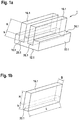
- Figure 1a shows the first example of the heat sink 1 with plate-shaped heat dissipation elements 16.1.
- Figure 1b shows one of the heat dissipation elements 16.1 of FIG Figure 1a in isolation.
- the heat dissipation element 16.1 has the shape of a plate, ie it is plate-shaped.
- Plate-shaped means that the heat dissipating element 16.1 has substantially larger dimensions in length and height compared to the width.
- the plate-shaped heat dissipation element 16.1 has a width B and a height which is composed of a height h of the connecting section 20.1 and the rest of this protruding section with the length H after insertion into the base body 10.1.
- the longitudinal extension of the heat dissipation element 16.1 is marked with L. Since B ⁇ L and B ⁇ (h + H), the heat emitting element is plate-shaped.
- the heat dissipation element 16.1 is inserted into the base body 10.1 in the recesses 18.1 appropriately machined or formed there and fastened in it in a thermally conductive manner using one of the measures to be discussed further below.
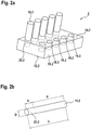
- FIG 2a shows the second example of the heat sink 2.
- the heat dissipation elements 16.2 are made of an electrically insulating material, pins or rods which again have a thermal conductivity in the order of magnitude of the metal of the base body 10.2. Similar to the Figure 1a the pin-shaped or rod-shaped heat dissipation elements 16.2 with a respective connecting section 20.2 are inserted into correspondingly machined or shaped recesses 18.2 in the base body 10.2 and fastened there with good thermal conductivity.
- the heat dissipation element 16.2 is essentially cylindrical and has a length L and a diameter D.
- the length L is made up of the connecting section 20.2, which is similar to FIG Figure 1a or 1b has the length h, which corresponds to the depth of one of the receptacles 18.2 in the base body 10 corresponds to.
- the remaining part of the pin-shaped heat dissipation element 16.2 has the length H, which protrudes from the base body 10.2 when the heat dissipation element 16.2 is inserted into the base body 10.2; that is, L is here (h + H).
- Figure 3a shows the third example of the heat sink 3.
- receptacles 18.3 are formed in the heat dissipation surface 14.3 of the base body 10.3 (as in the first and second exemplary embodiments), into which the tubular heat dissipation elements 16.3 are inserted and fastened.
- the tubular heat dissipation elements 16.3 again consist of an electrically insulating material which has a thermal conductivity in the order of magnitude of the metal of the base body 10.3.
- the tubular heat dissipation elements 16.3 have the shape of a hollow cylinder with an outside diameter D and an inside diameter d as well as a length L.
- the length of the heat dissipation element 16.3 is again divided into the connecting section 20.3 with a length h, which is inserted into the correspondingly designed receptacles 18.3 of the Base body 10.3 are inserted with a depth h.
- the remaining section of the heat dissipation element 16.3, which protrudes from the base body 10.3 when the heat dissipation element 16.3 is inserted into the base body 10.3, has the length H; ie, here is L - similar to in the Figures 2a, 2b - equal (h + H).
- the base body 10.1, 10.2, 10.3 made of a highly thermally conductive metal, preferably with a coefficient of thermal conductivity of 100 W / (m K) or more.
- a highly thermally conductive metal preferably with a coefficient of thermal conductivity of 100 W / (m K) or more.
- aluminum with a coefficient of thermal conductivity of approx. 240 W / (m K) or copper with a coefficient of thermal conductivity of approx. 400 W / (m K) was used.
- the base body 10.1, 10.2, 10.3 can also consist of another metal or a metal alloy.
- the heat dissipation elements 16.1, 16.2 and 16.3 are made of a ceramic which has a coefficient of thermal conductivity that is of the same order of magnitude as that of the metal of the base body 10.1, 10.2, 10.3.
- the ceramic thus preferably also has a coefficient of thermal conductivity of more than 100 W / (m K).
- aluminum nitride with a coefficient of thermal conductivity of approx. 180 to 220 W / (mK) or silicon carbide with a coefficient of thermal conductivity of approx. 350 W / (mK) was used.
- the heat dissipation elements 16.1, 16.2 and 16.3 are each inserted into corresponding receptacles 18.1, 18.2 and 18.3 which are incorporated into the base body 10.1, 10.2, 10.3.
- various joining techniques can be used.
- the respective heat dissipation element 16.1 or 16.2 can be positively and / or non-positively connected to the base body 10.1, 10.2 in that the respective use section 20.1, 20.2 is fastened in the associated receptacle 18.1, 18.2 by means of a press fit or clamping.
- the base body 10.1, 10.2 can be heated accordingly, for example, so that the base body 10.1, 10.2 expands.
- the ceramic heat dissipation elements 16.1, 16.2 can be inserted into the respective receptacles 18.1, 18.2.
- the heat dissipation elements 16.1, 16.2 are firmly connected to the base body 10.1, 10.2. It is only necessary to ensure that the dimensions of the recesses 18.1, 18.2 are dimensioned so that the heat dissipation elements 16.1, 16.2 cannot loosen at the temperatures reached during normal operation due to the expansion of the metal of the base body 10.1, 10.2.
- a first thread can be incorporated or formed on the heat dissipation elements 16.2, 16.3, at least in the area of the respective connecting section 20.2, 20.3 (not shown).
- Corresponding second threads can then be incorporated into the corresponding receptacles 18.2, 18.3 in the base body 10.2, 10.3, which are then shaped as holes.
- the heat dissipating elements 16.2, 16.3 can be connected to the base body 10.2, 10.3 by screwing the respective connecting sections 20.2, 20.3 into the respective receptacle 18.2, 18.3.
- the ceramic heat dissipation elements 16.2, 16.3 are only under pressure loaded, whereby the heat transfer resistance between the base body and the heat dissipation elements is additionally reduced.
- the heat dissipating elements 16.1, 16.2 or 16.3 of the examples of FIG Figures 1a to 3a are connected in the respective base body 10.1, 10.2, 10.3 by casting.
- the receptacles 18.1, 18.2, 18.3 incorporated in the base body 10.1, 10.2, 10.3 and / or the dimensions of the respective connecting section 20.1, 20.2, 20.3 are dimensioned in such a way that between the base body 10.1, 10.2, 10.3 and the heat dissipation element 16.1, 16.2, 16.3 according to a space is formed upon insertion.
- This intermediate space between the respective connecting section 20.1, 20.2, 20.3 and the respective receptacle 18.1, 18.2, 18.3 can be filled or filled with a potting compound that conducts heat well and that solidifies, preferably hardening. After the potting compound has solidified or hardened, the respective heat dissipation element is firmly connected to the base body 10.1, 10.2, 10.3.
- Another alternative of fastening the heat dissipating elements 16.1, 16.2, 16.3 in the respective receptacles 18.1, 18.2, 18.3 provided in the base bodies 10.1, 10.2, 10.3 can be achieved by gluing or gluing in with a suitable adhesive.
- Another connection possibility between the heat dissipating elements 16.1, 16.2, 16.3 in the receptacles 18.1, 18.2, 18.3 incorporated in the respective base body 10.1, 10.2, 10.3 is soldering.
- the respective heat dissipation element 16.1, 16.2, 16.3 is soldered to the base body 10.1, 10.2, 10.3 in a manner known per se with a suitable solder after it has been inserted into the corresponding receptacle 18.1, 18.2, 18.3 in the base body 10.1, 10.2, 10.3.
- FIG. 4a shows an exemplary embodiment of a heat sink 4 according to the invention.
- the above applies to the examples of FIG Figures 1a to 3b What has been said for the exemplary embodiment accordingly.
- the base body 10.4 of the exemplary embodiment is rotationally symmetrical in comparison to the base bodies 10.1, 10.2, 10.3 of the preceding examples.
- the Base body 10.4 can be produced as a rotating body or by means of a CNC machine.
- the base body 10.4 has an inner surface 12.4 of a recess 22 running axially in the base body 10.4.
- the inner surface 12.4 is again used for coupling to a heat source from which heat is to be dissipated via the cooling body.
- the outer surface 14.4 of the base body 10.4 is part of the heat release surface into which receptacles 18.4 for heat release elements 16.4 are incorporated.
- the receptacles 18.4 are incorporated into the base body 10.4 as axially extending slots, for example by milling.
- Plate-shaped ceramic elements are inserted into the axially extending slots as the heat dissipation elements 16.4 in order to enlarge the effective heat dissipation area.
- the heat dissipation elements 16.4 are arranged in a star shape and evenly spaced over the entire circumference of the base body 10.4. A uniform enlargement of the effective heat dissipation surface is thus achieved over the entire circumferential area of the base body 10.4.
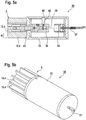
- FIG. 11 shows a cross-sectional view of an example of an X-ray tube 30 which has an anode 36 as a component that carries high voltage and warms up during operation.
- the heat sink 4 which is in the Figures 4a and 4b is shown, attached to the part of the anode 36 led out of the X-ray tube 30 in a heat-conducting manner.
- the X-ray tube is located in a tank (not shown) which is filled with oil as an insulating medium.
- oil as an insulating medium.
- the high heat capacity of the oil makes it possible with the oil, for example via a heat exchanger, to transport the heat away from the heat sink.
- air could also be used as the insulation medium. However, air has poorer cooling properties.
- the structure of the X-ray tube 30 is essentially known, the details of which are also not relevant for an understanding of the cooling body 4.
- the X-ray tube 30 essentially has an evacuated cylindrical housing 32, which also consists of a ceramic.
- a heated cathode 34 which can be contacted from the outside via corresponding bushings in the housing 32 by means of corresponding lines 37.
- the cathode 34 Opposite the cathode 34 is the anode 36, which, when the X-ray tube 30 is in operation, has a corresponding high voltage applied to it in order to accelerate the electrons emitted by the cathode 34.
- a target 38 for example made of tungsten, which is customary for generating the X-ray radiation, is located on the anode 36.
- X-rays which are generated by the electrons penetrating into the target 38 and braked by it, leave the X-ray tube 30 through a radiation window 40 in the housing 32.
- a titanium foil 42 can be arranged in the beam path for hardening the X-rays.
- connection end of the cathode 34 is led out at the front end 43 of the housing 32.
- the heat sink 4 is connected to the anode 36 in order to dissipate the heat during operation with good thermal conductivity.
- FIG. 9 shows, in addition and for better illustration, a perspective view of the X-ray tube 30 of FIG Figure 5a .
Landscapes
- X-Ray Techniques (AREA)
- Cooling Or The Like Of Semiconductors Or Solid State Devices (AREA)
Description
- Die vorliegende Erfindung betrifft allgemein eine Röntgenröhre mit einer im Betrieb eine Hochspannung, bevorzugt mehr als 120 kV, besonders bevorzugt mehr als 300 kV, führenden und sich erwärmenden Anode. Im Besonderen betrifft die Erfindung eine Röntgenröhre mit einem Kühlkörper, der bei begrenzten Platzverhältnissen zur Kühlung der Hochspannung führenden Anode geeignet ist.
- Röntgenröhren als Beispiel für eine Vorrichtung zur Erzeugung von Röntgenstrahlen (Röntgenstrahlungserzeuger) sind bekannt. Zur Vermeidung von Spannungsüberschlägen ist es erforderlich, Hochspannung führende Teile, wie die Anode, gegenüber anderen Teilen in der Umgebung mittels ausreichender Isolation zu isolieren.
-
DD 139 327 A DE 10 2008 006 620 A1 zeigt eine Röntgenröhre, bei das röhrenförmige Gehäuse der Röhre aus einer Keramik besteht. In dem Gehäuse sind die Baugruppen zur Erzeugung der Röntgenstrahlen angeordnet. Die Anode einer Röntgenröhre erwärmt sich im Betrieb, zur Vermeidung von Überhitzungsschäden wird die Wärme von der Anode üblicherweise über einen Kühlkörper abgeführt. - Passive Kühlkörper vergrößern die wärmeabgebende Oberfläche eines Wärme produzierenden Bauteils und sind grundsätzlich bekannt; beispielsweise aus dem
DE 20 2007 007 568 U1 . - Bekannte Kühlkörper bestehen üblicherweise aus einem gut wärmeleitfähigen Metall, beispielsweise Aluminium oder Kupfer. Bei einem aus Metall bestehenden Kühlkörper auf dem außerhalb des Gehäuses der Röntgenröhre liegenden Teil der Anode ist zwischen dem Kühlkörper und anderen auf einem Bezugspotenzial (z. B. Masse, GND etc.) liegenden Bauteilen oder Gehäuseteilen ein Mindestabstand einzuhalten, um Spannungsüberschläge zu verhindern. Wenn die Röntgenröhre mit höheren Spannungen betrieben werden soll, muss dieser Sicherheitsabstand entsprechend erhöht werden. Dies kann eine Vergrößerung des Außengehäuses einer Anlage, in der die Röntgenröhre angeordnet ist, erfordern.
- Eine Isolationshülse, wie bei der
DD 139 327 A - Grundsätzlich ist bei vielen Vorrichtungen die Designanforderung "so kompakt wie möglich". Die Größe eines Röntgengenerators wird nach unten dadurch begrenzt, dass bestimmte Komponenten integriert werden müssen und die Abstände zwischen den Komponenten, die auf unterschiedlichem elektrischen Potential liegen, so gewählt werden müssen, dass an keiner Stelle die Durchschlagsfestigkeit der Isolationsmedien überschritten wird.
-
JP 2009 164038 A WO 2013/021794 A1 . -
US 2003/221816 A1 zeigt einen Kühlkörper mit metallischem Grundkörper und keramischen plattenförmigen Wärmeabgabeelementen. Ähnliche Anordnungen zeigt dieCN 202 221 659 U , wobei dort auch stiftförmige Wärmeabgabeelementen gezeigt sind. -
WO 2012/031943 A1 zeigt u.a. zylindrische Kühlkörper, bei denen ein metallischer Grundkörper an keramische plattenförmigen Wärmeabgabeelemente angegossen sind. - Es ist eine Aufgabe der Erfindung eine Röntgenröhre, insbesondere Vakuumröntgenröhre, mit einer im Betrieb eine Hochspannung, bevorzugt mehr als 120 kV, besonders bevorzugt mehr als 300 kV, führenden und sich erwärmenden Anode vorzuschlagen, bei der die Durschlagfestigkeit der Anode , die mit höheren Spannungen betrieben wird, gegenüber der Umgebung verbessert ist.
- Die Aufgabe wird mit den Merkmalen des unabhängigen Anspruchs 1 gelöst. Ausführungsbeispiele und vorteilhafte Weiterbildungen sind in den sich anschließenden Unteransprüchen definiert.
- Ein Kerngedanke der Erfindung besteht darin, einen Grundkörper eines Kühlkörpers als Schnittstelle zu der zu kühlenden Anode, welche bevorzugt aus Metall besteht, aus einem gut Wärme leitenden Metall, wie z. B. Aluminium (Al) oder Kupfer (Cu), auszuführen und an dem Grundkörper zur Vergrößerung der Oberfläche als Wärmeübergang zur Umgebung Wärmeabgabeelemente, wie z. B. Kühlstifte und/oder Kühlrippen aus einer Wärme gut leitenden, aber elektrisch isolierenden Keramik, wie z. B. Aluminiumnitrid (AIN) oder Siliziumkarbid (SiC), anzuordnen. Durch diesen speziellen Aufbau des Kühlkörpers können vorteilhaft drei Anforderungen erfüllt werden: (i) das Bauteil, an dem der Kühlkörper angebracht ist, kann durch Wärmestrahlung und vor allem Konvektion gekühlt werden; (ii) gegenüber benachbarten Bauteilen, die auf unterschiedlichem elektrischem Potenzial liegen, ist die Isolationsstrecke - im Vergleich z. B. mit einem herkömmlichen Ganzmetall- oder Vollmetall-Kühlkörper - erhöht; und (iii) Spannungsprobleme, die sich durch unterschiedliche Wärmeausdehnungskoeffizienten zwischen dem zu kühlenden Bauteil und der Keramik ergeben würden, können durch den Grundkörper als Übergangsstück ausgeglichen werden. Schließlich macht die Kombination aus kostengünstigen Bestandteilen und der zusätzlichen Funktion der elektrischen Isolation den erfindungsgemäßen Kühlkörper gegenüber bekannten Kühlkörpern aus Aluminium oder Keramik überlegen.
- Der Grundkörper kann aus einem Metall mit guten Wärmeleiteigenschaften bestehen. Bevorzugt besteht der Grundkörper aus einem Metall oder einer Metalllegierung mit einem Wärmeleitkoeffizienten von mindestens 100 W/ (m K), bevorzugt von mehr als 200 W/ (m K). Beispielsweise eignen sich als Metall Aluminium (AI), Kupfer (Cu), Silber (Ag) oder Legierung dieser Metalle.
- Das Material der elektrisch isolierenden Wärmeabgabeelemente weist bevorzugt einen Wärmeleitkoeffizienten von mehr als 100 W/ (m K) auf. Elektrisch isolierend bedeutet hier, dass das Material einen spezifischen Widerstand von wenigstens 1012 Ω*m/mm2 und mehr aufweist. Die Wärmeabgabeelemente bestehen bevorzugt aus einer Keramik. Beispielsweise eignet sich als Keramik Siliziumkarbid (SiC) oder Aluminiumnitrid (AIN).
- Geeignete Kombinationen hinsichtlich der Materialwahl für den Grundkörper und die Wärmeabgabeelemente sind beispielsweise Kupfer/Siliziumkarbid oder Aluminium/Aluminiumnitrid.
- Die Wärmeabgabeelemente sind plattenförmig. D. h., die Wärmeabgabeelemente weisen die Formen von Platten auf.
- Der Grundkörper weist für jedes Wärmeabgabeelement eine entsprechende Aufnahme oder Ausnehmung auf. Die jeweilige Aufnahme oder Ausnehmung ist entsprechend der Form eines Verbindungsabschnitts eines einzufügenden Wärmeabgabeelements dimensioniert.
- Die Wärmeabgabeelemente, d. h. die Verbindungsabschnitte, sind mit dem Grundkörper kraftschlüssig verbunden. Dazu ist der jeweilige Verbindungsabschnitt mittels einer Presspassung oder Klemmung in der zugehörigen Aufnahme befestigt. Um das in Bezug auf die Aufnahme mit Übermaß gefertigte keramische Wärmeabgabeelement in die Aufnahme im metallischen Grundkörper einfügen zu können, kann der Grundkörper erwärmt werden. Beim Erkalten des Grundkörpers bildet sich dann die Pressverbindung quasi durch Aufschrumpfen des Grundkörpers auf den Verbindungsabschnitt des Wärmeabgabeelements. Da Keramik sehr gut Druckkräfte aufnehmen kann, kommt diese Verbindung den Festigkeitseigenschaften der Keramik entgegen. Durch die Presspassung werden auf den in Bezug auf den Grundkörper innenliegenden Verbindungsabschnitt Druckkräfte induziert, sodass der Verbund Metall/Keramik die durch die Pressung erzeugten Spannungen problemlos aufnehmen kann. Zusätzlich wird mit der Presspassung ein besonders guter Wärmeübergang vom Grundkörper auf die Wärmeabgabeelemente erreicht.
- Der Grundkörper des Kühlkörpers kann grundsätzlich ein CNC-gefertigtes Metallteil sein.
- Der Grundkörper des Kühlkörpers für die Anode kann röhrförmig sein, insbesondere zylinderförmig. Ist der Grundkörper im Wesentlichen ein Zylinder, kann er als Drehkörper hergestellt werden. Die Wärmeaufnahmefläche wird von einer Innenoberfläche einer axial im Grundkörper verlaufenden Ausnehmung gebildet. Die Form der Ausnehmung ist zur Kopplung mit der Anode als Wärmequelle angepasst. Die restliche Oberfläche des Grundkörpers ist wieder Teil der Wärmeabgabefläche, in der die Aufnahmen für die Wärmeabgabeelemente ausgebildet sind. In jeder dieser Aufnahmen ist bevorzugt ein Wärmeabgabeelement eingefügt und gut Wärme leitend befestigt.
- Die Ausnehmungen sind in der Außenfläche des Grundkörpers als axial verlaufende Schlitze oder Nuten ausgeführt. In diese Ausnehmungen sind die plattenförmigen Keramikelemente als Wärmeabgabeelemente formschlüssig und kraftschlüssig eingefügt.
- Die Röntgenröhre mit dem erfindungsgemäßen Kühlkörper ist eine elektrische Vorrichtung, die ein im Betrieb eine Hochspannung führendes und sich erwärmendes Bauteil aufweist, wobei der Kühlkörper mit diesem Bauteil Wärme leitend verbunden ist.
- Die Röntgenröhre weist die Anode als ein im Betrieb eine Hochspannung führendes und sich erwärmendes Bauteil auf. Mit der Anode ist ein Kühlkörper Wärme leitend verbunden. Bevorzugt weisen die Wärmeabgabeelemente ausgehend vom Grundkörper des Kühlkörpers eine Höhe auf. In der erfindunggemäßen Röntgenröhre ist die Höhe so dimensioniert, dass bei Berücksichtigung der Hochspannung und ggf. eines die Wärmeabgabeelemente umgebenden Isolationsmediums eine vorbestimmte ausreichende Durchschlagsfestigkeit gegenüber der Umgebung erreicht bzw. sichergestellt wird.
- In der Praxis wird die Größe der Röntgenröhre nach unten dadurch begrenzt, dass bestimmte Komponenten integriert werden müssen und die Abstände zwischen den Komponenten, die auf unterschiedlichem elektrischem Potential liegen, so gewählt werden müssen, dass die Durchschlagsfestigkeit des dazwischen angeordneten Isolationsmediums nicht überschritten wird. Das zu kühlende Bauteil ist hier im Wesentlichen die Anode der Röntgenröhre. Besonders vorteilhaft dient der Grundkörper des Kühlkörpers dabei als Übergangsstück zwischen der sich im Betrieb erwärmenden Anode (als Wärme erzeugendes Bauteil) und den keramischen Wärmeabgabeelementen, die als Kühlrippen fungieren.
- Da die Anode im Anschlussbereich üblicherweise rotationssymmetrisch ist, kann der Grundkörper des Kühlkörpers besonders einfach als Drehkörper gefertigt werden.
- Um die Isolationselemente mit dem Grundkörper zusammenzufügen, können in den Grundkörper Schlitze oder Nuten mittels einer CNC-Maschine eingearbeitet werden. Die Schlitze oder Nuten sind entsprechend der gewählten Fügetechnik auf die Abmessungen der Verbindungsabschnitte der Wärmeabgabeelemente abgestimmt. Keramikplatten eignen sich besonders als Wärmeabgabeelemente, da diese als kostengünstige Massenartikel erhältlich sind.
- Weitere Vorteile, Merkmale und Einzelheiten der Erfindung ergeben sich aus der nachfolgenden Beschreibung, in der unter Bezugnahme auf die Zeichnungen Ausführungsbeispiele der Erfindung, wie sie in den Ansprüchen definiert ist, sowie Beispielen, die nicht unter die Erfindung fallen, aber zum besseren Verständnis der Erfindung beitragen, im Einzelnen beschrieben sind. Dabei können die in den Ansprüchen und in der Beschreibung erwähnten Merkmale jeweils einzeln für sich oder in beliebiger Kombination erfindungswesentlich sein. Ebenso können die vorstehend genannten und die hier weiter ausgeführten Merkmale je für sich oder zu mehreren in beliebigen Kombinationen Verwendung finden. Funktionsähnliche oder identische Bauteile oder Komponenten sind teilweise mit gleichen Bezugszeichen versehen. Die in der Beschreibung der Ausführungsbeispiele verwendeten Begriffe "links", "rechts", "oben" und "unten" beziehen sich auf die Zeichnungen in einer Ausrichtung mit normal lesbarer Figurenbezeichnung bzw. normal lesbaren Bezugszeichen. Die gezeigten und beschriebenen Ausführungsformen sind nicht als abschließend zu verstehen, sondern haben beispielhaften Charakter zur Erläuterung der Erfindung. Die detaillierte Beschreibung dient der Information des Fachmanns, daher werden bei der Beschreibung bekannte Schaltungen, Strukturen und Verfahren nicht im Detail gezeigt oder erläutert, um das Verständnis der vorliegenden Beschreibung nicht zu erschweren.
-
Figur 1a, 1b zeigen ein erstes Beispiel eines Kühlkörpers. -
Figur 2a, 2b zeigen ein zweites Beispiel eines Kühlkörpers. -
Figur 3a, 3b zeigen ein drittes Beispiel eines Kühlkörpers. -
Figur 4a zeigt ein Ausführungsbeispiel eines Kühlkörpers mit zylinderförmigem Grundkörper aus Metall und Kühlrippen aus Keramik. -
Fig. 4b zeigt die Querschnittsansicht AA derFigur 4a . -
Fig. 5a zeigt eine Querschnittsansicht einer Röntgenröhre mit dem Kühlkörper derFiguren 4a, 4b als Anodenkühlkörper. -
Fig. 5b ist eine perspektivische Ansicht der Röntgenröhre derFigur 5a . - Die
Figuren 1a bis 3b zeigen drei Beispiele für Kühlkörper 1, 2 und 3 mit jeweils einem Grundkörper 10.1, 10.2, 10.3 aus Metall. - Der Grundkörper weist jeweils eine Wärmeaufnahmefläche 12.1, 12.2, 12.3 zur Kopplung mit einer Wärmequelle auf. Die Wärmequelle kann ein Bauteil sein, welches sich im Betrieb erwärmt oder erwärmt wird. Im Betrieb wird Wärme in bekannter Weise durch Wärmeleitung in den Grundkörper des Kühlkörpers geleitet. Mit anderen Worten entspricht die Wärmeaufnahmefläche im Wesentlichen der Kontaktfläche mit der Wärmequelle.
- Der Grundkörper 10.1, 10.2, 10.3 kann über seine Außenflächen, die nicht mit der Wärmequelle in Kontakt stehen, als Wärmeabgabefläche die Wärme an ein die Wärmeabgabeflächen umgebendes Isolationsmedium (üblicherweise ein Fluid, wie z. B. im einfachsten Fall die Umgebungsluft) durch Wärmeleitung, Wärmestrahlung und Konvektion abgeben. Im Wesentlichen bildet der Teil der Außenfläche des Grundkörpers 10.1, 10.2, 10.3, welcher der Wärmeaufnahmefläche 12.1, 12.2, 12.3 gegenüberliegt die Wärmeabgabefläche 14.1, 14.2, 14.3 des Grundkörpers 10.1, 10.2, 10.3.
- Zur Vergrößerung der wirksamen Wärmeabgabefläche sind an dem Grundkörper 10.1, 10.2, 10.3 im Bereich der Wärmeabgabefläche 14.1, 14.2, 14.3 mit Wärmeabgabeelementen 16.1, 16.2, 16.3 angeordnet, die Wärme leitend mit dem Grundkörper 10.1, 10.2, 10.3 verbunden sind. Die Wärmeabgabefläche 14.1, 14.2, 14.3 des Grundkörpers 10.1, 10.2, 10.3 wird so um die Oberflächen der Wärmeabgabeelemente 16.1, 16.2, 16.3 erhöht. Die Wärmeabgabeelemente 16.1, 16.2, 16.3 sind aus einem elektrisch isolierenden Material gefertigt, welches bevorzugt eine Wärmeleitfähigkeit in der Größenordnung des Metalls des Grundkörpers 10.1, 10.2, 10.3 aufweist. Die Wärmeabgabeelemente 16.1, 16.2, 16.3 sind in entsprechend geformte Aufnahmen 18.1, 18.2, 18.3, die in dem Grundkörper 10.1, 10.2, 10.3 ausgeformt sind, mit jeweiligen Verbindungsabschnitten 20.1, 20.2, 20.3 in den Grundkörper 10.1, 10.2, 10.3 Wärme leitend eingefügt.
-
Figur 1a zeigt das erste Beispiel des Kühlkörpers 1 mit plattenförmigen Wärmeabgabeelementen 16.1.Figur 1b zeigt eines der Wärmeabgabeelemente 16.1 derFigur 1a in Alleinstellung. Das Wärmeabgabeelement 16.1 hat die Form einer Platte, d. h., es ist plattenförmig. - Plattenförmig bedeutet, dass das Wärmeabgabeelement 16.1 im Wesentlichen im Vergleich zur Breite deutlich größere Abmessungen in der Länge und Höhe aufweist.
- Das plattenförmige Wärmeabgabeelement 16.1 besitzt eine Breite B und eine Höhe, die sich aus einer Höhe h des Verbindungsabschnitts 20.1 und der restlichen nach Einfügung in den Grundkörper 10.1 aus diesem herausragenden Abschnitt mit der Länge H zusammensetzt. Die Längserstreckung des Wärmeabgabeelements 16.1 ist mit L gekennzeichnet. Da B<< L und B<<(h+H) ist, ist das Wärmeabgabeelement plattenförmig.
- Mit dem Verbindungsabschnitt 20.1 ist das Wärmeabgabeelement 16.1 in den Grundkörper 10.1 in die dort entsprechend eingearbeiteten oder ausgebildeten Ausnehmungen 18.1 eingefügt und darin jeweils mit einem der weiter unten noch zu besprechenden Maßnahmen Wärme leitend befestigt.
-
Figur 2a zeigt das zweite Beispiel des Kühlkörpers 2. Hier sind die Wärmeabgabeelemente 16.2 aus einem elektrisch isolierenden Material bestehende Stifte oder Stäbe, die wieder eine Wärmeleitfähigkeit in der Größenordnung des Metalls des Grundkörpers 10.2 aufweisen. Ähnlich wie in derFigur 1a sind die stiftförmigen oder stabförmigen Wärmeabgabeelemente 16.2 mit einem jeweiligen Verbindungsabschnitt 20.2 in entsprechend eingearbeitete oder ausgeformte Ausnehmungen 18.2 in den Grundkörper 10.2 eingefügt und dort gut Wärme leitend befestigt. - In der
Figur 2b ist eines der stiftförmigen Wärmeabgabeelemente 16.2 in Alleinstellung gezeigt. Das Wärmeabgabeelement 16.2 ist im Wesentlichen zylinderförmig und besitzt eine Länge L und einen Durchmesser D. Die Länge L setzt sich aus dem Verbindungsabschnitt 20.2, der ähnlich wie inFigur 1a bzw. 1b die Länge h aufweist, die der Tiefe jeweils einer der Aufnahmen 18.2 im Grundkörper 10 entspricht. Der übrige Teil des stiftförmigen Wärmeabgabeelements 16.2 besitzt die Länge H, die bei in den Grundkörper 10.2 eingefügtem Wärmeabgabeelement 16.2 aus dem Grundkörper 10.2 herausragt; d. h., L ist hier (h+H). -
Figur 3a zeigt das dritte Beispiel des Kühlkörpers 3. Hier sind in die Wärmeabgabefläche 14.3 des Grundkörpers 10.3 (wie im ersten und zweiten Ausführungsbeispiel) Aufnahmen 18.3 ausgebildet, in die rohrförmige Wärmeabgabeelemente 16.3 eingefügt und befestigt sind. Die rohrförmigen Wärmeabgabeelemente 16.3 bestehen wieder aus einem elektrisch isolierenden Material, das eine Wärmeleitfähigkeit in der Größenordnung des Metalls des Grundkörpers 10.3 aufweist. Die rohrförmigen Wärmeabgabeelemente 16.3 besitzen im Ausführungsbeispiel die Form eines hohlen Zylinders mit einem Außendurchmesser D und einem Innendurchmesser d sowie einer Länge L. Die Länge des Wärmeabgabeelements 16.3 unterteilt sich wieder in den Verbindungsabschnitt 20.3 mit einer Länge h, der in die entsprechend ausgebildeten Aufnahmen 18.3 des Grundkörpers 10.3 mit einer Tiefe h eingefügt sind. Der restliche Abschnitt des Wärmeabgabeelements 16.3, welches bei in den Grundkörper 10.3 eingefügtem Wärmeabgabeelement 16.3 aus dem Grundkörper 10.3 herausragt, besitzt die Länge H; d. h., hier ist L - ähnlich wie in denFiguren 2a, 2b - gleich (h+H). - Wie bereits angesprochen ist bei den, mit den
Figuren 1a bis 3b beschriebenen Kühlkörpern 1, 2 und 3, der Grundkörper 10.1, 10.2, 10.3 aus einem gut Wärme leitenden Metall, bevorzugt mit einem Wärmeleitkoeffizienten von 100 W/ (m K) oder mehr, hergestellt. Für die Ausführungsbeispiele wurde Aluminium mit einem Wärmeleitkoeffizienten von ca. 240 W/ (m K) oder Kupfer mit einem Wärmeleitkoeffizienten von ca. 400 W/ (m K) verwendet. Selbstverständlich kann der Grundkörper 10.1, 10.2, 10.3 auch aus einem anderen Metall oder einer Metalllegierung bestehen. - Die Wärmeabgabeelemente 16.1, 16.2 und 16.3 sind aus einer Keramik hergestellt, die einen Wärmeleitkoeffizienten aufweist, der in derselben Größenordnung wie der des Metalls des Grundkörpers 10.1, 10.2, 10.3 liegt. Bevorzugt besitzt die Keramik somit ebenfalls einen Wärmeleitkoeffizienten von mehr als 100 W/ (m K). Für die Ausführungsbeispiele wurde Aluminiumnitrid mit einem Wärmeleitkoeffizienten von ca. 180 bis 220 W/ (m K) oder Siliziumkarbid mit einem Wärmeleitkoeffizienten von ca. 350 W/(mK) verwendet.
- Wie in den
Figuren 1a ,2a und3a zu erkennen, sind die Wärmeabgabeelemente 16.1, 16.2 und 16.3 jeweils in entsprechende Aufnahmen 18.1, 18.2 und 18.3, die in den Grundkörper 10.1, 10.2, 10.3 eingearbeitet sind, eingesetzt. Um eine besonders gut Wärme leitende und ausreichende Befestigung der Wärmeabgabeelemente 16.1, 16.2 und 16.3 sicherzustellen, können verschiedene Fügetechniken zur Anwendung kommen. - Beispielsweise kann bei den in den
Figuren 1a und2a gezeigten Beispielen das jeweilige Wärmeabgabeelement 16.1 oder 16.2 mit dem Grundkörper 10.1, 10.2 formschlüssig und/oder kraftschlüssig verbunden sein, indem der jeweilige Verwendungsabschnitt 20.1, 20.2 in der zugehörigen Aufnahme 18.1, 18.2 durch eine Presspassung oder mittels Klemmung befestigt ist. Zum Einfügen der Wärmeabgabeelemente in die entsprechenden Aufnahmen im Grundkörper 10.1, 10.2 kann beispielsweise der Grundkörper 10.1, 10.2 entsprechend erwärmt werden, sodass sich der Grundkörper 10.1, 10.2 ausdehnt. In diesem Zustand können die keramischen Wärmeabgabeelemente 16.1, 16.2 in die jeweiligen Aufnahmen 18.1, 18.2 eingesetzt werden. Sobald der Grundkörper 10.1, 10.2 sich wieder abgekühlt hat, sind die Wärmeabgabeelemente 16.1, 16.2 mit dem Grundkörper 10.1, 10.2 fest verbunden. Hierbei ist lediglich sicherzustellen, dass die Abmessungen der Ausnehmungen 18.1, 18.2 so dimensioniert werden, dass die Wärmeabgabeelemente 16.1, 16.2 bei den im bestimmungsgemäßen Betrieb erreichten Temperaturen durch Ausdehnung des Metalls des Grundkörpers 10.1, 10.2 sich nicht lockern können. - Eine alternative Befestigungsvariante ist bei den Beispielen der
Figuren 2a und3a möglich. Dazu kann an den Wärmeabgabeelementen 16.2, 16.3, wenigstens im Bereich des jeweiligen Verbindungsabschnitts 20.2, 20.3 ein erstes Gewinde eingearbeitet oder ausgeformt sein (nicht dargestellt). In die entsprechenden Aufnahmen 18.2, 18.3 im Grundkörper 10.2, 10.3, die dann als Löcher ausgeformt sind, können dann korrespondierende zweite Gewinde eingearbeitet sein. Entsprechend können die Wärmeabgabeelemente 16.2, 16.3 mit dem Grundkörper 10.2, 10.3 verbunden werden, indem die jeweiligen Verbindungsabschnitte 20.2, 20.3 in die jeweilige Aufnahme 18.2, 18.3 durch Einschrauben befestigt werden. Wenn sich im Betrieb des Kühlkörpers der Grundkörper 10.2, 10.3 erwärmt und dabei ausdehnt, werden die keramischen Wärmeabgabeelemente 16.2, 16.3 nur auf Druck belastet, wodurch sich der Wärmeübergangswiderstand zwischen dem Grundkörper und den Wärmeabgabeelementen zusätzlich verringert. - Alternativ können die Wärmeabgabeelemente 16.1, 16.2 oder 16.3 der Beispiele der
Figuren 1a bis 3a in dem jeweiligen Grundkörper 10.1, 10.2, 10.3 durch Eingießen verbunden werden. Hierbei werden die jeweils im Grundkörper 10.1, 10.2, 10.3 eingearbeiteten Aufnahmen 18.1, 18.2, 18.3 und/oder die Abmessungen des jeweiligen Verbindungsabschnitts 20.1, 20.2, 20.3 so dimensioniert, dass zwischen Grundkörper 10.1, 10.2, 10.3 und Wärmeabgabeelement 16.1, 16.2, 16.3 nach einem Einfügen ein Zwischenraum gebildet wird. Dieser Zwischenraum zwischen dem jeweiligen Verbindungsabschnitt 20.1, 20.2, 20.3 und der jeweiligen Aufnahme 18.1, 18.2, 18.3 kann mit einer gut Wärme leitenden und sich verfestigenden, bevorzugt aushärtenden, Vergussmasse aufgefüllt oder ausgefüllt werden. Nach Verfestigen oder Aushärten der Vergussmasse ist das jeweilige Wärmeabgabeelement mit dem Grundkörper 10.1, 10.2, 10.3 fest verbunden. - Eine weitere Alternative der Befestigung der Wärmeabgabeelemente 16.1, 16.2, 16.3 in den jeweiligen in den Grundkörpern 10.1, 10.2, 10.3 vorgesehenen Aufnahmen 18.1, 18.2, 18.3 kann durch Verkleben bzw. Einkleben mit einem geeigneten Klebstoff erfolgen.
- Eine weitere Verbindungsmöglichkeit zwischen den Wärmeabgabeelementen 16.1, 16.2, 16.3 in den im jeweiligen Grundkörper 10.1, 10.2, 10.3 eingearbeiteten Aufnahmen 18.1, 18.2, 18.3 ist Löten. Dazu wird das jeweilige Wärmeabgabeelement 16.1, 16.2, 16.3 nach Einfügen in die entsprechende Aufnahme 18.1, 18.2, 18.3 im Grundkörper 10.1, 10.2, 10.3 mit einem geeigneten Lot mit dem Grundkörper 10.1, 10.2, 10.3 in an sich bekannter Weise verlötet.
- In einer Weiterbildung ist, um eine bessere Benetzung des Wärmeabgabeelements 16.1, 16.2, 16.3 aus Keramik mit Lot zu erreichen, dieses, bevorzugt nur im Bereich des Verbindungsabschnitts 20.1, 20.2, 20.3, zuvor metallisiert worden.
-
Figur 4a zeigt ein Ausführungsbeispiel eines erfindungsgemäßen Kühlkörpers 4. Grundsätzlich gilt das vorstehend zu den Beispielen derFiguren 1a bis 3b Gesagte für das Ausführungsbeispiel entsprechend. - Der Grundkörper 10.4 des Ausführungsbeispiels ist im Vergleich zu den Grundkörpern 10.1, 10.2, 10.3 der vorstehenden Beispiele rotationssymmetrisch. Der Grundkörper 10.4 kann als Drehkörper oder mittels einer CNC-Maschine hergestellt werden.
- Der Grundkörper 10.4 besitzt eine Innenoberfläche 12.4 einer im Grundkörper 10.4 axial verlaufenden Ausnehmung 22. Die Innenoberfläche 12.4 dient wieder zur Kopplung mit einer Wärmequelle, von der Wärme über den Kühlkörper abgeführt werden soll.
- Die Außenoberfläche 14.4 des Grundkörpers 10.4 ist Teil der Wärmeabgabefläche, in die Aufnahmen 18.4 für Wärmeabgabeelemente 16.4 eingearbeitet sind. Die Aufnahmen 18.4 sind als axial verlaufende Schlitze in den Grundkörper 10.4, beispielsweise durch Fräsen, eingearbeitet.
- In die axial verlaufenden Schlitze sind plattenförmige Keramikelemente als die Wärmeabgabeelemente 16.4 zur Vergrößerung der effektiven Wärmeabgabefläche eingefügt. Die Wärmeabgabeelemente 16.4 sind über den gesamten Umfang des Grundkörpers 10.4 sternförmig und gleichmäßig beabstandet angeordnet. Somit wird über den gesamten Umfangsbereich des Grundkörpers 10.4 eine gleichmäßige Vergrößerung der effektiven Wärmeabgabeoberfläche erreicht.
- Der in den
Figuren 4a und 4b gezeigte Kühlkörper 4 eignet sich beispielsweise besonders gut als Kühlkörper für eine Anode einer Röntgenröhre als Röntgenstrahlungserzeuger, wie sie beispielsweise aus derDE 10 2008 006 620 A1 bekannt ist.Figur 5a zeigt eine Querschnittsansicht eines Beispiels einer Röntgenröhre 30, die eine Anode 36 als ein im Betrieb Hochspannung führendes und sich erwärmendes Bauteil aufweist. Zur Kühlung der Anode 36 im Betrieb der Röntgenröhre 30 ist der Kühlkörper 4, der in denFiguren 4a und 4b gezeigt ist, an dem aus der Röntgenröhre 30 herausgeführten Teil der Anode 36 Wärme leitend befestigt. Zur Ableitung der Wärme vom Kühlkörper befindet sich die Röntgenröhre in einem Tank (nicht dargestellt) der mit Öl als Isolationsmedium gefüllt ist. Die hohe Wärmekapazität des Öls ermöglicht es mit dem Öl, beispielsweise über einen Wärmetauscher, die Wärme vom Kühlkörper weg zu transportieren. Grundsätzlich könnte als Isolationsmedium auch Luft eingesetzt werden. Luft hat allerdings schlechtere Kühleigenschaften. - Der Aufbau der Röntgenröhre 30 ist im Wesentlichen bekannt, wobei Einzelheiten für das Verständnis des Kühlkörpers 4 auch nicht relevant sind. Die Röntgenröhre 30 besitzt im Wesentlichen ein evakuiertes zylinderförmiges Gehäuse 32, welches ebenfalls aus einer Keramik besteht. In dem Gehäuse 32 befindet sich zum einen eine beheizte Kathode 34, die von außen über entsprechende Durchführungen im Gehäuse 32 mittels entsprechender Leitungen 37 kontaktierbar ist. Gegenüber der Kathode 34 befindet sich die Anode 36, die im Betrieb der Röntgenröhre 30 mit einer entsprechenden Hochspannung zur Beschleunigung der von der Kathode 34 emittierten Elektronen beaufschlagt wird. An der Anode 36 befindet sich ein zu Erzeugung der Röntgenstrahlung übliches Target 38, beispielsweise aus Wolfram. Röntgenstrahlen, die durch die in das Target 38 eindringenden und davon abgebremsten Elektronen erzeugt werden, verlassen die Röntgenröhre 30 durch ein Strahlungsfenster 40 im Gehäuse 32. Im Strahlengang kann zur Aufhärtung der Röntgenstrahlen eine Titanfolie 42 angeordnet sein.
- An dem stirnseitigen Ende 43 des Gehäuses 32 ist das Anschlussende der Kathode 34 herausgeführt. An dieser Stelle ist der Kühlkörper 4 mit der Anode 36 zur Abführung der im Betrieb stehenden Wärme gut Wärme leitend verbunden angeordnet.
-
Figur 5b zeigt ergänzend und zur besseren Veranschaulichung eine perspektivische Ansicht der Röntgenröhre 30 derFigur 5a .
Claims (5)
- Röntgenröhre (30) mit einer im Betrieb eine Hochspannung führenden und sich erwärmenden Anode (36),
wobei mit der Anode ein Kühlkörper (4) Wärme leitend verbunden ist, der einen Grundkörper (10.4) aus einem Metall mit einer Wärmeaufnahmefläche (12.4) zur Kopplung mit der Anode (36) als Wärmequelle (36) und einer Wärmeabgabefläche (14.4), die durch mit dem Grundkörper (10.4) verbundene Wärmeabgabeelemente (16.4) vergrößert ist, aufweist,
wobei die Wärmeabgabeelemente (16.4) aus einem elektrisch isolierenden Material bestehen, welches eine Wärmeleitfähigkeit in der Größenordnung des Metalls des Grundkörpers (10.4) aufweist, wobei die Röntgenröhre ein die Wärmeabgabeelemente umgebendes Isolationsmedium aufweist,
wobei die Wärmeabgabeelemente (16.4) ausgehend von dem Grundkörper (10.4) des Kühlkörpers (4) eine Höhe (H) aufweisen, sodass unter Berücksichtigung der Hochspannung und des die Wärmeabgabeelemente (16.4) umgebenden Isolationsmediums eine ausreichende Durchschlagsfestigkeit gegenüber der Umgebung der Röntgenröhre (30) besteht,
wobei der Grundkörper (10.4) ein Drehkörper mit einer Innenoberfläche (12.4) einer axial verlaufenden Ausnehmung (22), die zur Kopplung mit der Anode (36) als die Wärmequelle angepasst ist,
wobei die Wärmeabgabeelemente (16.4) plattenförmige Keramikelemente sind, dadurch gekennzeichnet, dass der Grundkörper (10.4) für jedes Wärmeabgabeelement (16.4) eine entsprechend Aufnahme (18.4) aufweist, die zur Aufnahme (18.4) eines Verbindungsabschnitts (20.4) jeweils eines der Wärmeabgabeelemente (16.4) dimensioniert ist,
der Grundkörper (10.4) eine Außenoberfläche (14.4) als Teil der Wärmeabgabefläche die Aufnahmen (18.4) für die Wärmeabgabeelemente (16.4) aufweist und in jeder der Aufnahmen (18.4) ein Wärmeabgabeelement (16.4) eingefügt ist,
die Aufnahmen (18.4) axial verlaufende Schlitze oder Nuten sind, in die die plattenförmige Keramikelemente als die Wärmeabgabeelemente (16.4) eingefügt sind,
die Wärmeabgabeelemente (16.4) mit dem Grundkörper (10.4) verbunden sind, indem der jeweilige Verbindungsabschnitt (20.4) mittels einer Presspassung oder Klemmung in der zugehörigen Aufnahme (18.4) befestigt ist. - Röntgenröhre (30) nach Anspruch 1, wobei der Grundkörper (10.4) aus einem Metall oder einer Metalllegierung besteht.
- Röntgenröhre (30) nach Anspruch 2, wobei der Grundkörper (10.4) aus einem Metall besteht und das Metall Aluminium, Kupfer oder Silber ist, und/oder das Metall oder die Metalllegierung einen Wärmeleitkoeffizienten im Bereich von 100 bis 450 W/ (m K) aufweist.
- Röntgenröhre (30) nach einem der vorhergehenden Ansprüche 1-3, wobei die Wärmeabgabeelemente (16.4) aus einer Keramik bestehen.
- Röntgenröhre (30) nach Anspruch 4, wobei die Wärmeabgabeelemente (16.4) aus einer Keramik bestehen und die Keramik Siliziumkarbid oder Aluminiumnitrid ist, und/oder die Keramik einen Wärmeleitkoeffizienten im Bereich von 100 bis 350 W/ (m K) aufweist.
Applications Claiming Priority (2)
| Application Number | Priority Date | Filing Date | Title |
|---|---|---|---|
| DE102014222164.1A DE102014222164A1 (de) | 2014-10-30 | 2014-10-30 | Kühlkörper, insbesondere für die Anode eines Röntgenstrahlungserzeugers |
| PCT/EP2015/075271 WO2016066810A1 (de) | 2014-10-30 | 2015-10-30 | Röntgenstrahlungserzeuger |
Publications (2)
| Publication Number | Publication Date |
|---|---|
| EP3213338A1 EP3213338A1 (de) | 2017-09-06 |
| EP3213338B1 true EP3213338B1 (de) | 2021-03-31 |
Family
ID=55173818
Family Applications (1)
| Application Number | Title | Priority Date | Filing Date |
|---|---|---|---|
| EP15825793.1A Active EP3213338B1 (de) | 2014-10-30 | 2015-10-30 | Röntgenstrahlungserzeuger |
Country Status (4)
| Country | Link |
|---|---|
| US (1) | US10522317B2 (de) |
| EP (1) | EP3213338B1 (de) |
| DE (1) | DE102014222164A1 (de) |
| WO (1) | WO2016066810A1 (de) |
Families Citing this family (5)
| Publication number | Priority date | Publication date | Assignee | Title |
|---|---|---|---|---|
| US10182490B2 (en) * | 2015-09-25 | 2019-01-15 | Moxtek, Inc. | X-ray tube integral heatsink |
| US10178748B1 (en) * | 2016-06-20 | 2019-01-08 | Moxtek, Inc. | X-ray spot stability |
| TWI755319B (zh) * | 2020-12-30 | 2022-02-11 | 立錡科技股份有限公司 | 晶片封裝結構 |
| CN115410882A (zh) * | 2021-05-28 | 2022-11-29 | 上海超群检测科技股份有限公司 | 一种x射线源绝缘散热装置及其制作方法 |
| CN115175548B (zh) * | 2022-09-07 | 2022-11-18 | 国家不锈钢制品质量监督检验中心(兴化) | 一种不锈钢制品成分分析用x荧光光谱仪 |
Family Cites Families (16)
| Publication number | Priority date | Publication date | Assignee | Title |
|---|---|---|---|---|
| DE139327C (de) | ||||
| DE1100057B (de) * | 1958-01-29 | 1961-02-23 | Siemens Ag | Waermeabgebender metallischer Koerper mit vergroesserter Oberflaeche |
| DD139327A1 (de) | 1978-09-26 | 1979-12-19 | Heinz Hocke | Strahlenschutzgehaeuse fuer roentgenroehren |
| US6807059B1 (en) * | 1998-12-28 | 2004-10-19 | James L. Dale | Stud welded pin fin heat sink |
| GB0008897D0 (en) * | 2000-04-12 | 2000-05-31 | Cheiros Technology Ltd | Improvements relating to heat transfer |
| US6918438B2 (en) * | 2002-06-04 | 2005-07-19 | International Business Machines Corporation | Finned heat sink |
| US20060191675A1 (en) * | 2003-09-22 | 2006-08-31 | Coolhead Technologies, Inc. | Apparatus and methods for warming and cooling bodies |
| US7396160B2 (en) * | 2004-07-30 | 2008-07-08 | Neurologica Corp. | Computerized tomography (CT) imaging system with monoblock X-ray tube assembly |
| DE202007007568U1 (de) | 2007-05-25 | 2007-09-20 | Boston Cool Tec Corporation, Wilmington | Eine flache Heatpipe (Wärmeleitrohr) und Kühlkörper welche diese verwenden |
| JP2009164038A (ja) * | 2008-01-09 | 2009-07-23 | Toshiba Corp | 固定陽極型x線管および一体型x線発生装置 |
| DE102008006620A1 (de) | 2008-01-29 | 2009-08-06 | Smiths Heimann Gmbh | Röntgenstrahlerzeuger sowie dessen Verwendung in einem Röntgenuntersuchungs- oder Röntgenprüfgerät |
| CN102401358B (zh) * | 2010-09-10 | 2016-08-03 | 欧司朗股份有限公司 | 冷却体的制造方法、冷却体以及具有该冷却体的照明装置 |
| KR101563521B1 (ko) * | 2011-08-05 | 2015-10-27 | 캐논 가부시끼가이샤 | 방사선 발생장치 및 방사선 촬영장치 |
| CN202221659U (zh) * | 2011-08-09 | 2012-05-16 | 莫卓荣 | 分体式陶瓷散热器 |
| DE202012010600U1 (de) * | 2012-10-27 | 2012-12-06 | Asia Vital Components Co., Ltd. | Kühlkörper |
| US10182490B2 (en) * | 2015-09-25 | 2019-01-15 | Moxtek, Inc. | X-ray tube integral heatsink |
-
2014
- 2014-10-30 DE DE102014222164.1A patent/DE102014222164A1/de not_active Ceased
-
2015
- 2015-10-30 WO PCT/EP2015/075271 patent/WO2016066810A1/de not_active Ceased
- 2015-10-30 EP EP15825793.1A patent/EP3213338B1/de active Active
- 2015-10-30 US US15/522,909 patent/US10522317B2/en active Active
Non-Patent Citations (1)
| Title |
|---|
| None * |
Also Published As
| Publication number | Publication date |
|---|---|
| WO2016066810A1 (de) | 2016-05-06 |
| EP3213338A1 (de) | 2017-09-06 |
| US10522317B2 (en) | 2019-12-31 |
| US20170338076A1 (en) | 2017-11-23 |
| DE102014222164A1 (de) | 2016-05-04 |
Similar Documents
| Publication | Publication Date | Title |
|---|---|---|
| EP2222564B1 (de) | Flugfeldbeleuchtungseinrichtung | |
| WO2016066810A1 (de) | Röntgenstrahlungserzeuger | |
| DE2647758C3 (de) | Kühlungsmodul für elektrische Bauteile | |
| WO2017102056A1 (de) | Vorrichtung zum kühlen eines elektrisch leitfähigen kontaktelements | |
| EP2114116B1 (de) | Hybridkühlung | |
| EP1445799A2 (de) | Kühleinrichtung für Halbleiter auf Leiterplatte | |
| DE102022202730B4 (de) | Röntgenhochspannungsgenerator mit einem oszillierendem Wärmerohr | |
| DE102015111541B4 (de) | Verfahren zur Herstellung einer Verbindung zwischen mindestens einem zylindrischen Elektrolytkondensator und einem Kühlkörper | |
| EP3301710A1 (de) | Wärmeleitender isolator | |
| EP2942800B1 (de) | Festanoden-röntgenröhre mit zweiteiliger hochspannungs-vakuumdurchführung | |
| DE102012209641B4 (de) | Kühlanordnung für eine mehrlagige Leiterplatte | |
| WO2019243326A1 (de) | Diodenlaseranordnung und verfahren zur herstellung einer diodenlaseranordnung | |
| DE102009060123B4 (de) | Elektrische Schaltung mit mindestens einer Leiterplatte und einer Anzahl von mit Bauelementekontaktierungen versehener elektrischer Bauelemente | |
| DE102015112031B4 (de) | Anordnung zur Verbesserung einer Strombelastbarkeit von Leiterbahnen | |
| DE102012025494B4 (de) | Diodenlasermodul und Verfahren zur Herstellung eines Diodenlasermoduls | |
| DE102005001360A1 (de) | Kühlvorrichtung, insbesondere für ein elektrisches Leistungshalbleiterbauelement | |
| EP1731862A1 (de) | Lichtquelle für die Endoskopie oder Mikroskopie | |
| DE102016000033B4 (de) | Röntgenröhre | |
| EP1961282B1 (de) | Anordnung mit zumindest einem elektronischen bauteil | |
| DE102019129586A1 (de) | Verbindungselement zum Verbinden einer Leiterplatte mit einem Kühlkörper und Verfahren zur Herstellung der Verbindung | |
| DE102009017924A1 (de) | Isolator für Röntgenröhren | |
| DE102010048529B4 (de) | Kühlkörper mit Hitzeverteiler | |
| EP3578880A1 (de) | Betriebsgerät mit wärmeleitstruktur | |
| WO2012130660A1 (de) | Entladelampenanordnung umfassend adapter und überwurfhohlzylinder | |
| AT254946B (de) | Baueinheit für Geräte der Nachrichtentechnik |
Legal Events
| Date | Code | Title | Description |
|---|---|---|---|
| STAA | Information on the status of an ep patent application or granted ep patent |
Free format text: STATUS: THE INTERNATIONAL PUBLICATION HAS BEEN MADE |
|
| PUAI | Public reference made under article 153(3) epc to a published international application that has entered the european phase |
Free format text: ORIGINAL CODE: 0009012 |
|
| STAA | Information on the status of an ep patent application or granted ep patent |
Free format text: STATUS: REQUEST FOR EXAMINATION WAS MADE |
|
| 17P | Request for examination filed |
Effective date: 20170523 |
|
| AK | Designated contracting states |
Kind code of ref document: A1 Designated state(s): AL AT BE BG CH CY CZ DE DK EE ES FI FR GB GR HR HU IE IS IT LI LT LU LV MC MK MT NL NO PL PT RO RS SE SI SK SM TR |
|
| AX | Request for extension of the european patent |
Extension state: BA ME |
|
| DAV | Request for validation of the european patent (deleted) | ||
| DAX | Request for extension of the european patent (deleted) | ||
| GRAP | Despatch of communication of intention to grant a patent |
Free format text: ORIGINAL CODE: EPIDOSNIGR1 |
|
| STAA | Information on the status of an ep patent application or granted ep patent |
Free format text: STATUS: GRANT OF PATENT IS INTENDED |
|
| INTG | Intention to grant announced |
Effective date: 20201009 |
|
| GRAS | Grant fee paid |
Free format text: ORIGINAL CODE: EPIDOSNIGR3 |
|
| GRAA | (expected) grant |
Free format text: ORIGINAL CODE: 0009210 |
|
| STAA | Information on the status of an ep patent application or granted ep patent |
Free format text: STATUS: THE PATENT HAS BEEN GRANTED |
|
| AK | Designated contracting states |
Kind code of ref document: B1 Designated state(s): AL AT BE BG CH CY CZ DE DK EE ES FI FR GB GR HR HU IE IS IT LI LT LU LV MC MK MT NL NO PL PT RO RS SE SI SK SM TR |
|
| REG | Reference to a national code |
Ref country code: GB Ref legal event code: FG4D Free format text: NOT ENGLISH Ref country code: CH Ref legal event code: EP |
|
| REG | Reference to a national code |
Ref country code: AT Ref legal event code: REF Ref document number: 1377885 Country of ref document: AT Kind code of ref document: T Effective date: 20210415 |
|
| REG | Reference to a national code |
Ref country code: DE Ref legal event code: R096 Ref document number: 502015014492 Country of ref document: DE |
|
| REG | Reference to a national code |
Ref country code: IE Ref legal event code: FG4D Free format text: LANGUAGE OF EP DOCUMENT: GERMAN |
|
| REG | Reference to a national code |
Ref country code: LT Ref legal event code: MG9D |
|
| PG25 | Lapsed in a contracting state [announced via postgrant information from national office to epo] |
Ref country code: BG Free format text: LAPSE BECAUSE OF FAILURE TO SUBMIT A TRANSLATION OF THE DESCRIPTION OR TO PAY THE FEE WITHIN THE PRESCRIBED TIME-LIMIT Effective date: 20210630 Ref country code: HR Free format text: LAPSE BECAUSE OF FAILURE TO SUBMIT A TRANSLATION OF THE DESCRIPTION OR TO PAY THE FEE WITHIN THE PRESCRIBED TIME-LIMIT Effective date: 20210331 Ref country code: FI Free format text: LAPSE BECAUSE OF FAILURE TO SUBMIT A TRANSLATION OF THE DESCRIPTION OR TO PAY THE FEE WITHIN THE PRESCRIBED TIME-LIMIT Effective date: 20210331 Ref country code: NO Free format text: LAPSE BECAUSE OF FAILURE TO SUBMIT A TRANSLATION OF THE DESCRIPTION OR TO PAY THE FEE WITHIN THE PRESCRIBED TIME-LIMIT Effective date: 20210630 |
|
| PG25 | Lapsed in a contracting state [announced via postgrant information from national office to epo] |
Ref country code: SE Free format text: LAPSE BECAUSE OF FAILURE TO SUBMIT A TRANSLATION OF THE DESCRIPTION OR TO PAY THE FEE WITHIN THE PRESCRIBED TIME-LIMIT Effective date: 20210331 Ref country code: RS Free format text: LAPSE BECAUSE OF FAILURE TO SUBMIT A TRANSLATION OF THE DESCRIPTION OR TO PAY THE FEE WITHIN THE PRESCRIBED TIME-LIMIT Effective date: 20210331 Ref country code: LV Free format text: LAPSE BECAUSE OF FAILURE TO SUBMIT A TRANSLATION OF THE DESCRIPTION OR TO PAY THE FEE WITHIN THE PRESCRIBED TIME-LIMIT Effective date: 20210331 |
|
| REG | Reference to a national code |
Ref country code: NL Ref legal event code: MP Effective date: 20210331 |
|
| PG25 | Lapsed in a contracting state [announced via postgrant information from national office to epo] |
Ref country code: SM Free format text: LAPSE BECAUSE OF FAILURE TO SUBMIT A TRANSLATION OF THE DESCRIPTION OR TO PAY THE FEE WITHIN THE PRESCRIBED TIME-LIMIT Effective date: 20210331 Ref country code: CZ Free format text: LAPSE BECAUSE OF FAILURE TO SUBMIT A TRANSLATION OF THE DESCRIPTION OR TO PAY THE FEE WITHIN THE PRESCRIBED TIME-LIMIT Effective date: 20210331 Ref country code: EE Free format text: LAPSE BECAUSE OF FAILURE TO SUBMIT A TRANSLATION OF THE DESCRIPTION OR TO PAY THE FEE WITHIN THE PRESCRIBED TIME-LIMIT Effective date: 20210331 Ref country code: NL Free format text: LAPSE BECAUSE OF FAILURE TO SUBMIT A TRANSLATION OF THE DESCRIPTION OR TO PAY THE FEE WITHIN THE PRESCRIBED TIME-LIMIT Effective date: 20210331 Ref country code: LT Free format text: LAPSE BECAUSE OF FAILURE TO SUBMIT A TRANSLATION OF THE DESCRIPTION OR TO PAY THE FEE WITHIN THE PRESCRIBED TIME-LIMIT Effective date: 20210331 |
|
| PG25 | Lapsed in a contracting state [announced via postgrant information from national office to epo] |
Ref country code: PT Free format text: LAPSE BECAUSE OF FAILURE TO SUBMIT A TRANSLATION OF THE DESCRIPTION OR TO PAY THE FEE WITHIN THE PRESCRIBED TIME-LIMIT Effective date: 20210802 Ref country code: PL Free format text: LAPSE BECAUSE OF FAILURE TO SUBMIT A TRANSLATION OF THE DESCRIPTION OR TO PAY THE FEE WITHIN THE PRESCRIBED TIME-LIMIT Effective date: 20210331 Ref country code: SK Free format text: LAPSE BECAUSE OF FAILURE TO SUBMIT A TRANSLATION OF THE DESCRIPTION OR TO PAY THE FEE WITHIN THE PRESCRIBED TIME-LIMIT Effective date: 20210331 Ref country code: RO Free format text: LAPSE BECAUSE OF FAILURE TO SUBMIT A TRANSLATION OF THE DESCRIPTION OR TO PAY THE FEE WITHIN THE PRESCRIBED TIME-LIMIT Effective date: 20210331 Ref country code: IS Free format text: LAPSE BECAUSE OF FAILURE TO SUBMIT A TRANSLATION OF THE DESCRIPTION OR TO PAY THE FEE WITHIN THE PRESCRIBED TIME-LIMIT Effective date: 20210731 |
|
| REG | Reference to a national code |
Ref country code: DE Ref legal event code: R097 Ref document number: 502015014492 Country of ref document: DE |
|
| PG25 | Lapsed in a contracting state [announced via postgrant information from national office to epo] |
Ref country code: DK Free format text: LAPSE BECAUSE OF FAILURE TO SUBMIT A TRANSLATION OF THE DESCRIPTION OR TO PAY THE FEE WITHIN THE PRESCRIBED TIME-LIMIT Effective date: 20210331 Ref country code: AL Free format text: LAPSE BECAUSE OF FAILURE TO SUBMIT A TRANSLATION OF THE DESCRIPTION OR TO PAY THE FEE WITHIN THE PRESCRIBED TIME-LIMIT Effective date: 20210331 Ref country code: ES Free format text: LAPSE BECAUSE OF FAILURE TO SUBMIT A TRANSLATION OF THE DESCRIPTION OR TO PAY THE FEE WITHIN THE PRESCRIBED TIME-LIMIT Effective date: 20210331 |
|
| PLBE | No opposition filed within time limit |
Free format text: ORIGINAL CODE: 0009261 |
|
| STAA | Information on the status of an ep patent application or granted ep patent |
Free format text: STATUS: NO OPPOSITION FILED WITHIN TIME LIMIT |
|
| 26N | No opposition filed |
Effective date: 20220104 |
|
| REG | Reference to a national code |
Ref country code: CH Ref legal event code: PL |
|
| PG25 | Lapsed in a contracting state [announced via postgrant information from national office to epo] |
Ref country code: IS Free format text: LAPSE BECAUSE OF FAILURE TO SUBMIT A TRANSLATION OF THE DESCRIPTION OR TO PAY THE FEE WITHIN THE PRESCRIBED TIME-LIMIT Effective date: 20210731 |
|
| REG | Reference to a national code |
Ref country code: BE Ref legal event code: MM Effective date: 20211031 |
|
| PG25 | Lapsed in a contracting state [announced via postgrant information from national office to epo] |
Ref country code: MC Free format text: LAPSE BECAUSE OF FAILURE TO SUBMIT A TRANSLATION OF THE DESCRIPTION OR TO PAY THE FEE WITHIN THE PRESCRIBED TIME-LIMIT Effective date: 20210331 |
|
| PG25 | Lapsed in a contracting state [announced via postgrant information from national office to epo] |
Ref country code: LU Free format text: LAPSE BECAUSE OF NON-PAYMENT OF DUE FEES Effective date: 20211030 Ref country code: IT Free format text: LAPSE BECAUSE OF FAILURE TO SUBMIT A TRANSLATION OF THE DESCRIPTION OR TO PAY THE FEE WITHIN THE PRESCRIBED TIME-LIMIT Effective date: 20210331 Ref country code: BE Free format text: LAPSE BECAUSE OF NON-PAYMENT OF DUE FEES Effective date: 20211031 |
|
| PG25 | Lapsed in a contracting state [announced via postgrant information from national office to epo] |
Ref country code: LI Free format text: LAPSE BECAUSE OF NON-PAYMENT OF DUE FEES Effective date: 20211031 Ref country code: CH Free format text: LAPSE BECAUSE OF NON-PAYMENT OF DUE FEES Effective date: 20211031 |
|
| PG25 | Lapsed in a contracting state [announced via postgrant information from national office to epo] |
Ref country code: IE Free format text: LAPSE BECAUSE OF NON-PAYMENT OF DUE FEES Effective date: 20211030 |
|
| REG | Reference to a national code |
Ref country code: AT Ref legal event code: MM01 Ref document number: 1377885 Country of ref document: AT Kind code of ref document: T Effective date: 20211030 |
|
| PG25 | Lapsed in a contracting state [announced via postgrant information from national office to epo] |
Ref country code: AT Free format text: LAPSE BECAUSE OF NON-PAYMENT OF DUE FEES Effective date: 20211030 |
|
| PG25 | Lapsed in a contracting state [announced via postgrant information from national office to epo] |
Ref country code: HU Free format text: LAPSE BECAUSE OF FAILURE TO SUBMIT A TRANSLATION OF THE DESCRIPTION OR TO PAY THE FEE WITHIN THE PRESCRIBED TIME-LIMIT; INVALID AB INITIO Effective date: 20151030 |
|
| PG25 | Lapsed in a contracting state [announced via postgrant information from national office to epo] |
Ref country code: CY Free format text: LAPSE BECAUSE OF FAILURE TO SUBMIT A TRANSLATION OF THE DESCRIPTION OR TO PAY THE FEE WITHIN THE PRESCRIBED TIME-LIMIT Effective date: 20210331 |
|
| P01 | Opt-out of the competence of the unified patent court (upc) registered |
Effective date: 20230528 |
|
| PG25 | Lapsed in a contracting state [announced via postgrant information from national office to epo] |
Ref country code: GR Free format text: LAPSE BECAUSE OF FAILURE TO SUBMIT A TRANSLATION OF THE DESCRIPTION OR TO PAY THE FEE WITHIN THE PRESCRIBED TIME-LIMIT Effective date: 20210331 |
|
| PG25 | Lapsed in a contracting state [announced via postgrant information from national office to epo] |
Ref country code: MK Free format text: LAPSE BECAUSE OF FAILURE TO SUBMIT A TRANSLATION OF THE DESCRIPTION OR TO PAY THE FEE WITHIN THE PRESCRIBED TIME-LIMIT Effective date: 20210331 |
|
| PG25 | Lapsed in a contracting state [announced via postgrant information from national office to epo] |
Ref country code: MT Free format text: LAPSE BECAUSE OF FAILURE TO SUBMIT A TRANSLATION OF THE DESCRIPTION OR TO PAY THE FEE WITHIN THE PRESCRIBED TIME-LIMIT Effective date: 20210331 |
|
| PGFP | Annual fee paid to national office [announced via postgrant information from national office to epo] |
Ref country code: GB Payment date: 20250911 Year of fee payment: 11 |
|
| PGFP | Annual fee paid to national office [announced via postgrant information from national office to epo] |
Ref country code: FR Payment date: 20250908 Year of fee payment: 11 |
|
| PG25 | Lapsed in a contracting state [announced via postgrant information from national office to epo] |
Ref country code: TR Free format text: LAPSE BECAUSE OF FAILURE TO SUBMIT A TRANSLATION OF THE DESCRIPTION OR TO PAY THE FEE WITHIN THE PRESCRIBED TIME-LIMIT Effective date: 20210331 |
|
| PGFP | Annual fee paid to national office [announced via postgrant information from national office to epo] |
Ref country code: DE Payment date: 20250902 Year of fee payment: 11 |