EP3211981A1 - Unité d'entraînement de moteur - Google Patents
Unité d'entraînement de moteur Download PDFInfo
- Publication number
- EP3211981A1 EP3211981A1 EP17153014.0A EP17153014A EP3211981A1 EP 3211981 A1 EP3211981 A1 EP 3211981A1 EP 17153014 A EP17153014 A EP 17153014A EP 3211981 A1 EP3211981 A1 EP 3211981A1
- Authority
- EP
- European Patent Office
- Prior art keywords
- base part
- middle base
- motor drive
- pcb
- drive unit
- Prior art date
- Legal status (The legal status is an assumption and is not a legal conclusion. Google has not performed a legal analysis and makes no representation as to the accuracy of the status listed.)
- Withdrawn
Links
Images


Classifications
-
- H—ELECTRICITY
- H05—ELECTRIC TECHNIQUES NOT OTHERWISE PROVIDED FOR
- H05K—PRINTED CIRCUITS; CASINGS OR CONSTRUCTIONAL DETAILS OF ELECTRIC APPARATUS; MANUFACTURE OF ASSEMBLAGES OF ELECTRICAL COMPONENTS
- H05K7/00—Constructional details common to different types of electric apparatus
- H05K7/14—Mounting supporting structure in casing or on frame or rack
- H05K7/1422—Printed circuit boards receptacles, e.g. stacked structures, electronic circuit modules or box like frames
- H05K7/1427—Housings
- H05K7/1432—Housings specially adapted for power drive units or power converters
- H05K7/14322—Housings specially adapted for power drive units or power converters wherein the control and power circuits of a power converter are arranged within the same casing
-
- H—ELECTRICITY
- H05—ELECTRIC TECHNIQUES NOT OTHERWISE PROVIDED FOR
- H05K—PRINTED CIRCUITS; CASINGS OR CONSTRUCTIONAL DETAILS OF ELECTRIC APPARATUS; MANUFACTURE OF ASSEMBLAGES OF ELECTRICAL COMPONENTS
- H05K7/00—Constructional details common to different types of electric apparatus
- H05K7/02—Arrangements of circuit components or wiring on supporting structure
-
- H—ELECTRICITY
- H02—GENERATION; CONVERSION OR DISTRIBUTION OF ELECTRIC POWER
- H02K—DYNAMO-ELECTRIC MACHINES
- H02K11/00—Structural association of dynamo-electric machines with electric components or with devices for shielding, monitoring or protection
- H02K11/30—Structural association with control circuits or drive circuits
- H02K11/33—Drive circuits, e.g. power electronics
-
- H—ELECTRICITY
- H02—GENERATION; CONVERSION OR DISTRIBUTION OF ELECTRIC POWER
- H02P—CONTROL OR REGULATION OF ELECTRIC MOTORS, ELECTRIC GENERATORS OR DYNAMO-ELECTRIC CONVERTERS; CONTROLLING TRANSFORMERS, REACTORS OR CHOKE COILS
- H02P29/00—Arrangements for regulating or controlling electric motors, appropriate for both AC and DC motors
-
- H—ELECTRICITY
- H05—ELECTRIC TECHNIQUES NOT OTHERWISE PROVIDED FOR
- H05K—PRINTED CIRCUITS; CASINGS OR CONSTRUCTIONAL DETAILS OF ELECTRIC APPARATUS; MANUFACTURE OF ASSEMBLAGES OF ELECTRICAL COMPONENTS
- H05K7/00—Constructional details common to different types of electric apparatus
- H05K7/20—Modifications to facilitate cooling, ventilating, or heating
- H05K7/2029—Modifications to facilitate cooling, ventilating, or heating using a liquid coolant with phase change in electronic enclosures
- H05K7/20318—Condensers
-
- H—ELECTRICITY
- H05—ELECTRIC TECHNIQUES NOT OTHERWISE PROVIDED FOR
- H05K—PRINTED CIRCUITS; CASINGS OR CONSTRUCTIONAL DETAILS OF ELECTRIC APPARATUS; MANUFACTURE OF ASSEMBLAGES OF ELECTRICAL COMPONENTS
- H05K7/00—Constructional details common to different types of electric apparatus
- H05K7/20—Modifications to facilitate cooling, ventilating, or heating
- H05K7/2039—Modifications to facilitate cooling, ventilating, or heating characterised by the heat transfer by conduction from the heat generating element to a dissipating body
- H05K7/20509—Multiple-component heat spreaders; Multi-component heat-conducting support plates; Multi-component non-closed heat-conducting structures
-
- H—ELECTRICITY
- H05—ELECTRIC TECHNIQUES NOT OTHERWISE PROVIDED FOR
- H05K—PRINTED CIRCUITS; CASINGS OR CONSTRUCTIONAL DETAILS OF ELECTRIC APPARATUS; MANUFACTURE OF ASSEMBLAGES OF ELECTRICAL COMPONENTS
- H05K7/00—Constructional details common to different types of electric apparatus
- H05K7/20—Modifications to facilitate cooling, ventilating, or heating
- H05K7/2089—Modifications to facilitate cooling, ventilating, or heating for power electronics, e.g. for inverters for controlling motor
- H05K7/209—Heat transfer by conduction from internal heat source to heat radiating structure
-
- H10W40/47—
-
- H10W40/73—
Definitions
- the present disclosure relates to a motor drive unit. More specifically, the present disclosure relates to a motor drive unit in which circuit boards can be assembled more easily, and the circuit boards are shielded from foreign matter to improve quality reliability and durability of the circuit boards, with reduced size to save the cost.
- a motor drive unit refers to a series of apparatuses that receive power from the mains electricity to vary the voltage and frequency by itself and control the speed of a motor with high efficiency.
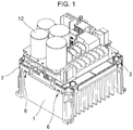
- FIG. 1 is a perspective view of an existing motor drive unit.
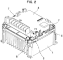
- FIG. 2 is a perspective view of an existing power PCB assembly.
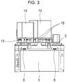
- FIG. 3 is a side view of an existing motor drive unit.
- an existing motor drive unit includes a heat sink 1, a middle base part 2, and a plurality of PCB assemblies.
- the heat sink 1 is installed on a base.
- the middle base part 2 is disposed on the heat sink 1.
- the middle base part 2 is coupled with the heat sink 1 by hooks 6.
- the area of the middle base part 2 is substantially equal to the area of the upper portion of the heat sink 1.
- the plurality of PCB assemblies is installed.
- the plurality of PCB assemblies includes a power PCB assembly 3, a condenser PCB assembly, and a control PCB assembly.
- the power PCB assembly 3 is installed on the upper portion of the middle base part 2.
- the condenser PCB assembly and the control PCB assembly are disposed on the upper portion of the power PCB assembly 3.
- the middle base part 2 disposed on the heat sink 1 is coupled by a hook 7.
- the middle base part 2 fastens and couples the plurality of PCB assemblies and isolates the heat sink 1 from the power PCB assembly 3.
- the power PCB assembly 3 is coupled on the middle base part 2 by the hooks 6 and screws.
- the heat sink 1 discharges heat generated in a module in the power PCB assembly 3.
- the condenser PCB assembly is coupled with the power PCB assembly with screw holders 10 of the power PCB assembly and bosses 11 of the middle base unit 2 and coupled with the hooks 7 of the middle base part.
- the screw holders 10 may fix the condenser PCB assembly and may allow a current to flow from the power PCB assembly 3 to condensers.
- the condensers 12 are mounted above the condenser PCB assembly.
- the heat sink has the area equal to the area of the middle base part. Therefore, the size of the heat sink is determined based on the overall size of the product, not on the optimal size for discharging heat generated in a module, such that it is difficult to reduce the size of the apparatus.
- the condensers 12 disposed on the power PCB assembly 3 are mounted only on the upper side of the board, and thus the height of the apparatus is increased with the height of the condensers 12. Therefore, there is a limit on reducing the size of the product.
- the hooks 6 in the middle base part are fastened to the heat sink 1, and thus durability is lowered and it can be easily broken by external force.
- Korean Patent Publication No. 10-2007-0053940 (published on May 28, 2007 ) discloses a flexible circuit board that prevents circuit interference between layers.
- a motor drive unit includes a base part; a middle base part disposed above the base part; a heat discharging part mounted on the base part and disposed under the middle base part to slide on the middle base part, wherein an area in which the heat discharging part is installed is smaller than an area of the middle base part; and a power PCB part disposed above the middle base part, an EMC PCB part disposed above the power PCB part with a spacing; a control PCB part coupled with a side portion of the power PCB part; and a condenser unit penetrating the middle base part to be fixed to it, wherein a lower end of the condenser unit is disposed on a side of the heat discharging part.
- the middle base part may have one or more through hole parts formed therein, and the condenser unit may be inserted and fixed to the through hole parts.
- the condenser unit may be inserted into the one or more through hole parts and fixed thereto upright.
- the through hole parts may include a through hole into which the condenser unit is inserted, and a fixture extended from the through hole downwardly to closely surround a periphery of the condenser unit.
- a pair of sliding grooves may be formed on either side of an upper portion of the heat discharging part, and a pair of sliding rails may be formed on either side of the middle base part, such that the pair of sliding rails may be inserted into the pair of the sliding grooves, respectively.
- Fixing ribs may be formed in the middle base part, and the fixing ribs fix the power PCB part upwardly with a spacing.
- Fixing projections may be formed on a side of the power PCB part, and fixing holes may be formed in the control PCB part.
- the fixing projections may be inserted into the fixing holes, respectively.
- the control PCB part may be disposed upright with respect to the base part.
- the power PCB part may have a conductive holder, and the conductive holder may fix the EMC PCB part and deliver a current input to the EMC PCB part to the power PCB part.
- the size of a heat sink can be reduced, and the size of the apparatus can be reduced by disposing condensers under a PCB such that they protrudes therefrom downwardly.
- an area in which a heat sink is installed is smaller than the area of a middle base part, and a plurality of PCB assemblies is disposed such that they surround some periphery of the heat sink and fixed thereto, thereby improving heat discharging efficiency.
- a motor drive unit can ensure durability by fixing a heat sink and condensers in different manners.
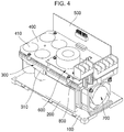
- FIG. 4 is a perspective view of a motor drive unit according to an exemplary embodiment of the present disclosure.
- FIG. 5 is a side view of the motor drive unit according to the exemplary embodiment of the present disclosure.
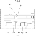
- FIG. 6 is a view showing the coupling relationship between a condenser unit and a through hole.
- the motor drive unit includes a base part 100, a middle base part 300, a heat-discharging part 200, a power PCB part 400, an EMC PCB part 600, a control PCB part 500, and a condenser unit 410.
- the middle base part 300 having a predetermined area is disposed on the base part 100.
- the heat-discharging part 200 is disposed between the middle base part 300 and the base part 100.
- the heat-discharging part 200 is a heat sink.
- the area in which the heat-discharging part 200 is installed is preferably smaller than the area of the middle base part 300.
- the area in which the heat-discharging part 200 is installed may be included in the area of the middle base part 300.
- the power PCB part 400 is disposed on the middle base part 300.
- the EMC PCB part 600 is disposed above the power PCB part 400 and spaced apart from it by a predetermined distance.
- the control PCB part 500 is disposed upright and is fixed to a side portion of the power PCB part 400.
- the lower end of the control PCB part 500 may surround the side portions of the heat-discharging part 200.
- the condenser unit 410 penetrates and is fixed to the middle base part 300, such that the lower portion is located on the side of the heat-discharging part 200.
- FIG. 7 is another side view of the motor drive unit according to the exemplary embodiment of the present disclosure.
- the heat-discharging part 200 is coupled with the middle base part 300 such that it slides thereon.
- a pair of sliding grooves 210 is formed, respectively.
- a pair of sliding rails 330 is disposed, respectively.
- the pair of sliding grooves 210 is coupled with the pair of sliding rails 330, respectively.
- the heat-discharging part 200 is coupled on the side of the middle base part 300 such that it slides thereon.
- the lower end of the heat-discharging part 200 is mounted on the base part 100.
- a fan for discharging heat 700 is installed on the side portion of the heat-discharging part 200.
- a condenser unit 410 is located on the side of the heat-discharging part 200.
- the condenser unit 410 includes condensers having the same shape, e.g., a cylinder shape.
- a through hole part 320 are formed by penetrating it, via which the condenser unit is fixed.
- the through hole part 320 includes through holes 321 into which the condenser unit 410 is inserted, and fixtures 322 extended from the through holes 321 downward to closely surround the periphery of the condenser unit 410.
- the fixtures 322 have a cylindrical shape.
- a plurality of cut-out grooves 320a is formed along the fixtures 322 upwardly such that they have a U-shape. This can mitigate impact.
- the condenser unit 410 is fixed upright by the through holes 320 formed in the middle base part 300, and the lower end is disposed adjacent to the heat discharging part.
- the power PCB part 400 is disposed above the middle base part 300 and spaced apart from it upwardly.
- a plurality of fixing ribs 311 extended upwardly is formed.
- the fixing ribs 311 penetrate the power PCB part 400 and the upper end is fastened by screw bolts 401.
- the plurality of fixing ribs 311 fixes the power PCB part 400 at several positions, such that the power PCB part 400 is spaced apart from the upper end of the middle base part 100 by the length of the fixing ribs 311.
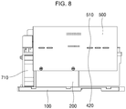
- FIG. 8 is a view showing the installation of a control PCB part according to an exemplary embodiment of the present disclosure.
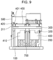
- FIG. 9 is another side view showing installation of a control PCB part according to an exemplary embodiment of the present disclosure.
- control PCB part 500 is disposed upright on the side portion of the power PCB part 400.
- a plurality of fixing projections 420 is formed, which protrudes outwardly.
- the fixing projections 420 may have a quadrangular shape.
- a plurality of fixing holes 510 is formed, in which the plurality of fixing projections 420 is inserted, respectively.
- the plurality of fixing projections 420 is inserted into the plurality of fixing holes 510, respectively, such that the control PCB part 500 is connected to the side portion of the power PCB part 400 and remains upright.
- control PCB part 500 The lower end of the control PCB part 500 is located on the side of the heat-discharging part 200, such that heat discharging is facilitated as it is adjacent to the heat-discharging part 200.
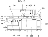
- FIG. 10 is a view showing installation of an EMC PCB part according to an exemplary embodiment of the present disclosure.
- the EMC PCB part 600 according to an exemplary embodiment of the present disclosure is disposed above the power PCB part 400.
- EMC PCB part 600 is disposed above the power PCB part 400 and spaced apart from it, it is easily exposed to the air to thereby increase the efficiency of discharging heat.
- Conductive screw holders 430 are installed in the power PCB part 400.
- the conductive screw holders 430 fix the EMC PCB part 600 such that it is spaced apart from the power PCB part 400 and delivers electric signal to the power PCB part 400.
- a brass supporter 800 may be further included.
- the brass supporter 800 may also form an earth terminal box with the heat-discharging part 200, thereby performing earth function.
- the size of a heat sink can be reduced, and the size of the apparatus can be reduced by disposing condensers such that they protrudes from the PCB downwardly.
- an area in which a heat sink is installed is smaller than the area of a middle base part, and a plurality of PCB assemblies is disposed such that they surround some periphery of the heat sink and fixed thereto, thereby improving heat discharging efficiency.
- a motor drive unit can ensure durability by fixing a heat sink and condensers in different manners.
Landscapes
- Engineering & Computer Science (AREA)
- Microelectronics & Electronic Packaging (AREA)
- Physics & Mathematics (AREA)
- Thermal Sciences (AREA)
- Power Engineering (AREA)
- Cooling Or The Like Of Electrical Apparatus (AREA)
- Motor Or Generator Cooling System (AREA)
- Control Of Electric Motors In General (AREA)
- Condensed Matter Physics & Semiconductors (AREA)
- General Physics & Mathematics (AREA)
- Computer Hardware Design (AREA)
- Inverter Devices (AREA)
Applications Claiming Priority (1)
| Application Number | Priority Date | Filing Date | Title |
|---|---|---|---|
| KR1020160021750A KR101835954B1 (ko) | 2016-02-24 | 2016-02-24 | 전동기 구동 장치 |
Publications (1)
| Publication Number | Publication Date |
|---|---|
| EP3211981A1 true EP3211981A1 (fr) | 2017-08-30 |
Family
ID=57909473
Family Applications (1)
| Application Number | Title | Priority Date | Filing Date |
|---|---|---|---|
| EP17153014.0A Withdrawn EP3211981A1 (fr) | 2016-02-24 | 2017-01-25 | Unité d'entraînement de moteur |
Country Status (5)
| Country | Link |
|---|---|
| US (1) | US9936600B2 (fr) |
| EP (1) | EP3211981A1 (fr) |
| JP (1) | JP6337162B2 (fr) |
| KR (1) | KR101835954B1 (fr) |
| CN (1) | CN107124848B (fr) |
Cited By (1)
| Publication number | Priority date | Publication date | Assignee | Title |
|---|---|---|---|---|
| EP3562288A1 (fr) * | 2018-04-26 | 2019-10-30 | LSIS Co., Ltd. | Dispositif de commande de moteur |
Families Citing this family (3)
| Publication number | Priority date | Publication date | Assignee | Title |
|---|---|---|---|---|
| RU2172349C2 (ru) * | 1999-08-19 | 2001-08-20 | Криночкин Эдуард Викторович | Способ производства стали |
| KR102082207B1 (ko) * | 2018-05-02 | 2020-02-27 | 엘에스산전 주식회사 | 전동기 구동장치 |
| USD1025049S1 (en) * | 2021-05-27 | 2024-04-30 | Siemens Aktiengesellschaft | Computer |
Citations (10)
| Publication number | Priority date | Publication date | Assignee | Title |
|---|---|---|---|---|
| JP2002016385A (ja) * | 2000-06-26 | 2002-01-18 | Nippon Yusoki Co Ltd | 発熱部品の放熱装置 |
| US6989616B2 (en) * | 2002-06-13 | 2006-01-24 | Mitsuba Corporation | Motor |
| KR20070053940A (ko) | 2005-11-22 | 2007-05-28 | 엘지전자 주식회사 | 층간 회로간섭이 방지된 연성회로기판 |
| US20080112132A1 (en) * | 2006-11-09 | 2008-05-15 | Ralf Ehler | Electric Power Module |
| US20090268405A1 (en) * | 2008-04-25 | 2009-10-29 | Rockwell Automation Technologies, Inc. | Power electronic module cooling system and method |
| US20100046174A1 (en) * | 2008-08-20 | 2010-02-25 | Hong Fu Jin Precision Industry (Shenzhen) Co.,Ltd. | Printed circuit board fixing structure and electronic device with same |
| JP2010104146A (ja) * | 2008-10-23 | 2010-05-06 | Mitsubishi Electric Corp | 電力変換装置 |
| DE102012103217B3 (de) * | 2012-04-13 | 2013-08-22 | Elka-Elektronik Gmbh | Steuerungsgerät für ein Gebäudeinstallationssystem |
| US20140305614A1 (en) * | 2013-04-10 | 2014-10-16 | Wistron Corporation | Heat dissipation device |
| KR101466032B1 (ko) * | 2013-08-02 | 2014-11-28 | 엘에스산전 주식회사 | 인버터 장치 |
Family Cites Families (42)
| Publication number | Priority date | Publication date | Assignee | Title |
|---|---|---|---|---|
| JPH084260B2 (ja) | 1987-12-17 | 1996-01-17 | 富士通株式会社 | クロック選択回路 |
| US5257180A (en) | 1991-04-22 | 1993-10-26 | Mitsubishi Denki Kabushiki Kaisha | Controlling system for parallel operation of AC output inverters with restrained cross currents |
| CN2438268Y (zh) * | 2000-06-27 | 2001-07-04 | 环隆电气股份有限公司 | 无刷马达控制器组合装置 |
| KR20040103001A (ko) | 2003-05-30 | 2004-12-08 | 테크노밸리(주) | 전동기 보호기 |
| KR20060054393A (ko) * | 2003-08-01 | 2006-05-22 | 지멘스 악티엔게젤샤프트 | 전자 유닛 및 전자 유닛의 제조 방법 |
| JP2005064046A (ja) * | 2003-08-13 | 2005-03-10 | Fuji Electric Fa Components & Systems Co Ltd | ファン実装構造 |
| DK200301577A (da) * | 2003-10-27 | 2005-04-28 | Danfoss Silicon Power Gmbh | Flowfordelingsenhed og köleenhed |
| US7133287B2 (en) * | 2004-03-31 | 2006-11-07 | Intel Corporation | ATCA integrated heatsink and core power distribution mechanism |
| JP4265558B2 (ja) | 2005-03-30 | 2009-05-20 | 日立アプライアンス株式会社 | 冷凍装置及びそれに用いられるインバータ装置 |
| US7324341B2 (en) * | 2005-09-22 | 2008-01-29 | Delphi Technologies, Inc. | Electronics assembly and heat pipe device |
| ES2655254T3 (es) | 2006-01-16 | 2018-02-19 | Mitsubishi Electric Corporation | Circuito de control de motor y unidad exterior de aparato de aire acondicionado |
| US20070165376A1 (en) * | 2006-01-17 | 2007-07-19 | Norbert Bones | Three phase inverter power stage and assembly |
| US7551439B2 (en) * | 2006-03-28 | 2009-06-23 | Delphi Technologies, Inc. | Fluid cooled electronic assembly |
| WO2008029637A1 (fr) * | 2006-09-06 | 2008-03-13 | Kabushiki Kaisha Yaskawa Denki | Dispositif de commande de moteur |
| CN101513152B (zh) * | 2006-09-07 | 2012-02-01 | 株式会社安川电机 | 马达控制器 |
| JP4580997B2 (ja) * | 2008-03-11 | 2010-11-17 | 日立オートモティブシステムズ株式会社 | 電力変換装置 |
| KR200457636Y1 (ko) | 2010-01-29 | 2011-12-28 | 엘에스산전 주식회사 | 전동기 제어 장치 |
| US8203839B2 (en) * | 2010-03-10 | 2012-06-19 | Toyota Motor Engineering & Manufacturing North America, Inc. | Cooling devices, power modules, and vehicles incorporating the same |
| JP2011192809A (ja) * | 2010-03-15 | 2011-09-29 | Omron Corp | パワーコンディショナー装置およびこの装置に使用するモジュール基板構造 |
| CN102200814A (zh) * | 2010-03-24 | 2011-09-28 | 鸿富锦精密工业(深圳)有限公司 | 机箱散热装置 |
| US8243451B2 (en) * | 2010-06-08 | 2012-08-14 | Toyota Motor Engineering & Manufacturing North America, Inc. | Cooling member for heat containing device |
| JP5249365B2 (ja) * | 2011-01-26 | 2013-07-31 | 三菱電機株式会社 | 電力変換装置 |
| US9030822B2 (en) * | 2011-08-15 | 2015-05-12 | Lear Corporation | Power module cooling system |
| JP2013070028A (ja) | 2011-09-07 | 2013-04-18 | Hitachi Automotive Systems Ltd | 電子制御装置 |
| JP5566356B2 (ja) * | 2011-09-15 | 2014-08-06 | 日立オートモティブシステムズ株式会社 | モータ駆動装置 |
| JP5893312B2 (ja) | 2011-09-27 | 2016-03-23 | 株式会社ケーヒン | 半導体制御装置 |
| CN103023279B (zh) * | 2011-09-27 | 2015-05-13 | 株式会社京浜 | 半导体控制装置 |
| JP2013103535A (ja) | 2011-11-10 | 2013-05-30 | Honda Elesys Co Ltd | 電動パワーステアリング用電子制御ユニット |
| EP2645040B1 (fr) * | 2012-03-28 | 2017-06-21 | ABB Research Ltd. | Échangeur de chaleur pour convertisseurs de traction |
| KR101375956B1 (ko) * | 2012-07-05 | 2014-03-18 | 엘에스산전 주식회사 | 자동차용 전장부품 박스 |
| JP5738817B2 (ja) * | 2012-09-14 | 2015-06-24 | 日立オートモティブシステムズ株式会社 | 電力変換装置 |
| US9295184B2 (en) * | 2012-12-14 | 2016-03-22 | GM Global Technology Operations LLC | Scalable and modular approach for power electronic building block design in automotive applications |
| WO2014106051A1 (fr) * | 2012-12-30 | 2014-07-03 | General Electric Company | Appareil et procédé de dissipation de chaleur pour module de dispositif de semi-conducteur de puissance |
| JP5657716B2 (ja) * | 2013-01-15 | 2015-01-21 | ファナック株式会社 | 放熱器を備えたモータ駆動装置 |
| JP6195453B2 (ja) | 2013-02-20 | 2017-09-13 | 三菱重工オートモーティブサーマルシステムズ株式会社 | インバータ一体型電動圧縮機 |
| JP6163835B2 (ja) * | 2013-04-01 | 2017-07-19 | 富士電機株式会社 | 冷却フィンおよび該冷却フィンを具備する電力変換装置 |
| US9247679B2 (en) * | 2013-05-24 | 2016-01-26 | Toyota Motor Engineering & Manufacturing North America, Inc. | Jet impingement coolers and power electronics modules comprising the same |
| US9414520B2 (en) * | 2013-05-28 | 2016-08-09 | Hamilton Sundstrand Corporation | Immersion cooled motor controller |
| US20150170989A1 (en) * | 2013-12-16 | 2015-06-18 | Hemanth K. Dhavaleswarapu | Three-dimensional (3d) integrated heat spreader for multichip packages |
| US9362040B2 (en) * | 2014-05-15 | 2016-06-07 | Lear Corporation | Coldplate with integrated electrical components for cooling thereof |
| CN105207650B (zh) * | 2015-09-15 | 2018-10-19 | 重庆大学 | 一种基于串联层叠Blumlein微带传输线高压纳秒发生器 |
| CN105207540A (zh) * | 2015-09-29 | 2015-12-30 | 东风商用车有限公司 | 一种电动车辆开关磁阻电机控制器内部布置结构 |
-
2016
- 2016-02-24 KR KR1020160021750A patent/KR101835954B1/ko active Active
-
2017
- 2017-01-20 US US15/411,809 patent/US9936600B2/en active Active
- 2017-01-23 JP JP2017009677A patent/JP6337162B2/ja active Active
- 2017-01-25 EP EP17153014.0A patent/EP3211981A1/fr not_active Withdrawn
- 2017-01-25 CN CN201710060683.3A patent/CN107124848B/zh active Active
Patent Citations (10)
| Publication number | Priority date | Publication date | Assignee | Title |
|---|---|---|---|---|
| JP2002016385A (ja) * | 2000-06-26 | 2002-01-18 | Nippon Yusoki Co Ltd | 発熱部品の放熱装置 |
| US6989616B2 (en) * | 2002-06-13 | 2006-01-24 | Mitsuba Corporation | Motor |
| KR20070053940A (ko) | 2005-11-22 | 2007-05-28 | 엘지전자 주식회사 | 층간 회로간섭이 방지된 연성회로기판 |
| US20080112132A1 (en) * | 2006-11-09 | 2008-05-15 | Ralf Ehler | Electric Power Module |
| US20090268405A1 (en) * | 2008-04-25 | 2009-10-29 | Rockwell Automation Technologies, Inc. | Power electronic module cooling system and method |
| US20100046174A1 (en) * | 2008-08-20 | 2010-02-25 | Hong Fu Jin Precision Industry (Shenzhen) Co.,Ltd. | Printed circuit board fixing structure and electronic device with same |
| JP2010104146A (ja) * | 2008-10-23 | 2010-05-06 | Mitsubishi Electric Corp | 電力変換装置 |
| DE102012103217B3 (de) * | 2012-04-13 | 2013-08-22 | Elka-Elektronik Gmbh | Steuerungsgerät für ein Gebäudeinstallationssystem |
| US20140305614A1 (en) * | 2013-04-10 | 2014-10-16 | Wistron Corporation | Heat dissipation device |
| KR101466032B1 (ko) * | 2013-08-02 | 2014-11-28 | 엘에스산전 주식회사 | 인버터 장치 |
Cited By (2)
| Publication number | Priority date | Publication date | Assignee | Title |
|---|---|---|---|---|
| EP3562288A1 (fr) * | 2018-04-26 | 2019-10-30 | LSIS Co., Ltd. | Dispositif de commande de moteur |
| US10804662B2 (en) | 2018-04-26 | 2020-10-13 | Lsis Co., Ltd. | Device for driving motor |
Also Published As
| Publication number | Publication date |
|---|---|
| CN107124848A (zh) | 2017-09-01 |
| KR20170099549A (ko) | 2017-09-01 |
| KR101835954B1 (ko) | 2018-04-19 |
| JP6337162B2 (ja) | 2018-06-06 |
| CN107124848B (zh) | 2020-02-07 |
| US20170245387A1 (en) | 2017-08-24 |
| JP2017153347A (ja) | 2017-08-31 |
| US9936600B2 (en) | 2018-04-03 |
Similar Documents
| Publication | Publication Date | Title |
|---|---|---|
| US9936600B2 (en) | Motor drive unit | |
| JP6173763B2 (ja) | インバータ一体型電動圧縮機 | |
| JP2010140657A (ja) | 誘導加熱調理器 | |
| EP2909695A1 (fr) | Dispositif électronique avec combinaison radiateur / dispositif soufflant ou ventilateur possédant une conduite d'air | |
| JP6614793B2 (ja) | シールドを有する電気システム | |
| CN208113061U (zh) | 一种新型电路板 | |
| CN202514190U (zh) | 一种带有pcb固定装置的外壳 | |
| KR20110038888A (ko) | 방열구조의 커버를 구비하는 인버터 | |
| CN105636421B (zh) | 家用电器及减少干扰电压的装置 | |
| CN210671002U (zh) | 一种电压调节器的新型散热器结构 | |
| CN209945364U (zh) | 核心板与wifi天线一体式安装及散热装置 | |
| CN202111985U (zh) | Emi遮罩的固定片 | |
| CN102522188B (zh) | 一种电感线端子固定座 | |
| CN210848736U (zh) | 智能电容储能螺柱焊机的电容安装结构 | |
| CN106710873A (zh) | 一种电容器用安装件 | |
| CN216357480U (zh) | 一种具有抗电磁干扰的pcb线路板 | |
| CN218570718U (zh) | 一种散热型电路板组件 | |
| CN207031784U (zh) | 用于洗衣机的电路板组件及洗衣机 | |
| CN205792185U (zh) | 性能可靠的变频器 | |
| CN215552985U (zh) | 一种控制板支架总成及控制器总成 | |
| CN202551569U (zh) | 用于印刷电路板的间隔柱 | |
| CN220489289U (zh) | 一种空调外机 | |
| CN218243955U (zh) | 一种可承载大电流的印制线路板 | |
| CN218602963U (zh) | 一种ups馈线柜 | |
| CN219371691U (zh) | 一种配电箱内配电底板的固定结构 |
Legal Events
| Date | Code | Title | Description |
|---|---|---|---|
| PUAI | Public reference made under article 153(3) epc to a published international application that has entered the european phase |
Free format text: ORIGINAL CODE: 0009012 |
|
| STAA | Information on the status of an ep patent application or granted ep patent |
Free format text: STATUS: THE APPLICATION HAS BEEN PUBLISHED |
|
| AK | Designated contracting states |
Kind code of ref document: A1 Designated state(s): AL AT BE BG CH CY CZ DE DK EE ES FI FR GB GR HR HU IE IS IT LI LT LU LV MC MK MT NL NO PL PT RO RS SE SI SK SM TR |
|
| AX | Request for extension of the european patent |
Extension state: BA ME |
|
| STAA | Information on the status of an ep patent application or granted ep patent |
Free format text: STATUS: REQUEST FOR EXAMINATION WAS MADE |
|
| 17P | Request for examination filed |
Effective date: 20180226 |
|
| RBV | Designated contracting states (corrected) |
Designated state(s): AL AT BE BG CH CY CZ DE DK EE ES FI FR GB GR HR HU IE IS IT LI LT LU LV MC MK MT NL NO PL PT RO RS SE SI SK SM TR |
|
| STAA | Information on the status of an ep patent application or granted ep patent |
Free format text: STATUS: EXAMINATION IS IN PROGRESS |
|
| 17Q | First examination report despatched |
Effective date: 20211129 |
|
| STAA | Information on the status of an ep patent application or granted ep patent |
Free format text: STATUS: THE APPLICATION HAS BEEN WITHDRAWN |
|
| 18W | Application withdrawn |
Effective date: 20230811 |