EP3211919B1 - Elektromechanischer wandler - Google Patents
Elektromechanischer wandler Download PDFInfo
- Publication number
- EP3211919B1 EP3211919B1 EP17157361.1A EP17157361A EP3211919B1 EP 3211919 B1 EP3211919 B1 EP 3211919B1 EP 17157361 A EP17157361 A EP 17157361A EP 3211919 B1 EP3211919 B1 EP 3211919B1
- Authority
- EP
- European Patent Office
- Prior art keywords
- armature
- electromechanical transducer
- displacement
- magnets
- magnetic
- Prior art date
- Legal status (The legal status is an assumption and is not a legal conclusion. Google has not performed a legal analysis and makes no representation as to the accuracy of the status listed.)
- Active
Links
Images


Classifications
-
- H—ELECTRICITY
- H02—GENERATION; CONVERSION OR DISTRIBUTION OF ELECTRIC POWER
- H02K—DYNAMO-ELECTRIC MACHINES
- H02K33/00—Motors with reciprocating, oscillating or vibrating magnet, armature or coil system
- H02K33/02—Motors with reciprocating, oscillating or vibrating magnet, armature or coil system with armatures moved one way by energisation of a single coil system and returned by mechanical force, e.g. by springs
-
- H—ELECTRICITY
- H04—ELECTRIC COMMUNICATION TECHNIQUE
- H04R—LOUDSPEAKERS, MICROPHONES, GRAMOPHONE PICK-UPS OR LIKE ACOUSTIC ELECTROMECHANICAL TRANSDUCERS; ELECTRIC HEARING AIDS; PUBLIC ADDRESS SYSTEMS
- H04R11/00—Transducers of moving-armature or moving-core type
- H04R11/02—Loudspeakers
-
- H—ELECTRICITY
- H04—ELECTRIC COMMUNICATION TECHNIQUE
- H04R—LOUDSPEAKERS, MICROPHONES, GRAMOPHONE PICK-UPS OR LIKE ACOUSTIC ELECTROMECHANICAL TRANSDUCERS; ELECTRIC HEARING AIDS; PUBLIC ADDRESS SYSTEMS
- H04R25/00—Electric hearing aids
Definitions
- the present invention relates to an electromechanical transducer that transduces an electric signal into mechanical vibration, and particularly relates to an electromechanical transducer that comprises a driving unit including an armature, a yoke, a coil, magnets and any other member.
- An electromechanical transducer or an electroacoustic transducer used in a hearing aid or the like is provided with a driving unit including an armature, a yoke, a coil and magnets, etc., and is configured to drive the armature in response to an electric signal supplied to the coil so that relative vibration between the armature and other members is transduced into mechanical vibration or sound.
- the magnetic forces act on the armature from the upper and lower magnets, and the armature is relatively displaced to a position where the magnetic forces are balanced with restoring force.
- the restoring force is given by elastic force of the armature itself in the case of the Patent Reference 1 while it is given by elastic force of the spring members in the case of the Patent Reference 2.
- the armature is attracted to the upper or lower magnet by the action of the magnetic force.
- the armature is returned to the balanced position. That is, in order to prevent the armature from being attracted to the magnets, it needs to be designed so that the restoring force toward the balanced position is larger than the magnetic force (attraction) toward the magnets even if the armature is positioned at any position within a range of displacement.
- EP 2 897 380 A1 discloses an electromechanical transducer comprising a structural unit, an armature, and two elastic units.
- CN 103428618 A is directed to an armature device used for moving iron-type loud speaker or receiver, comprising a vibrating tongue piece, support pins and a connecting part.
- US 2015/0010199 A1 describes a balanced armature transducer being formed with components housed within a frame.
- WO 2010/025351 A2 discloses methods and apparatus for reduced distortion balanced armature devices.
- the electromechanical transducer In order to realize an electromechanical transducer of small size and high output power, it is desirable to increase a driving force of the electromechanical transducer as much as possible. For this purpose, it is required to increase a ratio of the magnetic force relative to the amount of displacement of the armature (negative stiffness) in the vicinity of the balanced position so that the ratio gets closer to stiffness of the restoring force (elastic force) of the armature.
- the restoring force is required to be larger than the magnetic force within the range of displacement of the armature, as described above, and given that the magnetic force changes non-linearly relative to the displacement of the armature (see Fig.
- an electromechanical transducer transducing an electric signal into mechanical vibration, as defined by claim 1, the electromechanical transducer comprising: a structural unit in which at least one pair of magnets, a yoke conducting magnetic flux generated by the magnets, and a coil supplied with the electric signal are integrally arranged; an armature including an inner portion disposed to pass through an internal space of the structural unit and first and second outer portions protruding on both sides in a first direction from the inner portion, the armature constituting a magnetic circuit with the structural unit via two regions through which components of the magnetic flux flow in directions opposite to each other in the inner portion and being displaced in a displacement direction based on a magnetic force of the magnetic circuit; a first elastic unit giving a restoring force to the first outer portion in response to displacement of the armature, the first elastic unit being held between the first outer portion and the structural unit; and a second elastic unit giving a restoring force to the second outer portion in response to displacement of the armature, the second elastic unit being held
- the armature which is positioned at a balanced position when no current flows in the coil, is displaced relative to the structural unit due to the magnetic force applied to the inner portion when the current flows in the coil, and at this point, each of the first and second elastic units gives the restoring force acting on the armature.
- each of the first and second elastic units gives the restoring force acting on the armature.
- the armature of the invention can be formed in various shapes as long as the above condition of the cross-sectional area is satisfied.
- a width of the armature in a second direction perpendicular to the first direction and the displacement direction may be smaller at the predetermined position than at the two regions.
- the armature is preferably a plate-like member having a constant thickness in the displacement direction.
- the armature having a shape of partially narrow width can be processed relatively easy, and it is possible to reduce influence on shock resistance in comparison with thinning the armature.
- the magnetic circuit can be configured using at least one pair of magnets in the two regions of the armature.
- Each of the first and second elastic units may be a pair of elastic members being symmetrically arranged in the displacement direction via the armature.
- the pair of elastic members may be a pair of spring members being symmetrically arranged in the displacement direction via the armature.
- the present invention by partially reducing the cross sectional area between the two regions of the armature, it is possible to saturate the magnetic flux flowing in the first direction in the armature within a range of displacement thereof. Therefore, it is possible to realize an electromechanical transducer capable of obtaining a large driving force relative to the input power while maintaining excellent magnetic characteristics and reliability.
- FIG. 1 is a perspective view showing a structure in which a housing 10 that contains the entire electromechanical transducer of the embodiment is detached.
- Figs. 2 to 4 are views of the electromechanical transducer of the embodiment as viewed in directions perpendicular to one another, in which an X direction, a Y direction and a Z direction are indicated by arrows, respectively, for purposes of illustration.
- Fig. 1 is a perspective view showing a structure in which a housing 10 that contains the entire electromechanical transducer of the embodiment is detached.
- Figs. 2 to 4 are views of the electromechanical transducer of
- FIG. 2 is a top view (partially cutaway end view in which later-mentioned housing member 10b, a part of a yoke 13 and a magnet 16 are cut away) of the electromechanical transducer of the embodiment as viewed from one side in the Z direction (from the top side of Fig. 1 )
- Fig. 3 is a cross-sectional view of the electromechanical transducer of the embodiment along an A-A cross section shown in Fig. 2
- Fig. 4 is a cross-sectional view of the electromechanical transducer of the embodiment along a B-B cross section shown in Fig. 2 .
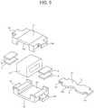
- Fig. 5 is an exploded perspective view of a later-mentioned magnetic circuit portion in the electromechanical transducer of the embodiment.
- the electromechanical transducer of the embodiment does not have directionality of vertical and horizontal directions, the following descriptions may include expressions using the vertical and horizontal directions in accordance with directions (X, Y and Z) in the plane when viewed in the figures for the purpose of
- the housing 10 that houses the entire electromechanical transducer of the embodiment has a structure formed by joining a lower housing member 10a and an upper housing member 10b that are vertically symmetrical to each other.
- a later-mentioned driving unit 11 of the electromechanical transducer is contained in the housing 10. It is preferable to use light material to form the housing 10 within a strength range capable of supporting the driving unit 11, for example, plastic material or metal material such as stainless steel is used.
- four stoppers S for suppressing excessive movement of the driving unit 11 in the Y direction within the range of movement are formed inside each of the lower and upper housing members 10a and 10b.
- the entire electromechanical transducer is actually covered by the housing 10 having the structure shown in Fig. 1 , but Figs. 2 to 4 show internal structures that are viewed when the housing 10 is partially removed.
- the driving unit 11 includes a pair of yokes 12 and 13, a coil 14, four magnets 15, 16, 17 and 18, an armature 19, four armature reinforcing plates P1, and four spring members 20, 21, 22 and 23.
- the yokes 12 and 13, the coil 14, the four magnets 15 to 18 function as an integrally arranged structural unit of the invention, and the armature 19 penetrating an internal space of this structural unit is disposed so as to be movable to the driving unit 11 via the spring members 20 to 23.
- a pair of leads for supplying an electric signal is extended from the coil 14 and is electrically connected to a pair of electric terminals provided at one end outside the housing 10, which are omitted in Figs. 1 to 4 .
- the lower yoke 12 and the upper yoke 13 are integrally fixed to each other, for example by welding, in a state of facing each other in the Z direction.
- inwardly facing concave portions 12a and 13a are formed in central portions of the respective yokes 12 and 13, and the coil 14 having a through hole is sandwiched between the concave portions 12a and 13a of the upper and lower yokes 12 and 13.
- the coil 14 in which both ends of its through hole are open in the X direction is positioned at the center between the yokes 12 and 13 and is fixed to inner surfaces of the yokes 12 and 13 by adhesive.
- soft magnetic material such as permalloy (45% Ni) can be used to form the yokes 12 and 13.
- spring member attaching portions 12b, 12c, 13b and 13c protruding on both sides in the X direction of the yokes 12 and 13, respectively.
- the spring members 20 and 22 abut the spring member attaching portions 12b and 12c of the yoke 12 at sides facing the armature 19, respectively
- the spring members 21 and 23 abut the spring member attaching portions 13b and 13c of the yoke 13 at sides facing the armature 19, respectively.
- cut away portions are formed on both sides in the Y direction of each of the four spring member attaching portions 12b, 12c, 13b and 13c, and a later-mentioned yoke attaching portion 21c ( Fig.
- each spring members 20 to 23 is partially engages the cut away portions. That is, the four spring member attaching portions 12b, 12c, 13b and 13c and the spring members 20 to 23 are not fixed to each other by welding or adhesive. A specific structure of the spring members 20 to 23 will be described later.
- the magnets 15 to 18 are arranged symmetrically on both sides in the X direction on insides of the yokes 12 and 13. That is, a pair of magnets 15 to 16 are adhesively bonded to one opposed end surfaces of the yokes 12 and 13 in the X direction and faces each other with an appropriate distance. Similarly, a pair of magnets 17 to 18 are adhesively bonded to the other opposed end surfaces of the yokes 12 and 13 in the X direction and faces each other with an appropriate distance.
- the armature 19 is a long plate-like member extending in the X direction and is disposed so as to pass through a space between the pair of magnets 15 to 16, the through hole of the coil 14, and a space between the pair of magnets 17 to 18. As shown in Fig. 5 , the armature 19 includes an inner portion 19a positioned in a space facing the yokes 12 and 13 (the internal space of the structural unit) and outer portions 19b and 19c protruding from both sides of the inner portion 19a.
- a pair of circular arc-shaped concave portions C are formed at the center in the X direction in the inner portion 19a of the armature 19, and a region in which no concave portion C is formed has the same width in the Y direction as of the magnets 15 to 18.
- the concave portions C have a function to saturate the magnetic flux flowing in the X direction of the armature 19 by partially reducing the width in the Y direction of the armature 19, which will be described in detail below.
- the outer portions 19b and 19c of the armature 19 are formed in rectangular portions having a width narrower than the inner portion 19a in the Y direction that are partially cut away.
- the soft magnetic material such as permalloy (45% Ni) can be used to form the armature 19 in the same manner as the yokes 12 and 13.
- Each of the armature reinforcing plates P1 has a rectangular shape having the same width as the cut away portions of the outer portions 19b and 19c in the Y direction, as shown in Fig. 2 , and thus serves to secure thickness of portions of the armature 19 to which the spring members 20 to 23 are attached.
- the thickness of the armature 19 can be sufficiently secured in consideration of designs of the magnetic circuit and the spring members 20 to 23, there is no need to provide the armature reinforcing plates P1.
- the armature 19 and the magnets 15 to 18 there are formed parallel interspaces between the armature 19 and the magnets 15 to 18 above and below the armature 19 (both sides in the Z direction), and the respective interspaces form air gaps G1, G2, G3 and G4 ( Fig. 7 ). Since the four magnets 15 to 18 have the same shape as one another and are symmetrically arranged in the X and Y directions, the four air gaps G1 to G4 also have the same shape as one another.
- the interspaces (thickness) of the air gaps G1 to G4 are appropriately formed so that the armature 19 does not contact the coil 14 and the magnets 15 to 18 when the armature 19 is displaced in the Z direction within a normal working range.
- each of the outer portions 19b and 19c of the armature 19 is sandwiched between the housing members 10a and 10b via the armature reinforcing plates P1 and is fixed by adhesive or the like.
- the housing 10 is formed so as not to contact the driving unit 11 other than both ends of the armature 19.
- the above connection portions between the armature 19 and the housing 10 need to have sufficient stiffness such that vibration generated in the driving unit 11 is reliably transmitted to the housing 10.
- each shape of the outer portions 19b and 19c on both sides of the armature 19 overlaps a shape of each opposed portion of the spring member attaching portions 12b, 13b, 12c and 13c of the yokes 12 and 13 in the Z direction.
- Each of the four the spring members 20 to 23 is a leaf spring formed by bending a plate-like member, a pair of the spring members 20 and 21 (the first elastic unit of the invention) are attached to one outer portion 19b of the armature 19, and a pair of the spring members 22 and 23 (the second elastic unit of the invention) are attached to the other outer portion 19c of the armature 19.
- the role of the spring members 20 to 23 is that, when the armature 19 is relatively displaced in the magnetic circuit relative to the structural unit, the spring members 20 to 23 give a restoring force to the armature 19, which is proportional to the amount of displacement of the armature 19. As shown in Fig.
- the lower spring member 20 (22) and the upper spring member 21 (23) are symmetrically arranged in the Z direction in a state of sandwiching the armature 19 from both sides in the Z direction.
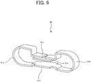
- a structure of each of the spring members 20 to 23 will be described with reference to a perspective view shown in Fig. 6 .
- Fig. 6 representatively shows a structure of the spring member 21, other spring members 20, 22 and 23 have the same structure.
- the spring member 21 includes two curved portions 21a and 21b on both sides in the Y direction, a yoke attaching portion 21c and an armature attaching portion 21d that serve as inwardly facing concave portions vertically opposed to each other at the center, and spring member reinforcing plate 21e.
- the spring members 20, 22 and 23 (not shown in Fig.
- the spring member reinforcing plate 21e is welded to an inner surface of the yoke attaching portion 21c (an inner side of the spring member 21). Both ends of the plate-like member used for forming the spring member 21 are connected via the spring member reinforcing plate 21e at the yoke attaching portion 21c so as to form a continuous ring shape. If no cut section is formed in the spring member 21, there is no need to provide the spring reinforcing plate 21e.
- the spring member 21 functions as the elastic member of the invention.
- the shape of the spring member 21 shown in Fig. 6 is such that, as shown in Fig. 4 , the concave shape of the yoke attaching portion 21c engages the shape of the spring member attaching portion 13b of the yoke 13, and the concave shape of the armature attaching portion 21d engages the shapes of the armature 19 and the armature reinforcing plate P1.
- these engaging portions are not fixed by welding or adhesive, when the spring member 21 is mounted in the driving unit 11, it is possible to restrict movements of the spring member 21 in the X and Y directions by the respective concave shapes.
- the spring member 21 is stably held and contacts the spring member attaching portion 13b of the yoke 13 and the armature reinforcing plate P1, respectively.
- the spring member 20 is held in a symmetrical arrangement in the Z direction relative to the spring member 21. Further, as shown in Fig. 4 , a pair of spring members 20, 21 (22, 23) are slightly compressed in the Z direction so that a pressing force thereof holds the armature 19 at a balanced position.
- the spring members 20 to 23 of the embodiment it is necessary to determine the shape, material and thickness of the leaf spring, curvature of the curved portions 21a and 21b and the like, so as to obtain a spring constant in accordance with the restoring force that should be given to the armature 19.
- non-magnetic material such as SUS for spring can be used to form the spring members 20 to 23.
- the thickness of the spring members 20 to 23 can be set to, for example, about 0.1 mm.
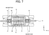
- Fig. 7 is a view schematically showing a part constituting the magnetic circuit including the yokes 12 and 13, the coil 14, the magnets 15 to 18 and the armature 19 in the cross-sectional view shown in Fig. 3 .
- the armature reinforcing plates P1 fixed to the armature 19 are omitted, and other components not included in the magnetic circuit are also omitted.
- the pair of magnets 15 and 16 and the pair of magnets 17 and 18 that are oppositely arranged in the Z direction via the coil 14 have been magnetized in directions reverse to each other.
- FIG. 7 are magnetized downward, and the magnets 17 and 18 on the left of Fig. 7 are magnetized upward.
- a magnetic flux B1 indicated by solid arrows is generated in the yokes 12 and 13 and the armature 19 by the magnets 15 to 18 magnetized in this manner.
- a magnetic flux having a direction according to the direction of the current is generated in the portion surrounded by the coil 14 in the armature 19.
- Fig. 7 shows a state where a magnetic flux B2 indicated by a dashed arrow is generated in the armature 19 due to the coil current.
- the generation of the magnetic flux B2 causes magnetic fluxes of the lower air gaps G1 and G3 to increase, respectively, and causes magnetic fluxes of the upper air gaps G2 and G4 to decrease, respectively.
- the armature 19 is displaced downward by being applied with the downward magnetic force.
- a relative vibration between this structural unit and the armature 19 will be considered hereinafter.
- a driving force is generated in response to the current flowing when an electric signal is applied to the coil 14, and this driving force causes the above relative vibration. Since the both ends of the armature 19 are fixed to the housing 10 with sufficient stiffness, the driving force generated between the armature 19 and the structural unit is transmitted to the housing 10 via the armature 19 so as to vibrate the housing 10.
- the electromechanical transducer of the embodiment is configured to generate mechanical vibration corresponding to the electric signal applied from outside.
- Fig. 8 shows an example of a calculation result of the magnetic force and negative stiffness relative to the amount of displacement of the armature 19 when using the conventional type armature (for example, the armature 19 described in the Patent Reference 2) on which the concave portions C are not formed, which is shown as a comparison example to be compared with the electromechanical transducer of the embodiment.
- the magnetic force Fm does not linearly change with the amount of displacement and includes high-level terms thereof, the negative stiffness Sm corresponding to a slope of the magnetic force Fm increases with x in Fig. 8 .
- the restoring force acting on the armature 19 by the spring members 20 to 23 must be always larger than the magnetic force Fm.
- the spring constant (stiffness) of the spring members 20 to 23 it is necessary to set the spring constant (stiffness) of the spring members 20 to 23 to be larger than the negative stiffness Sm at any position in the range of displacement of the armature 19.
- Sm max the maximum value of the negative stiffness Sm is represented as Sm max
- a stiffness Se of the spring members 20 to 23 needs to be larger than this value.
- ⁇ S Sm max ⁇ Sm 0
- the maximum value of the sensitivity of the electromechanical transducer is to be in proportion to a reciprocal of the difference ⁇ S in the formula (1) .
- the driving force of the electromechanical transducer is equal to a product of the amount of displacement of the armature 19 and the stiffness Se of the spring members 20 to 23.
- the stiffness Se of the spring members 20 to 23 needs to be equal to the maximum value Sm max of the negative stiffness within the range of displacement of the armature 19.
- Sm max the maximum value of the driving force relative to the input power
- the magnitude of the driving force relative to the input power can be set to an extremely large value.
- Sm(0)/Sm max is approximately 0.64
- Sm max / ⁇ S becomes approximately 2.8
- Sm(0) /Sm max can be greater than 0.9
- Sm max / ⁇ S becomes greater than 10 so that the driving force can be increased more than three times.
- Fig. 9 shows an example of a calculation result under the same conditions as in Fig. 8 in a case using the armature 19 in the electromechanical transducer of the embodiment.
- the meanings of the horizontal and vertical axes and respective parameters are the same as those described in Fig. 8 .
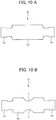
- Figs. 10A and 10B show and compare shapes of the armature 19 in a planar view corresponding to the calculation results shown in Figs. 8 and 9 .
- Fig. 10A shows a plane view of the armature 19 of the conventional type in an X-Y plane corresponding to Fig. 8
- Fig. 10B shows a plane view of the armature 19 of the embodiment in the X-Y plane corresponding to Fig. 9 .
- the inner portion 19a of the armature 19 in Fig. 10A has a constant width in the Y direction, while the width in the Y direction in Fig. 10B is shortened at the concave portions C so that the inner portion 19a has its narrowest part at the center. Since, the thickness of the armature 19 in the Z direction is common in Figs. 10A and 10B , a cross-sectional area at the center of the armature 19 in Fig. 10B is smaller than that in Fig. 10A by a ratio of the respective widths at the center.
- a structural feature of the embodiment is to form the concave portions C on the armature 19 so as to reduce the cross-sectional area A, thereby magnetically saturating the armature 19 within the range of displacement.
- the magnetic force Fm and the negative stiffness Sm vary in approximately the same manner as in Fig. 8 in the vicinity of the balanced position of the armature 19, and however, when the amount of displacement of the armature 19 becomes large to some extent, the magnetic flux penetrating the armature 19 in the X direction starts to saturate, and thus the slope of the magnetic force Fm becomes gentle and the negative stiffness Sm decreases.
- the above cross-sectional area A of the armature 19 is set so that the magnetic flux in the X direction saturates at an appropriate positon within the range of displacement of the armature 19.
- the amount of displacement at which the magnetic saturation occurs in Fig. 9 depends on a ratio of widths at a position where there is no concave portion C and at a position where its width is narrowest due to the concave portions C in the inner portion 19a of the armature 19, and therefore it is important to set the width of the concave portion C in accordance with the desired characteristics shown in Fig. 9 .
- this embodiment shows the shape in which the concave portions C are formed in the inner portion 19a of the armature 19 so as to partially narrow the width in the Y direction, it is possible to assume a shape in which the width in the Y direction is narrowed in the entire inner portion 19a.
- a shape in which the width in the Y direction is narrowed in the entire inner portion 19a even if the above-mentioned magnetic saturation occurs, an area in which the armature 19 is opposed to the magnets 15 to 18 and the air gaps G1 to G4 is reduced, and therefore the magnetic force applied to the armature 19 cannot be sufficiently obtained. Accordingly, it is desirable to form the concave portions C of the armature 19 in a predetermined position sandwiched between two regions that are opposed to the magnets 15 to 18 and the air gaps G1 to G4.
- the present invention is not limited to this structure and the above-mentioned effect can be obtained if the cross-sectional area of the inner portion 19a of the armature 19 can be partially reduced.
- the thickness of the inner portion 19a of the armature 19 in the Z direction may be partially reduced.
- processing of the armature 19 can be relatively easy by forming the above concave portions C than by reducing the thickness of the armature 19.
- the concave portions C formed on the armature 19 may be formed in various shapes including a rectangular shape and the like without being limited to the arc shape, and also can be formed in a shape asymmetric in the Y direction.
- the electromechanical transducer of the present invention has been described based on the embodiments.
- the present invention is not limited to the above embodiments and can be variously modified without departing the essentials of the appended claims.
- the present invention is applied to the electromechanical transducer that transduces an electric signal into mechanical vibration, which has been described in the embodiments, the present invention can be also applied to an electroacoustic transducer that transduces an electric signal into sound.
- the electromechanical transducer of the present invention can be applied to a hearing aid that is placed in a cavum conchae of a user's ear.
- both the vibration itself of the electromechanical transducer and the sound generated by the vibration of the housing can function as transmission means, and the sound can be transmitted to the user's ear.
Landscapes
- Physics & Mathematics (AREA)
- Engineering & Computer Science (AREA)
- Electromagnetism (AREA)
- Acoustics & Sound (AREA)
- Signal Processing (AREA)
- Power Engineering (AREA)
- Electrostatic, Electromagnetic, Magneto- Strictive, And Variable-Resistance Transducers (AREA)
Claims (7)
- Elektromechanischer Wandler, der ein elektrisches Signal in eine mechanische Schwingung umwandelt, wobei der elektromechanische Wandler aufweist:eine Baueinheit, in der mindestens ein Paar Magnete (15 bis 18), ein Joch (12, 13), das einen durch die Magnete erzeugten magnetischen Fluss leitet, und eine Spule (14), die mit dem elektrischen Signal versorgt wird, integral angeordnet sind;einen Anker (19), der einen inneren Abschnitt (19a), der so angeordnet ist, dass er durch einen Innenraum der Baueinheit geht, und einen ersten und zweiten äußeren Abschnitt (19b, 19c) aufweist, der auf beiden Seiten in eine erste Richtung (X) aus dem inneren Abschnitt (19a) vorsteht, wobei der Anker (19) einen magnetischen Kreis mit der Baueinheit über zwei Bereiche bildet, durch die Komponenten des magnetischen Flusses in zueinander entgegengesetzte Richtungen im inneren Abschnitt (19a) fließen, und der beruhend auf einer magnetischen Kraft des magnetischen Kreises in eine Verschiebungsrichtung (Z) verschoben wird;eine erste elastische Einheit (20, 21), die dem ersten äußeren Abschnitt (19b) als Reaktion auf die Verschiebung des Ankers (19) eine Rückstellkraft erteilt, wobei die erste elastische Einheit (20, 21) zwischen dem ersten äußeren Abschnitt (19b) und der Baueinheit gehalten wird; undeine zweite elastische Einheit (22, 23), die dem zweiten äußeren Abschnitt (19c) als Reaktion auf die Verschiebung des Ankers (19) eine Rückstellkraft erteilt, wobei die zweite elastische Einheit (22, 23) zwischen dem zweiten äußeren Abschnitt (19c) und der Baueinheit gehalten wird,dadurch gekennzeichnet, dass der Anker (19) eine Form aufweist, in dem eine Querschnittsfläche an einer vorgegebenen Position zwischen den beiden Bereichen kleiner als eine Querschnittsfläche an den beiden Bereichen ist, und der magnetische Fluss, der in die erste Richtung im Anker (19) fließt, innerhalb eines Verschiebungsbereichs des Ankers (19) gesättigt ist, und ein Verhältnis Sm(0)/Smmax eines Absolutwerts Sm(0) einer negativen Steifigkeit beruhend auf der magnetischen Kraft des magnetischen Kreises in der Nähe einer Gleichgewichtsposition des Ankers (19) zu einem maximalen Absolutwert Smmax der negativen Steifigkeit innerhalb des Verschiebungsbereichs des Ankers (19) größer als 0,9 ist.
- Elektromechanischer Wandler nach Anspruch 1, wobei eine Breite des Ankers (19) in eine zweite Richtung (Y), die senkrecht zur ersten Richtung (X) und zur Verschiebungsrichtung (Z) ist, an der vorgegebenen Position kleiner ist als an den beiden Bereichen.
- Elektromechanischer Wandler nach Anspruch 2, wobei konkave Abschnitte (12a, 13a) vorgesehen sind, die symmetrisch auf beiden Seiten in die zweite Richtung (Y) im inneren Abschnitt (19a) des Ankers (19) angeordnet sind.
- Elektromechanischer Wandler nach einem der Ansprüche 1 bis 3, wobei der Anker (19) ein plattenförmiges Element ist, das eine konstante Dicke in die Verschiebungsrichtung (Z) aufweist.
- Elektromechanischer Wandler nach einem der Ansprüche 1 bis 4, wobei das mindestens eine Paar der Magnete aus zwei Magnetpaaren besteht, die mit Luftspalten (G1, G2, G3, G4) dazwischen jeweils in den beiden Bereichen des Ankers (19) einander gegenüberliegen.
- Elektromechanischer Wandler nach einem der Ansprüche 1 bis 5, wobei jede der ersten und zweiten elastischen Einheit (20, 21; 22, 23) aus einem Paar von elastischen Elementen besteht, die über den Anker (19) symmetrisch in die Verschiebungsrichtung (Z) angeordnet sind.
- Elektromechanischer Wandler nach Anspruch 6, wobei das Paar der elastischen Elemente aus einem Paar von Federelementen besteht, die jeweils in Übereinstimmung mit der Rückstellkraft eine vorgegebene Federkonstante aufweisen.
Applications Claiming Priority (1)
| Application Number | Priority Date | Filing Date | Title |
|---|---|---|---|
| JP2016033192A JP6625899B2 (ja) | 2016-02-24 | 2016-02-24 | 電気機械変換器 |
Publications (2)
| Publication Number | Publication Date |
|---|---|
| EP3211919A1 EP3211919A1 (de) | 2017-08-30 |
| EP3211919B1 true EP3211919B1 (de) | 2018-12-26 |
Family
ID=58185286
Family Applications (1)
| Application Number | Title | Priority Date | Filing Date |
|---|---|---|---|
| EP17157361.1A Active EP3211919B1 (de) | 2016-02-24 | 2017-02-22 | Elektromechanischer wandler |
Country Status (4)
| Country | Link |
|---|---|
| US (1) | US10447132B2 (de) |
| EP (1) | EP3211919B1 (de) |
| JP (1) | JP6625899B2 (de) |
| DK (1) | DK3211919T3 (de) |
Families Citing this family (9)
| Publication number | Priority date | Publication date | Assignee | Title |
|---|---|---|---|---|
| JP6813423B2 (ja) | 2017-04-25 | 2021-01-13 | リオン株式会社 | 電気機械変換器 |
| JP6994429B2 (ja) * | 2018-04-27 | 2022-01-14 | リオン株式会社 | 電気機械変換器及び電気音響変換器 |
| CN108696810A (zh) * | 2018-05-17 | 2018-10-23 | 深圳倍声声学技术有限公司 | 一种动铁受话器 |
| CN209200903U (zh) * | 2018-12-17 | 2019-08-02 | 瑞声科技(南京)有限公司 | 振动电机 |
| DK3893519T3 (da) * | 2018-12-25 | 2023-04-24 | Suzhou Sensorfun Electronics Co Ltd | Modtager |
| CN110012398B (zh) * | 2019-05-14 | 2024-03-12 | 潘国昌 | 一种平衡振动系统 |
| JP7662313B2 (ja) * | 2020-09-11 | 2025-04-15 | リオン株式会社 | 電気機械変換器 |
| JP7635063B2 (ja) * | 2021-04-28 | 2025-02-25 | ニデックインスツルメンツ株式会社 | アクチュエータ |
| CN120128865B (zh) * | 2025-05-13 | 2025-08-22 | 中科声特美(苏州)声学科技有限公司 | 一种骨导振子及电子设备 |
Family Cites Families (11)
| Publication number | Priority date | Publication date | Assignee | Title |
|---|---|---|---|---|
| JP3631935B2 (ja) * | 2000-03-14 | 2005-03-23 | スター精密株式会社 | 電気音響変換器 |
| US7817815B2 (en) * | 2000-05-09 | 2010-10-19 | Knowles Electronics, Llc | Armature for a receiver |
| US7471801B2 (en) * | 2002-05-10 | 2008-12-30 | Osseofon Ab | Device for the generation of or monitoring of vibrations |
| US7869610B2 (en) | 2005-11-30 | 2011-01-11 | Knowles Electronics, Llc | Balanced armature bone conduction shaker |
| EP2329657A4 (de) * | 2008-08-29 | 2011-10-26 | Penn State Res Found | Verfahren und vorrichtung für ausgewuchtete ankervorrichtungen mit reduzierter verzerrung |
| CN103428618A (zh) * | 2012-05-18 | 2013-12-04 | 周巍 | 用于动铁式扬声器或受话器中的电枢装置 |
| JP6276511B2 (ja) * | 2013-03-15 | 2018-02-07 | リオン株式会社 | 電気機械変換器及び電気音響変換器 |
| KR20150004079A (ko) | 2013-07-02 | 2015-01-12 | 삼성전자주식회사 | 밸런스드 아마추어 트랜스듀서의 성능 개선 장치 |
| JP5653543B1 (ja) * | 2014-01-21 | 2015-01-14 | リオン株式会社 | 電気機械変換器及び電気音響変換器 |
| JP5579335B1 (ja) * | 2014-02-18 | 2014-08-27 | リオン株式会社 | 電気機械変換器 |
| CN108028993A (zh) * | 2015-09-16 | 2018-05-11 | 阿尔卑斯电气株式会社 | 发声装置及其制造方法 |
-
2016
- 2016-02-24 JP JP2016033192A patent/JP6625899B2/ja active Active
-
2017
- 2017-02-22 US US15/439,750 patent/US10447132B2/en active Active
- 2017-02-22 DK DK17157361.1T patent/DK3211919T3/en active
- 2017-02-22 EP EP17157361.1A patent/EP3211919B1/de active Active
Non-Patent Citations (1)
| Title |
|---|
| None * |
Also Published As
| Publication number | Publication date |
|---|---|
| EP3211919A1 (de) | 2017-08-30 |
| US10447132B2 (en) | 2019-10-15 |
| JP2017152903A (ja) | 2017-08-31 |
| DK3211919T3 (en) | 2019-03-25 |
| JP6625899B2 (ja) | 2019-12-25 |
| US20170244309A1 (en) | 2017-08-24 |
Similar Documents
| Publication | Publication Date | Title |
|---|---|---|
| EP3211919B1 (de) | Elektromechanischer wandler | |
| EP2897380B1 (de) | Elektromechanischer Wandler und elektroakustischer Wandler | |
| EP2779696B1 (de) | Elektromechanischer Wandler und elektroakustischer Wandler | |
| US11070119B2 (en) | Manufacturing method of vibrating actuator | |
| EP3048810B1 (de) | Mehrschichtige armatur für bewegliche armaturaufnahme | |
| KR20110063792A (ko) | 밸런스드 아마추어 장치의 왜곡을 감소시키는 방법 및 장치 | |
| US20210184553A1 (en) | Vibrating actuator | |
| EP3319737B1 (de) | Vibrierender aktor | |
| JP5579335B1 (ja) | 電気機械変換器 | |
| US12289579B2 (en) | Electromechanical transducer | |
| HK1247589B (en) | Vibrating actuator |
Legal Events
| Date | Code | Title | Description |
|---|---|---|---|
| PUAI | Public reference made under article 153(3) epc to a published international application that has entered the european phase |
Free format text: ORIGINAL CODE: 0009012 |
|
| STAA | Information on the status of an ep patent application or granted ep patent |
Free format text: STATUS: THE APPLICATION HAS BEEN PUBLISHED |
|
| AK | Designated contracting states |
Kind code of ref document: A1 Designated state(s): AL AT BE BG CH CY CZ DE DK EE ES FI FR GB GR HR HU IE IS IT LI LT LU LV MC MK MT NL NO PL PT RO RS SE SI SK SM TR |
|
| AX | Request for extension of the european patent |
Extension state: BA ME |
|
| STAA | Information on the status of an ep patent application or granted ep patent |
Free format text: STATUS: REQUEST FOR EXAMINATION WAS MADE |
|
| 17P | Request for examination filed |
Effective date: 20180219 |
|
| RBV | Designated contracting states (corrected) |
Designated state(s): AL AT BE BG CH CY CZ DE DK EE ES FI FR GB GR HR HU IE IS IT LI LT LU LV MC MK MT NL NO PL PT RO RS SE SI SK SM TR |
|
| GRAP | Despatch of communication of intention to grant a patent |
Free format text: ORIGINAL CODE: EPIDOSNIGR1 |
|
| STAA | Information on the status of an ep patent application or granted ep patent |
Free format text: STATUS: GRANT OF PATENT IS INTENDED |
|
| RIC1 | Information provided on ipc code assigned before grant |
Ipc: H04R 25/00 20060101ALN20180514BHEP Ipc: H02K 33/02 20060101ALI20180514BHEP Ipc: H04R 11/02 20060101AFI20180514BHEP |
|
| INTG | Intention to grant announced |
Effective date: 20180614 |
|
| GRAJ | Information related to disapproval of communication of intention to grant by the applicant or resumption of examination proceedings by the epo deleted |
Free format text: ORIGINAL CODE: EPIDOSDIGR1 |
|
| STAA | Information on the status of an ep patent application or granted ep patent |
Free format text: STATUS: REQUEST FOR EXAMINATION WAS MADE |
|
| GRAR | Information related to intention to grant a patent recorded |
Free format text: ORIGINAL CODE: EPIDOSNIGR71 |
|
| GRAS | Grant fee paid |
Free format text: ORIGINAL CODE: EPIDOSNIGR3 |
|
| STAA | Information on the status of an ep patent application or granted ep patent |
Free format text: STATUS: GRANT OF PATENT IS INTENDED |
|
| GRAA | (expected) grant |
Free format text: ORIGINAL CODE: 0009210 |
|
| STAA | Information on the status of an ep patent application or granted ep patent |
Free format text: STATUS: THE PATENT HAS BEEN GRANTED |
|
| INTC | Intention to grant announced (deleted) | ||
| RIC1 | Information provided on ipc code assigned before grant |
Ipc: H04R 11/02 20060101AFI20181106BHEP Ipc: H04R 25/00 20060101ALN20181106BHEP Ipc: H02K 33/02 20060101ALI20181106BHEP |
|
| INTG | Intention to grant announced |
Effective date: 20181115 |
|
| AK | Designated contracting states |
Kind code of ref document: B1 Designated state(s): AL AT BE BG CH CY CZ DE DK EE ES FI FR GB GR HR HU IE IS IT LI LT LU LV MC MK MT NL NO PL PT RO RS SE SI SK SM TR |
|
| REG | Reference to a national code |
Ref country code: GB Ref legal event code: FG4D |
|
| REG | Reference to a national code |
Ref country code: CH Ref legal event code: EP |
|
| REG | Reference to a national code |
Ref country code: AT Ref legal event code: REF Ref document number: 1083061 Country of ref document: AT Kind code of ref document: T Effective date: 20190115 |
|
| REG | Reference to a national code |
Ref country code: DE Ref legal event code: R096 Ref document number: 602017001498 Country of ref document: DE |
|
| REG | Reference to a national code |
Ref country code: IE Ref legal event code: FG4D |
|
| REG | Reference to a national code |
Ref country code: CH Ref legal event code: NV Representative=s name: VOSSIUS AND PARTNER PATENTANWAELTE RECHTSANWAE, CH |
|
| REG | Reference to a national code |
Ref country code: DK Ref legal event code: T3 Effective date: 20190318 |
|
| REG | Reference to a national code |
Ref country code: SE Ref legal event code: TRGR |
|
| PG25 | Lapsed in a contracting state [announced via postgrant information from national office to epo] |
Ref country code: BG Free format text: LAPSE BECAUSE OF FAILURE TO SUBMIT A TRANSLATION OF THE DESCRIPTION OR TO PAY THE FEE WITHIN THE PRESCRIBED TIME-LIMIT Effective date: 20190326 Ref country code: FI Free format text: LAPSE BECAUSE OF FAILURE TO SUBMIT A TRANSLATION OF THE DESCRIPTION OR TO PAY THE FEE WITHIN THE PRESCRIBED TIME-LIMIT Effective date: 20181226 Ref country code: LT Free format text: LAPSE BECAUSE OF FAILURE TO SUBMIT A TRANSLATION OF THE DESCRIPTION OR TO PAY THE FEE WITHIN THE PRESCRIBED TIME-LIMIT Effective date: 20181226 Ref country code: NO Free format text: LAPSE BECAUSE OF FAILURE TO SUBMIT A TRANSLATION OF THE DESCRIPTION OR TO PAY THE FEE WITHIN THE PRESCRIBED TIME-LIMIT Effective date: 20190326 Ref country code: LV Free format text: LAPSE BECAUSE OF FAILURE TO SUBMIT A TRANSLATION OF THE DESCRIPTION OR TO PAY THE FEE WITHIN THE PRESCRIBED TIME-LIMIT Effective date: 20181226 Ref country code: HR Free format text: LAPSE BECAUSE OF FAILURE TO SUBMIT A TRANSLATION OF THE DESCRIPTION OR TO PAY THE FEE WITHIN THE PRESCRIBED TIME-LIMIT Effective date: 20181226 |
|
| REG | Reference to a national code |
Ref country code: NL Ref legal event code: MP Effective date: 20181226 |
|
| REG | Reference to a national code |
Ref country code: LT Ref legal event code: MG4D |
|
| PG25 | Lapsed in a contracting state [announced via postgrant information from national office to epo] |
Ref country code: AL Free format text: LAPSE BECAUSE OF FAILURE TO SUBMIT A TRANSLATION OF THE DESCRIPTION OR TO PAY THE FEE WITHIN THE PRESCRIBED TIME-LIMIT Effective date: 20181226 Ref country code: RS Free format text: LAPSE BECAUSE OF FAILURE TO SUBMIT A TRANSLATION OF THE DESCRIPTION OR TO PAY THE FEE WITHIN THE PRESCRIBED TIME-LIMIT Effective date: 20181226 Ref country code: GR Free format text: LAPSE BECAUSE OF FAILURE TO SUBMIT A TRANSLATION OF THE DESCRIPTION OR TO PAY THE FEE WITHIN THE PRESCRIBED TIME-LIMIT Effective date: 20190327 |
|
| REG | Reference to a national code |
Ref country code: AT Ref legal event code: MK05 Ref document number: 1083061 Country of ref document: AT Kind code of ref document: T Effective date: 20181226 |
|
| PG25 | Lapsed in a contracting state [announced via postgrant information from national office to epo] |
Ref country code: NL Free format text: LAPSE BECAUSE OF FAILURE TO SUBMIT A TRANSLATION OF THE DESCRIPTION OR TO PAY THE FEE WITHIN THE PRESCRIBED TIME-LIMIT Effective date: 20181226 |
|
| PG25 | Lapsed in a contracting state [announced via postgrant information from national office to epo] |
Ref country code: PL Free format text: LAPSE BECAUSE OF FAILURE TO SUBMIT A TRANSLATION OF THE DESCRIPTION OR TO PAY THE FEE WITHIN THE PRESCRIBED TIME-LIMIT Effective date: 20181226 Ref country code: ES Free format text: LAPSE BECAUSE OF FAILURE TO SUBMIT A TRANSLATION OF THE DESCRIPTION OR TO PAY THE FEE WITHIN THE PRESCRIBED TIME-LIMIT Effective date: 20181226 Ref country code: CZ Free format text: LAPSE BECAUSE OF FAILURE TO SUBMIT A TRANSLATION OF THE DESCRIPTION OR TO PAY THE FEE WITHIN THE PRESCRIBED TIME-LIMIT Effective date: 20181226 Ref country code: PT Free format text: LAPSE BECAUSE OF FAILURE TO SUBMIT A TRANSLATION OF THE DESCRIPTION OR TO PAY THE FEE WITHIN THE PRESCRIBED TIME-LIMIT Effective date: 20190426 Ref country code: IT Free format text: LAPSE BECAUSE OF FAILURE TO SUBMIT A TRANSLATION OF THE DESCRIPTION OR TO PAY THE FEE WITHIN THE PRESCRIBED TIME-LIMIT Effective date: 20181226 |
|
| PG25 | Lapsed in a contracting state [announced via postgrant information from national office to epo] |
Ref country code: EE Free format text: LAPSE BECAUSE OF FAILURE TO SUBMIT A TRANSLATION OF THE DESCRIPTION OR TO PAY THE FEE WITHIN THE PRESCRIBED TIME-LIMIT Effective date: 20181226 Ref country code: SM Free format text: LAPSE BECAUSE OF FAILURE TO SUBMIT A TRANSLATION OF THE DESCRIPTION OR TO PAY THE FEE WITHIN THE PRESCRIBED TIME-LIMIT Effective date: 20181226 Ref country code: SK Free format text: LAPSE BECAUSE OF FAILURE TO SUBMIT A TRANSLATION OF THE DESCRIPTION OR TO PAY THE FEE WITHIN THE PRESCRIBED TIME-LIMIT Effective date: 20181226 Ref country code: IS Free format text: LAPSE BECAUSE OF FAILURE TO SUBMIT A TRANSLATION OF THE DESCRIPTION OR TO PAY THE FEE WITHIN THE PRESCRIBED TIME-LIMIT Effective date: 20190426 Ref country code: RO Free format text: LAPSE BECAUSE OF FAILURE TO SUBMIT A TRANSLATION OF THE DESCRIPTION OR TO PAY THE FEE WITHIN THE PRESCRIBED TIME-LIMIT Effective date: 20181226 |
|
| REG | Reference to a national code |
Ref country code: DE Ref legal event code: R097 Ref document number: 602017001498 Country of ref document: DE |
|
| PG25 | Lapsed in a contracting state [announced via postgrant information from national office to epo] |
Ref country code: LU Free format text: LAPSE BECAUSE OF NON-PAYMENT OF DUE FEES Effective date: 20190222 Ref country code: AT Free format text: LAPSE BECAUSE OF FAILURE TO SUBMIT A TRANSLATION OF THE DESCRIPTION OR TO PAY THE FEE WITHIN THE PRESCRIBED TIME-LIMIT Effective date: 20181226 Ref country code: MC Free format text: LAPSE BECAUSE OF FAILURE TO SUBMIT A TRANSLATION OF THE DESCRIPTION OR TO PAY THE FEE WITHIN THE PRESCRIBED TIME-LIMIT Effective date: 20181226 |
|
| PLBE | No opposition filed within time limit |
Free format text: ORIGINAL CODE: 0009261 |
|
| STAA | Information on the status of an ep patent application or granted ep patent |
Free format text: STATUS: NO OPPOSITION FILED WITHIN TIME LIMIT |
|
| REG | Reference to a national code |
Ref country code: BE Ref legal event code: MM Effective date: 20190228 |
|
| REG | Reference to a national code |
Ref country code: IE Ref legal event code: MM4A |
|
| 26N | No opposition filed |
Effective date: 20190927 |
|
| PG25 | Lapsed in a contracting state [announced via postgrant information from national office to epo] |
Ref country code: IE Free format text: LAPSE BECAUSE OF NON-PAYMENT OF DUE FEES Effective date: 20190222 |
|
| PG25 | Lapsed in a contracting state [announced via postgrant information from national office to epo] |
Ref country code: FR Free format text: LAPSE BECAUSE OF NON-PAYMENT OF DUE FEES Effective date: 20190226 Ref country code: BE Free format text: LAPSE BECAUSE OF NON-PAYMENT OF DUE FEES Effective date: 20190228 Ref country code: SI Free format text: LAPSE BECAUSE OF FAILURE TO SUBMIT A TRANSLATION OF THE DESCRIPTION OR TO PAY THE FEE WITHIN THE PRESCRIBED TIME-LIMIT Effective date: 20181226 |
|
| PG25 | Lapsed in a contracting state [announced via postgrant information from national office to epo] |
Ref country code: TR Free format text: LAPSE BECAUSE OF FAILURE TO SUBMIT A TRANSLATION OF THE DESCRIPTION OR TO PAY THE FEE WITHIN THE PRESCRIBED TIME-LIMIT Effective date: 20181226 |
|
| PG25 | Lapsed in a contracting state [announced via postgrant information from national office to epo] |
Ref country code: MT Free format text: LAPSE BECAUSE OF NON-PAYMENT OF DUE FEES Effective date: 20190222 |
|
| PG25 | Lapsed in a contracting state [announced via postgrant information from national office to epo] |
Ref country code: CY Free format text: LAPSE BECAUSE OF FAILURE TO SUBMIT A TRANSLATION OF THE DESCRIPTION OR TO PAY THE FEE WITHIN THE PRESCRIBED TIME-LIMIT Effective date: 20181226 |
|
| PG25 | Lapsed in a contracting state [announced via postgrant information from national office to epo] |
Ref country code: HU Free format text: LAPSE BECAUSE OF FAILURE TO SUBMIT A TRANSLATION OF THE DESCRIPTION OR TO PAY THE FEE WITHIN THE PRESCRIBED TIME-LIMIT; INVALID AB INITIO Effective date: 20170222 |
|
| GBPC | Gb: european patent ceased through non-payment of renewal fee |
Effective date: 20210222 |
|
| PG25 | Lapsed in a contracting state [announced via postgrant information from national office to epo] |
Ref country code: GB Free format text: LAPSE BECAUSE OF NON-PAYMENT OF DUE FEES Effective date: 20210222 |
|
| PG25 | Lapsed in a contracting state [announced via postgrant information from national office to epo] |
Ref country code: MK Free format text: LAPSE BECAUSE OF FAILURE TO SUBMIT A TRANSLATION OF THE DESCRIPTION OR TO PAY THE FEE WITHIN THE PRESCRIBED TIME-LIMIT Effective date: 20181226 |
|
| P01 | Opt-out of the competence of the unified patent court (upc) registered |
Effective date: 20230628 |
|
| PGFP | Annual fee paid to national office [announced via postgrant information from national office to epo] |
Ref country code: DE Payment date: 20250218 Year of fee payment: 9 |
|
| PGFP | Annual fee paid to national office [announced via postgrant information from national office to epo] |
Ref country code: DK Payment date: 20250224 Year of fee payment: 9 |
|
| PGFP | Annual fee paid to national office [announced via postgrant information from national office to epo] |
Ref country code: SE Payment date: 20250218 Year of fee payment: 9 |
|
| PGFP | Annual fee paid to national office [announced via postgrant information from national office to epo] |
Ref country code: CH Payment date: 20250301 Year of fee payment: 9 |