EP3211264A1 - Druckpuffervorrichtung und strömungswegformelement - Google Patents
Druckpuffervorrichtung und strömungswegformelement Download PDFInfo
- Publication number
- EP3211264A1 EP3211264A1 EP17152557.9A EP17152557A EP3211264A1 EP 3211264 A1 EP3211264 A1 EP 3211264A1 EP 17152557 A EP17152557 A EP 17152557A EP 3211264 A1 EP3211264 A1 EP 3211264A1
- Authority
- EP
- European Patent Office
- Prior art keywords
- axial direction
- protruded
- flow path
- tilt
- piston body
- Prior art date
- Legal status (The legal status is an assumption and is not a legal conclusion. Google has not performed a legal analysis and makes no representation as to the accuracy of the status listed.)
- Granted
Links
Images





Classifications
-
- F—MECHANICAL ENGINEERING; LIGHTING; HEATING; WEAPONS; BLASTING
- F16—ENGINEERING ELEMENTS AND UNITS; GENERAL MEASURES FOR PRODUCING AND MAINTAINING EFFECTIVE FUNCTIONING OF MACHINES OR INSTALLATIONS; THERMAL INSULATION IN GENERAL
- F16F—SPRINGS; SHOCK-ABSORBERS; MEANS FOR DAMPING VIBRATION
- F16F9/00—Springs, vibration-dampers, shock-absorbers, or similarly-constructed movement-dampers using a fluid or the equivalent as damping medium
- F16F9/32—Details
- F16F9/34—Special valve constructions; Shape or construction of throttling passages
- F16F9/348—Throttling passages in the form of annular discs or other plate-like elements which may or may not have a spring action, operating in opposite directions or singly, e.g. annular discs positioned on top of the valve or piston body
- F16F9/3482—Throttling passages in the form of annular discs or other plate-like elements which may or may not have a spring action, operating in opposite directions or singly, e.g. annular discs positioned on top of the valve or piston body the annular discs being incorporated within the valve or piston body
-
- F—MECHANICAL ENGINEERING; LIGHTING; HEATING; WEAPONS; BLASTING
- F16—ENGINEERING ELEMENTS AND UNITS; GENERAL MEASURES FOR PRODUCING AND MAINTAINING EFFECTIVE FUNCTIONING OF MACHINES OR INSTALLATIONS; THERMAL INSULATION IN GENERAL
- F16F—SPRINGS; SHOCK-ABSORBERS; MEANS FOR DAMPING VIBRATION
- F16F9/00—Springs, vibration-dampers, shock-absorbers, or similarly-constructed movement-dampers using a fluid or the equivalent as damping medium
- F16F9/32—Details
- F16F9/3207—Constructional features
- F16F9/3214—Constructional features of pistons
Definitions
- the present invention relates to a pressure buffer device and a flow path forming member.
- a pressure buffer device includes a flow path forming portion (flow path forming member) in which a flow path for flowing fluid in accordance with relative movement of a rod to a cylinder.
- JP-2014-152812-A discloses a technology of a piston in which a disc-shaped leaf valves are layered on one side, the piston including a seating face arranged on the one side for making the disc-shaped leaf valves seat thereon and a leg portion vertically arranged at an outer circumference on the other side along the circumferential direction.
- a supporting portion is arranged at an outer circumference of the seating face along the circumferential direction and a hollow is formed at an inner circumference side at an end of the leg portion, so that the leg portion is contacted to the supporting portion without being contacted to the seating face when the pistons are stacked in the axial direction.
- flow path forming portions flow path forming members
- a plurality of flow path forming portions may be stacked.
- wear occurs at the flow path forming portions due to contact between the flow path forming portions.
- Some sections of the flow path forming portions are particularly required not be worn. Therefore, for example, if flow path forming portions can be stacked while suppressing wear at such sections, manufacturing thereof can be facilitated.
- flow path forming portions have a shape to be easily manufactured, for example, with use of molding.
- a pressure buffer device includes a cylinder that stores fluid, a flow path forming portion that forms a flow path through which the fluid flows in accordance with relative movement of a rod with respect to the cylinder in an axial direction of the cylinder, and an opening-closing portion that opens and closes the flow path of the flow path forming portion.
- the flow path forming portion includes a first protruded portion that is formed annularly to be protruded in the axial direction, to which the opening-closing portion is contacted, and a second protruded portion that is protruded in the axial direction toward a side opposite to the first protruded portion, that has an end in the axial direction located at a radially outer side of the first protruded portion, and that includes a tilt portion tilted with respect to the axial direction and formed at least at a part of a radially-inner part of the second protruded portion.
- FIG. 1 is a whole structural view of a hydraulic buffer device 1 of a first embodiment.
- the longitudinal direction of the hydraulic buffer device 1 is referred to as "an axial direction”.
- the lower side and the upper side of the hydraulic buffer device 1 are referred to as “a first side” and “a second side”, respectively.
- the lateral direction of the hydraulic buffer device 1 is referred to as "a radial direction”.
- a side toward the center axis and a side being apart from the center axis are referred to as "a radially inner side” and "a radially outer side", respectively.
- the hydraulic buffer device 1 includes a first cylinder 11 (an example of a cylinder) that stores oil (an example of fluid), and a second cylinder 12 that is arranged at the radially outer side of the first cylinder 11.
- the hydraulic buffer device 1 includes a piston rod 21 (an example of a rod) capable of moving in the axial direction, a piston portion 100 that moves in the first cylinder as being arranged on the first side of the piston rod 21, and a bottom valve portion 60 arranged on the first side of the first cylinder 11.
- the piston portion 100 includes a piston body 30 (an example of a flow path forming portion) in which a compression-side oil path 311 (an example of a flow path) is formed to flow oil therethrough in accordance with relative movement of the piston rod 21 in the axial direction of the first cylinder 11, and a compression-side damping valve 41 (an example of an opening-closing portion) that opens and closes the compression-side oil path 311.
- a compression-side oil path 311 an example of a flow path
- a compression-side damping valve 41 an example of an opening-closing portion
- the piston body 30 includes a first outer round portion 33 (an example of a first protruded portion) that is formed annularly as being protruded in the axial direction, to which the compression-side damping valve 41 is contacted, and an annular protruded portion 38 (an example of a second protruded portion) that is protruded in the axial direction toward the side opposite to the first outer round portion 33 having an end of the annular protruded portion 38 in the axial direction be located at the radially outer side of the first outer round portion 33 while a first inner tilt portion 38T1 (an example of a tilt portion) tilted to the axial direction is formed at least at a part of the annular protruded portion 38 at the radially inner side.
- a first inner tilt portion 38T1 an example of a tilt portion tilted to the axial direction is formed at least at a part of the annular protruded portion 38 at the radially inner side.
- the first cylinder 11 is formed into a cylindrical shape.
- the second cylinder 12 is formed into a cylindrical shape as being coaxial with the first cylinder 11.
- a reservoir chamber R being a cylindrical space is formed between the first cylinder 11 and the second cylinder 12. Oil is stored in the reservoir chamber R while gas is charged in the reservoir chamber R on the second side.
- a part on the first side is located at the inside of the first cylinder 11 and the remaining part on the second side is exposed to the outside of the first cylinder 11.
- the piston portion 100 is arranged at the end of the piston rod 21 on the first side.
- the piston portion 100 is moved in the axial direction in accordance with movement of the piston rod 21.
- the piston portion 100 includes the piston body 30 having a plurality of oil paths that penetrates in the axial direction, the compression-side damping valve 41 arranged on the second side of the piston body 30, and an extension-side damping valve 51 arranged on the first side of the piston body 30.
- the piston portion 100 partitions a space in the first cylinder 11 into a first oil chamber Y1 being a space on the first side in the axial direction and a second oil chamber Y2 being a space on the other side in the axial direction.
- the bottom valve portion 60 performs partitioning of the reservoir chamber R and the first oil chamber Y1 as being arranged at the end of the hydraulic buffer device 1 on the first side.
- the bottom valve portion 60 controls oil flow between the reservoir chamber R and the first oil chamber Y1 in accordance with movement of the piston portion 100.
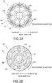
- FIG. 2A is a top view of the piston body 30 viewing from the second side and FIG. 2B is a bottom view thereof viewing from the first side.
- FIG. 3 is a sectional view of the piston body 30. In FIG. 3 , the piston rod 21, the compression-side damping valve 41, and the extension-side damping valve 51 are illustrated as well.
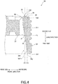
- FIG. 4 is a partial sectional view of the piston body 30.
- the piston body 30 includes a through-hole 30H formed at the radially inner side, compression-side oil paths 311 formed at the radially outer side of the through-hole 30H, and extension-side oil paths 312 formed at the radially outer side of the through-hole 30H.
- the piston body 30 includes, on the second side, a first inner round portion 32, a first outer round portion 33, a first tilt portion 34, and an outer end part 35.
- the piston body 30 includes, on the first side, a second inner round portion 36, a second outer round portion 37, and an annular protruded portion 38.
- the piston body 30 is formed, for example, by filling metal powder into a mold and sintering the filled metal powder.
- the through-how 30H is formed in the axial direction of the piston body 30.
- the piston rod 21 is inserted to the through-hole 30H.
- the compression-side oil paths 311 enable oil to flow between the first oil chamber Y1 and the second oil chamber Y2 in a compression stroke of the hydraulic buffer device 1.
- the compression-side oil paths 311 are arranged at a plurality of positions (eight positions in the present embodiment) at approximately even intervals in the circumferential direction.
- the extension-side oil paths 312 enable oil to flow between the second oil chamber Y2 and the first oil chamber Y1 in an extension stroke of the hydraulic buffer device 1.
- the extension-side oil paths 312 are arranged at a plurality of positions (eight positions in the present embodiment) at approximately even intervals in the circumferential direction.
- the first inner round portion 32 is formed approximately into an annular shape at the outer circumference of the through-hole 30H.
- the first inner round portion 32 is protruded toward the second side in the axial direction from a first end face 30A formed on the second side.
- the first inner round portion 32 is in contact with the compression-side damping valve 41 at the radially inner side.
- the first outer round portion 33 is formed approximately into an annular shape at the radially outer side of the compression-side oil paths 311.
- the first outer round portion 33 is protruded toward the second side in the axial direction from the first end face 30A.
- protrusion height of the first outer round portion 33 is slightly higher than that of the first inner round portion 32.
- the first outer round portion 33 is formed along a face that is approximately perpendicular to the axial direction.
- the first outer round portion 33 is most protruded on the second side of the piston body 30.
- the first outer round portion 33 is in contact with the compression-side damping valve 41 at the radially outer side.
- an end part of the first outer round portion 33 at the radially outer side is called a round end part 33E.
- the first tilt portion 34 is arranged as a face tilted to the axial direction as being connected to the first outer round portion 33 and the outer end part 35.
- the outer end part 35 is arranged as a face that is approximately perpendicular to the axial direction at the radially outer side of the first tilt portion 34.
- the second inner round portion 36 is formed approximately into an annular shape at the outer circumference of the through-hole 30H.
- the second inner round portion 36 is protruded toward the first side in the axial direction from a second end face 30B formed on the first side.
- the second inner round portion 36 is in contact with the extension-side damping valve 51 at the radially inner side.
- the second outer round portion 37 is formed approximately into an annular shape.
- the second outer round portion 37 is formed on the first side at the radially outer side of the extension-side oil paths 312 and at the radially inner side of the compression-side oil paths 311.
- the second outer round portion 37 is protruded toward the first side in the axial direction from the second end face 30B.
- protrusion height of the second outer round portion 37 is slightly higher than that of the second inner round portion 36.
- the second outer round portion 37 is protruded toward the extension-side damping valve 51 to form a part being in contact with the extension-side damping valve 51 at the radially outer side.
- a straight line passing through the second outer round portion 37 as being perpendicular to the axial direction is called a first imaginary line F1.
- a straight line passing through the round end part 33E of the first outer round portion33 as being parallel to the axial direction of the piston body 30 is called a second imaginary line F2.
- a point where the first imaginary line F1 and the second imaginary line F2 intersect is called an intersection point A.
- a line passing through a tilt end part 34E of the first tilt portion 34 as being parallel to the axial direction of the piston body 30 is called a third imaginary line F3.
- the annular protruded portion 38 is formed approximately into an annular shape as being arranged at the piston body 30 at the radially outer side.
- the annular protruded portion 38 is protruded largely more than the second outer round portion 37 in the axial direction. That is, the annular protruded portion 38 is protruded toward the first side from the first imaginary line F1.
- the annular protruded portion 38 includes an inner circumferential portion 381 arranged at the radially inner side and an end part 382 arranged on the first side.
- the inner circumferential portion 381 includes the first inner tilt portion 38T1 that is formed as a face tilted to the axial direction.
- An angle ⁇ 1 between the first inner tilt portion 38T1 and the axial direction is smaller than an angle ⁇ 0 between the first tilt portion 34 and the axial direction.
- the inner diameter of the first inner tilt portion 38T1 is increased from the second side toward the first side.
- the first inner tilt portion 38T1 is formed from the intersection point A to the end part 382. That is, at the radially inner side, the annular protruded portion 38 is formed only by the first inner tilt portion 38T1.
- the first inner tile portion 38T1 is arranged at the radially outer side of the first outer round portion 33.
- the end part 382 is formed as a face that is perpendicular to the axial direction as being connected to the inner circumferential portion 381 at the radially inner side.
- a connection portion between the inner circumferential portion 381 and the end part 382 i.e., a connection position between the first inner tilt portion 38T1 and the end part 382 is called a connection portion 38J.
- connection portion 38J is located at the radially outer side of the second imaginary line F2. That is, the end part 382 is arranged at the radially outer side of the first round portion 33. Further, the connection portion 38J is located at the radially outer side of the third imaginary line F3. That is, the end part 382 is arranged at the radially outer side of the first tilt portion 34.
- the compression-side damping valve 41 is, for example, a metal-made disc-shaped plate.
- the compression-side damping valve 41 has an opening 41H, at the radially inner side, through which the piston rod 21 passes.
- the compression-side damping valve 41 is formed to have a larger diameter than the first outer round portion 33.
- the compression-side damping valve 41 covers the second side of the compression-side oil path 311 and continuously opens the second side of the extension-side oil path 312.
- the extension-side damping valve 51 is, for example, a metal-made disc-shaped plate.
- the extension-side damping valve 51 has an opening 51H, at the radially inner side, through which the piston rod 21 passes.
- the extension-side damping valve 51 is formed to have a larger diameter than the second outer round portion 37.
- the extension-side damping valve 51 closes the first side of the extension-side oil path 312 and continuously opens the first side of the compression-side oil path 311.
- the hydraulic buffer device 1 of the present embodiment structured as described above operates as follows.
- the hydraulic buffer device 1 generates damping force in accordance with movement of the piston portion 100.
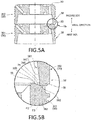
- FIGs. 5A and 5B are views illustrating a state that the piston bodies 30 are stacked.
- FIG. 5A is a sectional view of the stacked piston bodies 30 and
- FIG. 5B is an enlarged view of a region Vb illustrated in FIG. 5A .
- piston body 30 placed on the first side is called a first-side piston body 301 and the piston body 30 placed on the second side is called a second-side piston body 302.
- the end part 382 of the annular protruded portion 38 of the second-side piston body 302 faces to the outer end part 35 of the first-side piston body 301.
- connection portion 38J of the second-side piston body 302 is arranged at the radially inner side of the second imaginary line F2. Accordingly, the annular protruded portion 38 of the second-side piston body 302 is not contacted to the first outer round portion 33 of the first-side piston body 301.
- the first outer round portion 33 to which the compression-side damping valve 41 is contacted exerts a potent influence on damper force characteristics. In the present embodiment, contact of the annular protruded portion 38 with the first outer round portion 33 is suppressed.
- connection portion 38J of the second-side piston body 302 is arranged at the radially outer side of the third imaginary line F3. Accordingly, the annular protruded portion 38 of the second-side piston body 302 is not contacted as well to the first tilt portion 34 of the first-side piston body 301.
- the first inner tilt portion 38T1 is arranged, for example, at the annular protruded portion 38. Accordingly, when the piston body 30 is formed by molding for example, a mold body as the piston body 30 is easily ejected from the mold. Thus, the piston body 30 of the present embodiment is formed into a shape to be easily manufactured.
- the inner circumferential portion 381 of the annular protruded portion 38 is formed into a tilt shape, stress can be relieved to provide advantage in strength, for example, compared to a stepped shape.
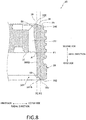
- FIG. 6 is a partial sectional view of the piston body 30 of a first modified example.
- the inner circumferential portion 381 has a different shape from that in the abovementioned embodiment. In the following, detailed description will be provided on the shape of the inner circumferential portion 381 of the first modified example.
- the inner circumferential portion 381 includes a first linear portion 38S1 and a second inner tilt portion 38T2.
- the first linear portion 38S1 is formed approximately in a straight line shape along the axial direction.
- a second side end of the first linear portion 38S1 is located at the intersection point A and a first side end thereof is located at a position being closer to the intersection point A than the center of the annular protruded portion 38 in the axial direction.
- the first linear portion 38S1 is shorter than the second inner tilt portion 38T2.
- the second inner tilt portion 38T2 is formed as a face tilted to the axial direction.
- An angle ⁇ 2 between the second inner tilt portion 38T2 and the axial direction is smaller than the angle ⁇ 0 between the first tilt portion 34 and the axial direction.
- the inner diameter of the second inner tilt portion 38T2 is increased from the second side toward the first side.
- the second inner tilt portion 38T2 (an example of the tilt portion) is arranged at the radially outer side of the first outer round portion 33 (an example of the first protruded portion).
- the first linear portion 38S1 is formed along the second imaginary line F2. Accordingly, the first linear portion 38S1 is arranged at the radially outer side of the first outer round portion 33.
- the connection portion 38J (a connection position between the second inner tilt portion 38T2 and the end part 382 in the first modified example) is formed at the radially outer side of the second imaginary line F2. That is, the end part 382 is arranged at the radially outer side of the first outer round portion 33. Further, the connection portion 38J is formed at the radially outer side of the third imaginary line F3. That is, the end part 382 is arranged at the radially outer side of the first tilt portion 34.
- the piston body 30 of the first modified example is formed into a shape to be easily manufactured.
- FIG. 7 is a partial sectional view of the piston body 30 of a second modified example.
- the inner circumferential portion 381 has a different shape from that in the abovementioned embodiment. In the following, detailed description will be provided on the shape of the inner circumferential portion 381 of the second modified example.
- the inner circumferential portion 381 includes a second linear portion 38S2, a third inner tilt portion 38T3 (an example of the first tilt portion), and a fourth inner tilt portion 38T4 (an example of the second tilt portion).
- the second linear portion 38S2 is formed approximately in a straight line shape along the axial direction. A second side end of the second linear portion 3852 is located at the intersection point A and a first side end thereof is located at a position being closer to the intersection point A than the center of the annular protruded portion 38 in the axial direction. Further, the second linear portion 38S2 is shorter than the third inner tilt portion 38T3.
- the third inner tilt portion 38T3 is formed as a face tilted to the axial direction.
- An angle ⁇ 3 between the third inner tilt portion 38T3 and the axial direction is smaller than the angle ⁇ 0 between the first tilt portion 34 and the axial direction.
- the inner diameter of the third inner tilt portion 38T3 is increased from the second side toward the first side.
- the fourth inner tilt portion 38T4 is formed as a face tilted to the axial direction as being continued from the third inner tilt portion 38T3.
- An angle ⁇ 4 between the fourth inner tilt portion 38T4 and the axial direction is smaller than the angle ⁇ 0 between the first tilt portion 34 and the axial direction.
- the angle ⁇ 4 between the fourth inner tilt portion 38T4 and the axial direction is larger than the angle ⁇ 3 between the third inner tilt portion 38T3 and the axial direction.
- the inner diameter of the fourth inner tilt portion 38T4 is increased from the second side toward the first side.
- the fourth inner tilt portion 38T4 is shorter than the third inner tilt portion 38T3.
- the third inner tilt portion 38T3 and the fourth inner tilt portion 38T4 (examples of the tilt portion) are arranged at the radially outer side of the first outer round portion 33 (an example of the first protruded portion).
- the inner circumferential portion 381 of the annular protruded portion 38 is simply required to have an inner diameter at the first side being larger than that at the second side.
- magnitude relation between the angles of the third inner tilt portion 38T3 and the fourth inner tilt portion 38T4 with respect to the axial direction may be reversed with respect to the abovementioned relation. That is, it is simply required that the angle ⁇ 3 between the third inner tilt portion 38T3 and the axial direction is different from the angle ⁇ 4 between the fourth inner tilt portion 38T4 and the axial direction.
- connection portion 38J (a connection position between the fourth inner tilt portion 38T4 and the end part 382 in the second modified example) is formed at the radially outer side of the second imaginary line F2. That is, the end part 382 is arranged at the radially outer side of the first outer round portion 33. Further, the connection portion 38J is formed at the radially outer side of the third imaginary line F3. That is, the end part 382 is arranged at the radially outer side of the first tilt portion 34.
- the piston body 30 of the second modified example is formed into a shape to be easily manufactured.
- FIG. 8 is a partial sectional view of the piston body 30 of a third modified example.
- the inner circumferential portion 381 has a different shape from that in the abovementioned embodiment. In the following, detailed description will be provided on the shape of the inner circumferential portion 381 of the third modified example.
- the inner circumferential portion 381 includes a third linear portion 38S3 and a fifth inner tilt portion 38T5.
- the third linear portion 38S3 is formed approximately in a straight line shape along the axial direction.
- a second side end of the third linear portion 38S2 is located at the intersection point A and a first side end thereof is located at a position being closer to the first side than the center of the annular protruded portion 38 in the axial direction.
- the fifth inner tilt portion 38T5 is formed as a face tilted to the axial direction. An angle ⁇ 5 between the fifth inner tilt portion 38T5 and the axial direction is smaller than the angle ⁇ 0 between the first tilt portion 34 and the axial direction. The inner diameter of the fifth inner tilt portion 38T5 is increased from the second side toward the first side. The fifth inner tilt portion 38T5 is shorter than the third linear portion 38S3. The fifth inner tilt portion 38T5 (an example of the tilt portion) is arranged at the radially outer side of the first outer round portion 33 (an example of the first protruded portion).
- connection portion 38J (a connection position between the fifth inner tilt portion 38T5 and the end part 382 in the third modified example) is formed at the radially outer side of the second imaginary line F2. That is, the end part 382 is arranged at the radially outer side of the first outer round portion 33. Further, the connection portion 38J is formed at the radially outer side of the third imaginary line F3. That is, the end part 382 is arranged at the radially outer side of the first tilt portion 34.
- the piston body 30 of the third modified example is formed into a shape to be easily manufactured.
- FIG. 9 is a partial sectional view of the piston body 30 of a fourth modified example.
- the inner circumferential portion 381 has a different shape from that in the abovementioned embodiment. In the following, detailed description will be provided on the shape of the inner circumferential portion 381 of the fourth modified example.
- the inner circumferential portion 381 includes a sixth inner tilt portion 38T6.
- the sixth inner tilt portion 38T6 is formed as a face tilted to the axial direction.
- An angle ⁇ 6 between the sixth inner tilt portion 38T6 and the axial direction is smaller than the angle ⁇ 0 between the first tilt portion 34 and the axial direction.
- the inner diameter of the sixth inner tilt portion 38T6 is increased from the second side toward the first side.
- the sixth inner tilt portion 38T6 is formed from a position at the radially inner side of the intersection point A to the end part 382. That is, in the piston body 30, the sixth inner tilt portion 38T6 (an example of the tilt portion) is arranged at a position being aligned with the first outer round portion 33 (an example of the first protruded portion) in the axial direction.
- the inner circumferential portion 381 of the fourth modified example is formed only of the sixth inner tilt portion 38T6.
- connection portion 38J (a connection position between the sixth inner tilt portion 38T6 and the end part 382 in the fourth modified example) is formed at the radially outer side of the second imaginary line F2. That is, the end part 382 is arranged at the radially outer side of the first outer round portion 33. Further, the connection portion 38J is formed at the radially outer side of the third imaginary line F3. That is, the end part 382 is arranged at the radially outer side of the first tilt portion 34.
- the piston body 30 of the fourth modified example is formed into a shape to be easily manufactured.
- a part of the inner tilt portion (each of the second to fifth inner tilt portions 38T2, 38T3, 38T4, 38T5) may be located at the radially inner side of the second imaginary line F2. That is, the inner tilt portion (each of the second to fifth inner tilt portions 38T2, 38T3, 38T4, 38T5) may be arranged at a position being aligned with the first outer round portion 33 in the axial direction.
- the inner tilt portion is simply required to be arranged not to be contacted to the first outer round portion 33.
- the annular protruded portion 38 is formed into an annular shape.
- the annular protruded portion 38 may have, for example, a cutout at a part thereof in the circumferential direction.
- the annular protruded portion 38 may be formed of a plurality of protruded portions discontinuously formed in the circumferential direction.
- the hydraulic buffer device 1 has a so-called double-cylinder structure.
- a triple-cylinder structure may be adopted.
- the structure of the piston portion 100 of the abovementioned embodiment may be adopted instead of the bottom valve portion 60.
- the structure of the piston portion 100 may be arranged in an accommodation portion, being separated from the first cylinder 11, through which oil flows in accordance with movement of the piston rod 21.
Landscapes
- Engineering & Computer Science (AREA)
- General Engineering & Computer Science (AREA)
- Mechanical Engineering (AREA)
- Fluid-Damping Devices (AREA)
Applications Claiming Priority (1)
| Application Number | Priority Date | Filing Date | Title |
|---|---|---|---|
| JP2016034350A JP6594226B2 (ja) | 2016-02-25 | 2016-02-25 | 圧力緩衝装置および流路形成部材 |
Publications (2)
| Publication Number | Publication Date |
|---|---|
| EP3211264A1 true EP3211264A1 (de) | 2017-08-30 |
| EP3211264B1 EP3211264B1 (de) | 2019-12-25 |
Family
ID=57906451
Family Applications (1)
| Application Number | Title | Priority Date | Filing Date |
|---|---|---|---|
| EP17152557.9A Active EP3211264B1 (de) | 2016-02-25 | 2017-01-23 | Druckpuffervorrichtung und strömungswegformelement |
Country Status (4)
| Country | Link |
|---|---|
| US (1) | US10138975B2 (de) |
| EP (1) | EP3211264B1 (de) |
| JP (1) | JP6594226B2 (de) |
| CN (1) | CN107120379B (de) |
Families Citing this family (2)
| Publication number | Priority date | Publication date | Assignee | Title |
|---|---|---|---|---|
| JP6291633B1 (ja) | 2017-10-04 | 2018-03-14 | 株式会社ショーワ | 圧力緩衝装置および減衰力発生機構 |
| DE112020004785T5 (de) * | 2019-10-02 | 2022-06-15 | Hitachi Astemo, Ltd. | Stossdämpfer |
Citations (4)
| Publication number | Priority date | Publication date | Assignee | Title |
|---|---|---|---|---|
| DE102010040458A1 (de) * | 2010-09-09 | 2012-03-15 | Zf Friedrichshafen Ag | Dämpfventil für einen Schwingungsdämpfer |
| WO2014077265A1 (ja) * | 2012-11-16 | 2014-05-22 | カヤバ工業株式会社 | ピストン |
| JP2014152812A (ja) | 2013-02-06 | 2014-08-25 | Kayaba Ind Co Ltd | ピストン及びピストンを備える緩衝器 |
| WO2015177880A1 (ja) * | 2014-05-20 | 2015-11-26 | 株式会社ショーワ | 圧力緩衝装置および減衰力発生部材 |
Family Cites Families (9)
| Publication number | Priority date | Publication date | Assignee | Title |
|---|---|---|---|---|
| US3730305A (en) * | 1971-04-16 | 1973-05-01 | Ford Motor Co | Shock absorber piston |
| JP3383863B2 (ja) * | 1993-03-08 | 2003-03-10 | トキコ株式会社 | 減衰力調整式油圧緩衝器 |
| FR2738889B1 (fr) * | 1995-09-20 | 1997-10-31 | Soframca | Piston a clapet pour tube d'amortisseur hydraulique |
| US6371264B1 (en) * | 1999-06-09 | 2002-04-16 | Denso Corporation | Fulcrum blow off valve for use in a shock absorber |
| US6886670B2 (en) | 2003-09-29 | 2005-05-03 | Tenneco Automotive Operating Company Inc. | Extra support land for valve disc |
| DE102004050732A1 (de) * | 2003-12-01 | 2005-06-23 | Zf Friedrichshafen Ag | Dämpfventileinrichtung mit progressiver Dämpfkraftkennlinie |
| DE102004058965B4 (de) * | 2004-12-08 | 2010-07-08 | Zf Friedrichshafen Ag | Schwingungsdämpfer mit amplitudenselektiver Dämpfkraft |
| JP2009209960A (ja) * | 2008-02-29 | 2009-09-17 | Hitachi Ltd | 緩衝器 |
| DE112013006893B4 (de) | 2013-03-29 | 2023-07-27 | Hitachi Astemo, Ltd. | Druckdämpfungsvorrichtung |
-
2016
- 2016-02-25 JP JP2016034350A patent/JP6594226B2/ja active Active
-
2017
- 2017-01-13 US US15/405,445 patent/US10138975B2/en active Active
- 2017-01-23 CN CN201710058372.3A patent/CN107120379B/zh active Active
- 2017-01-23 EP EP17152557.9A patent/EP3211264B1/de active Active
Patent Citations (4)
| Publication number | Priority date | Publication date | Assignee | Title |
|---|---|---|---|---|
| DE102010040458A1 (de) * | 2010-09-09 | 2012-03-15 | Zf Friedrichshafen Ag | Dämpfventil für einen Schwingungsdämpfer |
| WO2014077265A1 (ja) * | 2012-11-16 | 2014-05-22 | カヤバ工業株式会社 | ピストン |
| JP2014152812A (ja) | 2013-02-06 | 2014-08-25 | Kayaba Ind Co Ltd | ピストン及びピストンを備える緩衝器 |
| WO2015177880A1 (ja) * | 2014-05-20 | 2015-11-26 | 株式会社ショーワ | 圧力緩衝装置および減衰力発生部材 |
Also Published As
| Publication number | Publication date |
|---|---|
| JP6594226B2 (ja) | 2019-10-23 |
| US10138975B2 (en) | 2018-11-27 |
| CN107120379B (zh) | 2019-05-03 |
| CN107120379A (zh) | 2017-09-01 |
| JP2017150591A (ja) | 2017-08-31 |
| US20170248188A1 (en) | 2017-08-31 |
| EP3211264B1 (de) | 2019-12-25 |
Similar Documents
| Publication | Publication Date | Title |
|---|---|---|
| US9410595B2 (en) | Damping valve for shock absorber | |
| US10655701B2 (en) | Adjustable oscillation damper | |
| CN107636344B (zh) | 用于车辆悬架的液压减震器 | |
| US8887882B2 (en) | Vibration damper with integrated level control | |
| US10030786B2 (en) | Adjustable damping valve arrangement | |
| US20180119770A1 (en) | Hydraulic compression stop member for a hydraulic shock-absorber for a vehicle suspension with pressure relief device | |
| US8113324B2 (en) | Damping valve for a vibration damper | |
| JP6872539B2 (ja) | ポペットバルブ及びポペットバルブを含むピストンコンプレッサ | |
| JP6942185B2 (ja) | 緩衝器およびその製造方法 | |
| US9915315B2 (en) | Production of multi-part, joined valve components in hydraulic applications with joint sealing profiles | |
| US20190226547A1 (en) | Damping Valve For A Vibration Damper | |
| US20160169316A1 (en) | Mono-tube type hydraulic shock absorber | |
| TR201806759T4 (tr) | Bir hidrolik cihazda değişken yükü kontrol etmek için sistem. | |
| EP3211264B1 (de) | Druckpuffervorrichtung und strömungswegformelement | |
| US20150211634A1 (en) | Shock absorber and piston | |
| CN115217884A (zh) | 具有液压压力止挡的减振器 | |
| WO2017047526A1 (ja) | 緩衝器 | |
| KR102740094B1 (ko) | 조립체, 완충기 및 조립체의 제조 방법 | |
| US10145440B2 (en) | Pressure buffer device and damping force generating member | |
| US11231082B2 (en) | Hydraulic damping device | |
| US6644446B2 (en) | Hydraulic shock-absorber | |
| US20190390731A1 (en) | Hydraulic damping device | |
| US20180245656A1 (en) | Bellows accumulator, in particular pulsation damper | |
| JP2005172128A (ja) | 油入緩衝器 | |
| EP3039313A1 (de) | Einzelrohrdämpferanordnung |
Legal Events
| Date | Code | Title | Description |
|---|---|---|---|
| PUAI | Public reference made under article 153(3) epc to a published international application that has entered the european phase |
Free format text: ORIGINAL CODE: 0009012 |
|
| STAA | Information on the status of an ep patent application or granted ep patent |
Free format text: STATUS: THE APPLICATION HAS BEEN PUBLISHED |
|
| AK | Designated contracting states |
Kind code of ref document: A1 Designated state(s): AL AT BE BG CH CY CZ DE DK EE ES FI FR GB GR HR HU IE IS IT LI LT LU LV MC MK MT NL NO PL PT RO RS SE SI SK SM TR |
|
| AX | Request for extension of the european patent |
Extension state: BA ME |
|
| STAA | Information on the status of an ep patent application or granted ep patent |
Free format text: STATUS: REQUEST FOR EXAMINATION WAS MADE |
|
| 17P | Request for examination filed |
Effective date: 20180216 |
|
| RBV | Designated contracting states (corrected) |
Designated state(s): AL AT BE BG CH CY CZ DE DK EE ES FI FR GB GR HR HU IE IS IT LI LT LU LV MC MK MT NL NO PL PT RO RS SE SI SK SM TR |
|
| STAA | Information on the status of an ep patent application or granted ep patent |
Free format text: STATUS: EXAMINATION IS IN PROGRESS |
|
| 17Q | First examination report despatched |
Effective date: 20180627 |
|
| REG | Reference to a national code |
Ref country code: DE Ref legal event code: R079 Ref document number: 602017009969 Country of ref document: DE Free format text: PREVIOUS MAIN CLASS: F16F0009320000 Ipc: F16F0009348000 |
|
| RIC1 | Information provided on ipc code assigned before grant |
Ipc: F16F 9/32 20060101ALI20190228BHEP Ipc: F16F 9/348 20060101AFI20190228BHEP |
|
| GRAP | Despatch of communication of intention to grant a patent |
Free format text: ORIGINAL CODE: EPIDOSNIGR1 |
|
| STAA | Information on the status of an ep patent application or granted ep patent |
Free format text: STATUS: GRANT OF PATENT IS INTENDED |
|
| INTG | Intention to grant announced |
Effective date: 20190715 |
|
| GRAS | Grant fee paid |
Free format text: ORIGINAL CODE: EPIDOSNIGR3 |
|
| GRAA | (expected) grant |
Free format text: ORIGINAL CODE: 0009210 |
|
| STAA | Information on the status of an ep patent application or granted ep patent |
Free format text: STATUS: THE PATENT HAS BEEN GRANTED |
|
| AK | Designated contracting states |
Kind code of ref document: B1 Designated state(s): AL AT BE BG CH CY CZ DE DK EE ES FI FR GB GR HR HU IE IS IT LI LT LU LV MC MK MT NL NO PL PT RO RS SE SI SK SM TR |
|
| REG | Reference to a national code |
Ref country code: GB Ref legal event code: FG4D |
|
| REG | Reference to a national code |
Ref country code: CH Ref legal event code: EP |
|
| REG | Reference to a national code |
Ref country code: AT Ref legal event code: REF Ref document number: 1217463 Country of ref document: AT Kind code of ref document: T Effective date: 20200115 |
|
| REG | Reference to a national code |
Ref country code: DE Ref legal event code: R096 Ref document number: 602017009969 Country of ref document: DE |
|
| REG | Reference to a national code |
Ref country code: IE Ref legal event code: FG4D |
|
| REG | Reference to a national code |
Ref country code: NL Ref legal event code: MP Effective date: 20191225 |
|
| PG25 | Lapsed in a contracting state [announced via postgrant information from national office to epo] |
Ref country code: LT Free format text: LAPSE BECAUSE OF FAILURE TO SUBMIT A TRANSLATION OF THE DESCRIPTION OR TO PAY THE FEE WITHIN THE PRESCRIBED TIME-LIMIT Effective date: 20191225 Ref country code: SE Free format text: LAPSE BECAUSE OF FAILURE TO SUBMIT A TRANSLATION OF THE DESCRIPTION OR TO PAY THE FEE WITHIN THE PRESCRIBED TIME-LIMIT Effective date: 20191225 Ref country code: LV Free format text: LAPSE BECAUSE OF FAILURE TO SUBMIT A TRANSLATION OF THE DESCRIPTION OR TO PAY THE FEE WITHIN THE PRESCRIBED TIME-LIMIT Effective date: 20191225 Ref country code: GR Free format text: LAPSE BECAUSE OF FAILURE TO SUBMIT A TRANSLATION OF THE DESCRIPTION OR TO PAY THE FEE WITHIN THE PRESCRIBED TIME-LIMIT Effective date: 20200326 Ref country code: NO Free format text: LAPSE BECAUSE OF FAILURE TO SUBMIT A TRANSLATION OF THE DESCRIPTION OR TO PAY THE FEE WITHIN THE PRESCRIBED TIME-LIMIT Effective date: 20200325 Ref country code: BG Free format text: LAPSE BECAUSE OF FAILURE TO SUBMIT A TRANSLATION OF THE DESCRIPTION OR TO PAY THE FEE WITHIN THE PRESCRIBED TIME-LIMIT Effective date: 20200325 Ref country code: FI Free format text: LAPSE BECAUSE OF FAILURE TO SUBMIT A TRANSLATION OF THE DESCRIPTION OR TO PAY THE FEE WITHIN THE PRESCRIBED TIME-LIMIT Effective date: 20191225 |
|
| REG | Reference to a national code |
Ref country code: LT Ref legal event code: MG4D |
|
| PG25 | Lapsed in a contracting state [announced via postgrant information from national office to epo] |
Ref country code: RS Free format text: LAPSE BECAUSE OF FAILURE TO SUBMIT A TRANSLATION OF THE DESCRIPTION OR TO PAY THE FEE WITHIN THE PRESCRIBED TIME-LIMIT Effective date: 20191225 Ref country code: HR Free format text: LAPSE BECAUSE OF FAILURE TO SUBMIT A TRANSLATION OF THE DESCRIPTION OR TO PAY THE FEE WITHIN THE PRESCRIBED TIME-LIMIT Effective date: 20191225 |
|
| PG25 | Lapsed in a contracting state [announced via postgrant information from national office to epo] |
Ref country code: AL Free format text: LAPSE BECAUSE OF FAILURE TO SUBMIT A TRANSLATION OF THE DESCRIPTION OR TO PAY THE FEE WITHIN THE PRESCRIBED TIME-LIMIT Effective date: 20191225 |
|
| PG25 | Lapsed in a contracting state [announced via postgrant information from national office to epo] |
Ref country code: NL Free format text: LAPSE BECAUSE OF FAILURE TO SUBMIT A TRANSLATION OF THE DESCRIPTION OR TO PAY THE FEE WITHIN THE PRESCRIBED TIME-LIMIT Effective date: 20191225 Ref country code: CZ Free format text: LAPSE BECAUSE OF FAILURE TO SUBMIT A TRANSLATION OF THE DESCRIPTION OR TO PAY THE FEE WITHIN THE PRESCRIBED TIME-LIMIT Effective date: 20191225 Ref country code: RO Free format text: LAPSE BECAUSE OF FAILURE TO SUBMIT A TRANSLATION OF THE DESCRIPTION OR TO PAY THE FEE WITHIN THE PRESCRIBED TIME-LIMIT Effective date: 20191225 Ref country code: PT Free format text: LAPSE BECAUSE OF FAILURE TO SUBMIT A TRANSLATION OF THE DESCRIPTION OR TO PAY THE FEE WITHIN THE PRESCRIBED TIME-LIMIT Effective date: 20200520 Ref country code: EE Free format text: LAPSE BECAUSE OF FAILURE TO SUBMIT A TRANSLATION OF THE DESCRIPTION OR TO PAY THE FEE WITHIN THE PRESCRIBED TIME-LIMIT Effective date: 20191225 |
|
| PG25 | Lapsed in a contracting state [announced via postgrant information from national office to epo] |
Ref country code: IS Free format text: LAPSE BECAUSE OF FAILURE TO SUBMIT A TRANSLATION OF THE DESCRIPTION OR TO PAY THE FEE WITHIN THE PRESCRIBED TIME-LIMIT Effective date: 20200425 Ref country code: SK Free format text: LAPSE BECAUSE OF FAILURE TO SUBMIT A TRANSLATION OF THE DESCRIPTION OR TO PAY THE FEE WITHIN THE PRESCRIBED TIME-LIMIT Effective date: 20191225 Ref country code: SM Free format text: LAPSE BECAUSE OF FAILURE TO SUBMIT A TRANSLATION OF THE DESCRIPTION OR TO PAY THE FEE WITHIN THE PRESCRIBED TIME-LIMIT Effective date: 20191225 |
|
| REG | Reference to a national code |
Ref country code: CH Ref legal event code: PL |
|
| REG | Reference to a national code |
Ref country code: DE Ref legal event code: R097 Ref document number: 602017009969 Country of ref document: DE |
|
| PG25 | Lapsed in a contracting state [announced via postgrant information from national office to epo] |
Ref country code: MC Free format text: LAPSE BECAUSE OF FAILURE TO SUBMIT A TRANSLATION OF THE DESCRIPTION OR TO PAY THE FEE WITHIN THE PRESCRIBED TIME-LIMIT Effective date: 20191225 |
|
| REG | Reference to a national code |
Ref country code: BE Ref legal event code: MM Effective date: 20200131 |
|
| PG25 | Lapsed in a contracting state [announced via postgrant information from national office to epo] |
Ref country code: ES Free format text: LAPSE BECAUSE OF FAILURE TO SUBMIT A TRANSLATION OF THE DESCRIPTION OR TO PAY THE FEE WITHIN THE PRESCRIBED TIME-LIMIT Effective date: 20191225 Ref country code: LU Free format text: LAPSE BECAUSE OF NON-PAYMENT OF DUE FEES Effective date: 20200123 Ref country code: DK Free format text: LAPSE BECAUSE OF FAILURE TO SUBMIT A TRANSLATION OF THE DESCRIPTION OR TO PAY THE FEE WITHIN THE PRESCRIBED TIME-LIMIT Effective date: 20191225 |
|
| PLBE | No opposition filed within time limit |
Free format text: ORIGINAL CODE: 0009261 |
|
| STAA | Information on the status of an ep patent application or granted ep patent |
Free format text: STATUS: NO OPPOSITION FILED WITHIN TIME LIMIT |
|
| REG | Reference to a national code |
Ref country code: AT Ref legal event code: MK05 Ref document number: 1217463 Country of ref document: AT Kind code of ref document: T Effective date: 20191225 |
|
| PG25 | Lapsed in a contracting state [announced via postgrant information from national office to epo] |
Ref country code: BE Free format text: LAPSE BECAUSE OF NON-PAYMENT OF DUE FEES Effective date: 20200131 Ref country code: SI Free format text: LAPSE BECAUSE OF FAILURE TO SUBMIT A TRANSLATION OF THE DESCRIPTION OR TO PAY THE FEE WITHIN THE PRESCRIBED TIME-LIMIT Effective date: 20191225 Ref country code: LI Free format text: LAPSE BECAUSE OF NON-PAYMENT OF DUE FEES Effective date: 20200131 Ref country code: CH Free format text: LAPSE BECAUSE OF NON-PAYMENT OF DUE FEES Effective date: 20200131 |
|
| 26N | No opposition filed |
Effective date: 20200928 |
|
| PG25 | Lapsed in a contracting state [announced via postgrant information from national office to epo] |
Ref country code: IE Free format text: LAPSE BECAUSE OF NON-PAYMENT OF DUE FEES Effective date: 20200123 Ref country code: AT Free format text: LAPSE BECAUSE OF FAILURE TO SUBMIT A TRANSLATION OF THE DESCRIPTION OR TO PAY THE FEE WITHIN THE PRESCRIBED TIME-LIMIT Effective date: 20191225 Ref country code: FR Free format text: LAPSE BECAUSE OF NON-PAYMENT OF DUE FEES Effective date: 20200225 Ref country code: IT Free format text: LAPSE BECAUSE OF FAILURE TO SUBMIT A TRANSLATION OF THE DESCRIPTION OR TO PAY THE FEE WITHIN THE PRESCRIBED TIME-LIMIT Effective date: 20191225 |
|
| PG25 | Lapsed in a contracting state [announced via postgrant information from national office to epo] |
Ref country code: PL Free format text: LAPSE BECAUSE OF FAILURE TO SUBMIT A TRANSLATION OF THE DESCRIPTION OR TO PAY THE FEE WITHIN THE PRESCRIBED TIME-LIMIT Effective date: 20191225 |
|
| REG | Reference to a national code |
Ref country code: DE Ref legal event code: R081 Ref document number: 602017009969 Country of ref document: DE Owner name: HITACHI ASTEMO, LTD., HITACHINAKA-SHI, JP Free format text: FORMER OWNER: SHOWA CORPORATION, GYODA CITY, SAITAMA, JP Ref country code: GB Ref legal event code: 732E Free format text: REGISTERED BETWEEN 20211216 AND 20211222 |
|
| PG25 | Lapsed in a contracting state [announced via postgrant information from national office to epo] |
Ref country code: TR Free format text: LAPSE BECAUSE OF FAILURE TO SUBMIT A TRANSLATION OF THE DESCRIPTION OR TO PAY THE FEE WITHIN THE PRESCRIBED TIME-LIMIT Effective date: 20191225 Ref country code: MT Free format text: LAPSE BECAUSE OF FAILURE TO SUBMIT A TRANSLATION OF THE DESCRIPTION OR TO PAY THE FEE WITHIN THE PRESCRIBED TIME-LIMIT Effective date: 20191225 Ref country code: CY Free format text: LAPSE BECAUSE OF FAILURE TO SUBMIT A TRANSLATION OF THE DESCRIPTION OR TO PAY THE FEE WITHIN THE PRESCRIBED TIME-LIMIT Effective date: 20191225 |
|
| PG25 | Lapsed in a contracting state [announced via postgrant information from national office to epo] |
Ref country code: MK Free format text: LAPSE BECAUSE OF FAILURE TO SUBMIT A TRANSLATION OF THE DESCRIPTION OR TO PAY THE FEE WITHIN THE PRESCRIBED TIME-LIMIT Effective date: 20191225 |
|
| REG | Reference to a national code |
Ref country code: DE Ref legal event code: R082 Ref document number: 602017009969 Country of ref document: DE Representative=s name: MAUCHER JENKINS PATENTANWAELTE & RECHTSANWAELT, DE |
|
| PGFP | Annual fee paid to national office [announced via postgrant information from national office to epo] |
Ref country code: GB Payment date: 20251204 Year of fee payment: 10 |
|
| PGFP | Annual fee paid to national office [announced via postgrant information from national office to epo] |
Ref country code: DE Payment date: 20251203 Year of fee payment: 10 |