EP3211246B1 - Luftausblasvorrichtung - Google Patents
Luftausblasvorrichtung Download PDFInfo
- Publication number
- EP3211246B1 EP3211246B1 EP14904425.7A EP14904425A EP3211246B1 EP 3211246 B1 EP3211246 B1 EP 3211246B1 EP 14904425 A EP14904425 A EP 14904425A EP 3211246 B1 EP3211246 B1 EP 3211246B1
- Authority
- EP
- European Patent Office
- Prior art keywords
- parts
- engaging
- ring member
- cylinder unit
- pair
- Prior art date
- Legal status (The legal status is an assumption and is not a legal conclusion. Google has not performed a legal analysis and makes no representation as to the accuracy of the status listed.)
- Active
Links
Images


Classifications
-
- A—HUMAN NECESSITIES
- A47—FURNITURE; DOMESTIC ARTICLES OR APPLIANCES; COFFEE MILLS; SPICE MILLS; SUCTION CLEANERS IN GENERAL
- A47C—CHAIRS; SOFAS; BEDS
- A47C7/00—Parts, details, or accessories of chairs or stools
- A47C7/02—Seat parts
- A47C7/021—Detachable or loose seat cushions
-
- F—MECHANICAL ENGINEERING; LIGHTING; HEATING; WEAPONS; BLASTING
- F04—POSITIVE - DISPLACEMENT MACHINES FOR LIQUIDS; PUMPS FOR LIQUIDS OR ELASTIC FLUIDS
- F04D—NON-POSITIVE-DISPLACEMENT PUMPS
- F04D29/00—Details, component parts, or accessories
- F04D29/60—Mounting; Assembling; Disassembling
- F04D29/64—Mounting; Assembling; Disassembling of axial pumps
- F04D29/644—Mounting; Assembling; Disassembling of axial pumps especially adapted for elastic fluid pumps
-
- A—HUMAN NECESSITIES
- A47—FURNITURE; DOMESTIC ARTICLES OR APPLIANCES; COFFEE MILLS; SPICE MILLS; SUCTION CLEANERS IN GENERAL
- A47C—CHAIRS; SOFAS; BEDS
- A47C7/00—Parts, details, or accessories of chairs or stools
- A47C7/62—Accessories for chairs
- A47C7/72—Adaptations for incorporating lamps, radio sets, bars, telephones, ventilation, heating or cooling arrangements or the like
- A47C7/74—Adaptations for incorporating lamps, radio sets, bars, telephones, ventilation, heating or cooling arrangements or the like for ventilation, heating or cooling
- A47C7/742—Adaptations for incorporating lamps, radio sets, bars, telephones, ventilation, heating or cooling arrangements or the like for ventilation, heating or cooling for ventilating or cooling
- A47C7/744—Adaptations for incorporating lamps, radio sets, bars, telephones, ventilation, heating or cooling arrangements or the like for ventilation, heating or cooling for ventilating or cooling with active means, e.g. by using air blowers or liquid pumps
-
- F—MECHANICAL ENGINEERING; LIGHTING; HEATING; WEAPONS; BLASTING
- F04—POSITIVE - DISPLACEMENT MACHINES FOR LIQUIDS; PUMPS FOR LIQUIDS OR ELASTIC FLUIDS
- F04D—NON-POSITIVE-DISPLACEMENT PUMPS
- F04D25/00—Pumping installations or systems
- F04D25/02—Units comprising pumps and their driving means
- F04D25/08—Units comprising pumps and their driving means the working fluid being air, e.g. for ventilation
- F04D25/12—Units comprising pumps and their driving means the working fluid being air, e.g. for ventilation the unit being adapted for mounting in apertures
-
- F—MECHANICAL ENGINEERING; LIGHTING; HEATING; WEAPONS; BLASTING
- F04—POSITIVE - DISPLACEMENT MACHINES FOR LIQUIDS; PUMPS FOR LIQUIDS OR ELASTIC FLUIDS
- F04D—NON-POSITIVE-DISPLACEMENT PUMPS
- F04D29/00—Details, component parts, or accessories
- F04D29/02—Selection of particular materials
- F04D29/023—Selection of particular materials especially adapted for elastic fluid pumps
-
- F—MECHANICAL ENGINEERING; LIGHTING; HEATING; WEAPONS; BLASTING
- F04—POSITIVE - DISPLACEMENT MACHINES FOR LIQUIDS; PUMPS FOR LIQUIDS OR ELASTIC FLUIDS
- F04D—NON-POSITIVE-DISPLACEMENT PUMPS
- F04D29/00—Details, component parts, or accessories
- F04D29/40—Casings; Connections of working fluid
- F04D29/42—Casings; Connections of working fluid for radial or helico-centrifugal pumps
- F04D29/4206—Casings; Connections of working fluid for radial or helico-centrifugal pumps especially adapted for elastic fluid pumps
-
- F—MECHANICAL ENGINEERING; LIGHTING; HEATING; WEAPONS; BLASTING
- F04—POSITIVE - DISPLACEMENT MACHINES FOR LIQUIDS; PUMPS FOR LIQUIDS OR ELASTIC FLUIDS
- F04D—NON-POSITIVE-DISPLACEMENT PUMPS
- F04D29/00—Details, component parts, or accessories
- F04D29/40—Casings; Connections of working fluid
- F04D29/52—Casings; Connections of working fluid for axial pumps
- F04D29/522—Casings; Connections of working fluid for axial pumps especially adapted for elastic fluid pumps
-
- F—MECHANICAL ENGINEERING; LIGHTING; HEATING; WEAPONS; BLASTING
- F04—POSITIVE - DISPLACEMENT MACHINES FOR LIQUIDS; PUMPS FOR LIQUIDS OR ELASTIC FLUIDS
- F04D—NON-POSITIVE-DISPLACEMENT PUMPS
- F04D29/00—Details, component parts, or accessories
- F04D29/60—Mounting; Assembling; Disassembling
- F04D29/601—Mounting; Assembling; Disassembling specially adapted for elastic fluid pumps
- F04D29/602—Mounting in cavities
-
- F—MECHANICAL ENGINEERING; LIGHTING; HEATING; WEAPONS; BLASTING
- F04—POSITIVE - DISPLACEMENT MACHINES FOR LIQUIDS; PUMPS FOR LIQUIDS OR ELASTIC FLUIDS
- F04D—NON-POSITIVE-DISPLACEMENT PUMPS
- F04D29/00—Details, component parts, or accessories
- F04D29/60—Mounting; Assembling; Disassembling
- F04D29/62—Mounting; Assembling; Disassembling of radial or helico-centrifugal pumps
- F04D29/624—Mounting; Assembling; Disassembling of radial or helico-centrifugal pumps especially adapted for elastic fluid pumps
- F04D29/626—Mounting or removal of fans
-
- F—MECHANICAL ENGINEERING; LIGHTING; HEATING; WEAPONS; BLASTING
- F04—POSITIVE - DISPLACEMENT MACHINES FOR LIQUIDS; PUMPS FOR LIQUIDS OR ELASTIC FLUIDS
- F04D—NON-POSITIVE-DISPLACEMENT PUMPS
- F04D29/00—Details, component parts, or accessories
- F04D29/60—Mounting; Assembling; Disassembling
- F04D29/64—Mounting; Assembling; Disassembling of axial pumps
- F04D29/644—Mounting; Assembling; Disassembling of axial pumps especially adapted for elastic fluid pumps
- F04D29/646—Mounting or removal of fans
-
- A—HUMAN NECESSITIES
- A41—WEARING APPAREL
- A41D—OUTERWEAR; PROTECTIVE GARMENTS; ACCESSORIES
- A41D13/00—Professional, industrial or sporting protective garments, e.g. surgeons' gowns or garments protecting against blows or punches
- A41D13/002—Professional, industrial or sporting protective garments, e.g. surgeons' gowns or garments protecting against blows or punches with controlled internal environment
- A41D13/0025—Professional, industrial or sporting protective garments, e.g. surgeons' gowns or garments protecting against blows or punches with controlled internal environment by means of forced air circulation
-
- F—MECHANICAL ENGINEERING; LIGHTING; HEATING; WEAPONS; BLASTING
- F04—POSITIVE - DISPLACEMENT MACHINES FOR LIQUIDS; PUMPS FOR LIQUIDS OR ELASTIC FLUIDS
- F04D—NON-POSITIVE-DISPLACEMENT PUMPS
- F04D25/00—Pumping installations or systems
- F04D25/02—Units comprising pumps and their driving means
- F04D25/08—Units comprising pumps and their driving means the working fluid being air, e.g. for ventilation
- F04D25/084—Units comprising pumps and their driving means the working fluid being air, e.g. for ventilation hand fans
-
- F—MECHANICAL ENGINEERING; LIGHTING; HEATING; WEAPONS; BLASTING
- F05—INDEXING SCHEMES RELATING TO ENGINES OR PUMPS IN VARIOUS SUBCLASSES OF CLASSES F01-F04
- F05D—INDEXING SCHEME FOR ASPECTS RELATING TO NON-POSITIVE-DISPLACEMENT MACHINES OR ENGINES, GAS-TURBINES OR JET-PROPULSION PLANTS
- F05D2250/00—Geometry
- F05D2250/10—Two-dimensional
- F05D2250/14—Two-dimensional elliptical
-
- F—MECHANICAL ENGINEERING; LIGHTING; HEATING; WEAPONS; BLASTING
- F05—INDEXING SCHEMES RELATING TO ENGINES OR PUMPS IN VARIOUS SUBCLASSES OF CLASSES F01-F04
- F05D—INDEXING SCHEME FOR ASPECTS RELATING TO NON-POSITIVE-DISPLACEMENT MACHINES OR ENGINES, GAS-TURBINES OR JET-PROPULSION PLANTS
- F05D2300/00—Materials; Properties thereof
- F05D2300/50—Intrinsic material properties or characteristics
- F05D2300/501—Elasticity
Definitions
- the present invention relates to an air circulator which is used in an air circulation-type mat, an air conditioned outer wear and the like which evaporate the sweat coming out from a human body by circulating the air and which is attached to a sheet member that is the material of the air circulation-type mat, air conditioned outer wear and the like.
- an air circulation-type mat such as an air conditioned sitting mat includes a spacer, a sheet member and an air circulator.
- the spacer is for securing a space inside the air circulation-type mat.
- the sheet member is for covering the spacer and for example, a piece of cloth or the like is used as the sheet member.
- the air circulator is for generating an air flow inside the space which is secured by the spacer. Such air circulator is attached to the sheet member.
- the air circulators With respect to the air circulators which are used in the air circulation-type mats, air conditioned outer wears and the like, in order to improve the air conditioning effect, the air circulators need to be firmly attached to the sheet members so that the air does not leak from the attaching parts of the air circulators when operating and so that the air circulators do not come off easily from the sheet members. On the other hand, in cases where the sheet members need to be washed and the like, users need to be able to easily take off the air circulators from the sheet members.
- the conventional air circulators are configured so as to be attachable and detachable to and from the sheet members to a certain extent. However, when actually using them, the users cannot easily attach the air circulators to the sheet members and cannot easily detach the air circulators from the sheet members. Therefore, the conventional air circulators have a problem that they cannot be easily attached and detached.
- the present invention was made in view of the above problem and an object is to provide an air circulator having a simple configuration which allows a user to easily attach and detach the air circulator to and from a sheet member.
- the present invention is an air circulator according to independent claim 1. Preferred embodiments are set out in the dependent claims.
- the air circulator of the present invention has a simple configuration and a user can easily attach and detach the air circulator to and from a sheet member.
- FIG. 1(a) is a schematic perspective view where an air circulation-type mat for chair using an air circulator which is the first embodiment of the present invention is in use
- FIG. 1(b) is a schematic cross-sectional view where the air circulation-type mat is in use.
- the air circulation-type mat 100 for chair is used by laying it on the sitting surface of a chair.
- the air circulation-type mat 100 includes a bag-like sheet member 200, a spacer 102, an air outlet 103, an air circulator 1 of the present invention and a power supplying unit (not shown) such as a battery which supplies electricity to the air circulator 1.
- the bag-like sheet member 200 is for covering the spacer 102.
- the spacer 102 is for securing a space inside the sheet member 200.
- the space inside the sheet member 200 becomes the air flow path where the air flows through.
- the air circulation-type mat 100 is provided with the air outlet 103 at a predetermined end part thereof and the air which flows through the air flow path will be let out from the air outlet 103.
- the air circulator 1 is attached at a predetermined part of the sheet member 200 located apart from the air outlet 103. Although this will be described more in detail later, the air circulator 1 is placed at the opening which is formed in the sheet member 200 and is attached to the edge part of the sheet member 200 around the opening.
- the air circulator 1 is for generating an air flow from one side of the sheet member 200 to the other side.
- the detail description regarding the principal and the configuration of the air circulation-type mat 100 are described in patent literatures such as the pamphlet of International Publication No. 2004/012564 and the like.
- a propeller type air circulator whose air circulating pressure is low can be used as the air circulator 1 of the first embodiment.
- the propeller of the air circulator 1 is made to rotate so as to take in the outside air through the air circulator 1 in to the sheet member 200 and to let the air out from the air outlet 103 is considered in the first embodiment, the propeller of the air circulator 1 can be made to rotate so that the outside air can be taken in through the air outlet 103 and let out from the air circulator 1.
- FIG. 2(a) is a schematic front view of the air circulator 1 of the first embodiment and FIG. 2(b) is a schematic side view of the air circulator 1.
- FIG. 3(a) is a view for describing the opening formed in the sheet member 200 and FIG. 3(b) is a schematic side view for describing the state where the air circulator 1 is attached to the sheet member 200.
- FIG. 4(a) is a schematic side view of the main body case of the air circulator 1 of the first embodiment
- FIG. 4(b) is a schematic side view of the cylinder unit with flange of the main body case, the cylinder unit with flange being the main part of the present invention, FIG.
- FIG. 4(c) is a schematic side view of the cylinder unit with flange in a state where the cylinder unit with flange shown in FIG. 4(b) is rotated for 90 degrees around the center axis of the cylinder unit with flange and FIG. 4(d) is a schematic cross-sectional view of the cylinder unit with flange when cut along and seen in the directions indicated by the arrows A.
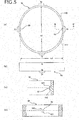
- FIG. 5(a) is a schematic front view of the attachment ring of the air circulator 1 of the first embodiment
- FIG. 5(b) is a schematic side view of the attachment ring
- FIG. 5(c) is a schematic cross-sectional view of the attachment ring when cut along and seen in the directions indicated by the arrows B and FIG.
- FIG. 5(d) is a schematic view of the attachment ring when cut along and seen in the directions indicated by the arrows C.
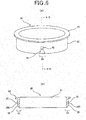
- FIG. 6 (a) is a schematic perspective view of the cylinder unit with flange of the air circulator 1 of the first embodiment and
- FIG. 6(b) is a schematic cross-sectional view of the cylinder unit with flange when cut along and seen in the directions indicated by the arrows D.
- the air circulator 1 of the first embodiment includes a fan main body 10 and an attachment ring (a ring member) 50.
- the fan main body 10 is for realizing the air circulation function which is the original function of the air circulator 1.
- the attachment ring 50 takes a role as a tool exclusively used to attach the fan main body 10 to the sheet member 200.
- the fan main body 10 includes a main body case 14, a motor (not shown) which is built in the main body case, a propeller (wing) 12 which is attached to the rotating shaft of the motor and a connector (not shown) for supplying power to the motor.
- the main body case 14 shown in FIG. 4(a) includes two parts, the upper part and the lower part, and is formed by fitting these parts together.
- the present invention since the present invention relates to a technique to attach the air circulator 1 to the sheet member 200, detailed description on the motor and the propeller 12 will be omitted and the relationship between the main body case 14 and the attachment ring 50 will be mainly described.
- FIG. 4 (a) for the sake of convenience.
- FIGS. 4(b), 4(c) and 4(d) , FIG. 6 , FIG. 7 , FIG. 11(a) and 11(b) and FIGS. 12(a) and 12(b) do not show the entire main body case 14 and only show the cylinder part with flange 20, the first flow unit 15 and the second flow unit 16 being omitted.
- the first flow unit 15 includes a round shaped center base unit 151, a plurality of bar units 152 which extend radially from the center base unit 151 and a ring unit 153 whose center is the center base unit 151. Since the first flow unit 15 has such configuration, the first flow unit 15 allows sufficient air to pass through easily and the outside air can be taken inside when the propeller 12 rotates. Further, the first flow unit 15 also takes up the role as a finger guard which protects fingers from being caught in the rotating propeller 12. The lower part of the first flow unit 15 continues to the cylinder unit with flange 20.
- the cylinder unit with flange 20 includes a flange 22 which is formed in continuation of the bar units 152 of the first flow unit 15 and a hollow cylinder unit 21.
- the cross-section of the cylinder unit 21 when it is cut along the plan surface orthogonal to the center axis thereof is a round shape.
- Concaves (the first engaging units) 25 are formed at predetermined parts of the cylinder unit 21.
- the lower part of the cylinder unit with flange 20 continues to the second flow unit 16.
- the second flow unit 16 includes a plurality of bar units 162, a ring unit 163, a motor fixing unit 164 for fixating the motor and a motor cover 165 which is attached under the motor fixing unit 164.
- the part formed of the plurality of bar units 162 and the ring unit 163 allows sufficient air to pass through easily and this part can protect fingers from being caught in the rotating propeller 12.
- the main body case 14 has such configuration, when the motor fixated to the motor fixing unit 164 rotates and the propeller 12 is made to rotate by the motor, the outside air is taken in through the first flow unit 15 and is let out from the second flow unit 16.
- the present invention relates to a technique to attach the air circulator 1 to the opening formed in the sheet member 200 and the cylinder unit with flange 20 and the attachment ring 50 which are a part of the main body case 14 relate to this technique. Therefore, the cylinder unit with flange 20 will be described more in detail.
- the outer diameter t (the width between two points on the outer surface) of the cylinder unit 21 of the cylinder unit with flange 20 is 90mm as shown in FIG. 4(b) .
- the inner diameter c of the opening 201 formed in the sheet member 200 is 90 to 91mm being the same size or slightly larger than the outer diameter t of the cylinder unit 21 as shown in FIG. 3(a) .
- the flange 22 is formed in a round ring shape and protrudes in the direction approximately orthogonal to the outer surface of the cylinder unit 21 at the upper end of the cylinder unit 21.
- the outer diameter f of the flange 22 is sufficiently larger comparing to the inner diameter c of the opening 201 formed in the sheet member 200 and is 97mm, for example. Furthermore, the outer diameter of the second flow unit 16 is 90mm at the part continuing from the cylinder unit 21 and becomes smaller as approaching the lower part thereof.
- the fan main body 10 can be easily inserted in to the opening 201 formed in the sheet member 200 from above. At this time, the back surface of the flange portion 22 comes in contact with the upper surface of the edge part 202 of the opening 201 (see FIG. 8(a) ).
- the cylinder unit 21 is provided with concaves 25 which are the first engaging units at two predetermined parts of the cylinder unit 21 that are symmetrical with respect to the center axis, that is, at the outside of the two predetermined parts (a pair of the first engaging parts (the first parts) 23) of the cylinder unit 21 that face each other.
- the concaves 25 are for fixating the attachment ring 50 to the fan main body 10.
- the concaves 25 are formed in an approximately square shape when seen from the front and are formed at approximately center of the cylinder unit 21 in the height direction thereof. Further, each of the concaves 25 includes an engaging wall 255 at the lower surface thereof.
- each of the guide inclination units 28 is formed so that the thickness of the cylinder unit 21 be thinner as approaching the lower side thereof.
- the horizontal width of each of the guide inclination units 28 is about the same as the horizontal width of its corresponding concave 25 at the upper side thereof, but the horizontal width of the guide inclination unit 28 becomes wider as approaching the lower side thereof.
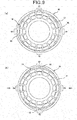
- the attachment ring 50 As shown in FIG. 5(a) , the attachment ring 50 is formed in an oval shape when seen from above (the cross-section shape when the attachment ring 50 is cut along the plan orthogonal to the center axis thereof).
- the attachment ring 50 is provided with protrusions 52 which are the second engaging units on the inner surface thereof at two predetermined parts facing each other in the minor axis direction thereof (a pair of the second engaging parts (the second parts) 53).
- the attachment ring 50 provided with two protrusions 52 is formed as one by the plastic molding. Therefore, the attachment ring 50 has the plasticity characteristic.
- the height of the attachment ring 50 is constant around the entire circumference thereof.
- the protrusions 52 are formed slightly below the center in the height direction of the attachment ring 50.
- Each of the two protrusions 52 is for engaging with its corresponding concave 25 of the fan main body 10 and for fixating the attachment ring 50 to the outside of the cylinder unit 21. Therefore, the positional relationship of the two protrusions 52 is the same as the positional relationship of the two concaves 25.
- each of the protrusions 52 are formed in an approximately quadratic prism shape and protrudes toward inside of the attachment ring 50.
- each of the protrusions 52 includes an engaging wall 522 at the lower surface thereof.
- the lower surfaces themselves of the protrusions 52 correspond to the engaging walls 522. Therefore, the engaging walls 522 are approximately orthogonal to the inner surface of the attachment ring 50.
- each protrusion 52 acts as the engaging wall 522. That is, each protrusion 52 includes the engaging walls 522 at the upper surface and lower surface thereof. Therefore, the upper surface of each protrusion 52 is approximately orthogonal to the inner surface of the attachment ring 50.
- the attachment ring 50 can be used by setting the A side facing up or by setting the B side facing up so that the air circulator 1 can be attached to different types of sheet members 200 having various thicknesses.
- the letters "A” and “B” are marks indicating the direction of the attachment ring 50.
- the attachment ring 50 is attached to the fan main body 10 by setting the "A" side facing up unless mentioned otherwise.
- the width k1 between two points on the inner surface of the attachment ring 50 at the pair of second engaging parts 53 is smaller than the outer diameter t of the cylinder unit 21 and the width k2 between two points on the inner surface of the attachment ring 50 at the pair of pressing parts 54 is larger than the outer diameter t of the cylinder unit 21.
- the cylinder unit 21 is formed in a cylinder shape, both the width between two points on the outer surface of the cylinder unit 21 at the pair of first engaging parts 23 and the width between two points on the outer surface of the cylinder unit at two parts shifted from the pair of first engaging parts by approximately 90 degrees equal to t.
- the width k1 between two points on the inner surface of the attachment ring 50 at the pair of second engaging parts 53 is 88mm and the width k2 between two points on the inner surface of the attachment ring 50 at the pair of pressing parts 54 is 95mm.
- the length of the inner circumference of the attachment ring 50 is longer than the length of the outer circumference of the cylinder unit 21.
- the length of the inner circumference of the attachment ring 50 varies according to the height or the like of the protrusions 52, it is preferred that the length of the inner circumference of the attachment ring 50 is longer than the outer circumference of the cylinder unit 21 by 1.0% to 3.5% of the length of the outer circumference of the cylinder unit 21.
- the length of the inner circumference of the attachment ring 50 is longer than the length of the outer circumference of the cylinder unit 21 by about 2% of the length of the outer circumference of the cylinder unit 21.
- the thickness of the attachment ring 50 is 2mm and its height is slightly lower than the height of the cylinder unit 21. Since the attachment ring 50 is flexible, for example, when the two parts (the pair of pressing parts) 54 where the letters "A" and "B" are indicated are squeezed between a thumb and an index finger, the parts of the attachment ring 50 in the minor axis direction bulge outside and the attachment ring 50 can deform into an approximately circle shape when seen from above. Thereafter, when the squeezing force is released, the attachment ring 50 returns to its original oval shape.
- the attachment ring 50 is attached so as to cover the outer surface of the cylinder unit 21 of the fan main body 10. At this time, the upper end surface of the attachment ring 50 faces the back surface of the flange 22.
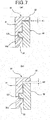
- FIG. 7(a) is a schematic partial cross-sectional view for describing a state where the cylinder unit with flange 20 and the attachment ring 50 are engaged with each other and
- FIG. 7(b) is a schematic partial cross-sectional view for describing a state where the cylinder unit with flange 20 and the attachment ring 50 are engaged with each other where the attachment ring 50 is being set up-side-down.
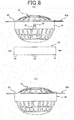
- FIG. 8(a) is a schematic side view for describing the condition where the fan main body 1 is inserted in the opening of the sheet member 200 and
- FIG. 8(b) is a schematic side view for describing the condition where the air circulator 1 is attached to the opening of the sheet member 200.
- the opening 201 for attaching the air circulator 1 is formed in the sheet member 200.
- the opening 201 is formed in a circular shape and the inner diameter c of the opening 201 equals to or is slightly larger than the outer diameter t of the cylinder unit 21 which is formed in a cylinder shape.
- the fan main body 10 is inserted in the opening 201 of the sheet member 200 as shown in FIG. 8(a) and make the back surface of the flange 22 be in contact with the ring-shaped edge part 202 of the sheet member 200 arranged around the opening 201.
- the pair of pressing parts 54 of the attachment ring 50 is held between a thumb and an index finger, for example, and squeezed in the directions indicated by the arrows in FIG. 8(a) to deform the attachment ring 50 into an approximately circle shape. Then, while maintaining the deformed state of the attachment ring 50, the positions of the protrusions 52 of the attachment ring 50 and the positions of the guide inclination units 28 formed at the lower part of the cylinder unit 21 are matched, the attachment ring 50 is fit around the outside of the cylinder unit 21 from below the fan main body 10 and the attachment ring 50 is moved so that the two protrusions 52 are guided along the guide inclination units 28.
- the guide inclination units 28 guides the protrusions 52 when the attachment ring 50 is to be fit around the fan main body 10. Thereafter, when the deformed state of the attachment ring 50 is released and the attachment ring 50 is further moved upward, the protrusions 52 of the attachment ring 50 respectively enter the concaves 25 of the fan main body 10 and the protrusions 52 and the concaves 25 engage with each other. At this time, due to the flexibility of the attachment ring 50, the inner surface of the attachment ring 50 is firmly pressed against the outer surface of the cylinder unit 21 at the areas near the second engaging parts 53.
- the engaging walls 255 and 522 can be formed so that the angles formed by the engaging walls 255 of the concaves 25 and the outer surface of the cylinder unit 21 and the angles formed by the engaging walls 522 of the protrusions 52 and the inner surface of the attachment ring 50 be sharp angles. In such case, the engaging state of the protrusions 52 and the concaves 25 can be made even firmer by the engaging walls 255 and the engaging walls 522 respectively biting into each other.
- the attachment ring 50 being firmly fixated to the fan main body 10 and the attachment ring 50 and the fan main body 10 being as one, as shown in FIG. 8(b) , the ring-shaped edge part 202 of the sheet member 200 around the opening 201 is held between the back surface of the flange 22 and the upper end surface of the attachment ring 50. Therefore, the air circulator 1 can be attached to the sheet member 200 easily and unfailingly.
- the air circulator 1 when the air circulator 1 is attached to the sheet member 200, the upper surface of the ring-shaped edge part 202 of the sheet member 200 comes in contact with the back surface of the flange 22 and the back surface of the ring-shaped edge part 202 of the sheet member 200 comes in contact with the upper end surface of the attachment ring 50. Therefore, the air does not leak from between the flange 22 and the attachment ring 50.
- the air circulator 1 of the first embodiment is designed so that it can be used with various types of sheet members 200 having different thicknesses.
- the protrusions 52 formed on the inner surface of the attachment ring 50 are arranged at positions slightly below the center with respect to the height direction of the attachment ring 50 as shown in FIGS. 5 (c) and 5 (d) .
- the width in the height direction between the upper end surface of the attachment ring 50 and the upper side engaging walls 522 of the protrusions 52 and the width in the height direction between the lower end surface of the attachment ring 50 and the lower side engaging walls 522 of the protrusions 52 are not the same width.
- the letters "A” and "B” are indicated at the pressing parts 54. Since the height of the attachment ring 50 is constant around the entire circumference thereof, the attachment ring 50 can be used by setting either side, the "A" side or the "B" side, facing up.
- FIG. 7 (a) shows the engaging state of the cylinder unit with flange 20 and the attachment ring 50 when the attachment ring 50 is used by setting the "A" side facing up
- FIG. 7(b) shows the engaging state of the cylinder unit with flange 20 and the attachment ring 50 when the attachment ring 50 is used by setting the "B" side facing up.
- the attachment ring 50 is used by setting the "B" side facing up, the space s2 between the back surface of the flange 22 and the upper end surface of the attachment ring 50 which is formed when the protrusions 52 and the concaves 25 are engaged with each other is large as shown in FIG. 7 (b) . Therefore, such method of using the attachment ring 50 is suited to the case where the sheet member 200 is a thick material. In such way, the air circulator 1 of the first embodiment can be used with various types of sheet members 200 having different thicknesses.
- the air circulator 1 of the first embodiment can be used with various types of sheet members 200 having different thicknesses.
- the space between the back surface of the flange 22 and the upper end surface of the attachment ring 50 should be different according to which side, the upper side or the lower side, of the attachment ring 50 is set to face up when the attachment ring 50 is attached to the fan main body 10. Therefore, the positions of the first engaging units with respect to the height direction of the cylinder unit 21 and the positions of the second engaging units with respect to the height direction of the attachment ring 50 can be designed to be formed at different positions.
- FIG. 9(a) is a schematic back side view of the fan main body 10 to which the attachment ring 50 is attached and
- FIG. 9 (b) is a schematic back side view for describing a state where the pair of pressing parts 54 of the attachment ring 50 of the fan main body 10 are squeezed toward the center.
- the attachment ring 50 is formed in an oval shape where the width k1 between two points on the inner surface of the attachment ring 50 at the pair of second engaging parts 53 is smaller than the outer diameter t of the cylinder unit 21 of the fan main body 10, the width k2 between two points on the inner surface of the attachment ring 50 at the pair of pressing parts 54 is larger than the outer diameter t of the cylinder unit 21 of the fan main body 10 and the length of the inner circumference of the attachment ring 50 is longer then the length of the outer circumference of the cylinder unit 21 by about 2% of the length of the outer circumference of the cylinder unit 21.
- the inner surface of the attachment ring 50 is in contact with the outer surface of the cylinder unit 21 at the areas near the pair of second engaging parts 53 as shown in FIG. 9(a) .
- the inner surface of the attachment ring 50 is not in contact with the outer surface of the cylinder unit 21 at the areas near the pair of pressing parts 54 and spaces 80 are formed between the inner surface of the attachment ring 50 and the outer surface of the cylinder unit 21.
- the two pressing parts 54 are squeezed in the directions shown by the arrows in FIG. 9(b) .
- the pair of pressing parts 54 of the attachment ring 50 is held between a thumb and an index finger, for example, and squeezed so that the inner surfaces of the pressing parts come in contact with the outer surface of the cylinder unit 21 of the fan main body 10.
- the areas near the pair of second engaging parts 53 of the attachment ring 50 bulge and the engaging state of the protrusions 52 and the concaves 25 is released.
- the attachment ring 50 is pulled downward from the fan main body 10. In such way, the attachment ring 50 can be easily detached from the fan main body 10.
- the engaging state of the one side can be released first and then the engaging state of the other side can be released later instead of releasing the engaging state of both sides at the same time by squeezing the pair of pressing parts 54 of the attachment ring 50. If the attachment ring 50 is to be detached by such method, there is no need to make the inner circumference of the attachment ring 50 be larger than the outer circumference of the cylinder unit 21 by a great extent.
- the fan main body is placed so that the back surface of the flange of the fan main body comes in contact with the ring-shaped edge part of the sheet member, the positions of the concaves of the fan main body and the positions of the protrusions of the attachment ring are matched, the attachment ring is fit around the cylinder unit of the fan main body from below the fan main body by utilizing the flexibility of the attachment ring and the concaves of the fan main body and the protrusions of the attachment ring are engaged with each other and thereby, the attachment ring can be easily attached and firmly fixated to the fan main body.
- the ring-shaped edge part of the sheet member is held between the back surface of the flange of the fan main body and the upper end surface of the attachment ring and thereby, as a result, the air circulator can be firmly attached to the sheet member.
- the pair of pressing parts is squeezed so that the inner surfaces of the pressing parts come in contact with the outer surface of the cylinder unit of the fan main body by utilizing the flexibility of the attachment ring to deform the attachment ring and thereby, the areas near the pair of second engaging parts of the attachment ring bulge and the engaging state of the concaves of the fan main body and the protrusions of the attachment ring can be easily released.
- the attachment ring can be easily detached from the fan main body and the fan main body can be easily detached from the sheet member.
- the air circulator of the first embodiment has a simple configuration and a user can easily attach and detach the air circulator to and from the sheet member.
- the length of the inner circumference of the attachment ring is longer than the length of the outer circumference of the cylinder unit by 1.0% to 3.5% of the length of the outer circumference of the cylinder unit. Therefore, the attachment ring can be smoothly attached to and detached from the fan main body.
- the guide inclination units for guiding the protrusions of the attachment ring when fitting the attachment ring on the fan main body are formed at the pair of first engaging parts of the cylinder unit. Therefore, the protrusions of the attachment ring can be guided to the concaves of the fan main body and the attachment ring can be smoothly attached to the fan main body.
- each of the protrusions include the engaging walls at the upper surface and the lower surface thereof, the width in the height direction between the upper end surface of the attachment ring and the upper side engaging walls of the protrusions and the width in the height direction between the lower end surface of the attachment ring and the lower side engaging walls of the protrusions are not equal to each other, and the space between the back surface of the flange and the end surface of the attachment ring that faces the back surface of the flange formed when the attachment ring is fit around the fan main body in the normal direction and the concaves and the protrusions are engaged with each other and the space between the back surface of the flange and the end surface of the attachment ring that faces the back surface of the flange formed when the attachment ring is fit around the fan main body up-side-down and the concaves and protrusions are engaged with each other are not equal to each other. Therefore, by using the attachment ring by setting either sides
- each of the protrusions of the attachment ring is provided with the engaging walls at the upper surface and the lower surface thereof so that the attachment ring can be used either way, the upper side thereof facing up or the lower side thereof facing up, is described.
- each of the protrusions of the attachment ring is provided with only the lower surface engaging wall.
- the attachment ring can be attached more smoothly.
- the width k1 between two points on the inner surface of the attachment ring 50 at the pair of second engaging parts 53 is smaller than the outer diameter t of the cylinder unit 21 is described.
- the width k1 between two points on the inner surface of the attachment ring 50 at the pair of second engaging parts 53 may be equal to the outer diameter t of the cylinder unit 21. This is because if the inner surface of the attachment ring 50 comes in contact with the outer surface of the cylinder unit 21 at the areas near the pair of second engaging parts 53, the attachment ring 50 and the fan main body 10 will be firmly fixated to each other.
- the parts of the outside corner at the end parts of the attachment ring 50 on the pressing part 54 sides, the pressing parts 54 forming a pair, and on the side that faces the flange 22 is chamfered.
- the air circulator 1 presses against the sheet member 200 and the sheet member 200 bends at the corner of the attachment ring 50 if a force toward outside is applied to the air circulator 1 from inside of the sheet member 200 for some reason and the attachment ring 50 receives a force toward the center thereof due to the sheet member 200 bending.
- FIG. 10 shows the force which the attachment ring 50 receives due to the sheet member 200 bending.
- the attachment ring 50 of the embodiment is formed in an oval shape when seen from above, the pair of pressing parts (the parts facing each other in the long axis direction) 54 of the attachment ring 50 receives a force that is greater comparing to the force which the pair of second engaging parts (the parts facing each other in the short axis direction) 53 receives. Therefore, the pair of pressing parts 54 may be pushed inside and the attachment ring 50 may deform into a circle shape causing the attachment ring 50 to fall off from the fan main body.
- FIG. 11(a) is a schematic plan view of the attachment ring 50 to which chamfering is carried out and FIG.
- FIG. 11 (b) is a view for describing a state where the air circulator 1 is attached to the sheet member 200 by using the attachment ring 50 to which chamfering is carried out.
- the outer edge parts of the attachment ring 50 at the pair of pressing parts 54 and the surrounding areas thereof on the upper end side of the attachment ring 50 are the parts (chamfered parts) 541 where chamfering is carried out.
- the predetermined parts of the attachment ring 50 are chamfered by cutting off the parts so as to form plan surfaces in the example shown in FIG. 11 , in general, the predetermined parts of the attachment ring 50 may be chamfered by cutting off the parts so as to form curved surfaces.
- the parts of the outside corner at the end parts of the attachment ring on the pressing part sides, the pressing parts forming a pair, and on the side that faces the flange be chamfered not only in the air circulator of the first embodiment but also in the air circulators of various embodiments which will be described later.
- first engaging units are the concaves 25 which are formed on the outer surface of the cylinder unit 21 at the pair of first engaging parts 23 and the second engaging units are the protrusions 52 which are formed on the inner surface of the attachment ring 50 at the pair of second engaging parts 53 is described.
- protrusions are used as the first engaging units instead of concaves and concaves are used as the second engaging units instead of protrusions.
- the rest of the configuration is the same as the configuration of the first embodiment described above. Therefore, the detail description will be omitted here.
- the upper surfaces of the protrusions which are the first engaging units are the engaging walls and the upper surfaces of the concaves which are the second engaging units are the engaging walls .
- the guide inclination units are formed at the pair of first engaging parts 23.
- the guide inclination units are formed at the pair of second engaging parts where protrusions are not formed.
- the air circulator of the modification example operates in the same way as the air circulator of the first embodiment. That is, the attachment procedure and the detachment procedure of the air circulator are exactly the same as the procedures described in the first embodiment. Therefore, the air circulator of the modification example has the same advantages as those of the first embodiment.
- the concaves as the second engaging units may be through holes.
- FIG. 12 (a) is a schematic back side view of the fan main body of the air circulator of the second embodiment and FIG. 12 (b) is a schematic front view of the attachment ring of the air circulator of the second embodiment.
- the cross-section of the cylinder unit of the fan main body when cut along the plan surface orthogonal to the center axis thereof is a circle shape.
- the cross-section of the cylinder unit 21a of the fan main body 10a when cut along the plan surface orthogonal to the center axis thereof is an approximately rectangular shape, for example.
- Concaves as the first engaging units are formed on the outer surface of the cylinder unit 21a at the pair of first engaging parts 23, the first engaging parts 23 facing each other. In such case, as shown in FIG.
- the attachment ring 50a is also formed so that the cross-section of the attachment ring 50a when cut along a plan surface orthogonal to the center axis thereof be an approximately rectangular shape corresponding to the shape of the cylinder unit 21a of the fan main body 10a.
- the protrusions 52a as the second engaging units which engage with the first engaging units are formed on the inner surface of the attachment ring 50a at the pair of second engaging parts 53, the second engaging parts 53 facing each other.
- the areas near the protrusions 52a of the attachment ring 50a are curved inside and the width k1 between two point on the inner surface of the attachment ring 50a at the pair of second engaging parts 53 is slightly smaller comparing to the width t1 between two points on the outer surface of the cylinder unit 21a at the pair of first engaging parts 23.
- the two sides of the attachment ring 50a which face each other and which do not include the second engaging parts 53 are formed so as to slightly bulge toward outside. Therefore, similarly to the first embodiment, the areas near the pair of second engaging parts 53 will bulge outside when the two sides of the attachment ring 50a (a pair of pressing parts) that bulge toward outside are squeezed in the second embodiment.
- the air circulator of the second embodiment has the function and advantages similar to those in the case of the above described first embodiment and a user can easily attach and detach the air circulator to and from the sheet member.
- the rest of the configuration of the second embodiment is the same as that of the above described first embodiment. Therefore, the detail description thereof is omitted here.
- FIG. 13(a) is a schematic perspective view of the cylinder unit with flange of the air circulator of the third embodiment
- FIG. 13(b) is a schematic cross-sectional view of the cylinder unit with flange when cut along and seen in the directions indicated by the arrows E
- FIG. 13 (c) is a schematic front view of the attachment ring of the air circulator of the third embodiment
- FIG. 13 (d) is a schematic cross-sectional view of the attachment ring when cut along and seen in the directions indicated by the arrows F.
- the cylinder unit 21 extends downward at the pair of first engaging parts 23.
- the protrusions 26 as the first engaging units are formed on the outer surfaces of the extended parts.
- the upper surfaces of the protrusions 26 are the engaging walls 255a.
- the inclination unit 61a for smoothly fitting the attachment ring is formed at the lower parts of the protrusions 26.
- the second engaging units are not formed at the pair of second engaging parts 53 of the attachment ring 50 and the inclination units 61b for smoothly fitting the attachment ring 50 are formed at the upper end part of the attachment ring 50 at the pair of second engaging parts 53.
- the pair of pressing parts 54 are squeezed, the positions of the inclination units 61a formed on the cylinder unit 21 and the positions of the inclination units 61b formed on the attachment ring 50 are matched and the attachment ring 50 is fit around the cylinder unit 21 from below the fan main body and thereby, the attachment ring 50 is attached to the fan main body.
- the engaging walls 255a of the cylinder unit 21 and the lower end surface of the attachment ring 50 engage with each other. That is, in such case, the parts of the lower end surface of the attachment ring 50 at the pair of second engaging parts 53 act as the engaging walls 522a and they can be assumed as being the second engaging units. In such way, by the engaging walls 255a of the cylinder unit 21 and the lower end surface 522a of the attachment ring 50 engaging with each other, the attachment ring 50 will not fall off from the fan main body even if an outer force is applied to the air circulator.
- small concaves (rotation stoppers) 62a are formed on the outer surface of the cylinder unit 21 at the pair of first engaging parts 23 and small protrusions (rotation stoppers) 62b are formed on the attachment ring 50 at the parts corresponding to the concaves 62a so that the two sets of the rotation stoppers 62a and 62b engage with each other when the attachment ring 50 is attached to the fan main body. In such way, the attachment ring 50 can be prevented from rotating with respect to the cylinder unit 21.
- the air circulator of the third embodiment has such configuration, it has the function and the advantages similar to those of the first embodiment and a user can easily and unfailingly attach the air circulator to the sheet member and easily detach the air circulator from the sheet member.
- the rest of the configuration of the third embodiment is the same as that of the above described first embodiment. Therefore, the detailed description thereof is omitted here.
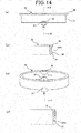
- FIG. 14(a) is a schematic side view of the cylinder unit with flange of the air circulator of the four embodiment
- FIG. 14(b) is a schematic cross-sectional view of the cylinder unit with flange when cut along and seen in the directions indicated by the arrows G
- FIG. 14 (c) is a schematic perspective view of the attachment ring of the air circulator of the fourth embodiment
- FIG. 14(d) is a schematic cross-sectional view of the attachment ring when cut along and seen in the directions indicated by the arrows H.
- the cylinder unit is extended downward at the pair of first engaging parts and the protrusions as the engaging units are formed on the outer surfaces of the extended parts.
- the cylinder unit 21 is not extended downward at the pair of first engaging parts 23 and the protrusions 26 as the first engaging units are formed on the outer surface of the cylinder unit 21 at the lower end part thereof.
- the upper surfaces of the protrusions 26 are the engaging walls 255b. Therefore, the engaging walls 255b are positioned slightly above the lower end surface of the cylinder unit 21.
- FIGS. 14 (a) and 14 (b) the cylinder unit 21 is not extended downward at the pair of first engaging parts 23 and the protrusions 26 as the first engaging units are formed on the outer surface of the cylinder unit 21 at the lower end part thereof.
- the upper surfaces of the protrusions 26 are the engaging walls 255b. Therefore, the engaging walls 255b are positioned slightly above the lower end surface of the cylinder unit 21.
- the cutouts 57 are formed at the lower end part of the attachment ring 50 at the pair of second engaging parts 53 so as to correspond to the protrusions 26 formed on the cylinder unit 21.
- the cutouts 57 are the second engaging units and the upper surfaces of the cutout portions of the attachment ring 50 are the engaging walls 522b.
- the guide inclination units 58 for guiding the protrusions 26 are formed on the inner surface of the attachment ring 50 at the upper end part at the pair of second engaging parts 53.
- the air circulator of the fourth embodiment has such configuration, it has the function and the advantages similar to those of the third embodiment and a user can easily and unfailingly attach the air circulator to the sheet member and easily detach the air circulator from the sheet member.
- the rest of the configuration of the fourth embodiment is the same as that of the above described third embodiment. Therefore, the detailed description thereof is omitted here.
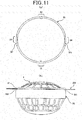
- FIG. 15(a) is a schematic plan view of the attachment ring of the air circulator of the fifth embodiment
- FIG. 15 (b) is a schematic side view of the attachment ring
- FIG. 15 (c) is a schematic back side view of the air circulator of the fifth embodiment.
- the parts of the outside corner at the end parts of the attachment ring on the pressing part sides, the pressing parts forming a pair, and on the side that face the flange are chamfered.
- the method for preventing the attachment ring from falling off from the fan main body due to the force caused by the bending of the sheet member is not limited to the above described method of chamfering and for example, with respect each of the second engaging parts that form a pair, a plurality of protrusions can be formed at the part on the outer surface of the attachment ring corresponding to the second engaging part and the area nearby.
- the air circulator of the fifth embodiment is made by applying the method of forming, with respect to each of the second engaging parts that form a pair, a plurality of protrusions at the part on the outer surface of the attachment ring corresponding to the second engaging part and the area nearby.
- one protrusion may be formed on the outer surface of the attachment ring 50 at the position corresponding to the second engaging part 53 and nearby.
- the thickness of the attachment ring 50 be thick in the areas corresponding to the second engaging parts 53 and the attachment ring 50 cannot deform easily even when the attachment ring 50 is held by the pair of pressing parts 54 and squeezed. Therefore, it is preferred that a plurality of protrusions having small width, for example, three small protrusions be formed at each of the second engaging parts that form a pair as shown in FIG. 15 (total of 6 protrusions), so that the attachment ring 50 can easily deform.
- the air circulator of the fifth embodiment has the function and the advantages similar to those of the first embodiment.
- three protrusions are formed on the outer surface of the attachment ring at the part corresponding to the second engaging part and nearby to make the shape of the attachment ring which come in contact with the sheet member substantially become close to a circle shape. Therefore, any part of the attachment ring equally receives the same amount of force even if a force toward outside is applied to the air circulator from inside of the sheet member for some reason and thus, the attachment ring 50 can be prevented from falling off.
- the method of forming, with respect to each of the engaging parts that form a pair, one or a plurality of protrusions on the outer surface of the attachment ring at the part corresponding to the second engaging part and nearby applied in the air circulator of the fifth embodiment can be applied to the air circulators of various embodiments.
- the flange can be formed on the cylinder unit so as to protrude from the outer surface of the cylinder unit in the direction approximately orthogonal to the outer surface of the cylinder unit.
- the flange can be formed at approximately center of the cylinder unit instead of forming it at the upper end of the cylinder unit.
- the air circulator of the present invention is applied to an air circulation-type mat for chair.
- the air circulator of the present invention can be applied to various types of devices which make the air circulate inside thereof such as air conditioned outer wears, for example, and not limited to the air circulation-type mat.
- the fan main body is placed so that the back surface of the flange of the fan main body come in contact with the edge part of the sheet member around the opening formed in the sheet member, the positions of the first engaging units of the fan main body and the positions of the second engaging units of the ring member are matched, the ring member is fit around the outside of the cylinder unit of the fan main body from below the fan main body by utilizing the flexibility of the ring member and the first engaging units of the fan main body and the second engaging units of the ring member are engaged with each other and thereby, the ring member can be easily attach and firmly fixate to the fan main body.
- the edge part of the sheet member around the opening formed in the sheet member is held between the back surface of the flange of the fan main body and one end surface of the ring member and thereby, as a result, the air circulator can be firmly attached to the sheet member.
- the ring member is held by the pair of pressing parts between a thumb and an index finger, for example, and the pair of pressing parts are squeezed so that the inner surfaces of the pressing parts come in contact with the outer surface of the cylinder unit of the fan main body by utilizing the flexibility of the ring member.
- the air circulator of the present invention has a simple configuration and a user can easily attach and detach the air circulator to and from the sheet member. Therefore, the air circulator of the present invention can be used in air circulation-type mats, air conditioned outer wears and the like which function by circulating the air inside thereof, for example.
Landscapes
- Engineering & Computer Science (AREA)
- Mechanical Engineering (AREA)
- General Engineering & Computer Science (AREA)
- Environmental & Geological Engineering (AREA)
- Health & Medical Sciences (AREA)
- General Health & Medical Sciences (AREA)
- Physical Education & Sports Medicine (AREA)
- Textile Engineering (AREA)
- Structures Of Non-Positive Displacement Pumps (AREA)
- Professional, Industrial, Or Sporting Protective Garments (AREA)
Claims (15)
- Luftzirkulator (1), der an einer Öffnung (201) in einem Lagenelement (200) anbringbar ist und der zur Erzeugung eines Luftstroms von einer Seite des Lagenelements (200) zu einer anderen Seite des Lagenelements (200) dient, umfassend:einen Gebläsehauptkörper (10, 10a) undein Ringelement (50, 50a) zum Anbringen des Gebläsehauptkörpers (10, 10a) an dem Lagenelement (200), wobeider Gebläsehauptkörper (10, 10a) umfasst:eine Hohlzylindereinheit (21);einen Flansch (22), der an der Zylindereinheit (21) so ausgebildet ist, dass er von einer Außenfläche der Zylindereinheit (21) in einer Richtung annähernd orthogonal zur Außenfläche der Zylindereinheit (21) vorsteht;eine Motorbefestigungseinheit (164) zum Befestigen eines Motors;einen Motor, der an der Motorbefestigungseinheit befestigt ist;einen Flügel (16), der an einer Drehwelle des Motors angebracht ist; underste Eingriffseinheiten (25, 26), die an Außenflächen von ersten Teilen (23) der Zylindereinheit (21) ausgebildet sind, wobei die ersten Teile (23) ein Paar bilden und einander zugewandt sind,wobei das Ringelement (50, 50a) umfasst:
zweite Eingriffseinheiten (52, 52a, 57), die an Innenflächen von zweiten Teilen (53) des Ringelements (50, 50a) ausgebildet sind, wobei die zweiten Teile (53) ein Paar bilden und einander zugewandt sind, und die konfiguriert sind, um mit den ersten Eingriffseinheiten (25, 26) in Eingriff zu kommen,wobei eine Breite zwischen zwei Punkten an einer Innenfläche des Ringelements (50, 50a) an den zweiten Teilen (53), die ein Paar bilden, gleich einer Breite zwischen zwei Punkten an der Außenfläche der Zylindereinheit (21) an den ersten Teilen (23) ist, die ein Paar bilden, oder kleiner ist als die Breite zwischen den beiden Punkten an der Außenfläche der Zylindereinheit (21) an den ersten Teilen (23), die ein Paar bilden,eine Breite zwischen zwei Punkten an der Innenfläche des Ringelements (50, 50a) an einem Paar von Druckteilen (54), wobei die Druckteile (54) zwei Teile sind, die von den zweiten Teilen (53), die ein Paar bilden, um annähernd 90 Grad versetzt sind, größer ist als eine Breite zwischen zwei Punkten an der Außenfläche der Zylindereinheit (21) an zwei Teilen, die von den ersten Teilen (23), die ein Paar bilden, um annähernd 90 Grad versetzt sind, und ein innerer Umfang des Ringelements (50, 50a) größer ist als ein äußerer Umfang der Zylindereinheit (21),dadurch gekennzeichnet, dassdas Ringelement (50, 50a) flexibel ist, so dass:durch Anpassen des Ringelements (50, 50a) um die Außenfläche der Zylindereinheit (21) unter Nutzung der Flexibilität des Ringelements (50, 50a), so dass ein Randteil der in dem Lagenelement (200) ausgebildeten Öffnung (201) zwischen einer Rückfläche des Flansches (22) des Gebläsehauptkörpers (10, 10a) und einer Endfläche des Ringelements (50, 50a) gehalten wird, und die ersten Eingriffseinheiten (25, 26) und die zweiten Eingriffseinheiten (52, 52a, 57) miteinander in Eingriff kommen, der Gebläsehauptkörper (10, 10a) an dem Lagenelement (200) angebracht werden kann, unddurch Quetschen des Paares von Druckteilen (54) des Ringelements (50, 50a), so dass das Ringelement (50, 50a) gebogen wird, der Eingriff der ersten Eingriffseinheiten (25, 26) und der zweiten Eingriffseinheit (52, 52a, 57) freigegeben wird und der Gebläsehauptkörper (10, 10a) von dem Lagenelement (200) gelöst werden kann. - Luftzirkulator (1) nach Anspruch 1, wobei das Ringelement (50) einen oder mehrere Vorsprünge (531) umfasst, die mit Bezug auf jedes der zweiten Teile (53), die ein Paar bilden, an einer Außenfläche des Ringelements (50) an einem Teil entsprechend dem zweiten Teil (53) ausgebildet sind.
- Luftzirkulator (1) nach Anspruch 2, wobeider eine oder die mehreren Vorsprünge (531) zwei Punkte (531) aufweisen, die mit Bezug auf einen Mittelpunkt des Ringelements (50) symmetrisch sind, undeine Breite (k3) zwischen den beiden Punkten an Außenflächen der beiden Vorsprünge (531) annähernd gleich einer Breite (k4) zwischen zwei Punkten an der Außenfläche des Ringelements (50) an dem Paar von Druckteilen (54) ist.
- Luftzirkulator (1) nach Anspruch 1, wobei das Ringelement (50) Teile (541) einer äußeren Ecke an Endteilen des Ringelements (50) an den Seiten des Druckteils (54) und an einer Seite umfasst, die dem Flansch (22) zugewandt ist, wobei diese Teile (541) abgeschrägt sind.
- Luftzirkulator nach einem der Ansprüche 1 bis 4, wobei der Innere Umfang des Ringelements (50) um 1,0 % bis 3,5 % des äußeren Umfangs der Zylindereinheit (21) länger ist als der äußere Umfang der Zylindereinheit (21).
- Luftzirkulator nach einem der Ansprüche 1 bis 5, wobeidie ersten Eingriffseinheiten Höhlungen (25) mit Eingriffswänden (255) an unteren Flächen davon sind, die an der Außenfläche der Zylindereinheit (21) an den ersten Teilen (23), die ein Paar bilden, ausgebildet sind, unddie zweiten Eingriffseinheiten Vorsprünge (52) mit Eingriffswänden an unteren Flächen davon sind, die an der Innenfläche des Ringelements (50) an den zweiten Teilen (53), die ein Paar bilden, ausgebildet sind.
- Luftzirkulator nach Anspruch 6, wobei Führungsneigungseinheiten (28) zum Führen der zweiten Eingriffseinheiten, die Vorsprünge (52) sind, wenn das Ringelement (50) um den Gebläsehauptkörper (10) angepasst ist, an den ersten Teilen (23), die ein Paar bilden, ausgebildet sind.
- Luftzirkulator nach einem der Ansprüche 1 bis 5, wobeidie ersten Eingriffseinheiten Vorsprünge (26) mit Eingriffswänden (255a) an oberen Flächen davon sind, die an den Außenflächen der Zylindereinheit an den ersten Teilen (23), die ein Paar bilden, ausgebildet sind, unddie zweiten Eingriffseinheiten Höhlungen (57) mit Eingriffswänden (522b) an oberen Flächen davon sind, die an der Innenfläche des Ringelements (50) an den zweiten Teilen (53), die ein Paar bilden, ausgebildet sind.
- Luftzirkulator nach Anspruch 8, wobei Führungsneigungseinheiten (58) zum Führen der ersten Eingriffseinheiten, die Vorsprünge (26) sind, wenn das Ringelement um den Gebläsehauptkörper angepasst ist, an den zweiten Teilen (53), die ein Paar bilden, ausgebildet sind.
- Luftzirkulator (1) nach einem der Ansprüche 6 bis 9, wobeieine Höhe des Ringelements (50) über dessen gesamten Umfang konstant ist, wobei jede der zweiten Eingriffseinheiten (52) die Eingriffswände (522) an einer oberen und einer unteren Fläche davon aufweist,ein Zwischenraum in einer Höhenrichtung zwischen der oberen Endfläche des Ringelements (50) und der Eingriffswand (522) an der oberen Fläche der zweiten Eingriffseinheit (52) und ein Zwischenraum in der Höhenrichtung zwischen der unteren Endfläche des Ringelements (50) und der Eingriffswand an der unteren Fläche der zweiten Eingriffseinheit (52) zueinander nicht gleich sind,die ersten Eingriffseinheiten und die zweiten Eingriffseinheiten so konfiguriert sind, dass sie in einem Zustand miteinander in Eingriff kommen, in dem das Ringelement in einer senkrechten Richtung um den Gebläsehauptkörper angepasst ist,die ersten Eingriffseinheiten und die zweiten Eingriffseinheiten so konfiguriert sind, dass sie in einem Zustand miteinander in Eingriff kommen, in dem das Ringelement in einer umgekehrten Richtung um den Gebläsehauptkörper angepasst ist, undein Zwischenraum (s1) zwischen der Rückseite des Flansches (22) und einer Endfläche des Ringelements, die der Rückseite des Flansches (22) in dem Zustand zugewandt ist, in dem das Ringelement um den Gebläsehauptkörper in der senkrechten Richtung angepasst ist, und ein Zwischenraum (s2) zwischen der Rückseite des Flansches und der Endfläche des Ringelements, die der Rückseite des Flansches in dem Zustand zugewandt ist, in dem das Ringelement um den Gebläsehauptkörper in der umgekehrten Richtung angebracht ist, zueinander nicht gleich sind.
- Luftzirkulator nach einem der Ansprüche 1 bis 5, wobeidie ersten Eingriffseinheiten Vorsprünge (26) sind, die an Außenflächen von Teilen der Zylindereinheit (21) ausgebildet sind, die sich an den ersten Teilen (23), die ein Paar bilden, nach unten erstrecken, unddie zweiten Eingriffseinheiten Teile einer unteren Endfläche (522a) des Ringelements (50) an den zweiten Teilen (53) sind, die ein Paar bilden.
- Luftzirkulator (1) nach Anspruch 11, wobeiNeigungseinheiten (61a) zum gleichmäßigen Einpassen des Ringelements (50) an den unteren Teilen der ersten Eingriffseinheiten, die Vorsprünge (26) sind, ausgebildet sind,die oberen Flächen der ersten Eingriffseinheiten, die Vorsprünge (26) sind, Eingriffswände (255a) sind,Neigungseinheiten (61b) zum gleichmäßigen Einpassen des Ringelements (50) am oberen Endteil des Ringelements (50) an den zweiten Teilen (53), die ein Paar bilden, ausgebildet sind,kleine Höhlungen (62a) an der Außenfläche der Zylindereinheit (21) ausgebildet sind,kleine Vorsprünge (62b) an der Innenfläche des Ringelements (50) ausgebildet sind unddie kleinen Höhlungen (62a) und die kleinen Vorsprünge (62b) miteinander in Eingriff kommen.
- Luftzirkulator nach einem der Ansprüche 1 bis 5, wobei die ersten Eingriffseinheiten Vorsprünge (26) mit Eingriffswänden (255a) an oberen Flächen davon sind, die an der Außenfläche der Zylindereinheit (21) am unteren Endteil an den ersten Teilen (23), die ein Paar bilden, ausgebildet sind, und
die zweiten Eingriffseinheiten Ausnehmungen (57) sind, die am unteren Endteil des Ringelements (50) an den zweiten Teilen (53), die ein Paar bilden, ausgebildet sind. - Luftzirkulator (1) nach einem der Ansprüche 1 bis 13, wobei ein Querschnitt der Zylindereinheit (21), wenn er entlang einer Ebene orthogonal zu einer Mittelachse davon geschnitten wird, eine Kreisform ist, und ein Querschnitt des Ringelements (50), wenn er entlang einer Ebene orthogonal zu einer Mittelachse davon geschnitten wird, eine ovale Form ist.
- Luftzirkulator (1) nach einem der Ansprüche 1 bis 13, wobei jeder der Querschnitte der Zylindereinheit (21) und des Ringelements (50a), wenn sie entlang einer Ebene orthogonal zu einer Mittelachse davon geschnitten werden, eine annähernd rechteckige Form hat.
Applications Claiming Priority (1)
| Application Number | Priority Date | Filing Date | Title |
|---|---|---|---|
| PCT/JP2014/078364 WO2016063416A1 (ja) | 2014-10-24 | 2014-10-24 | 送風装置 |
Publications (3)
| Publication Number | Publication Date |
|---|---|
| EP3211246A1 EP3211246A1 (de) | 2017-08-30 |
| EP3211246A4 EP3211246A4 (de) | 2018-05-23 |
| EP3211246B1 true EP3211246B1 (de) | 2021-10-13 |
Family
ID=55760483
Family Applications (1)
| Application Number | Title | Priority Date | Filing Date |
|---|---|---|---|
| EP14904425.7A Active EP3211246B1 (de) | 2014-10-24 | 2014-10-24 | Luftausblasvorrichtung |
Country Status (6)
| Country | Link |
|---|---|
| US (1) | US10760591B2 (de) |
| EP (1) | EP3211246B1 (de) |
| JP (1) | JP6374524B2 (de) |
| CN (1) | CN107076169B (de) |
| ES (1) | ES2902206T3 (de) |
| WO (1) | WO2016063416A1 (de) |
Families Citing this family (12)
| Publication number | Priority date | Publication date | Assignee | Title |
|---|---|---|---|---|
| JP6851206B2 (ja) * | 2017-01-20 | 2021-03-31 | 株式会社マキタ | 送風装置および衣服 |
| JP6473558B2 (ja) * | 2017-08-14 | 2019-02-20 | 京セラインダストリアルツールズ株式会社 | 衣服用ファン及びファン付き衣服 |
| JP6951161B2 (ja) * | 2017-09-08 | 2021-10-20 | 京セラインダストリアルツールズ株式会社 | 衣服用ファン及びファン付き衣服 |
| CN108930660B (zh) * | 2018-07-18 | 2020-11-13 | 杭州新融方科技有限公司 | 一种基于物联网的低噪声智能管道风机及其操作方法 |
| JP7251754B2 (ja) * | 2018-11-12 | 2023-04-04 | 株式会社セフト研究所 | ファン取付孔の蓋、衣服及び空調衣服 |
| EP3670316A1 (de) * | 2018-12-17 | 2020-06-24 | Elomatic Oy | Gitter für ein tunnelstrahlruder |
| JP6631981B2 (ja) * | 2019-01-22 | 2020-01-15 | 株式会社マキタ | 送風装置および衣服 |
| KR102181188B1 (ko) * | 2019-02-26 | 2020-11-20 | 이호영 | 휴대용 선풍기 및 휴대용 선풍기가 결합된 공기청정기 |
| JP2021070885A (ja) * | 2019-10-31 | 2021-05-06 | 株式会社セフト研究所 | 空調衣服の服本体及び空調衣服 |
| JP7339228B2 (ja) * | 2020-11-10 | 2023-09-05 | トヨタ自動車株式会社 | 空調衣服 |
| JP7495773B1 (ja) | 2024-02-27 | 2024-06-05 | セーフラン安全用品株式会社 | 送排風機取付部付き石綿除去作業用防護服 |
| WO2025243937A1 (ja) * | 2024-05-22 | 2025-11-27 | 株式会社セフト研究所 | ファン、ファン付きウェアの服本体及びファン付きウェア |
Family Cites Families (18)
| Publication number | Priority date | Publication date | Assignee | Title |
|---|---|---|---|---|
| GB1166469A (en) * | 1966-12-16 | 1969-10-08 | Colchester Woods | Improvements in or relating to Extractor Fans |
| JPS5865004A (ja) * | 1981-10-12 | 1983-04-18 | 西尾 幸良 | 冷却服 |
| US5610877A (en) * | 1995-01-20 | 1997-03-11 | Adams; Kathy S. | Fabric attachable timepiece |
| CA2338970A1 (en) * | 1998-07-30 | 2000-02-10 | Seft Development Laboratory Co., Ltd. | Cooling pillow, cooling clothes and cooling helmet |
| DE29902125U1 (de) | 1999-02-09 | 1999-04-08 | Gertz, Brigitte, 73230 Kirchheim | Armbanduhr |
| US6719534B2 (en) | 2001-04-11 | 2004-04-13 | Denso Corporation | Vehicle seat blower unit with a motor mounted within a scroll housing and a cooling motor attachment bracket |
| JP2002370517A (ja) | 2001-04-11 | 2002-12-24 | Denso Corp | 車両用送風装置 |
| CN2590551Y (zh) * | 2002-06-01 | 2003-12-10 | 戴振华 | 降温衣 |
| JP4399765B2 (ja) * | 2003-06-26 | 2010-01-20 | 株式会社セフト研究所 | ファン露出型空調服用のファン取付装置及びファン露出型空調服用の送風装置 |
| JPWO2006009108A1 (ja) | 2004-07-21 | 2008-05-01 | 株式会社セフト研究所 | 空調衣服 |
| WO2006098429A1 (ja) * | 2005-03-17 | 2006-09-21 | Seft Development Laboratory Co., Ltd. | 空調衣服 |
| TWI322230B (en) * | 2005-06-30 | 2010-03-21 | Delta Electronics Inc | Fan module and its fan casing |
| WO2007061088A1 (ja) * | 2005-11-28 | 2007-05-31 | Seft Development Laboratory Co., Ltd. | 空調衣服 |
| US8427020B2 (en) * | 2006-04-20 | 2013-04-23 | Carefusion 212, Llc | Blower assembly with integral injection molded suspension mount |
| JP4996305B2 (ja) * | 2007-03-29 | 2012-08-08 | 本田技研工業株式会社 | 通気衣服 |
| JP5468747B2 (ja) * | 2007-06-05 | 2014-04-09 | レスメド・モーター・テクノロジーズ・インコーポレーテッド | 軸受管を有するブロワ |
| JP2010242601A (ja) | 2009-04-03 | 2010-10-28 | Panasonic Corp | 遠心式送風機及び自動車用シート |
| JP2011218879A (ja) * | 2010-04-06 | 2011-11-04 | Seft Development Laboratory Co Ltd | 空気流通式マット用ファン |
-
2014
- 2014-10-24 EP EP14904425.7A patent/EP3211246B1/de active Active
- 2014-10-24 JP JP2016555035A patent/JP6374524B2/ja active Active
- 2014-10-24 WO PCT/JP2014/078364 patent/WO2016063416A1/ja not_active Ceased
- 2014-10-24 US US15/521,193 patent/US10760591B2/en active Active
- 2014-10-24 CN CN201480082890.3A patent/CN107076169B/zh active Active
- 2014-10-24 ES ES14904425T patent/ES2902206T3/es active Active
Non-Patent Citations (1)
| Title |
|---|
| None * |
Also Published As
| Publication number | Publication date |
|---|---|
| JP6374524B2 (ja) | 2018-08-15 |
| CN107076169B (zh) | 2019-01-08 |
| JPWO2016063416A1 (ja) | 2017-08-03 |
| ES2902206T3 (es) | 2022-03-25 |
| US20170350419A1 (en) | 2017-12-07 |
| WO2016063416A1 (ja) | 2016-04-28 |
| EP3211246A4 (de) | 2018-05-23 |
| US10760591B2 (en) | 2020-09-01 |
| EP3211246A1 (de) | 2017-08-30 |
| CN107076169A (zh) | 2017-08-18 |
Similar Documents
| Publication | Publication Date | Title |
|---|---|---|
| EP3211246B1 (de) | Luftausblasvorrichtung | |
| US9498025B2 (en) | Strap attachment system for orthopedic device | |
| EP3708202A1 (de) | Entferner für injektornadelkappe und/oder liner | |
| US20150223536A1 (en) | Package for hair products | |
| US20100064421A1 (en) | Protective Goggle Assembly | |
| US9903407B2 (en) | Fastener | |
| EP3485858A1 (de) | Medizinisches verbandmaterial | |
| US9095971B1 (en) | Handle gripping system having inner ridges and channels | |
| US12036394B2 (en) | Injector needle cap and/or liner remover | |
| US20130079070A1 (en) | Cell phone cover | |
| US20140343504A1 (en) | Injector assembly | |
| EP2703056A1 (de) | Filter | |
| JP2019049209A (ja) | 衣服用ファン及びファン付き衣服 | |
| JP2015144870A (ja) | はさみ | |
| US20120126556A1 (en) | Tweezers | |
| US9050239B1 (en) | Crutch | |
| US20150237968A1 (en) | Button | |
| US20170127907A1 (en) | Cleaning device for cleaning hook-and-loop fasteners | |
| US10292855B2 (en) | Orthosis device and thread-guiding structure thereof | |
| KR20130097282A (ko) | 크로스 롤러 베어링용 리테이너 | |
| US10364824B2 (en) | Adapter structure for ventilating fan | |
| JP6745428B2 (ja) | 換気フード | |
| JP6826384B2 (ja) | 留め具 | |
| JP5849248B1 (ja) | 皮膚保護具 | |
| US9010868B1 (en) | Seat belt spacing device |
Legal Events
| Date | Code | Title | Description |
|---|---|---|---|
| STAA | Information on the status of an ep patent application or granted ep patent |
Free format text: STATUS: THE INTERNATIONAL PUBLICATION HAS BEEN MADE |
|
| PUAI | Public reference made under article 153(3) epc to a published international application that has entered the european phase |
Free format text: ORIGINAL CODE: 0009012 |
|
| STAA | Information on the status of an ep patent application or granted ep patent |
Free format text: STATUS: REQUEST FOR EXAMINATION WAS MADE |
|
| 17P | Request for examination filed |
Effective date: 20170421 |
|
| AK | Designated contracting states |
Kind code of ref document: A1 Designated state(s): AL AT BE BG CH CY CZ DE DK EE ES FI FR GB GR HR HU IE IS IT LI LT LU LV MC MK MT NL NO PL PT RO RS SE SI SK SM TR |
|
| AX | Request for extension of the european patent |
Extension state: BA ME |
|
| DAX | Request for extension of the european patent (deleted) | ||
| RIC1 | Information provided on ipc code assigned before grant |
Ipc: F04D 29/62 20060101ALI20180412BHEP Ipc: F04D 29/42 20060101ALI20180412BHEP Ipc: F04D 25/08 20060101ALI20180412BHEP Ipc: F04D 29/60 20060101ALI20180412BHEP Ipc: A41D 13/002 20060101ALI20180412BHEP Ipc: F04D 29/52 20060101ALI20180412BHEP Ipc: F04D 29/64 20060101ALI20180412BHEP Ipc: A47C 7/74 20060101ALI20180412BHEP Ipc: F04D 29/02 20060101ALI20180412BHEP Ipc: F04D 25/12 20060101AFI20180412BHEP |
|
| A4 | Supplementary search report drawn up and despatched |
Effective date: 20180419 |
|
| STAA | Information on the status of an ep patent application or granted ep patent |
Free format text: STATUS: EXAMINATION IS IN PROGRESS |
|
| 17Q | First examination report despatched |
Effective date: 20200416 |
|
| REG | Reference to a national code |
Ref country code: DE Ref legal event code: R079 Ref document number: 602014080709 Country of ref document: DE Free format text: PREVIOUS MAIN CLASS: F04D0029520000 Ipc: F04D0025120000 |
|
| GRAP | Despatch of communication of intention to grant a patent |
Free format text: ORIGINAL CODE: EPIDOSNIGR1 |
|
| STAA | Information on the status of an ep patent application or granted ep patent |
Free format text: STATUS: GRANT OF PATENT IS INTENDED |
|
| RIC1 | Information provided on ipc code assigned before grant |
Ipc: A41D 13/002 20060101ALN20210330BHEP Ipc: A47C 7/02 20060101ALI20210330BHEP Ipc: A47C 7/74 20060101ALI20210330BHEP Ipc: F04D 29/64 20060101ALI20210330BHEP Ipc: F04D 29/62 20060101ALI20210330BHEP Ipc: F04D 29/52 20060101ALI20210330BHEP Ipc: F04D 29/42 20060101ALI20210330BHEP Ipc: F04D 29/02 20060101ALI20210330BHEP Ipc: F04D 25/08 20060101ALI20210330BHEP Ipc: F04D 29/60 20060101ALI20210330BHEP Ipc: F04D 25/12 20060101AFI20210330BHEP |
|
| RIC1 | Information provided on ipc code assigned before grant |
Ipc: A41D 13/002 20060101ALN20210409BHEP Ipc: A47C 7/02 20060101ALI20210409BHEP Ipc: A47C 7/74 20060101ALI20210409BHEP Ipc: F04D 29/64 20060101ALI20210409BHEP Ipc: F04D 29/62 20060101ALI20210409BHEP Ipc: F04D 29/52 20060101ALI20210409BHEP Ipc: F04D 29/42 20060101ALI20210409BHEP Ipc: F04D 29/02 20060101ALI20210409BHEP Ipc: F04D 25/08 20060101ALI20210409BHEP Ipc: F04D 29/60 20060101ALI20210409BHEP Ipc: F04D 25/12 20060101AFI20210409BHEP |
|
| INTG | Intention to grant announced |
Effective date: 20210428 |
|
| GRAS | Grant fee paid |
Free format text: ORIGINAL CODE: EPIDOSNIGR3 |
|
| GRAA | (expected) grant |
Free format text: ORIGINAL CODE: 0009210 |
|
| STAA | Information on the status of an ep patent application or granted ep patent |
Free format text: STATUS: THE PATENT HAS BEEN GRANTED |
|
| AK | Designated contracting states |
Kind code of ref document: B1 Designated state(s): AL AT BE BG CH CY CZ DE DK EE ES FI FR GB GR HR HU IE IS IT LI LT LU LV MC MK MT NL NO PL PT RO RS SE SI SK SM TR |
|
| REG | Reference to a national code |
Ref country code: GB Ref legal event code: FG4D |
|
| REG | Reference to a national code |
Ref country code: CH Ref legal event code: EP |
|
| REG | Reference to a national code |
Ref country code: DE Ref legal event code: R096 Ref document number: 602014080709 Country of ref document: DE |
|
| REG | Reference to a national code |
Ref country code: IE Ref legal event code: FG4D |
|
| REG | Reference to a national code |
Ref country code: AT Ref legal event code: REF Ref document number: 1438395 Country of ref document: AT Kind code of ref document: T Effective date: 20211115 |
|
| REG | Reference to a national code |
Ref country code: LT Ref legal event code: MG9D |
|
| REG | Reference to a national code |
Ref country code: NL Ref legal event code: MP Effective date: 20211013 |
|
| REG | Reference to a national code |
Ref country code: AT Ref legal event code: MK05 Ref document number: 1438395 Country of ref document: AT Kind code of ref document: T Effective date: 20211013 |
|
| REG | Reference to a national code |
Ref country code: ES Ref legal event code: FG2A Ref document number: 2902206 Country of ref document: ES Kind code of ref document: T3 Effective date: 20220325 |
|
| PG25 | Lapsed in a contracting state [announced via postgrant information from national office to epo] |
Ref country code: RS Free format text: LAPSE BECAUSE OF FAILURE TO SUBMIT A TRANSLATION OF THE DESCRIPTION OR TO PAY THE FEE WITHIN THE PRESCRIBED TIME-LIMIT Effective date: 20211013 Ref country code: LT Free format text: LAPSE BECAUSE OF FAILURE TO SUBMIT A TRANSLATION OF THE DESCRIPTION OR TO PAY THE FEE WITHIN THE PRESCRIBED TIME-LIMIT Effective date: 20211013 Ref country code: FI Free format text: LAPSE BECAUSE OF FAILURE TO SUBMIT A TRANSLATION OF THE DESCRIPTION OR TO PAY THE FEE WITHIN THE PRESCRIBED TIME-LIMIT Effective date: 20211013 Ref country code: BG Free format text: LAPSE BECAUSE OF FAILURE TO SUBMIT A TRANSLATION OF THE DESCRIPTION OR TO PAY THE FEE WITHIN THE PRESCRIBED TIME-LIMIT Effective date: 20220113 Ref country code: AT Free format text: LAPSE BECAUSE OF FAILURE TO SUBMIT A TRANSLATION OF THE DESCRIPTION OR TO PAY THE FEE WITHIN THE PRESCRIBED TIME-LIMIT Effective date: 20211013 |
|
| REG | Reference to a national code |
Ref country code: CH Ref legal event code: PL |
|
| PG25 | Lapsed in a contracting state [announced via postgrant information from national office to epo] |
Ref country code: IS Free format text: LAPSE BECAUSE OF FAILURE TO SUBMIT A TRANSLATION OF THE DESCRIPTION OR TO PAY THE FEE WITHIN THE PRESCRIBED TIME-LIMIT Effective date: 20220213 Ref country code: SE Free format text: LAPSE BECAUSE OF FAILURE TO SUBMIT A TRANSLATION OF THE DESCRIPTION OR TO PAY THE FEE WITHIN THE PRESCRIBED TIME-LIMIT Effective date: 20211013 Ref country code: PT Free format text: LAPSE BECAUSE OF FAILURE TO SUBMIT A TRANSLATION OF THE DESCRIPTION OR TO PAY THE FEE WITHIN THE PRESCRIBED TIME-LIMIT Effective date: 20220214 Ref country code: PL Free format text: LAPSE BECAUSE OF FAILURE TO SUBMIT A TRANSLATION OF THE DESCRIPTION OR TO PAY THE FEE WITHIN THE PRESCRIBED TIME-LIMIT Effective date: 20211013 Ref country code: NO Free format text: LAPSE BECAUSE OF FAILURE TO SUBMIT A TRANSLATION OF THE DESCRIPTION OR TO PAY THE FEE WITHIN THE PRESCRIBED TIME-LIMIT Effective date: 20220113 Ref country code: NL Free format text: LAPSE BECAUSE OF FAILURE TO SUBMIT A TRANSLATION OF THE DESCRIPTION OR TO PAY THE FEE WITHIN THE PRESCRIBED TIME-LIMIT Effective date: 20211013 Ref country code: LV Free format text: LAPSE BECAUSE OF FAILURE TO SUBMIT A TRANSLATION OF THE DESCRIPTION OR TO PAY THE FEE WITHIN THE PRESCRIBED TIME-LIMIT Effective date: 20211013 Ref country code: HR Free format text: LAPSE BECAUSE OF FAILURE TO SUBMIT A TRANSLATION OF THE DESCRIPTION OR TO PAY THE FEE WITHIN THE PRESCRIBED TIME-LIMIT Effective date: 20211013 Ref country code: GR Free format text: LAPSE BECAUSE OF FAILURE TO SUBMIT A TRANSLATION OF THE DESCRIPTION OR TO PAY THE FEE WITHIN THE PRESCRIBED TIME-LIMIT Effective date: 20220114 |
|
| REG | Reference to a national code |
Ref country code: BE Ref legal event code: MM Effective date: 20211031 |
|
| REG | Reference to a national code |
Ref country code: DE Ref legal event code: R097 Ref document number: 602014080709 Country of ref document: DE |
|
| PG25 | Lapsed in a contracting state [announced via postgrant information from national office to epo] |
Ref country code: SM Free format text: LAPSE BECAUSE OF FAILURE TO SUBMIT A TRANSLATION OF THE DESCRIPTION OR TO PAY THE FEE WITHIN THE PRESCRIBED TIME-LIMIT Effective date: 20211013 Ref country code: SK Free format text: LAPSE BECAUSE OF FAILURE TO SUBMIT A TRANSLATION OF THE DESCRIPTION OR TO PAY THE FEE WITHIN THE PRESCRIBED TIME-LIMIT Effective date: 20211013 Ref country code: RO Free format text: LAPSE BECAUSE OF FAILURE TO SUBMIT A TRANSLATION OF THE DESCRIPTION OR TO PAY THE FEE WITHIN THE PRESCRIBED TIME-LIMIT Effective date: 20211013 Ref country code: MC Free format text: LAPSE BECAUSE OF FAILURE TO SUBMIT A TRANSLATION OF THE DESCRIPTION OR TO PAY THE FEE WITHIN THE PRESCRIBED TIME-LIMIT Effective date: 20211013 Ref country code: LU Free format text: LAPSE BECAUSE OF NON-PAYMENT OF DUE FEES Effective date: 20211024 Ref country code: EE Free format text: LAPSE BECAUSE OF FAILURE TO SUBMIT A TRANSLATION OF THE DESCRIPTION OR TO PAY THE FEE WITHIN THE PRESCRIBED TIME-LIMIT Effective date: 20211013 Ref country code: DK Free format text: LAPSE BECAUSE OF FAILURE TO SUBMIT A TRANSLATION OF THE DESCRIPTION OR TO PAY THE FEE WITHIN THE PRESCRIBED TIME-LIMIT Effective date: 20211013 Ref country code: CZ Free format text: LAPSE BECAUSE OF FAILURE TO SUBMIT A TRANSLATION OF THE DESCRIPTION OR TO PAY THE FEE WITHIN THE PRESCRIBED TIME-LIMIT Effective date: 20211013 Ref country code: BE Free format text: LAPSE BECAUSE OF NON-PAYMENT OF DUE FEES Effective date: 20211031 |
|
| PLBE | No opposition filed within time limit |
Free format text: ORIGINAL CODE: 0009261 |
|
| STAA | Information on the status of an ep patent application or granted ep patent |
Free format text: STATUS: NO OPPOSITION FILED WITHIN TIME LIMIT |
|
| PG25 | Lapsed in a contracting state [announced via postgrant information from national office to epo] |
Ref country code: LI Free format text: LAPSE BECAUSE OF NON-PAYMENT OF DUE FEES Effective date: 20211031 Ref country code: CH Free format text: LAPSE BECAUSE OF NON-PAYMENT OF DUE FEES Effective date: 20211031 |
|
| 26N | No opposition filed |
Effective date: 20220714 |
|
| PG25 | Lapsed in a contracting state [announced via postgrant information from national office to epo] |
Ref country code: IE Free format text: LAPSE BECAUSE OF NON-PAYMENT OF DUE FEES Effective date: 20211024 Ref country code: AL Free format text: LAPSE BECAUSE OF FAILURE TO SUBMIT A TRANSLATION OF THE DESCRIPTION OR TO PAY THE FEE WITHIN THE PRESCRIBED TIME-LIMIT Effective date: 20211013 |
|
| PG25 | Lapsed in a contracting state [announced via postgrant information from national office to epo] |
Ref country code: SI Free format text: LAPSE BECAUSE OF FAILURE TO SUBMIT A TRANSLATION OF THE DESCRIPTION OR TO PAY THE FEE WITHIN THE PRESCRIBED TIME-LIMIT Effective date: 20211013 |
|
| PG25 | Lapsed in a contracting state [announced via postgrant information from national office to epo] |
Ref country code: HU Free format text: LAPSE BECAUSE OF FAILURE TO SUBMIT A TRANSLATION OF THE DESCRIPTION OR TO PAY THE FEE WITHIN THE PRESCRIBED TIME-LIMIT; INVALID AB INITIO Effective date: 20141024 |
|
| PG25 | Lapsed in a contracting state [announced via postgrant information from national office to epo] |
Ref country code: CY Free format text: LAPSE BECAUSE OF FAILURE TO SUBMIT A TRANSLATION OF THE DESCRIPTION OR TO PAY THE FEE WITHIN THE PRESCRIBED TIME-LIMIT Effective date: 20211013 |
|
| PG25 | Lapsed in a contracting state [announced via postgrant information from national office to epo] |
Ref country code: MK Free format text: LAPSE BECAUSE OF FAILURE TO SUBMIT A TRANSLATION OF THE DESCRIPTION OR TO PAY THE FEE WITHIN THE PRESCRIBED TIME-LIMIT Effective date: 20211013 |
|
| PG25 | Lapsed in a contracting state [announced via postgrant information from national office to epo] |
Ref country code: MT Free format text: LAPSE BECAUSE OF FAILURE TO SUBMIT A TRANSLATION OF THE DESCRIPTION OR TO PAY THE FEE WITHIN THE PRESCRIBED TIME-LIMIT Effective date: 20211013 |
|
| PG25 | Lapsed in a contracting state [announced via postgrant information from national office to epo] |
Ref country code: TR Free format text: LAPSE BECAUSE OF FAILURE TO SUBMIT A TRANSLATION OF THE DESCRIPTION OR TO PAY THE FEE WITHIN THE PRESCRIBED TIME-LIMIT Effective date: 20211013 |
|
| PGFP | Annual fee paid to national office [announced via postgrant information from national office to epo] |
Ref country code: DE Payment date: 20251021 Year of fee payment: 12 |
|
| PGFP | Annual fee paid to national office [announced via postgrant information from national office to epo] |
Ref country code: GB Payment date: 20251024 Year of fee payment: 12 |
|
| PGFP | Annual fee paid to national office [announced via postgrant information from national office to epo] |
Ref country code: IT Payment date: 20251024 Year of fee payment: 12 |
|
| PGFP | Annual fee paid to national office [announced via postgrant information from national office to epo] |
Ref country code: FR Payment date: 20251030 Year of fee payment: 12 |
|
| PGFP | Annual fee paid to national office [announced via postgrant information from national office to epo] |
Ref country code: ES Payment date: 20251216 Year of fee payment: 12 |