EP3210709A2 - Machine d'usinage à ultrasons - Google Patents
Machine d'usinage à ultrasons Download PDFInfo
- Publication number
- EP3210709A2 EP3210709A2 EP17150862.5A EP17150862A EP3210709A2 EP 3210709 A2 EP3210709 A2 EP 3210709A2 EP 17150862 A EP17150862 A EP 17150862A EP 3210709 A2 EP3210709 A2 EP 3210709A2
- Authority
- EP
- European Patent Office
- Prior art keywords
- processing machine
- controller
- machine according
- workpiece
- tensile test
- Prior art date
- Legal status (The legal status is an assumption and is not a legal conclusion. Google has not performed a legal analysis and makes no representation as to the accuracy of the status listed.)
- Granted
Links
- 238000012545 processing Methods 0.000 title claims abstract description 61
- 238000002604 ultrasonography Methods 0.000 title description 2
- 238000009864 tensile test Methods 0.000 claims description 39
- 238000003466 welding Methods 0.000 claims description 14
- 238000003754 machining Methods 0.000 claims description 5
- 238000004891 communication Methods 0.000 claims description 2
- 239000003566 sealing material Substances 0.000 claims 1
- 238000012345 traction test Methods 0.000 claims 1
- 238000012360 testing method Methods 0.000 description 6
- 210000000056 organ Anatomy 0.000 description 3
- 229910000831 Steel Inorganic materials 0.000 description 2
- 238000006073 displacement reaction Methods 0.000 description 2
- 230000005489 elastic deformation Effects 0.000 description 2
- 230000010355 oscillation Effects 0.000 description 2
- 239000010959 steel Substances 0.000 description 2
- 230000006978 adaptation Effects 0.000 description 1
- 238000000418 atomic force spectrum Methods 0.000 description 1
- 238000005452 bending Methods 0.000 description 1
- 238000010276 construction Methods 0.000 description 1
- 238000013461 design Methods 0.000 description 1
- 230000000694 effects Effects 0.000 description 1
- 239000000463 material Substances 0.000 description 1
- 238000000275 quality assurance Methods 0.000 description 1
- 238000003908 quality control method Methods 0.000 description 1
- 238000012546 transfer Methods 0.000 description 1
Images

Classifications
-
- B—PERFORMING OPERATIONS; TRANSPORTING
- B29—WORKING OF PLASTICS; WORKING OF SUBSTANCES IN A PLASTIC STATE IN GENERAL
- B29C—SHAPING OR JOINING OF PLASTICS; SHAPING OF MATERIAL IN A PLASTIC STATE, NOT OTHERWISE PROVIDED FOR; AFTER-TREATMENT OF THE SHAPED PRODUCTS, e.g. REPAIRING
- B29C65/00—Joining or sealing of preformed parts, e.g. welding of plastics materials; Apparatus therefor
- B29C65/02—Joining or sealing of preformed parts, e.g. welding of plastics materials; Apparatus therefor by heating, with or without pressure
- B29C65/08—Joining or sealing of preformed parts, e.g. welding of plastics materials; Apparatus therefor by heating, with or without pressure using ultrasonic vibrations
-
- B—PERFORMING OPERATIONS; TRANSPORTING
- B23—MACHINE TOOLS; METAL-WORKING NOT OTHERWISE PROVIDED FOR
- B23K—SOLDERING OR UNSOLDERING; WELDING; CLADDING OR PLATING BY SOLDERING OR WELDING; CUTTING BY APPLYING HEAT LOCALLY, e.g. FLAME CUTTING; WORKING BY LASER BEAM
- B23K20/00—Non-electric welding by applying impact or other pressure, with or without the application of heat, e.g. cladding or plating
- B23K20/10—Non-electric welding by applying impact or other pressure, with or without the application of heat, e.g. cladding or plating making use of vibrations, e.g. ultrasonic welding
-
- B—PERFORMING OPERATIONS; TRANSPORTING
- B23—MACHINE TOOLS; METAL-WORKING NOT OTHERWISE PROVIDED FOR
- B23K—SOLDERING OR UNSOLDERING; WELDING; CLADDING OR PLATING BY SOLDERING OR WELDING; CUTTING BY APPLYING HEAT LOCALLY, e.g. FLAME CUTTING; WORKING BY LASER BEAM
- B23K37/00—Auxiliary devices or processes, not specially adapted to a procedure covered by only one of the preceding main groups
- B23K37/02—Carriages for supporting the welding or cutting element
- B23K37/0211—Carriages for supporting the welding or cutting element travelling on a guide member, e.g. rail, track
- B23K37/0229—Carriages for supporting the welding or cutting element travelling on a guide member, e.g. rail, track the guide member being situated alongside the workpiece
-
- B—PERFORMING OPERATIONS; TRANSPORTING
- B29—WORKING OF PLASTICS; WORKING OF SUBSTANCES IN A PLASTIC STATE IN GENERAL
- B29C—SHAPING OR JOINING OF PLASTICS; SHAPING OF MATERIAL IN A PLASTIC STATE, NOT OTHERWISE PROVIDED FOR; AFTER-TREATMENT OF THE SHAPED PRODUCTS, e.g. REPAIRING
- B29C65/00—Joining or sealing of preformed parts, e.g. welding of plastics materials; Apparatus therefor
- B29C65/74—Joining or sealing of preformed parts, e.g. welding of plastics materials; Apparatus therefor by welding and severing, or by joining and severing, the severing being performed in the area to be joined, next to the area to be joined, in the joint area or next to the joint area
- B29C65/743—Joining or sealing of preformed parts, e.g. welding of plastics materials; Apparatus therefor by welding and severing, or by joining and severing, the severing being performed in the area to be joined, next to the area to be joined, in the joint area or next to the joint area using the same tool for both joining and severing, said tool being monobloc or formed by several parts mounted together and forming a monobloc
- B29C65/7443—Joining or sealing of preformed parts, e.g. welding of plastics materials; Apparatus therefor by welding and severing, or by joining and severing, the severing being performed in the area to be joined, next to the area to be joined, in the joint area or next to the joint area using the same tool for both joining and severing, said tool being monobloc or formed by several parts mounted together and forming a monobloc by means of ultrasonic vibrations
-
- B—PERFORMING OPERATIONS; TRANSPORTING
- B29—WORKING OF PLASTICS; WORKING OF SUBSTANCES IN A PLASTIC STATE IN GENERAL
- B29C—SHAPING OR JOINING OF PLASTICS; SHAPING OF MATERIAL IN A PLASTIC STATE, NOT OTHERWISE PROVIDED FOR; AFTER-TREATMENT OF THE SHAPED PRODUCTS, e.g. REPAIRING
- B29C65/00—Joining or sealing of preformed parts, e.g. welding of plastics materials; Apparatus therefor
- B29C65/82—Testing the joint
- B29C65/8207—Testing the joint by mechanical methods
- B29C65/8215—Tensile tests
-
- B—PERFORMING OPERATIONS; TRANSPORTING
- B29—WORKING OF PLASTICS; WORKING OF SUBSTANCES IN A PLASTIC STATE IN GENERAL
- B29C—SHAPING OR JOINING OF PLASTICS; SHAPING OF MATERIAL IN A PLASTIC STATE, NOT OTHERWISE PROVIDED FOR; AFTER-TREATMENT OF THE SHAPED PRODUCTS, e.g. REPAIRING
- B29C66/00—General aspects of processes or apparatus for joining preformed parts
- B29C66/80—General aspects of machine operations or constructions and parts thereof
- B29C66/83—General aspects of machine operations or constructions and parts thereof characterised by the movement of the joining or pressing tools
- B29C66/832—Reciprocating joining or pressing tools
- B29C66/8322—Joining or pressing tools reciprocating along one axis
-
- B—PERFORMING OPERATIONS; TRANSPORTING
- B29—WORKING OF PLASTICS; WORKING OF SUBSTANCES IN A PLASTIC STATE IN GENERAL
- B29C—SHAPING OR JOINING OF PLASTICS; SHAPING OF MATERIAL IN A PLASTIC STATE, NOT OTHERWISE PROVIDED FOR; AFTER-TREATMENT OF THE SHAPED PRODUCTS, e.g. REPAIRING
- B29C66/00—General aspects of processes or apparatus for joining preformed parts
- B29C66/80—General aspects of machine operations or constructions and parts thereof
- B29C66/84—Specific machine types or machines suitable for specific applications
- B29C66/847—Drilling standard machine type
-
- B—PERFORMING OPERATIONS; TRANSPORTING
- B29—WORKING OF PLASTICS; WORKING OF SUBSTANCES IN A PLASTIC STATE IN GENERAL
- B29C—SHAPING OR JOINING OF PLASTICS; SHAPING OF MATERIAL IN A PLASTIC STATE, NOT OTHERWISE PROVIDED FOR; AFTER-TREATMENT OF THE SHAPED PRODUCTS, e.g. REPAIRING
- B29C66/00—General aspects of processes or apparatus for joining preformed parts
- B29C66/90—Measuring or controlling the joining process
- B29C66/92—Measuring or controlling the joining process by measuring or controlling the pressure, the force, the mechanical power or the displacement of the joining tools
- B29C66/922—Measuring or controlling the joining process by measuring or controlling the pressure, the force, the mechanical power or the displacement of the joining tools by measuring the pressure, the force, the mechanical power or the displacement of the joining tools
- B29C66/9221—Measuring or controlling the joining process by measuring or controlling the pressure, the force, the mechanical power or the displacement of the joining tools by measuring the pressure, the force, the mechanical power or the displacement of the joining tools by measuring the pressure, the force or the mechanical power
-
- B—PERFORMING OPERATIONS; TRANSPORTING
- B29—WORKING OF PLASTICS; WORKING OF SUBSTANCES IN A PLASTIC STATE IN GENERAL
- B29C—SHAPING OR JOINING OF PLASTICS; SHAPING OF MATERIAL IN A PLASTIC STATE, NOT OTHERWISE PROVIDED FOR; AFTER-TREATMENT OF THE SHAPED PRODUCTS, e.g. REPAIRING
- B29C66/00—General aspects of processes or apparatus for joining preformed parts
- B29C66/90—Measuring or controlling the joining process
- B29C66/92—Measuring or controlling the joining process by measuring or controlling the pressure, the force, the mechanical power or the displacement of the joining tools
- B29C66/922—Measuring or controlling the joining process by measuring or controlling the pressure, the force, the mechanical power or the displacement of the joining tools by measuring the pressure, the force, the mechanical power or the displacement of the joining tools
- B29C66/9231—Measuring or controlling the joining process by measuring or controlling the pressure, the force, the mechanical power or the displacement of the joining tools by measuring the pressure, the force, the mechanical power or the displacement of the joining tools by measuring the displacement of the joining tools
-
- B—PERFORMING OPERATIONS; TRANSPORTING
- B29—WORKING OF PLASTICS; WORKING OF SUBSTANCES IN A PLASTIC STATE IN GENERAL
- B29C—SHAPING OR JOINING OF PLASTICS; SHAPING OF MATERIAL IN A PLASTIC STATE, NOT OTHERWISE PROVIDED FOR; AFTER-TREATMENT OF THE SHAPED PRODUCTS, e.g. REPAIRING
- B29C66/00—General aspects of processes or apparatus for joining preformed parts
- B29C66/90—Measuring or controlling the joining process
- B29C66/93—Measuring or controlling the joining process by measuring or controlling the speed
- B29C66/934—Measuring or controlling the joining process by measuring or controlling the speed by controlling or regulating the speed
-
- B—PERFORMING OPERATIONS; TRANSPORTING
- B29—WORKING OF PLASTICS; WORKING OF SUBSTANCES IN A PLASTIC STATE IN GENERAL
- B29C—SHAPING OR JOINING OF PLASTICS; SHAPING OF MATERIAL IN A PLASTIC STATE, NOT OTHERWISE PROVIDED FOR; AFTER-TREATMENT OF THE SHAPED PRODUCTS, e.g. REPAIRING
- B29C66/00—General aspects of processes or apparatus for joining preformed parts
- B29C66/90—Measuring or controlling the joining process
- B29C66/95—Measuring or controlling the joining process by measuring or controlling specific variables not covered by groups B29C66/91 - B29C66/94
- B29C66/951—Measuring or controlling the joining process by measuring or controlling specific variables not covered by groups B29C66/91 - B29C66/94 by measuring or controlling the vibration frequency and/or the vibration amplitude of vibrating joining tools, e.g. of ultrasonic welding tools
-
- G—PHYSICS
- G01—MEASURING; TESTING
- G01N—INVESTIGATING OR ANALYSING MATERIALS BY DETERMINING THEIR CHEMICAL OR PHYSICAL PROPERTIES
- G01N3/00—Investigating strength properties of solid materials by application of mechanical stress
- G01N3/08—Investigating strength properties of solid materials by application of mechanical stress by applying steady tensile or compressive forces
- G01N3/16—Investigating strength properties of solid materials by application of mechanical stress by applying steady tensile or compressive forces applied through gearing
-
- B—PERFORMING OPERATIONS; TRANSPORTING
- B23—MACHINE TOOLS; METAL-WORKING NOT OTHERWISE PROVIDED FOR
- B23K—SOLDERING OR UNSOLDERING; WELDING; CLADDING OR PLATING BY SOLDERING OR WELDING; CUTTING BY APPLYING HEAT LOCALLY, e.g. FLAME CUTTING; WORKING BY LASER BEAM
- B23K2103/00—Materials to be soldered, welded or cut
- B23K2103/30—Organic material
- B23K2103/42—Plastics
-
- G—PHYSICS
- G01—MEASURING; TESTING
- G01N—INVESTIGATING OR ANALYSING MATERIALS BY DETERMINING THEIR CHEMICAL OR PHYSICAL PROPERTIES
- G01N2203/00—Investigating strength properties of solid materials by application of mechanical stress
- G01N2203/0001—Type of application of the stress
- G01N2203/0003—Steady
-
- G—PHYSICS
- G01—MEASURING; TESTING
- G01N—INVESTIGATING OR ANALYSING MATERIALS BY DETERMINING THEIR CHEMICAL OR PHYSICAL PROPERTIES
- G01N2203/00—Investigating strength properties of solid materials by application of mechanical stress
- G01N2203/0014—Type of force applied
- G01N2203/0016—Tensile or compressive
- G01N2203/0017—Tensile
-
- G—PHYSICS
- G01—MEASURING; TESTING
- G01N—INVESTIGATING OR ANALYSING MATERIALS BY DETERMINING THEIR CHEMICAL OR PHYSICAL PROPERTIES
- G01N2203/00—Investigating strength properties of solid materials by application of mechanical stress
- G01N2203/02—Details not specific for a particular testing method
- G01N2203/026—Specifications of the specimen
- G01N2203/0298—Manufacturing or preparing specimens
Definitions
- the present invention relates to an ultrasonic processing machine according to the preamble of claim 1, which serves as a working organ sonotrode by means of a linear drive in the longitudinal direction of the stator is movable.
- Such processing machines may comprise a base plate for receiving a workpiece to be machined with the machine tool and a stand along which the working member is slidably guided.
- a slidably guided along the longitudinal direction of the stator carriage is provided, which carries a vibration generator with which a serving as a working organ sonotrode can be excited to high-frequency oscillations. If the carriage is moved in the longitudinal direction by means of the linear drive until the sonotrode comes into contact with the workpiece to be welded, a desired welding force can be applied to the workpiece by means of the linear drive via the sonotrode, which must be set to a specific size depending on the application, what can be provided for a suitably trained force control.
- the processing machine is provided with a controller which controls the drive and the vibration generator, wherein the drive of the carriage and the vibration generator can be controlled by means of a force measuring device and a displacement measuring device, which are in communication with the controller the working member is employed with a desired force curve against the workpiece and thereby actuated.
- a force measuring device and a displacement measuring device which are in communication with the controller the working member is employed with a desired force curve against the workpiece and thereby actuated.
- an output device for outputting operating parameters is provided in order to For example, the duration of processing, the energy introduced, the applied welding force, etc. to spend or represent.
- plastic components can be welded together, it being necessary for quality assurance that the welded components are examined at least randomly on the quality of the welded joint out.
- the components are usually clamped in a tensile tester, in which the holding force of the welded joint is checked by means of tensile test.
- the invention has the object of developing an ultrasonic processing machine according to the preamble of claim 1 to the effect that in the simplest way cost-effective and time-saving a tensile test of welded components is possible.
- a provided on the carriage receiving device is provided, in which a first workpiece holder can be used.
- the first workpiece holder which can be inserted into the receiving device, the previously welded workpiece, which comprises two components, can be attached to the first component.
- a fastened to the base plate or on the stator second workpiece holder is provided, with which the second component of the workpiece can be held for the tensile test.
- the controller is designed and set up so that it is possible to switch manually and / or automatically between a processing cycle and a tensile testing cycle.
- a processing cycle is understood to mean a workflow in which materials are welded, separated and / or sealed together.
- a tensile testing cycle is understood to mean an operating mode of the processing machine in which the control activates the drive of the carriage in such a way that a welded workpiece, whose two components are connected to the two workpiece holders, can be subjected to tension, wherein the force occurring during the tensile stress is subjected to tensile force.
- Course is recorded by the force measuring device and the path measuring device. In this way, by the Switzerlandprüfzyloses a tensile test of the workpiece can be done and it can be determined and issued whether the tensile test meets the requirements, i. whether the welded joint previously made is satisfactory.
- the workpiece holder can be used in the receiving device without the working member must be removed.
- the processing machine can be prepared after a processing cycle in the easiest way for tensile test by the first workpiece holder is inserted into the provided on the carriage receiving device. Subsequently, the first workpiece holder must be connected to only one component of the welded workpiece and the other component must be coupled to the attached to the base plate or on the stand second workpiece holder to stress the workpiece on train.
- the ultrasonic processing machine is positioned with its stand relative to a base plate which is stationary, for example relative to an existing work surface or work surface.
- the stand is provided together with a base plate and connected thereto, so that the processing machine is portable.
- the controller may be designed and set up such that it automatically switches at a definable interval between a processing cycle and a tensile test cycle. In this way, it can be forcibly provided by the controller that, at a desired interval after processing, i. a welding of two components of a workpiece, a tensile test is carried out.
- the length of an interval can be fixed according to a further advantageous embodiment by the number of successively machined workpieces.
- the controller may be designed and set up so that, in principle, a tensile test is carried out after, for example, 25 completed welds.
- the length of an interval may be determined randomly by the controller.
- a tensile test after a random number of processing cycles or welding operations or after a randomly selected period can be provided.
- the control is designed and set up so that, for example, ten randomly selected parts per layer must be subjected to a tensile test by the processing machine after welding the latter Parts switched to a Switzerlandprüfzyklus. The processing of other parts is only possible if the tensile test of the previously welded part has been performed.
- control of the processing machine may comprise an input device with which the further mode of operation of the processing machine can be predetermined as a function of the result of at least one tensile test.
- the response of the processing machine to a (negative) result of a tensile test can be set or selected.
- the processing machine may be completely disabled when a certain number of negative pull tests have been performed consecutively. It can also be specified as a further mode of operation of the processing machine that it initially continues to operate in normal operation until the next error occurs. It is also possible to specify to the controller that the negative result of the train test is deleted or ignored if, for a certain subsequent period, for example within three hours, no further error has occurred in a train test.
- the controller may be designed and arranged such that an insufficient result of a tensile test is output, and in that case, the control specifies a subsequent predetermined number and sequence of machining and tensile testing cycles which must be performed , For example, a determination can be made via the controller as to how to proceed with bad parts that have failed a tensile test. For example, it can be specified that initially two further parts are welded and tested until they return to normal operation.
- the output device of the processing machine with a mobile control device in particular wireless, be coupled.
- a mobile operating device for example to a smartphone using an app.
- it can then be decided by the operator via the smartphone or via another operating device, how to proceed after a bad part.
- the processing machine can be blocked by the controller depending on the results of the tensile test. In this way it can be ensured that no unnecessary bad parts are produced if the result of a tensile test should have repeatedly been negative.
- the processing machine according to the invention not only saves the high costs of an otherwise required tensile testing machine. Rather, it can be converted in a very short time and in the simplest way of a processing cycle to a Switzerland developmentsszyklus. The additional costs for a tensile test are minimal, since all hardware components are already present in the processing machine itself. In addition, only a corresponding adaptation of the control and the first and the second workpiece holder, which can be coupled to the carriage or the base plate or the stand, need to be provided.
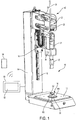
- the in the Fig. 1 and 2 illustrated ultrasonic processing machine 10 has a base plate 12, on which a workpiece to be welded is arranged, and which is rigidly connected to an upright stand 14.
- a guide rail 16 is fixed to the stator 14, along which a frame-like carriage 18 is slidably guided, which carries a vibration generator 21, with which a sonotrode 20 serving as a working organ can be excited to high-frequency oscillations.
- a linear drive 22 is provided in the described embodiment in the form of a spindle drive, the threaded spindle 24 is mounted upright on the frame-like slide 14, that the vibration generator 21 is in alignment with the travel of the linear drive 22, ie in the spindle axis.
- the linear drive 22 and in particular its spindle nut 28 is supported in the embodiment shown here in the manner according to the invention on a designated in its entirety by the reference numeral 40 frame-like elastically deformable solid-steel joint of steel, which in turn is freely cantilevered at the free end of the stator 14 ,
- a servomotor 26 is provided, the output gear via a belt drives the spindle nut 28, to which it is provided along its circumference with an external toothing.
- a controller 50 For controlling the processing machine for processing cycles and also for tensile test cycles, a controller 50 is provided which has an input device and an output device for input and output of operating parameters, for example in the form of a touch screen 52.
- the control stands both with the drive 22 as well the force measuring device and the displacement measuring device and with the vibration generator 21 in conjunction.
- any desired machining operation can be predetermined and carried out with the aid of the control.
- the controller causes the carriage 18 to be moved up with a predetermined force characteristic, the path traveled by the carriage being detected and recorded by the controller.
- the control can thus be used to log, store, display and output the tensile tests in data form.
- the controller 50 is furthermore wirelessly connected to a mobile operating device 54, for example a smartphone, with which the processing machine can be controlled via a corresponding app (application software).
- a mobile operating device 54 for example a smartphone, with which the processing machine can be controlled via a corresponding app (application software).
- Fig. 1 the workpiece W located on the base plate 12 is shown purely schematically and comprises a first component W1, which is welded to a second component W2 along two welding lines S1 and S2.
- the workpiece W can be fixed with its fixing elements, not shown, on the base plate 12 in its position, so that by lowering the carriage 18 by means of the sonotrode 20 welding along the weld lines S1 and S2 can be done.
- the spindle nut 28 is driven by means of the servo motor 26 and thereby the carriage 18 including the vibration generator 21 and sonotrode 20 is lowered until the sonotrode 20 comes into contact with the component W1 of the workpiece 12 located on the base plate, whereby by means of the linear drive 22 via the sonotrode 20 can be applied a welding force on the workpiece located on the base plate 12 in the desired manner, which, in particular when the workpiece is relatively rigid or unyielding, results in the frame-like solid-state hinge 40 undergoing elastic deformation in the desired manner ,
- the vibration generator 21 together with its sonotrode 20 is in alignment with the travel of the linear drive 22, there are no or only slight deformations in the force flow path between the sonotrode 20 and the stator 14, apart from this elastic deformation of the elastically deformable solid-body joint 40. Since the working member 20 is in alignment with the travel of the linear drive 22, it is ensured that it due to a force which is applied by means of the linear actuator 22 via the working member 20 to a positionable on the base plate 12 workpiece, no uncontrolled bending deformations in the region of the linear drive 22 and / or the vibration generator 21 comes.
- the linear actuator 22 within certain limits its stroke from the time when the working member 20 comes into abutment with the workpiece, so as to be from the time occurring from this stroke on the Adjust workpiece applied force without causing overshoots.
- a tensile test cycle should or must be performed, then the in Fig. 1 shown processing machine can be converted in the simplest way in a Switzerlandprüfvorraum.
- a first receiving device in the form of two holes 30 (in Fig. 1 If only one bore is visible), into which a first workpiece holder 32 can be inserted.
- Fig. 2 shows the inserted into the receiving device 30 workpiece holder 32, which in the illustrated embodiment, purely by way of example comprises only two schematically illustrated triangular bracket, wherein the in Fig. 2 upper bracket is inserted with two free legs in the receiving device 30 of the processing machine 10.
- the in Fig. 2 lower bracket is passed through a hole in the first component W1 of the workpiece and coupled to the upper bracket by means of two hooks, so that the first component W1 can be acted upon by means of the drive 22 in the direction of the arrow shown with force.
- the second component W2 of the workpiece W is fixed to the base plate 12 with the help of two purely schematically illustrated workpiece holders 34 and 36 so that the workpiece component W2 is held firmly on the base plate.
- the previously produced welded joint can be tested by recording the course of the applied tensile force over the path.
- the first workpiece holder 32 can be easily inserted into the receiving device 30 of the machine without the working member 20 would have to be removed in the form of sonotrode.
- the drive 22 When passing through a Switzerlandprüfzyklus the drive 22 is controlled by the controller 50 so that it moves the carriage 18 with a predetermined tensile force up, while using the Wegmeß worn and the force measuring device determines the course of the tensile force over the path and recorded becomes. If the result meets preset requirements, a signal is output and / or displayed or stored via the output device 52 or the operating device 54, which signals a positive fürlauft the train test. If the tensile test does not meet the requirements, this is also output or signaled.
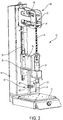
- Fig. 3 illustrated second embodiment of an ultrasonic machining machine is up to the workpiece holders for tensile test in the same way as the embodiment of Fig. 1 and 2 so that with respect to the basic construction on the description of the Fig. 1 and Fig. 2 can be referenced.
- the workpiece W and the first workpiece holder 32 and the second workpiece holder 34 are arranged in a free space at the bottom of the base plate 12, at the top of the carriage 18, at the back of the stator 14 and on the Front of the working member 20 is limited. Since no machine parts are arranged in this free space, this is suitable for attaching or housing the workpiece holders for tensile testing.
- the first workpiece holder 32 for tensile testing which in turn is shown only schematically, is used in this embodiment in a receiving device 30, which is located on the underside of the carriage 18.
- a second workpiece holder 34 which is substantially aligned with the first workpiece holder, is fastened to the base plate 12, but could also be fastened to the stator 14.
- a workpiece W previously welded together from two components W1 and W2 is arranged between the two workpiece holders 32 and 34, the first workpiece holder 32 holding component W1 and the second workpiece holder holding component W2.
- a force can then be exerted on the workpiece W in the direction of the arrow be exercised so that the strength of the weld between the components W1 and W2 can be tested for train.
- the two workpiece holders 32 and 34 can be threaded rods, which are screwed with their outer ends into the receiving device 30 and the base plate 12, wherein clamping devices for holding the two components are provided at the other ends of the two threaded rods could be.
- a controller 52 and an operating device 54 are provided or may be provided, as in connection with the embodiment of Fig. 1 and Fig. 2 has been described.
- controller 50 provided according to the invention is designed as described in the introduction to the description, so that it can be switched by the controller between processing cycles and Wegprüfzyklen according to desired criteria.
Landscapes
- Engineering & Computer Science (AREA)
- Mechanical Engineering (AREA)
- Physics & Mathematics (AREA)
- Optics & Photonics (AREA)
- Biochemistry (AREA)
- Life Sciences & Earth Sciences (AREA)
- Chemical & Material Sciences (AREA)
- Analytical Chemistry (AREA)
- Health & Medical Sciences (AREA)
- General Health & Medical Sciences (AREA)
- General Physics & Mathematics (AREA)
- Immunology (AREA)
- Pathology (AREA)
- Investigating Strength Of Materials By Application Of Mechanical Stress (AREA)
- Pressure Welding/Diffusion-Bonding (AREA)
- General Electrical Machinery Utilizing Piezoelectricity, Electrostriction Or Magnetostriction (AREA)
Priority Applications (2)
| Application Number | Priority Date | Filing Date | Title |
|---|---|---|---|
| PL17150862T PL3210709T3 (pl) | 2016-02-08 | 2017-01-10 | Obrabiarka ultradźwiękowa |
| SI201730004T SI3210709T1 (sl) | 2016-02-08 | 2017-01-10 | Ultrazvočni obdelovalni stroj |
Applications Claiming Priority (1)
| Application Number | Priority Date | Filing Date | Title |
|---|---|---|---|
| DE102016102164.4A DE102016102164A1 (de) | 2016-02-08 | 2016-02-08 | Ultraschall-Bearbeitungsmaschine |
Publications (3)
| Publication Number | Publication Date |
|---|---|
| EP3210709A2 true EP3210709A2 (fr) | 2017-08-30 |
| EP3210709A3 EP3210709A3 (fr) | 2017-12-27 |
| EP3210709B1 EP3210709B1 (fr) | 2018-08-01 |
Family
ID=57758546
Family Applications (1)
| Application Number | Title | Priority Date | Filing Date |
|---|---|---|---|
| EP17150862.5A Active EP3210709B1 (fr) | 2016-02-08 | 2017-01-10 | Machine d'usinage à ultrasons |
Country Status (8)
| Country | Link |
|---|---|
| US (1) | US9919471B2 (fr) |
| EP (1) | EP3210709B1 (fr) |
| DE (1) | DE102016102164A1 (fr) |
| ES (1) | ES2693426T3 (fr) |
| HU (1) | HUE041588T2 (fr) |
| PL (1) | PL3210709T3 (fr) |
| PT (1) | PT3210709T (fr) |
| SI (1) | SI3210709T1 (fr) |
Cited By (1)
| Publication number | Priority date | Publication date | Assignee | Title |
|---|---|---|---|---|
| CN108581172A (zh) * | 2018-05-10 | 2018-09-28 | 刘超 | 一种超声波焊接座结构 |
Families Citing this family (5)
| Publication number | Priority date | Publication date | Assignee | Title |
|---|---|---|---|---|
| DE102013015685A1 (de) | 2013-09-23 | 2015-03-26 | Man Diesel & Turbo Se | Werkzeugmaschine |
| US10241090B2 (en) * | 2016-04-29 | 2019-03-26 | GM Global Technology Operations LLC | Method and apparatus for evaluating an ultrasonic weld junction |
| JP7077650B2 (ja) * | 2018-02-16 | 2022-05-31 | トヨタ自動車株式会社 | ボンディング装置、及びボンディング方法 |
| DE102018119618A1 (de) * | 2018-08-13 | 2020-02-13 | Branson Ultraschall Niederlassung Der Emerson Technologies Gmbh & Co. Ohg | Schweißvorrichtung und Gestell dafür |
| DE102021126774A1 (de) | 2021-10-15 | 2023-04-20 | Ms Ultraschall Technologie Gmbh | Vorrichtung und verfahren zum bearbeiten eines werkstücks |
Family Cites Families (19)
| Publication number | Priority date | Publication date | Assignee | Title |
|---|---|---|---|---|
| US4373653A (en) | 1981-09-10 | 1983-02-15 | Raytheon Company | Method and apparatus for ultrasonic bonding |
| DE4024778A1 (de) * | 1990-08-04 | 1992-02-06 | Nagel Masch Werkzeug | Hon-messwerkzeug |
| JPH04250334A (ja) * | 1991-01-21 | 1992-09-07 | Sumitomo Metal Ind Ltd | ストリップ溶接部の検査方法および装置 |
| GB2260096B (en) | 1991-08-31 | 1995-05-17 | Hydro Marine Systems Limited | A method of and apparatus for testing the integrity of a friction weld |
| DE4312439C2 (de) * | 1993-04-16 | 1995-02-09 | Ilch Hartmut Dipl Ing Fh | Vorrichtung und Verfahren zum Verschweißen eines Anschweißteils und eines Basisteils |
| DE9313741U1 (de) | 1993-09-13 | 1995-01-19 | Still Gerhard | Vorrichtung zur Prüfung einer Schweißverbindung |
| US5788791A (en) | 1996-07-03 | 1998-08-04 | Branson Ultrasonics Corporation | Method of determining the collapse of plastic parts |
| US5894981A (en) | 1996-11-27 | 1999-04-20 | Orthodyne Electronics Corporation | Integrated pull tester with an ultrasonic wire bonder |
| JPH11281566A (ja) * | 1998-03-26 | 1999-10-15 | Mekano Electronic Kk | 半導体バンプ電極の試験方法 |
| US6237833B1 (en) | 1998-06-15 | 2001-05-29 | Rohm Co., Ltd. | Method of checking wirebond condition |
| JP2001118887A (ja) * | 1999-10-14 | 2001-04-27 | Resuka:Kk | ボンディング強度試験装置 |
| JP3907951B2 (ja) | 2001-01-18 | 2007-04-18 | 積水ハウス株式会社 | 溶接設備展示装置 |
| DE50110953D1 (de) * | 2001-11-07 | 2006-10-19 | F & K Delvotec Bondtech Gmbh | Prüfverfahren für Bondverbindungen und Drahtbonder |
| WO2007091931A1 (fr) * | 2006-02-10 | 2007-08-16 | Sca Hygiene Products Ab | Dispositif et moyen de traitement d'un materiau par ultrasons |
| US8052816B2 (en) * | 2006-05-08 | 2011-11-08 | Dukane Corporation | Ultrasonic press using servo motor with delayed motion |
| DE102006049624B4 (de) | 2006-10-20 | 2016-07-14 | Hesse Gmbh | Ultraschallbonder |
| DE102010006130B4 (de) * | 2010-01-29 | 2014-11-06 | F&K Delvotec Semiconductor Gmbh | Verfahren und Anordnung zur Qualitätsbestimmung einer Drahtbondverbindung |
| US8672211B2 (en) * | 2012-05-18 | 2014-03-18 | GM Global Technology Operations LLC | Vibration welding system with thin film sensor |
| DE102014101627A1 (de) * | 2014-02-10 | 2015-08-13 | Ms Spaichingen Gmbh | Gestell für eine Maschine |
-
2016
- 2016-02-08 DE DE102016102164.4A patent/DE102016102164A1/de not_active Withdrawn
-
2017
- 2017-01-10 ES ES17150862.5T patent/ES2693426T3/es active Active
- 2017-01-10 EP EP17150862.5A patent/EP3210709B1/fr active Active
- 2017-01-10 PL PL17150862T patent/PL3210709T3/pl unknown
- 2017-01-10 PT PT17150862T patent/PT3210709T/pt unknown
- 2017-01-10 HU HUE17150862A patent/HUE041588T2/hu unknown
- 2017-01-10 SI SI201730004T patent/SI3210709T1/sl unknown
- 2017-02-08 US US15/427,509 patent/US9919471B2/en active Active
Non-Patent Citations (1)
| Title |
|---|
| None |
Cited By (1)
| Publication number | Priority date | Publication date | Assignee | Title |
|---|---|---|---|---|
| CN108581172A (zh) * | 2018-05-10 | 2018-09-28 | 刘超 | 一种超声波焊接座结构 |
Also Published As
| Publication number | Publication date |
|---|---|
| US9919471B2 (en) | 2018-03-20 |
| EP3210709B1 (fr) | 2018-08-01 |
| SI3210709T1 (sl) | 2018-11-30 |
| PL3210709T3 (pl) | 2018-12-31 |
| DE102016102164A1 (de) | 2017-08-10 |
| HUE041588T2 (hu) | 2019-05-28 |
| EP3210709A3 (fr) | 2017-12-27 |
| PT3210709T (pt) | 2018-11-15 |
| US20170232660A1 (en) | 2017-08-17 |
| ES2693426T3 (es) | 2018-12-11 |
Similar Documents
| Publication | Publication Date | Title |
|---|---|---|
| EP3210709B1 (fr) | Machine d'usinage à ultrasons | |
| EP1798019A1 (fr) | Dispositif pour réaliser des travaux d'estampage, de fraisage, de soudage ou bien de collage sur des pièces en plastique tridimensionnelles de grandes dimensions | |
| DE202004010386U1 (de) | Pressschweißmaschine | |
| EP1677942B1 (fr) | Procede pour souder des conducteurs | |
| DE102015122314B3 (de) | Linearreibschweißmaschine | |
| DE102009004139B4 (de) | Vorrichtung zur Montage und Demontage eines Profilrohrs mit bzw. von einer Gelenkgabel einer Kreuzgelenkwelle | |
| EP2926943B1 (fr) | Dispositif d'usinage de profilés et procédé destiné à l'usinage de profilés | |
| EP2873512B1 (fr) | Dispositif de poinçonnage et de soudage de pièces en matière plastique | |
| EP2548668A1 (fr) | Procédé de dressage par torsion automatique de pièces allongées et dresseuse destinée à l'exécution du procédé | |
| DE102013214017B3 (de) | Positioniervorrichtung zum Positionieren von Werkstücken, Werkzeugmaschine mit einer derartigen Positioniervorrichtung, Verfahren zum Positionieren von Werkstücken | |
| EP3162496B1 (fr) | Dispositif d'assemblage de plusieurs éléments fonctionnels sur un arbre | |
| DE10138947A1 (de) | Kurzzeit-Lichtbogenschweisssystem und Verfahren zum Kurzzeit-Lichtbogenschweissen | |
| EP2995417B1 (fr) | Dispositif de montage d'au moins un element fonctionnel presentant un evidement pour un arbre | |
| AT523568A1 (de) | Biegemaschine | |
| DE202005007282U1 (de) | Vibrationsschweißanlage | |
| DE102015006421A1 (de) | Verfahren und Vorrichtung zum Fügen von Bauteilen | |
| DE202011050606U1 (de) | Abbrennstumpfschweißmaschine | |
| DE102008009881A1 (de) | Werkstückstütze und Verfahren zur Stabilisierung eines Werkstückes | |
| DE102008016818A1 (de) | Mobiler Reibschweißkopf und mobiles Reibschweißverfahren | |
| DE102016207697A1 (de) | Verfahren zum Verbinden wenigstens zweier Bauteile mittels einer Stanznietvorrichtung, Stanznietvorrichtung und Fertigungseinrichtung | |
| DE102015014625A1 (de) | Verfahren zum zerspanenden Bearbeiten wenigstens eines Strukturelements für einen Kraftwagen | |
| DE602004002223T2 (de) | Verfahren und Vorrichtung zur Lageerfassung eines mechanischen Teils in einer Aufnahme | |
| DE102022108397A1 (de) | Vorrichtung zum Ultraschallschweißen eines Werkstücks und Verfahren zum Betreiben einer solchen Vorrichtung | |
| DE102011015705A1 (de) | Radialpresse | |
| DE10106130C1 (de) | Verfahren zur Durchgangs- und/oder Reinheitsprüfung von Bohrungen und Vorrichtung zur Durchführung des Verfahrens |
Legal Events
| Date | Code | Title | Description |
|---|---|---|---|
| PUAI | Public reference made under article 153(3) epc to a published international application that has entered the european phase |
Free format text: ORIGINAL CODE: 0009012 |
|
| STAA | Information on the status of an ep patent application or granted ep patent |
Free format text: STATUS: THE APPLICATION HAS BEEN PUBLISHED |
|
| AK | Designated contracting states |
Kind code of ref document: A2 Designated state(s): AL AT BE BG CH CY CZ DE DK EE ES FI FR GB GR HR HU IE IS IT LI LT LU LV MC MK MT NL NO PL PT RO RS SE SI SK SM TR |
|
| AX | Request for extension of the european patent |
Extension state: BA ME |
|
| PUAL | Search report despatched |
Free format text: ORIGINAL CODE: 0009013 |
|
| AK | Designated contracting states |
Kind code of ref document: A3 Designated state(s): AL AT BE BG CH CY CZ DE DK EE ES FI FR GB GR HR HU IE IS IT LI LT LU LV MC MK MT NL NO PL PT RO RS SE SI SK SM TR |
|
| AX | Request for extension of the european patent |
Extension state: BA ME |
|
| RIC1 | Information provided on ipc code assigned before grant |
Ipc: B29C 65/00 20060101ALI20171120BHEP Ipc: B23K 37/02 20060101ALI20171120BHEP Ipc: G01N 3/16 20060101ALI20171120BHEP Ipc: B23K 20/10 20060101AFI20171120BHEP Ipc: B29C 65/74 20060101ALI20171120BHEP Ipc: B29C 65/08 20060101ALI20171120BHEP Ipc: B23K 103/00 20060101ALN20171120BHEP |
|
| STAA | Information on the status of an ep patent application or granted ep patent |
Free format text: STATUS: REQUEST FOR EXAMINATION WAS MADE |
|
| 17P | Request for examination filed |
Effective date: 20171215 |
|
| RBV | Designated contracting states (corrected) |
Designated state(s): AL AT BE BG CH CY CZ DE DK EE ES FI FR GB GR HR HU IE IS IT LI LT LU LV MC MK MT NL NO PL PT RO RS SE SI SK SM TR |
|
| GRAP | Despatch of communication of intention to grant a patent |
Free format text: ORIGINAL CODE: EPIDOSNIGR1 |
|
| STAA | Information on the status of an ep patent application or granted ep patent |
Free format text: STATUS: GRANT OF PATENT IS INTENDED |
|
| RIC1 | Information provided on ipc code assigned before grant |
Ipc: B29C 65/00 20060101ALI20180118BHEP Ipc: B29C 65/74 20060101ALI20180118BHEP Ipc: B23K 20/10 20060101AFI20180118BHEP Ipc: B29C 65/08 20060101ALI20180118BHEP Ipc: G01N 3/16 20060101ALI20180118BHEP Ipc: B23K 37/02 20060101ALI20180118BHEP Ipc: B23K 103/00 20060101ALN20180118BHEP |
|
| INTG | Intention to grant announced |
Effective date: 20180207 |
|
| RIC1 | Information provided on ipc code assigned before grant |
Ipc: B29C 65/00 20060101ALI20180126BHEP Ipc: B29C 65/74 20060101ALI20180126BHEP Ipc: G01N 3/16 20060101ALI20180126BHEP Ipc: B29C 65/08 20060101ALI20180126BHEP Ipc: B23K 37/02 20060101ALI20180126BHEP Ipc: B23K 103/00 20060101ALN20180126BHEP Ipc: B23K 20/10 20060101AFI20180126BHEP |
|
| GRAS | Grant fee paid |
Free format text: ORIGINAL CODE: EPIDOSNIGR3 |
|
| GRAA | (expected) grant |
Free format text: ORIGINAL CODE: 0009210 |
|
| STAA | Information on the status of an ep patent application or granted ep patent |
Free format text: STATUS: THE PATENT HAS BEEN GRANTED |
|
| AK | Designated contracting states |
Kind code of ref document: B1 Designated state(s): AL AT BE BG CH CY CZ DE DK EE ES FI FR GB GR HR HU IE IS IT LI LT LU LV MC MK MT NL NO PL PT RO RS SE SI SK SM TR |
|
| REG | Reference to a national code |
Ref country code: GB Ref legal event code: FG4D Free format text: NOT ENGLISH |
|
| REG | Reference to a national code |
Ref country code: CH Ref legal event code: EP Ref country code: CH Ref legal event code: NV Representative=s name: DR. GRAF AND PARTNER AG INTELLECTUAL PROPERTY, CH Ref country code: AT Ref legal event code: REF Ref document number: 1023726 Country of ref document: AT Kind code of ref document: T Effective date: 20180815 |
|
| REG | Reference to a national code |
Ref country code: IE Ref legal event code: FG4D Free format text: LANGUAGE OF EP DOCUMENT: GERMAN |
|
| REG | Reference to a national code |
Ref country code: DE Ref legal event code: R096 Ref document number: 502017000090 Country of ref document: DE |
|
| REG | Reference to a national code |
Ref country code: SE Ref legal event code: TRGR |
|
| REG | Reference to a national code |
Ref country code: PT Ref legal event code: SC4A Ref document number: 3210709 Country of ref document: PT Date of ref document: 20181115 Kind code of ref document: T Free format text: AVAILABILITY OF NATIONAL TRANSLATION Effective date: 20181026 |
|
| REG | Reference to a national code |
Ref country code: NL Ref legal event code: MP Effective date: 20180801 |
|
| REG | Reference to a national code |
Ref country code: ES Ref legal event code: FG2A Ref document number: 2693426 Country of ref document: ES Kind code of ref document: T3 Effective date: 20181211 |
|
| REG | Reference to a national code |
Ref country code: LT Ref legal event code: MG4D |
|
| PG25 | Lapsed in a contracting state [announced via postgrant information from national office to epo] |
Ref country code: FI Free format text: LAPSE BECAUSE OF FAILURE TO SUBMIT A TRANSLATION OF THE DESCRIPTION OR TO PAY THE FEE WITHIN THE PRESCRIBED TIME-LIMIT Effective date: 20180801 Ref country code: LT Free format text: LAPSE BECAUSE OF FAILURE TO SUBMIT A TRANSLATION OF THE DESCRIPTION OR TO PAY THE FEE WITHIN THE PRESCRIBED TIME-LIMIT Effective date: 20180801 Ref country code: IS Free format text: LAPSE BECAUSE OF FAILURE TO SUBMIT A TRANSLATION OF THE DESCRIPTION OR TO PAY THE FEE WITHIN THE PRESCRIBED TIME-LIMIT Effective date: 20181201 Ref country code: RS Free format text: LAPSE BECAUSE OF FAILURE TO SUBMIT A TRANSLATION OF THE DESCRIPTION OR TO PAY THE FEE WITHIN THE PRESCRIBED TIME-LIMIT Effective date: 20180801 Ref country code: GR Free format text: LAPSE BECAUSE OF FAILURE TO SUBMIT A TRANSLATION OF THE DESCRIPTION OR TO PAY THE FEE WITHIN THE PRESCRIBED TIME-LIMIT Effective date: 20181102 Ref country code: BG Free format text: LAPSE BECAUSE OF FAILURE TO SUBMIT A TRANSLATION OF THE DESCRIPTION OR TO PAY THE FEE WITHIN THE PRESCRIBED TIME-LIMIT Effective date: 20181101 Ref country code: NO Free format text: LAPSE BECAUSE OF FAILURE TO SUBMIT A TRANSLATION OF THE DESCRIPTION OR TO PAY THE FEE WITHIN THE PRESCRIBED TIME-LIMIT Effective date: 20181101 Ref country code: NL Free format text: LAPSE BECAUSE OF FAILURE TO SUBMIT A TRANSLATION OF THE DESCRIPTION OR TO PAY THE FEE WITHIN THE PRESCRIBED TIME-LIMIT Effective date: 20180801 |
|
| REG | Reference to a national code |
Ref country code: SK Ref legal event code: T3 Ref document number: E 28802 Country of ref document: SK |
|
| PG25 | Lapsed in a contracting state [announced via postgrant information from national office to epo] |
Ref country code: HR Free format text: LAPSE BECAUSE OF FAILURE TO SUBMIT A TRANSLATION OF THE DESCRIPTION OR TO PAY THE FEE WITHIN THE PRESCRIBED TIME-LIMIT Effective date: 20180801 Ref country code: LV Free format text: LAPSE BECAUSE OF FAILURE TO SUBMIT A TRANSLATION OF THE DESCRIPTION OR TO PAY THE FEE WITHIN THE PRESCRIBED TIME-LIMIT Effective date: 20180801 Ref country code: AL Free format text: LAPSE BECAUSE OF FAILURE TO SUBMIT A TRANSLATION OF THE DESCRIPTION OR TO PAY THE FEE WITHIN THE PRESCRIBED TIME-LIMIT Effective date: 20180801 |
|
| PG25 | Lapsed in a contracting state [announced via postgrant information from national office to epo] |
Ref country code: EE Free format text: LAPSE BECAUSE OF FAILURE TO SUBMIT A TRANSLATION OF THE DESCRIPTION OR TO PAY THE FEE WITHIN THE PRESCRIBED TIME-LIMIT Effective date: 20180801 |
|
| REG | Reference to a national code |
Ref country code: DE Ref legal event code: R097 Ref document number: 502017000090 Country of ref document: DE |
|
| REG | Reference to a national code |
Ref country code: HU Ref legal event code: AG4A Ref document number: E041588 Country of ref document: HU |
|
| PG25 | Lapsed in a contracting state [announced via postgrant information from national office to epo] |
Ref country code: DK Free format text: LAPSE BECAUSE OF FAILURE TO SUBMIT A TRANSLATION OF THE DESCRIPTION OR TO PAY THE FEE WITHIN THE PRESCRIBED TIME-LIMIT Effective date: 20180801 Ref country code: SM Free format text: LAPSE BECAUSE OF FAILURE TO SUBMIT A TRANSLATION OF THE DESCRIPTION OR TO PAY THE FEE WITHIN THE PRESCRIBED TIME-LIMIT Effective date: 20180801 |
|
| PLBE | No opposition filed within time limit |
Free format text: ORIGINAL CODE: 0009261 |
|
| STAA | Information on the status of an ep patent application or granted ep patent |
Free format text: STATUS: NO OPPOSITION FILED WITHIN TIME LIMIT |
|
| 26N | No opposition filed |
Effective date: 20190503 |
|
| PG25 | Lapsed in a contracting state [announced via postgrant information from national office to epo] |
Ref country code: MC Free format text: LAPSE BECAUSE OF FAILURE TO SUBMIT A TRANSLATION OF THE DESCRIPTION OR TO PAY THE FEE WITHIN THE PRESCRIBED TIME-LIMIT Effective date: 20180801 |
|
| PG25 | Lapsed in a contracting state [announced via postgrant information from national office to epo] |
Ref country code: LU Free format text: LAPSE BECAUSE OF NON-PAYMENT OF DUE FEES Effective date: 20190110 |
|
| REG | Reference to a national code |
Ref country code: IE Ref legal event code: MM4A |
|
| PG25 | Lapsed in a contracting state [announced via postgrant information from national office to epo] |
Ref country code: IE Free format text: LAPSE BECAUSE OF NON-PAYMENT OF DUE FEES Effective date: 20190110 |
|
| PG25 | Lapsed in a contracting state [announced via postgrant information from national office to epo] |
Ref country code: MT Free format text: LAPSE BECAUSE OF FAILURE TO SUBMIT A TRANSLATION OF THE DESCRIPTION OR TO PAY THE FEE WITHIN THE PRESCRIBED TIME-LIMIT Effective date: 20180801 |
|
| PG25 | Lapsed in a contracting state [announced via postgrant information from national office to epo] |
Ref country code: CY Free format text: LAPSE BECAUSE OF FAILURE TO SUBMIT A TRANSLATION OF THE DESCRIPTION OR TO PAY THE FEE WITHIN THE PRESCRIBED TIME-LIMIT Effective date: 20180801 |
|
| PG25 | Lapsed in a contracting state [announced via postgrant information from national office to epo] |
Ref country code: MK Free format text: LAPSE BECAUSE OF FAILURE TO SUBMIT A TRANSLATION OF THE DESCRIPTION OR TO PAY THE FEE WITHIN THE PRESCRIBED TIME-LIMIT Effective date: 20180801 |
|
| PGFP | Annual fee paid to national office [announced via postgrant information from national office to epo] |
Ref country code: PL Payment date: 20221227 Year of fee payment: 7 |
|
| PGFP | Annual fee paid to national office [announced via postgrant information from national office to epo] |
Ref country code: FR Payment date: 20230124 Year of fee payment: 7 |
|
| PGFP | Annual fee paid to national office [announced via postgrant information from national office to epo] |
Ref country code: TR Payment date: 20230109 Year of fee payment: 7 Ref country code: SE Payment date: 20230119 Year of fee payment: 7 Ref country code: IT Payment date: 20230120 Year of fee payment: 7 Ref country code: BE Payment date: 20230119 Year of fee payment: 7 |
|
| PGFP | Annual fee paid to national office [announced via postgrant information from national office to epo] |
Ref country code: RO Payment date: 20231228 Year of fee payment: 8 Ref country code: PT Payment date: 20231221 Year of fee payment: 8 |
|
| PGFP | Annual fee paid to national office [announced via postgrant information from national office to epo] |
Ref country code: ES Payment date: 20240227 Year of fee payment: 8 |
|
| PGFP | Annual fee paid to national office [announced via postgrant information from national office to epo] |
Ref country code: AT Payment date: 20240122 Year of fee payment: 8 |
|
| PGFP | Annual fee paid to national office [announced via postgrant information from national office to epo] |
Ref country code: HU Payment date: 20240123 Year of fee payment: 8 Ref country code: DE Payment date: 20240326 Year of fee payment: 8 Ref country code: CZ Payment date: 20231229 Year of fee payment: 8 Ref country code: GB Payment date: 20240119 Year of fee payment: 8 Ref country code: CH Payment date: 20240201 Year of fee payment: 8 Ref country code: SK Payment date: 20240104 Year of fee payment: 8 |
|
| PGFP | Annual fee paid to national office [announced via postgrant information from national office to epo] |
Ref country code: SI Payment date: 20231228 Year of fee payment: 8 |